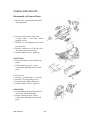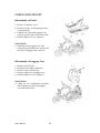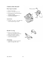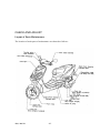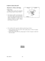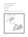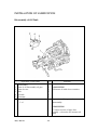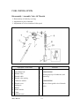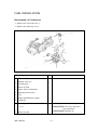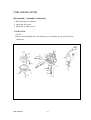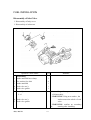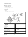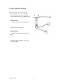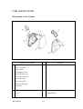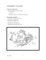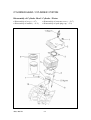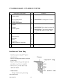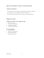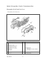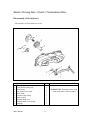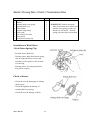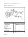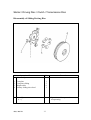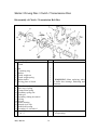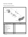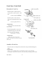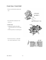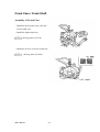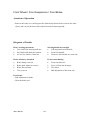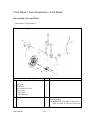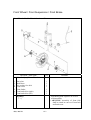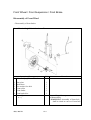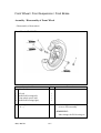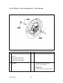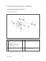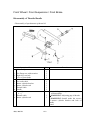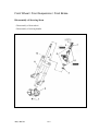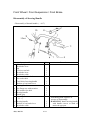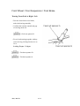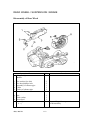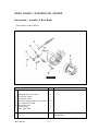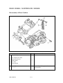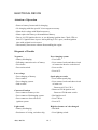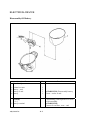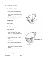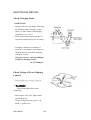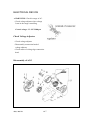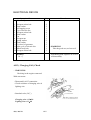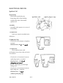
1
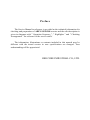
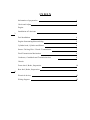
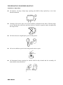
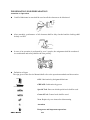
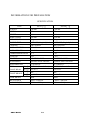
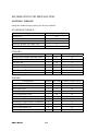
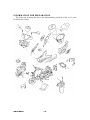
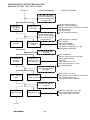
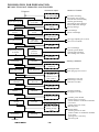
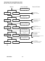
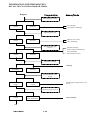
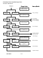
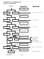
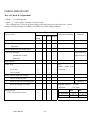
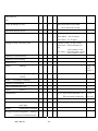
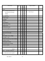
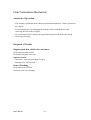
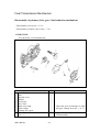
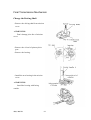
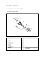
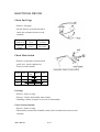
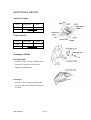
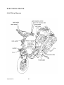
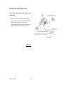
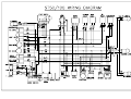
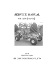
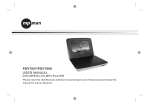
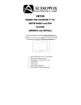
SERVICE MANUAL
SS-50/100
March, 2008
High Power Engine
HER CHEE INDUSTRIAL CO., LTD.
Preface
The Service Manual in reference is provided as the technical information for
checking and preparation of ADLY SS-50/100 scooter and the edit description is
given in diagrams with " Operation Sequence ", " Highlights " and " Checking
Arrangement " for reference of the service staffs.
The information, illustrations or contents included in this manual may be
different with the actual scooter in case specifications are changed. Your
understanding will be appreciated.
HER CHEE INDUSTRIAL CO., LTD.
INDEX
Information of preparation
1
Check and Adjust
2
EngineInstallation of Lubricant
3
Fuel Installation
4
Engine dismounting/disassembling
5
Cylinder head, Cylinder and Piston
6
Starter / Driving Disc / Clutch / Transmission
7
Final Transmission Mechanism
8
Crankcase, Crankshaft and Transmission box
9
ChassisFront wheel, Brake, Suspension
10
Rear heel, Brake, Suspension
11
Electrical devices
12
Wiring diagram
13
INFORMATION FOR PREPARATION
Attention on Operation
z
All washers, oil rings, clamp rings, opening pins shall be duly replaced by a new item
when dismounted.
z
Locking of all screws, nuts, cross screws shall be performed in the order of first the large
screws and then the small ones and from inside to outside in opposite angles by tightening
the torque locks.
z
All items must use original parts, pure oil and greases.
z
All service shall use special tools and general tools to repair.
z
All dismounted items requiring for checks shall be duly cleaned and for assembly, all
items shall be duly lubricated.
ADLY MOTO
1-1
INFORMATION FOR PREPARATION
Attention on Operation
z
Certified lubricants in cans shall be used on all the elements to be lubricated.
z
After assembly, performance of all elements shall be duly checked and the locking shall
be duly verified.
z
In case of an operation is performed by over 2 people, the assignment shall be conducted
in coordination and safety shall be the first priority.
z
Definition of signs:
The sign given in the Service Manual shall refer to the operation methods and observation.
OIL: Lubrication by designated lubricant.
GREASE: Lubrication by grease
Special Tool: Parts on which special tools shall be used
General Tool: General tools shall be used
New: Replace by new items after dismounting
Attention
Dangerous and important operations
ADLY MOTO
1-2
INFORMATION FOR PREPARATION
SPECIFICATION
SS-50Ⅰ/Ⅱ
TYPE
SS-100Ⅰ/Ⅱ
LENGTH
1780 mm
1780 mm
WIDTH
675 mm
675 mm
HEIGHT
1160 mm
1160 mm
WHEEL BASE
1250 mm
1250 mm
NET WEIGHT
75 kg
75 kg
ENGINE TYPE
4-STROKE, Single Cylinder
4-STROKE, Single Cylinder
COOLING
AIR COOLED
AIR COOLED
DISPLACEMENT
49.26 C.C.
95.57 C.C.
BORE×STROKE
40.0×39.2
52×45
COMPRESSION RATIO 7.2:1
5.8:1
IGNITION
C.D.I
C.D.I
STARTER
ELECTRIC / KICK
ELECTRIC / KICK
SUSPENSION
Hydraulic Shock Absorber
Hydraulic Shock Absorber
TRANSMISSION
AUTOMATIC
AUTOMATIC
TIRE
FRONT/REAR
SS (Ⅰ) 120/70-12 (Front & Rear)
SS (Ⅱ) 120/70-12
FRONT BRAKE
SS (Ⅰ) Disc
SS (Ⅱ) Double Disc
120/70-12 (Front & Rear)
120/70-12
Disc
Double Disc
REAR BRAKE
Drum
Drum
MAX. POWER
2.8Kw / 5500 rpm
5.26kw / 7000 rpm
MAX. TORQUE
4.75N-m / 5500 rpm
7.4N-m / 6500rpm
ADLY MOTO
1-3
INFORMATION FOR PREPARATION
LOCKING TORQUE
Adopt the standard torque locking for the item unlisted.
STANDARD TORQUE:
Type
5 mm Screw
6 mm Screw
6 mm Hex Washer Face Bolt / Nut
8 mm Hex Washer Face Bolt / Nut
10 mm Hex Washer Face Bolt / Nut
Locking Torque (kg-m)
0.4
1.0
1.2
2.7
4.0
CHASSIS:
Locking Place
Spanner Nut of Handle Steering Steam
Front Wheel Axle Nut
Rear Axle Nut
Rear Brake Arm Screw
Upper Screw of Rear Shock Absorber
Lower Screw of Rear Shock Absorber
Engine Mounting Bracket
Quantity Dia. (mm) Locking Torque (kg-m)
1
25
7.0
1
10
4.5
1
14
11
1
5
0.6
1
10
4.0
1
8
2.7
1
8
6.0
ENGINE:
Locking Place
Quantity Dia. (mm) Locking Torque (kg-m)
Screw of Cylinder Cap
4
6
1.0
Flywheel Nut
1
10
3.8
Clutch Jacket Nut
1
11
3.8
Driving Disc Nut
1
28
5.5
Nut of Transmission Disc
1
10
3.8
Oil-check Screw
1
8
1.3
Joint Screw of Exhaust Manifold
2
6
1.2
Exhaust Pipe Support Screw of Muffler
2
6
1.2
Spark Plug
1
14
1.4
Bolt of Crank Shaft Case
6
6
10
Bolt of Engine Installation
1
8
5.0
ADLY MOTO
1-4
INFORMATION FOR PREPARATION
The following drawing that shows the disassembling situation of the cover parts
for SS50/100 scuuter.
ADLY MOTO
1-5
INFORMATION FOR PERPARATION
DIFFICULT START OR CANN'T START
Check and Adjuster
Diagnose
Reason of Trouble
loose the fuel release
screw of caruretor and
check if the fuel is inside
of carburetor ?
fuel supply to
carburetor is
sufficient
no fuel supply to
carburetor
loosen the spark plug,
connect with the spark
cap and contact with the
frame, check the spark
plug sparking ?
sparking
no sparking or
weak
fuel tank without gasoline
tubing to carburetor blocking
float chamber tubing of carburetor blocking
fuel filter blocking
fuel cup blocking
air hole of fuel tank blocking
spark plug grimy or damage
C.D.I damage
main switch damage
ACG fulser coil damage
high tension coil damage or no gap
ACG lighting coil damage
test the compression
pressure
compression
pressure
is normal
compression
pressure too low
or no pressure
follow the standard
stat-up procedure and
test again
engine can not
ignite
valve set damage
cylinder, piston, piston ring damage
cylinder gasket leakage
valve burn
valve timing is not correct
valve gap is too tight or no gap
start clutch damage
ignite timing is not correct
fuel adjuste screw of carburetor isn't correct
intake manifold sucking air
auto. plunger starter is damage
engine can ignite
but can not start
loosen the spark plug
and test
spark plug is dry
fuel level of carburetor is too high
auto. plunger starter is damage
throttle open angle is too wide
spark plug is wet
continue
ADLY MOTO
1-7
INFORMATION FOR PREPARATION
REVOLUTION NOT SMOOTH , LOST POWER
Diagnose
Check and Adjust
start engine and
go up speed slight
engine speed go up
engine speed can't
go up fully
adjusting ignite
timing
ignite timing is
correct
Reason of Trouble
air cleaner blocking
fuel supply isn't smooth
air hole of air tank blocking
exhaust pipe blocking
auto.plunger starter damage
film of carburetor damage
fuel cup damage
C.D.I damage
pulser coil damage
ignite timing isn't
correct
adjusting valve gap
is not correct
valve gap is correct
valve gap adjusting isn't correct
valve set over abrade
valve gap
isn't correct
testing compression
pressure
compression pressure
is normal
valve set damage
cylinder, piston abrade
cylinder gasket leakage
valve timing isn't correct
compression
pressure
is too low
check carburetor
blocking ?
no blocking
cleaning carburetor
blocking
loosen spark plug
and check
spark plug normal
cleaning the stain
spark plug type isn't correct
spark plug stain
check the oil
quantiity of
crankcase is too
rich or dirty?
oil quantity
is normal
oil quantity is
too rich
oil flowing is too rich
oil flowing is too lean
oil doesn't circulate
check cylinder head
lubricating ?
normal
oil tubing blocking
oil supply is too lean
abnormal
engine over heat
normal
over heat
increase engine
speed or continue
turning at high
speed
no knocking
knocking
continue
ADLY MOTO
1-8
cylinder, piston abrade
mixutre gases is too lean
carbon residue in combustion chamber
is too more
igniting time is too earily
fuel isn't good
clutch sliding
mixutre gases is too lean
carbon residue in combustion chamber
is too more
igniting time is too earily
fuel isn't good
INFORMATION FOR PREPARATION
REVOLUTION NOT STABLE (LOW R.P.M.)
Diagnose
Check and Adjust
Reason of Trouble
ignition timing adjusting
normal
C.D.I damage
pulser coil damage
abnormal
adjust the carburetor fuel
adjuste screw
adjusting is correct
mixture gases too lean
(loosing screw)
mixture gases too rich
(locking screw)
adjusting isn't
correct
carburetor sucking air
no sucking air
sucking air
loosen spark plug,
connecct with spark cap
and contract with frame,
check the spark plug
sparking ?
sparking normal
sparking abnormal
gasket damage
the screw of carburetor is
loosen
(-) pressure tube broken
spark damage or stain
C.D.I damage
A.C.G damage
coil damage
spark plug cable damage odr short
main switch damage
check A.C.G
normal
A.C.G damage
air hole damage or blocking
(-) pressure tube damage
abnormal
end
ADLY MOTO
1-9
INFORMATION FOR PREPARATION
REVOLUTION NOT SMOOTH(HIGH SPEED)
Check and Adjust
Diagnose
Reason of Trouble
adjusting ignite timeing
normal
C.D.I damage
ACG pulse coil damage
abnormal
adjusting valve gap
normal
adjusting isn't correct
valve set damage
abnormal
check fuel cup supply
normal ?
normal
fule filter blocking
air hole of fuel tank blocking
fuel cup damage
fuel of tank is too less
abnormal
carburetor blocking
cleaning
no blocking
blocking
check and adjust valve
timing
valve timing is
correct
camshaft gear mark position is not
correct
valve timing isn't
correct
check the spring of valve
normal
spring broken or
elastic deformation
spring damage
end
ADLY MOTO
1-10
INFORMATION FOR PREPARATION
CHARGE ABNORMAL
Check and Adjust
Diagnose
Reason of Trouble
start engine and measure
voltage of the two
terminal for battery
voltage of battery
can't go up
voltage of battery
is normal
battery damage
measure the resistance of
ACG coil
coil damage
terminal damage
YL wire damage
measure value
too high
normal
check the regulator
battery have voltage
battery have not
voltage
R wire damage
check socket of regulator
loosen ?
normal
regulator damage
socket damage
abnormal
ACG damage
(over charge)
check the voltage between
regulator and frame
main switch at ON
the battery have
voltage
main switch at ON
the battery have no
voltage
GR wire broken
check the socket of
regulator
normal
socket damage
socket loosen
regulator damage
ADLY MOTO
1-11
INFORMATION FOR PREPARATION
SPARK PLUG NO SPARKING
Check and Adjust
Diagnose
Reason of Trouble
change spark plug and
check again
no sparking or
weak
the previous spark plug damage
sparking strong
check spark plug, cap,
ignition coil loosen?
loosen
no loosen
spark plug cap loosen
check C.D.I unit socket
loosen ?
normal
abnormal
socket damage
check the terminal of
C.D.I unit unimpeded?
measure resistance
abnormal
normal
check relate spare parts
normal
main switch damage
pulser coil damage
coil damage
lighten coil damage
abnormal
main switch damage
socket, joint connect abnormal
change CDI unit
normal
the previous C.D.I unit damage
abnormal
change ignition coil
abnormal
ADLY MOTO
the previous coil damage
1-12
CHECK AND ADJUST
Way of Check & Adjustment
1. Mark “○” is checking time.
2. Mark “☆” is the regular exchange of service items.
This exchange time is just for general riding of the majority not for the special use , please
arrange with this principle according to the difference of the riding condition.
Service Items
Service Time (month)
Before
riding
Judgement Standard
Remarks
1 st each 6 each 12
Operating Device
○
Handle- Play, loose/tight
○
Operation
○
Wheels- Right/left turn round angle
Front Fork-Damage
Installation of shaft
○
○
Direction Post
○
○
Direction Post
○
Shaft Gap
Brake Device
○
○
Play
○
○
Handle , handle front
10-20 mm
○
○
○
○
○
○
○
○
Brake- Play
Try to run
○
Correct brake
○
Wires- Loose / tight and damage
Gap of casing & brake
○
Wore of brake & operating parts
Wore & Damage of casing
○
Riding Device
Tires-Air pressure of tires
ADLY MOTO
Direction
Standard diameter
110 mm
Limitation
110.5mm
front
○
○
2-1
○
rear
air pressure 1.5 kg/cm 1.75 kg/cm
tire
120/70-12 120/70-12
Riding Device
Tire
Check & damage of tires
○
○
○ Ditch-front wheel till 0.8mm
Rear wheel till 0.8 mm
Abnormal & ditch in tires
○
○
○
Bolt & nut of tires locking
Flocking torsion
○
○ Front wheel – 4.0~5.0 kg-m
Rear wheel –10~12 kg-m
Damage of felly ,side ring , disc
○
○
○ Vibration of felly, in edge of felly
Front wheel – horizontal under 2.0
mm
vertical under 2.0 mm
Rear wheel – horizontal under 2.0 mm
vertical under 2.0 mm
Tightness of front bearing
○
Tightness of rear bearing
○
Buffer device
Spring
○
-damage
Spring of
shock
absorber
○
Suspension arm – damage of joint gap
& arm
Buffer
○
-oil leakage or damage
○
Tightness of installation
Power transmission device
Clutch
-action
Transmission
○
○
○
○
○ Level : way of direction hole , oil
fill to the mark of the hole
Electril device
Ignition device
-condition of ignition
○
○
spark plug
Battery
○
-connection of terminal
○
Wiring of electrical appliance – damage
or loose in connection place
ADLY MOTO
2-2
Gap of spark plug 0.6~0.7 mm
It’s rear
Gear case
Check Items
Before 1 st
riding M
6
12
Judged standard
M
M
○
○
○
○ Idle : 1800±100 rpm
exhaust
○
○
air filter
○
○
Oil and oil filter
○
○ Warning light lighting
Oil leakage
○
○
Engine
Body – starting & abnormal noise
○
low speed & accelerating
Lubrication device
○
Oil level
Fuel installation
○
Gasoline filter is dirty
○
Leakage of fuel
○
Throttle gate & choke
○
Fuel filter is clogged
○
○
Oil level
Alteration of pipes
9 each 2 years
Lights & direction lights
○
Action
On/off normal , dirty , damage
○
Rear mirror – view
○
○
○
Reflector & license tag –dirty & damage
○
Instrument –action
Exhaust pipe & muffler
Installation loosed or damage
○
Function of muffler
○
Frame & body –loose or damage
○
Abnormal from previous day –confirm
normal
Others
- greasing of each part
○
○
○
Cleaning combustion chamber , exhaust
pipe , and carbon muck in muffler
ADLY MOTO
○
2-3
remarks
CHECK AND ADJUST
Disassembly of External Parts
• Remove the external parts for check
and adjustment.
• Remove 4 hex washer face bolts,
4 space tubes , and then remove
luggage carrier.
• Remove 12 self-tapping screws and 2
pan flat bolts.
• Remove central cover ,L/R side cover,
decoration strip and cowling.
• Install with the reverse sequence.
WARNNING:
6 Do not break the union of body and
pedal.
6 Before locking screws , please
confirm the matching correct of all
parts.
•
•
•
•
•
Front cover.
Remove 3 pan flat bolts , 1 hex bolt.
Remove 12 self-tapping screws.
Disconnect the light connectors.
Install with the reverse sequence.
WARNNING:
6 Do not damage & break the joint of
inner body and front damper.
6 Before locking screws , please
confirm the matching correct of all
parts.
ADLY MOTO
2-4
CHECK AND ADJUST
Disassembly of Pedal
• Remove L/R body cover.
• Remove 4 bolts, 6 self-tapping screws
2 pan flat bolts.
• Separate the joint with luggage case
(claw & groove)and remove the pedal
• Install with the reverse sequence.
WARNNING:
6 Installing to the luggage box after
composing confirming the pedal with
the joint of luggage case correctly.
Disassembly of Luggage Case
• Remove front fender.
• Disconnect the light connectors.
• Remove power switch cap.
• Remove edge nut on luggage case.
• Install with the reverse sequence.
WARNNING:
6 Going on the installation operation
after jointing correctly the luggage
case and front fender.
ADLY MOTO
2-5
CHECK AND ADJUST
Rear Light Assembly
• Remove 2 hex bolts.
• Remove 3 L/R sides body cover.
• Disassembly the connection head of
wireness rear light.
• Assembly with the sequence in
reverse of disassembly.
WARNNING:
6 Ensuring the joint of tail light hole
correct with the bulge of truck.
Handle Covering
• Remove 4 self-tapping screws ,
separate the joint with speedometer.
• Remove the handle covering.
• Assembly with the sequence in
reverse of disassembly.
WARNNING:
6 Aim handle covering correctly the
handle covering back’s joint.
ADLY MOTO
2-6
CHECK AND ADJUST
Layout of Parts Maintenance
The location of main parts of maintenance are showed as follows :
ADLY MOTO
2-7
CHECK AND ADJUST
Adjustment of Motor Oil Pump
4WARNNING:
Going on this operation after adjusting
and checking the guide wiring of throttle.
• The tolerance within 1 mm of the adjust
O/P control cable is good. Starting the
engine, turn slightly the throttle to feed
motor oil idle-speed. At same time of
rising the rotation of engine, confirm
the working of control rod.
• The condition will be appeared with bad synchronizing as follows :
6 Starting difficult and having smoke when opening degree of motor oil pump’s
connection rod is too big.
6 Piston will be burnt when the opening degree of motor oil pump’s connection
rod is too small.
MENO
ADLY MOTO
2-9
INSTALLATION OF LUBRICATION
Attention of Operation
‧Pay attention to avoid dust enter to the interior of engine and motor oil pipe when
disassembly the motor oil pump.
‧Never disassembly motor oil pump.
‧Must draw out the air on the pump if there have air in the pump when disassembly
pipe of carburetor.
‧After disassembling the motor oil connection tube, must fulfill the motor oil in the
connection pipe, then, connect the tube.
Diagnosis of Troubles
Too much smoke, means too much carbon muck piping up the spark plug.
‧Poor synchronizing adjust of motor oil pump (too much exhaust).
‧Bad quality of engine motor oil.
Overheating
‧Poor synchronizing adjustment of motor oil pump (too much exhaust).
‧Bad quality of engine motor oil.
Piston burnt
‧Short of engine oil, or engine oil pipe is clogged.
‧Poor adjustment of motor oil pump (lesser the exhaust).
‧There have air in the motor oil pipes system.
‧Bad motor oil pump.
Clogging oil from oil tank
‧Vent of motor oil case’s cap is clogged.
‧Filter of motor oil is clogged.
Preparation standard
‧Use separating motor oil appointed (use for 2-stroke).
‧Content of motor oil tank : 1.1 liter
ADLY MOTO
3-4
INSTALLATION OF LUBRICATION
Disassembly of Motor Oil Pump
• Remove right side cover.
• Remove stator cover.
• Remove A.C.G
4WARNNING:
Operating after cleaning motor oil pump around and no entering to the crank shaft
case.
ADLY MOTO
3-4
INSTALLATION OF LUBRICATION
Operation / Parts Name
Disassembly
1 Fuel pipe
2 Fuel connection pipe
3 Pan phillips bolt
4 Control cable
5 Motor oil pump
Assembly
5→1
Q’ty
Remarks
1 4WARNNING:
Clogging the pipe with clamp or plug
for avoiding fuel flow out.
1 • Remove from both side of motor oil
2 pump.
1/1 • Remove from oil pump.
1
• Assembly with sequence in reverse
of disassembly.
4WARNNING:
−Smear motor oil to new O ring ,then,
assembly motor oil pump.
−The oil pump must installed correctly
into crank case.
4WARNNING:
−Don’t loosen adjusted screw on control
cable, but must adjust oil pump after
assembling if need to loosen.
ADLY MOTO
3-4
INSTALLATION OF LUBRICATION
Disassembly of Oil Tank
Operation / Parts Name
1
2
3
4
5
Disassembly
Joint of oil disassembly oil pipe
Joint of wires
Bolt
Oil tank
Grommet
Assembly
5→1
Q’ty
Remarks
1 *WARNNING:
1 Fill motor oil with clean container.
1
1
1
• Operation with sequence in reverse of
disassembly.
*WARNNING:
Connect correct oil pipe after
assembly , release the air in motor oil
pump.
ADLY MOTO
3-4
FUEL INSTALLATION
Attention in Operation
h Pay attention to the parts which using gasoline.
h Pipes & Cable must be in accordance with the location directed of wiring diagram.
h Release air in motor oil pump when remove motor oil pipe.
Diagnosis of Trouble
No starting
h No gasoline in tank
h Gasoline blocked
h Too much fuel in cylinder
h Air filter is clogged
Idle speed unstable , of carburetor rotation not smooth
h Poor idle speed adjustment of carburetor.
h Low compression pressure
h Poor ignition system
h Bad adjustment of air adjusting screw on carburetor
h Air filter is clogged
h Poor auto side-plunger on carburetor
h Idle speed nozzle is clogged
Mixed air too thin
h Nozzle of carburetor is clogged
h Gasoline filter is clogged
h Vent of gasoline tank is clogged
h Gasoline pipe cranked, broke, clogged
h Poor action of valve of float chamber
h Gasoline level too low
h Air pipe is clogged
Mixed air too thick
h Poor action of valve of float chamber
h Gasoline level too high
h Air nozzle is clogged
h Auto side-plunger poor
ADLY MOTO
4-1
FUEL INSTALLATION
Disassembly / Assembly Valve Of Throttle
h Disassembly of left body covering
h Adjustment of play of throttle
h Adjustment of reverse rotation of idle speed
Operation / Parts Name
1
2
3
4
5
6
7
8
9
10
11
Disassembly
Pan phillips bolt
Throttle valve
Throttle cable
Throttle valve spring
Carburetor washer
Throttle cover
Sealing set
Washer
Needle nozzle
Clamp
Adjusted screw
ADLY MOTO
Q’ty
Remarks
2 *WARNNING:
1 Loosing top cap of carburetor, and
1 removing.
1
1 *WARNNING:
1 Remove from guide wire of throttle
1 valve.
1
1
1
1
4-2
FUEL INSTALLATION
Operation / Parts Name
11
10
9
8
7
6
5
4
3
2
Assembly
Adjusted screw
Clamp
Needle nozzle
Washer
Sealing set of guide wire
Throttle cover
Washer
Throttle valve spring
Throttle cable
Throttle valve
1 Pan Phillips bolt
ADLY MOTO
Q’ty
1
1
1
1
1
1
1
1
1
1
Remarks
*WARNNING: Assembly of needle nozzle.
*WARNNING: Assembly of throttle valve.
*WARNNING: Assembly of throttle cable.
*WARNNING: Aim the ditch of throttle
valve to chamber then install throttle
valve into carburetor.
Lock the throttle cover.
1
4-3
FUEL INSTALLATION
Disassembly of Carburetor
h Remove the air cleaner ass’y .
h Remove the left body cover
Operation / Parts Name
1
2
3
4
5
6
7
8
Disassembly
Throttle valve set
Gasoline pipe
Motor oil joint
Starter wire of carburetor
Vacuum pressure tube
Clip
Intake manifold hose clamp
Carburetor
Q’ty
Remarks
1
1
1
1
1
1
1
1
Assembly
8→1
3 Motor oil joint
ADLY MOTO
*WARNNING: Don’t let dust enter
into carburetor.
*WARNNING: Release air.
4-4
FUEL INSTALLATION
Disassembly / Assembly Carburetor
h Disassembling of carburetor.
h Adjust the idle speed.
h Adjust the air adjust screw.
*WARNNING:
․No fire.
․Before disassembling, loose oil-draining screw, draining out the gasoline from
carburetor.
ADLY MOTO
4-5
FUEL INSTALLATION
Operation / Parts Name
Q’ty
Remarks
Disassembly
Plunger starter
1 Pan Phillips bolt
2 Start plug screw
3 Oil ring
2
1
1
Float Chamber
4
5
6
7
8
9
10
Pan Phillips bolt
Drain plug
Over flow tube
Pan Phillips bolt
Float pin
Float
Needle valve
4
1
1
1
1
1
1
Carburetor Ass’y
11 Throttle screw set
12 Air adjust screw set
13 Float chamber seal
Assembly
13→1
12 Air adjust screw set
1
1 *WARNNING: Must confirm rerotation
location before disassembling ,
not locking too much avoid to
hurt seat face.
‧Operating with sequence in reverse of
Disassembling.
* WARNNING: use high pressure
air clean each way of carburetor.
*WARNNING: must adjust air screw
when changing air screw and
carburetor ass’y.
ADLY MOTO
4-6
FUEL INSTALLATION
Disassembly of Inlet Valve
h Disassembly of body cover.
h Disassembly of carburetor.
Operation / Parts Name
1
2
3
4
5
Disassembly
Intake manifold hose clamp
Hex washer face bolt
Intake manifold
Reed valve ass’y
Reed valve gasket
Q’ty
Remarks
1
4
1
1
1
‧Assembling with sequence in reverse
of disassembly.
Assembly
5→1
4WARNNING: Using new washer , the
washer must aim at hole of reed
valve.
4 Reed valve ass’y
5 Reed valve gasket
4WARNNING: confirm no secondary
air
entering after installing.
ADLY MOTO
4-7
FUEL INSTALLATION
Disassembly of Fuel Tank
‧Disassembly of body cover.
‧Disassembly of tail light fix bracket.
‧Disassembly of inner carrier.
*WARNNING:
․No fire.
․Shall be wiped off when fuel overflowed.
Operation / Parts Name
Disassembly
1
2
3
4
5
6
7
8
9
8
Hex bolt
Tail light fix bracket
Inner carrier
Oil tube
Tube
Petrol gauge ass’y
Joint of petrol gauge wire
Round phillips bolt
Oil lever gauge gasket
Hex flat head phillips bolt
Assembly
9→1
Oil lever gauge gasket
ADLY MOTO
Q’ty
Remarks
4
1
1
1
1
1 *WARNNING: Clip the tube, avoid fuel
4
over-flow.
1
4
‧Operating with sequence in reverse of
disassembly.
1 ‧Change new one.
4-8
FUEL INSTALLATION
Disassembly of Petrol Gauge
‧Disassembling wire joint of petrol
gauge and remove 4 hex phillips bolt.
*WARNNING:
Don’t damage petrol gauge wires.
‧Remove the petrol gauge.
*WARNNING:
Don’t curving float arm of petrol
gauge.
‧Operation with sequence in reverse
of disassembly.
ADLY MOTO
4-9
FUEL INSTALLATION
Disassembly of Air Cleaner
Operation / Parts Name
1
2
3
4
5
6
7
8
9
Disassembly
Hex socket bolt
Plain washer
Self-tapping screw
Air cleaner case cap
Air cleaner element
Air cleaner case
Air cleaner joint
Cleaner guide pipe
Grommet
Q’ty
2
1
3
1
4
1
1
2
1
‧Operating with sequence in reverse of
disassembly.
Assembly
9→1
ADLY MOTO
Remarks
4-10
DISASSEMBLY OF ENGINE
Attention of Operation
‧Operation after disassembling the engine.
–Crank shaft case
–Crank shaft
–Exchange bearing of final transmission mechanisms.
Disassembly of Engine
‧Disassembly of external cap of body.
‧Disassembly of luggage case.
‧Disassembly of throttle valve.
‧Adjustment the throttle cable.
‧Adjustment the rear break cable.
‧Adjustment the oil pump control cable.
ADLY MOTO
5-1
DISASSEMBLY OF ENGINE
Operation / Parts Name
1
2
3
4
5
6
7
8
9
10
11
12
13
14
15
16
Q’ty
Disassembly
ACG wire /wire of start motor
Starter wire of carburetor
Oil tube
Fuel tube
Vacuum pressure tube
Cap of spark plug
Hex washer face bolt of rear cushion
Oil pump control cable
Cable of rear brake
Throttle cable
Hex washer face bolt of engine
Bolt
Engine
Nut
Engine bracket bolt
Engine bracket
Remarks
2 *WARNNING:
1
The oil over-flow when remove the
1 oil tube , so use clip or plug stop the seal.
1
1
1
1
1
1
1
1
1
1 *WARNNING:
1 • Don’t damage rear fender when remove
2
the engine.
1 • Actually for brace the frame, avoid body
turn inside out.
*WARNNING: Carry out following adjusting
Assembly
16→1
after installation.
–Cable of throttle valve
–Oil pump control cable
–Rear break cable
ADLY MOTO
5-2
CYLINDER HEAD / CYLINDER / PISTON
Attention of Operation
• Can be operated when engine installed on vehicle.
• Must cleaning before operating , avoiding dust enter the engine.
• Remove the gasket dust stay on joint face.
• Avoid to use driver harm the joint face when remove the cylinder & cylinder head.
• Avoid to harm the cylinder inner and piston face.
• Cleaning before check parts, and smear motor oil appointed in sliding face before
installing.
Diagnosis of Troubles
Low compression pressure , poor start , idle speed not stable
• Air leakage of cylinder head washer.
• Wear & damage the piston ring.
• Wrong installation of spark plug
• Wear & damage the cylinder and piston.
• Inlet valve poor.
Compression pressure too high, overheating, locking
• Piling up carbon of cylinder head or piston head.
Piston Noise
• Wear the cylinder and piston.
• Wear the piston pin hole and piston pin.
• Wear the needle bearing of crank connecting rod (small end) .
Piston ring noise
• Wear or damage the piston ring.
• Wear or damage the cylinder.
ADLY MOTO
6-1
CYLINDER HEAD / CYLINDER / PISTON
Disassembly of Cylinder Head / Cylinder / Piston
• Disassembly of cover (→4-7)
• Disassembly of muffler (→11-2)
ADLY MOTO
• Disassembly of cenerator cover (→12-7)
• Disassembly of spark plug cap (→5-2)
6-2
CYLINDER HEAD / CYLINDER / PISTON
Operation / Parts Name
Q’ty
Remarks
Disassembly
Cylinder head
1 Nut of cylinder head
2 Cylinder head
3 Cylinder head gasket
Cylinder
4 4WARNNING: Loosing nut 2-3 times.
1
1
4 Cylinder
5 Cylinder gasket
1 4WARNNING: Don’t knock cooling fin.
1 4WARNNING: Clean and not damage
cylinder & washer of crank shaft
case.
Piston
6
7
8
9
10
Piston ring clip
Piston pin
Piston
Piston ring
needle bearing of small side
Assembly
10→1
2
1
1
2
1
‧Operation with sequence in reverse of
disassembly.
Installation of Piston Ring
‧Install top-piston ring & 2nd piston
ring in piston.
‧Do not scratch piston and do not bend
piston rings.
‧Remove carbon muck inside ring ditch
and piston ring when not installed.
‧Be sure the rings rotate freely after
install into piston.
4WARNNING:
Change whole set of piston ring
with same brand.
ADLY MOTO
6-3
Starter / Driving Disc / Clutch / Transmission Disc
Attention of Operation
‧Don’t make greases stick to surface of transmission belt or belt plate. Otherwise ,
the efficiency of power transmission will be lowered by skid.
‧Don’t rotation the starter when remove the front cap of left crankshaft case.
Diagnosis of Trouble
Vehicle does not move after engine start up
•
•
•
•
Drive belt wear-out
Drive face comp. damage
Clutch lining wear-out
Driven ass’y spring defect
Power insufficient
•
•
•
•
Drive belt wear-out
Driven ass’y spring defect
Drive face dirty or oily
Weight roller wear-out
ADLY MOTO
7-1
Starter / Driving Disc / Clutch / Transmission Disc
Disassembly of Left Crank Case Cover
‧Disassembly of air cleaner ass’y.
Operation / Parts name
Disassembly
1
2
3
4
5
6
Hex socket bolt
Carburetor tube bracket
Left crank case cover
Crankcase cover gasket
Dowel pin
Grommet
Q’ty
12
1
1
1
2
1
*WARNNING:
Check the air cleaner whether
worsen or harm.
‧Operation with sequence in reverse
of disassembly.
Assembly
6→1
ADLY MOTO
Remark
7-2
Starter / Driving Disc / Clutch / Transmission Disc
Disassembly of Kick Starter
‧Disassembly of left crank case cover.
1
2
3
4
5
6
7
8
9
Operation / Parts name
Disassembly
Kick pinion spring clip
Kick pinion
Hex washer face bolt
Kick crank
External ring clamp
Plain washer
Starting shaft ass’y
Starting shaft reset spring
Bushing
ADLY MOTO
Q’ty
1
1
1
1
1
1
1
1
1
7-3
Remark
*WARNNING: Rotating pedal kick
crank and remove the assembly.
Starter / Driving Disc / Clutch / Transmission Disc
9
8
7
6
5
4
3
2
1
Operation / Parts name
Assembly
Washer
Starting shaft reset spring
Starting shaft ass’y
Plain washer
External ring clamp
Kick crank
Hex washer face bolt
Kick pinion
Kick pinion spring clip
Q’ty
1
1
1
1
1
1
1
1
1
Installation of Kick Pinion
/ Kick Pinion Spring Clip
‧Set kick starter shaft first.
‧Turning starter, hang kick pinion spring
clip on crank shaft case convex and
assembly of kick pinion to the location
of removing.
‧Turning starter, let starting shaft and
kick pinion conjoin.
Check of Starter
‧Check the wear & damaging of starting
shaft or gear.
‧Check the tightness & damage of
starting shaft reset spring.
‧Check the wear & damage of bush.
ADLY MOTO
7-4
Remark
*WARNNING: Unable into main
shaft fix position when inside and
outside reset spring overlap, use
flat-driver will inside、outside
spring part, then press main shaft.
Starter / Driving Disc / Clutch / Transmission Disc
‧Check the wear & damage of kick
pinion.
Kick pinion
‧Check the wear & damage of kick
pinion spring clip.
Kick pinion spring clip
‧Check the wear & damage of starting
shaft , bearing and driving gear.
ADLY MOTO
7-5
Starter / Driving Disc / Clutch / Transmission Disc
Disassembly of Left Crank Case (→7-2)
1
2
3
4
5
6
7
8
9
10
11
12
Operation / Parts name
Disassembly
Hex washer face bolt
Cone spring washer
One-way clutch
Clamp washer
Primary fixed sheave
Bushing
V-Belt
Primary sliding slot wheel
Oil ring
Hex nut
Covering of clutch
Drive face ass’y
Assembly
12→1
ADLY MOTO
Q’ty
Remark
1
1
1
1
1
1
1
1
1
1
1
1
*WARNNING: Don’t hurt transmission
belt.
Separation / assembling (→ 7-7)
Separation / assembling (→ 7-8)
‧Operation with sequence in reverse
of disassembly.
7-6
Starter / Driving Disc / Clutch / Transmission Disc
Disassembly of Sliding Driving Disc
Operation / Parts name
Disassembly
1
2
3
4
Cam plate
Cam plate sliding
Weight roller
Primary sliding slot wheel
Q’ty
1
3
6
1
‧Operation with sequence in reverse
of separating.
Assembly
4→1
ADLY MOTO
Remark
7-7
Starter / Driving Disc / Clutch / Transmission Disc
Disassembly of Clutch / Transmission Belt Disc
Operation / Parts name
Disassembly
Clutch
1
2
3
4
5
6
7
8
9
10
11
12
13
14
15
16
17
18
Nut
C retaining ring
Washer
Clutch weight set
Clutch weight spring
Rubber buffer
Driving plate of clutch
Q’ty
1
3
3
3
3
3
1
Drive face ass’y
Axle ring of spring
Compression spring
Secondary spring seat
Guide pin
Secondary sliding slot wheel
Oil ring
Oil seal
Needle bearing
Internal circle clip
Radial ball bearing
Secondary fix slot wheel
Assembly
18→1
ADLY MOTO
Remark
4WARNNING: Must replacing when
the buffer have damage, hardening and
distortion.
‧Operation with sequence in reverse
of separating.
7-8
Final Transmission Mechanism
Attention of Operation
‧This chapter explain that final reduction mechanism maintance. Can be operated in
the vehicle.
‧For no hurting case cap, changing the bearing of left crank shaft case after
removing the rear break of engine.
‧Use professional tool to change driving shaft and pull out the shaft after fixing
inner ring of bearing.
Diagnosis of Trouble
Engine starts but vehicle does not move.
•Transmission gears broken.
•Transmission gears burns out.
Operate of noise
‧Abrasion、wore and teeth hurted of gear
‧Bearing wore and loosened.
Gear oil leaking
•Too much gear oil filled.
•Oil seal wear-out or damage.
ADLY MOTO
8-1
Final Transmission Mechanism
Disassembly of primary drive gear / final reduction mechanism
‧Disassembly of rear tire(→11-2).
‧Disassembly of clutch / drive face(→7-6).
*WARNNING:
First drain the oil of transmission.
1
2
3
4
5
6
7
8
Operation / Parts name
Disassembly
Bolt
Mission cover
Washer
Dowel pin
Drive axle
Main axle comp.
Plain washer
Primary drive gear
Assembly
8→1
ADLY MOTO
Q’ty
5
1
1
2
1
1
1
1
Remark
‧Check the wear & damage of shaft
and gear. Change new one. (→8-3)
‧Operation with sequence in reverse
of disassembly.
8-2
Final Transmission Mechanism
Change the Driving Shaft
‧Remove the driving shaft from mission
cover.
*WARNNING:
Don’t damage joint face of mission
cover.
‧Remove the oil seal of primary drive
gear.
‧Remove the bearing.
‧Install the new bearing in the mission
cover.
*WARNNING:
Install the bearing with facing
outside.
ADLY MOTO
8-3
Crank Case / Crank Shaft
Attention of Operation
‧This chapter explain the necessary procedure of disassembling crank case due
to repair & maintain the crank shaft.
‧Before disassembling of crank case , must operation with sequence of each
chapter to disassembly.
–Disassembly of oil pump
( Chap. 3 )
–Disassembly of carburetor
( Chap. 4 )
–Disassembly of intake valve
( Chap. 4 )
–Dis-mounting of engine
( Chap. 5 )
–Disassembly of cylinder head and cylinder ( Chap. 6 )
–Disassembly of ACG
( Chap. 12 )
–Disassembly drive face ass’y
( Chap. 7 )
‧Must disassembly of final reduction mechanism when change the left crank case.
‧Must use special tool into the inner ring of crank shaft bearing , and pull in crank
shaft to assembly when assembly crank case & crank shaft , put new bearing into
crank case, and put into new oil seal after assembling crank case.
Diagnosis of Troubles
Noise of Engine
‧Damage of crankshaft bearing.
‧Damage of needle bearing of crankshaft pin.
ADLY MOTO
9-1
Crank Case / Crank Shaft
Assembly / Disassembly of Crank Case
1
2
3
4
5
6
7
8
9
10
11
12
13
Operation / Parts name
Disassembly
Hex socket bolt
Right crank shaft case
Dowel pin
Fix shaft of crank shaft case
External circle clip
Crank shaft
Radial ball bearing (Right)
Radial ball bearing (Left)
Hex socket bolt
Oil seal bracket
Right oil seal
Left oil seal
Radial ball bearing
Assembly
13→1
Q’ty
ADLY MOTO
9-2
6
1
2
1
2
1
2
1
1
1
1
1
2
Remark
Crank Case / Crank Shaft
Disassembly of Crank Case
‧Install the puller on right crank case,
separate the R. crank case and L. crank
case.
: Crank case puller (TLJT-03)
‧Install the puller on left crank case,
remove the crank shaft from the crank
case.
: Crank case puller (TLJT-03)
*WARNNING:
Don’t knock the crank shaft when
disassembling.
‧Use the bearing puller to remove the
crankshaft bearing from crank shaft,
then remove the R/L crank case.
: Bearing puller ( TLJT-00)
*WARNNING:
Must remove the oil seal when
separate the crank case, and never use the
old oil seal.
Assembly of Crank Case
‧Clean the crank case with gasoline, and check the each part whether damaged or
crack.
*WARNNING:
**Smear of oil on sliding surface of each shaft in crank case after checking.
**Cleaning the washer dust of joint face, and amend the part damage with oil stone.
ADLY MOTO
9-3
Crank Case / Crank Shaft
‧Put new crank shaft into right crank
case.
‧Put crank shaft assembly into left
crank case.
*WARNNING:
** Smear the 2-stroke oil to main
bearing and big end of connecting
rod.
** Note the position of connecting rod.
‧Put left oil seal into L. crank shaft
case, surface depth under 1.0 mm.
ADLY MOTO
9-4
Crank Case / Crank Shaft
Assembly of Crank Case
‧Install the dowel pins in the joint face
of left crank case.
‧Install the right crank case.
: Bearing puller (TLJT-00)
‧Install the new R. oil seal to crank case.
: Bearing puller (TLJT-00)
ADLY MOTO
9-5
Front Wheel / Front Suspension / Front Brake
Attention of Operation
‧Remove the body cover and support the frame body bottom before remove the front
wheel, don’t invert the front wheel when front wheel depart ground.
Diagnosis of Trouble
Heavy steering movement
Steering handle not straight
•
•
•
•
•
•
Over tied of the steering ball race.
Steel ball inside ball race broken.
Air too less inside of front tire.
L/R suspension not balanced.
Front fork banded.
Front tire axle banded, tire wear-out.
Brake efficiency abnormal
Front wheel shaking
•
•
•
•
•
•
•
•
Brake lining wear-out.
Brake pads adjust not correct.
Brake disc attrition.
Tire wear-out.
Poor Brake
‧Bad adjustment of brake.
‧Wear the brake pad.
ADLY MOTO
10-1
Front rim defected.
Loose of front rim bearings.
Tire defect.
Bad adjustment of the front axle.
Front Wheel / Front Suspension / Front Brake
Disassembly of Front Wheel
‧Disassembly of front fender.
Front Wheel – Single Disc / Iron Rim
Operation / Parts name
Disassembly of Front Wheel
1
2
3
4
5
6
Nut nylon
Brake hose
Hex washer face bolt
Front collar
Front fender
Front brake disc
Assembly
6→1
ADLY MOTO
Q’ty
Remarks
1
1
1
1
1
1
• Assembling with sequence in reverse
of disassembly.
*WARNNING: Assembly of front fork ,
shall be aimed at convex of front fork
10-2
Front Wheel / Front Suspension / Front Brake
Front Wheel – Double Disc / Aluminum Rim
Operation / Parts name
Disassembly of Front Wheel
1
2
3
4
5
6
7
Nut nylon
Brake hose
Hex washer face bolt
Front collar
Front fender
Front brake disc (right)
Front brake disc (left)
Assembly
7→1
ADLY MOTO
Q’ty
Remarks
1
1
1
1
1
1
1
‧Assembling with sequence in reverse
of disassembly.
* ARNNING: Assembly of front fork
shall be aimed at convex of front fork
and brake arm.
10-3
Front Wheel / Front Suspension / Front Brake
Disassembly of Front Wheel
‧Disassembly of front fender.
Front Wheel – Single Disc / Aluminum Rim
Operation / Parts name
Disassembly of Front Wheel
1
2
3
4
5
6
Nut nylon
Brake hose
Hex washer face bolt
Front collar
Front fender
Front brake disc
Assembly
6→1
ADLY MOTO
Q’ty
Remarks
1
1
1
1
1
1
• Assembling with sequence in reverse
of disassembly.
*WARNNING: Assembly of front fork ,
shall be aimed at convex of front fork
10-4
Front Wheel / Front Suspension / Front Brake
Assembly / Disassembly of Front Wheel
‧Disassembly of front wheel.
Front Wheel – IRON RIM
Operation / Parts name
Disassembly
1
2
3
4
Oil seal
Radial ball bearing(left)
Front wheel spacer tube
Radial ball bearing(right)
Q’ty
Remarks
1
1
1
1
‧ Assembling with sequence
reverse of disassembly.
Assembly
4→1
in
*WARNNING:
Must change the R/L bearing set.
ADLY MOTO
10-5
Front Wheel / Front Suspension / Front Brake
Front Wheel – Aluminum Rim
Operation / Parts name
Disassembly
1
2
3
4
Oil seal
Radial ball bearing(left)
Front wheel spacer tube
Radial ball bearing(right)
Q’ty
Remarks
1
1
1
1
‧Assembling with sequence in
reverse of disassembly.
Assembly
4→1
*WARNNING:
Must change the R/L bearing set.
ADLY MOTO
10-6
Front Wheel / Front Suspension / Front Brake
Assembly / Disassembly of Front Brake
‧Disassembly of front disc.
1
2
3
4
Operation / Parts name
Disassembly
Q’ty
Front collar
Brake disc hex socket bolt
Hex flange nut with serration
Front brake disc
1
3
3
1
‧Assembling with sequence in
reverse of disassembly.
Assembly
4→1
ADLY MOTO
Remarks
10-7
Front Wheel / Front Suspension / Front Brake
Disassembly of Throttle Handle
‧Disassembly of speedometer up/down lid.
Operation / Parts name
Disassembly
1 Hex flange nut with serration
2 Right lever set bolt
3 Lever of front brake
Lever of front brake
4 Hex socket bolt
5 Master cylinder bracket
6 Master cylinder sub
7 Throttle cable
8 Handle
Assembly
8→1
7 Throttle cable
6 Master cylinder sub
ADLY MOTO
Q’ty
Remarks
1
1
1
1
1
1
1
1
1
1
1
10-8
‧Assembling with sequence in reverse
of disassembly.
*WARNNING: Adjusting gap of throttle.
*WARNNING: Install, make the convex
of master cylinder bracket and hole of
handle
aimed.
Front Wheel / Front Suspension / Front Brake
Disassembly of Steering Stem
‧Disassembly of front wheel.
‧Disassembly of steering handle.
ADLY MOTO
10-9
Front Wheel / Front Suspension / Front Brake
Operation / Parts name
Disassembly
Steering Main rod
1
2
3
4
5
6
7
8
9
10
11
Spaner nut
Steering stem dust cover
Lathe cone on steering top #2
Race ball #5
Steel ball
Lathe on steering inner #3
Bolt / washer
Front inner fender
Hex bolt
Hex bolt
Front fork
Assembly
10→1
5 Steel ball
2 Steering stem dust cover
1 Spaner nut
ADLY MOTO
Q’ty
Remarks
2
1 * WARNNING: No damage main
1
rod & front brake.
1
2
2
2/2
1
2
2 *WARNNING: Remove L/R tube by
1
loose these two hex bolts.
2
1
2
10-10
*WARNNING: Note the direction of
installing bearing .
Assembly (→10-11)
Front Wheel / Front Suspension / Front Brake
Disassembly of Steering Handle
‧Disassembly of throttle handle. (→10-7)
1
2
3
4
5
6
7
8
9
10
11
10
7
4
Operation / Parts name
Disassembly
Rear brake lever
Nut
Left lever set bolt
Rear brake lever
Rear brake cable
Bracket of rear brake lever
Hex socket bolt
Fixed belt of steering handle
Bracket of rear brake lever
Steering Handle
Hex flange nut with serration
Hex washer face bolt
Steering handle
Handle grip
Assembly
11→1
Steering handle
Bracket of rear brake lever
Rear brake cable
ADLY MOTO
Q’ty
Remarks
1
1
1
1
1
1
1
1
1
1
1
1
1
1
10-11
‧Assembling with sequence in
reverse of disassembly.
*WARNNING: Install steering handle
with handle convex at ditch of
main rod type part.
Front Wheel / Front Suspension / Front Brake
Turning Front Fork to Right / Left
‧Turn the front fork several times,
make the bearing smoothly.
‧Confirm the rotation smooth and gap
of steering main rod.
: fixed nut spanner B
‧For no back-turning together with upcone seal ring, locking fixed screw to
fix it.
Locking Torque :7.0 kg-m
: Fixed nut spanner B
: Fixed nut spanner A
ADLY MOTO
10-12
REAR WHEEL / SUSPENSION / BRAKE
Diagnosis of Troubles
Rear wheel shaking
‧ The shape of rear rim damaged.
‧ Tire defected.
Rear suspension too soft
‧ Spring too soft.
Brake efficiency abnormal
‧ Brake pad adjust not correct.
‧ Brake pad attrition.
‧ Brake pad cam part wear.
‧ Brake cam wear.
‧ The tooth groove setting poor of break arm.
ADLY MOTO
11-1
REAR WHEEL / SUSPENSION / BRAKE
Disassembly of Rear Wheel
Operation / Parts name
Disassembly
Muffler
1
2
3
4
5
Hex washer face bolt
Hex head phillips bolt
Assembly of exhaust pipe
Collar
Gasket of exhaust pipe
Rear wheel
6 Nut
7 Plain washer
8 Rear wheel
Assembly
8→1
ADLY MOTO
Q’ty
Remarks
2
2
1
1
1
1
1
1
• Assembling with sequence in reverse
of disassembly.
11-2
REAR WHEEL / SUSPENSION / BRAKE
Disassembly / Assembly of Rear Brake
‧Disassembly of Rear Wheel.
1
2
3
4
5
6
7
8
Operation / Parts name
Disassembly
Q’ty
Adjusted nut of rear brake
Rear brake fixture
Rear brake cable
shoe/shoe strain spring of rear brake
Hex washer face bolt
Rear brake arm
Reset spring
Brake cam shaft
1
1
1
2/2
1
1
1
1
• Assembly with sequence in reverse of
disassembly.
Assembly
8→1
ADLY MOTO
Remarks
11-3
REAR WHEEL / SUSPENSION / BRAKE
Disassembly of Rear Cushion
Operation / Parts name
Disassembly
1
2
3
4
5
Hex washer face bolt
Nut (nylon insert)
Plain washer
Hex bolt
Rear cushion
Q’ty
1
2
2
1
1
• Assembly with sequence in reverse of
disassembly.
Assembly
5→1
ADLY MOTO
Remarks
11-4
ELECTRICAL DEVICE
Attention of Operation
‧Remove battery from truck for charging.
‧No charging with fast speed if it’s not urgent necessary.
‧Must check voltage with Watt-hour meter.
‧Must replace the battery with tranditional battery.
‧Due to it’s CDI ignition device, so, no adjusting ignition time. Check CDI set
& ACG if ignition time is poor. And replacing it if it’s poor, confirm ignition
time with original service meter.
‧Disassembly start motor without disassembling the engine.
Diagnosis of Trouble
No power
‧Battery discharging.
‧Fallening connection wire of battery.
‧Fuse broke.
‧Poor main switch.
Poor changing system
‧Fuse broke.
‧Poor contact, broke and short circuit
of connection head or socket head.
‧Poor rectifier.
‧Poor ACG.
Low voltage
‧Poor charging of battery.
‧Poor contact.
‧Poor charging system.
‧Bad rectifier.
Spark plug no works
‧Poor contact spark plug.
‧Poor contact, broke and short circuit
of main wire.
–Between ACG & C.D.I.
Current off and on
‧Poor contact of battery wires.
‧Poor contact of discharging system.
‧Poor contact or short circuit of
ignition system.
‧Between CDI & ignition coil.
–Between CDI & main switch.
Light weak
‧Battery discharging.
‧Resistance of wiring, switch too big.
High/low beams can’t be changed
‧Bad bulb.
‧Poor lighting switch.
ADLY MOTO
‧Bad ignition coil.
‧Poor CDI set.
‧Poor ACG.
12-1
ELECTRICAL DEVICE
RPM unsmooth
‧Ignition — primary circuitry
–Bad ignition coil.
–Wire or poor contact.
–Poor contact main switch.
‧Ignition — secondary circuitry
–Bad ignition coil.
–Bad spark plug.
–Bad high voltage wires.
–Power leakage of spark plug.
Start motor no working
‧Fuse broke.
‧Battery charging insufficiently.
‧Bad main switch.
‧Poor start switch.
‧Poor front / rear brake switch.
‧Poor start breaker.
‧Poor contact or broke of winding.
‧Poor start motor.
‧Ignition time
–Bad ACG.
–Poor installation of statue inductor.
–Poor CDI.
Powerless start motor
‧Battery charging insufficiently.
‧Bad contact of winding.
‧Strange thing blocked in motor or
gear.
Start motor return running without
engine return running
‧Bad small gear of start motor.
‧Counter rotation of start motor.
‧Battery power insufficient.
Fuel direction light no working (when
without fuel)
‧Insufficient battery power.
‧Fuse broke.
‧Bad main switch.
‧Bad gage.
‧Bad switch of fuel height.
Turn on main switch, but no lighting
‧Bad bulb.
‧Bad switch.
‧Guide wire broke.
‧Fuse broke.
‧Battery discharging.
‧Bad wiring.
Flashing fuel direction light
‧Loose connection head.
‧Guide wires broke.
‧Poor action of float.
‧Poor fuel gage.
Pointer of fuel gage unstable
‧Loose socket head of guide wires.
‧Poor fuel gage.
‧Bad gage.
ADLY MOTO
12-2
ELECTRICAL DEVICE
Disassembly Of Battery
Operation / Parts name
Disassembly
1
2
3
4
Helmet box mat
Battery − end
Battery ⊕ end
Battery
Q’ty
1
1
1
1
*WARRNING: Disassembly battery
from – end to ⊕ end.
• Assembling with sequence in reverse
of disassembly.
*WARRNING:
Connect ⊕ end first , next – end
Assembly
4→1
2 Battery terminal
ADLY MOTO
Remarks
12-4
ELECTRICAL DEVICE
Check Voltage of Battery
‧Remove helmet box mat and battery
cap , disassembly connection wires of
battery , check voltage between battery
terminals.
Charging sufficiently : over 12.8 V
Charging insufficiently : 11.5-12.8V
*WARNNING:
Must check battery voltage with
digital voltmeter.
Check Charging System
Power leakage test
‧Disassembly ground guide wire from
battery after turning “OFF ” main
switch, next, connect voltmeter to the
end between terminal (–) & ground
guide wires.
‧Check voltage when main switch is
“OFF ”.
*WARNNING:
‧Check voltage according to sequence
from big to small.
‧Voltmeter’s fuse will be broke when
check voltage over the under limitation
choosed.
‧No turn “ON” main switch when check
current.
Current Leakage : under 1 mA
ADLY MOTO
12-5
ELECTRICAL DEVICE
Check Charging Status
*WARNNING:
‧Voltage will have big change following
the charging status of battery in this
check, so, must check with charging
completely, over 12.8 V.
‧There will produce big current due to
start-will consume the power in battery.
‧Assembly voltmeter to terminal of
main fuse, start engine, open light, rise
running amount, and check charging
voltage & current.
Charging current : 1~2 Amp/5000rpm
Voltage of charging control:
14~15V/5000rpm
Check Voltage of Front Lighting
Control
‧Disassembly front covering of handle.
*WARNNING:
Check head light which wires
connecting.
‧Start engine, turn “ON“ light switch,
open high beam.
‧Check voltage between green (+) &
black (-) guide wires.
ADLY MOTO
12-6
ELECTRICAL DEVICE
*WARNNING: Check in range of AC.
‧Check voltage adjuster when voltage
Is not in the range controlling.
Control voltage: 12~14V/5000rpm
Check Voltage Adjuster
‧Check voltage adjuster.
‧Disassembly connection head of
voltage adjuster.
‧Check return of wiring edge connection
head.
Disassembly of ACG
ADLY MOTO
12-7
ELECTRICAL DEVICE
1
2
3
4
5
6
7
8
9
10
11
12
13
14
Operation / Parts name
Disassembly
Q’ty
Hexagon socket bolt
Plain washer
Self-tapping screw
Cap of electric disc
Hexagon socket bolt
Plain washer
Fan
Hexagon nut
Spring washer
Plain washer
Fly wheel of generator
Semi-cycle of electric disc
Whole body bolt
Hexagon socket bolt
2
2
1
1
4
1
1
1
2
1
2
1
1
1
*WARRNING:
Take the good care, no hurt coil.
‧Assembling with sequence in reverse
of disassembly.
Assembly
14→1
ACG ( Charging Coil ) Check
4WARNNING:
Checking in the engine connected
With start motor.
‧Disassembly ACG connection.
‧Check resistance of charging wire &
lighting wire.
‧Standard valve (20℃)
Charging wire : 0.2~1.0
Lighting wire: 0.1~0.8
ADLY MOTO
Remarks
12-8
ELECTRICAL DEVICE
Ignition Coil
Disassembly
‧Disassembly spark plug cap.
‧Separating cable, disassembling
installed bolt, then, disassembly
ignition coil.
Assembly
‧Assembly with sequence in reverse of
disassembly.
*WARNNING:
Guide wire must be installed in the
right place.
Conduction Test
‧Check once coil resistance of ignition
terminal.
Standard valve (20℃): 0.3~0.5Ω
*WARNNING:
Check ignition status with
performance tester due to this test has its
own stanard.
‧Check twice coil resistance between
spark plug cap & (-) terminal.
Standard valve : 9.5~11 kΩ
(spark plug cap in team)
‧Remove spark plug cap from high
Voltage coil.
‧Check twice coil resistance between.
high voltage & (-) terminal.
Standard valve : 5~7 kΩ
(without spark plug cap)
ADLY MOTO
12-9
ELECTRICAL DEVICE
Assembly / Separation of Starting Motor
‧Disassembly of starting motor.
Operation / Parts name
Separation
1
2
3
4
5
6
7
Bolt set
Casing
Armature rotor
Carbon brash
Oil ring
Oil ring
Front fixed seat
Assembly
7→1
ADLY MOTO
Q’ty
Remarks
2
1
1
2
1
1
1
‧Assembling with sequence in reverse
of disassembly.
12-10
ELECTRICAL DEVICE
Check Fuel Gage
‧Remove fuel gage.
‧Put the float to up end down end to
check the resistance between each
terminal.
Terminal of
Guide wire
Green &
black
Up end of
float
Down end
of float
0~20Ω
90~110Ω
Check Main Switch
‧Remove connection of main switch
guide wire, check conductivity
between each terminal.
Color
tea
LOCK
○
OFF
ON
black/ black
red
○
○
○
red
○
○
Exchange
‧Remove front covering.
‧Remove 2 bolts, disassembly main switch.
‧Installing with the sequence in reverse of disassembly.
Check switch of handle
‧Remove front covering.
‧Disassembly connection of handle switch, check conductivity between each
terminal.
ADLY MOTO
12-11
ELECTRICAL DEVICE
Switch of Lights
Color
Yellow/red
Blue
OFF
ON
○
○
Color
blue/white
Black
Up
Down
○
○
Power Switch
Exchange of Bulbs
Head light bulb
‧Remove front covering of handle press
down the connection and turn it to
change head light bulb.
Dash light
‧Remove rear covering of handle pull
out the connection of bulb, and replace
the bulb.
ADLY MOTO
12-12
ELECTRICAL DEVICE
Solid Wiring Diagram
ADLY MOTO
12-3
ELECTRICAL DEVICE
Rear light / Brake light / Rear direction
light bulb
‧Remove 2 screws, pull out the light
Covering to front, disassembly hook on
light / brake light covering, and
disassembly light covering of direction
light and bulb, finally change bulb.
MENO
ADLY MOTO
12-13