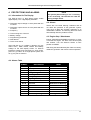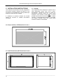
1
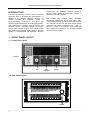
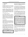
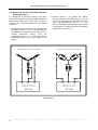
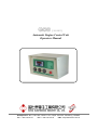
G08
( DC12V )
Automatic Engine Control Unit
Operators Manual
Headquarters : No.3, Lane 201, Chien Fu ST., Chyan Jenn Dist., Kaohsiung, TAIWAN
Tel : + 886-7-8121771
Fax : + 886-7-8121775
URL : http://www.kutai.com.tw
ECU-02
Ver2.1
Automatic Engine Control Unit
Operators Manual
Headquarters : No.3, Lane 201, Chien Fu ST., Chyan Jenn Dist., Kaohsiung, TAIWAN
Tel : + 886-7-8121771
Fax : + 886-7-8121775
URL : http://www.kutai.com.tw
ECU-02 Automatic Engine Control Unit Operators Manual
TABLE OF CONTENTS
Section
Page
INTRODUCTION ........................................................................................................................................ 3
1. FRONT PANEL LAYOUT ...................................................................................................................... 3
1.1 Front Panel Layout............................................................................................................................ 3
1.2 Rear Panel Layout ............................................................................................................................ 3
2. OPERATION .......................................................................................................................................... 4
2.1 Control............................................................................................................................................... 4
2.2 Auto Mode Of Operation ................................................................................................................... 4
2.3 Manual Mode Of Operation............................................................................................................... 5
2.4 Off Mode Of Operation...................................................................................................................... 6
3. PROGRAMMING INSTRUCTIONS ....................................................................................................... 6
3.1 Battery Voltage.................................................................................................................................. 6
3.2 Programming..................................................................................................................................... 6
3.3 Programming The Hour Meter .......................................................................................................... 7
3.4 Setting Up The Magnetic Pick-Up..................................................................................................... 7
3.5 Volts And Amps Readout Programming ........................................................................................... 7
3.6 Notice For The ECU-02 Is Working Over 400 Volts ( Line 3 ) .......................................................... 7
3.7 Generator Overload Protect Function ............................................................................................... 8
3.8 User Defined Inputs Alarm 1 To 4..................................................................................................... 8
3.9 Information On The Service Interval Display .................................................................................... 9
3.10 Display Mode Setting ...................................................................................................................... 9
3.11 Engine Test And Setup For Start / Stop --- Led Lamp Test.......................................................... 10
3.12 Line By Line Programming Table.................................................................................................. 10
4. PROTECTIONS AND ALARMS .......................................................................................................... 12
4.1 Information On The Display ............................................................................................................ 12
4.2 Alarms ............................................................................................................................................. 12
4.3 Engine Stop / Shutdowns................................................................................................................ 12
4.4 Alarms Table ................................................................................................................................... 12
5. INSTALLATION INSTRUCTIONS ....................................................................................................... 13
5.1 Cooling ............................................................................................................................................ 13
5.2 Panel Cut-Out ( All Dimensions In mm. ) ........................................................................................ 13
5.3 Unit Dimensions ( All Dimensions In mm. )..................................................................................... 13
6. ELECTRICAL CONNECTIONS ........................................................................................................... 14
6.1 Connection Details On The ECU-02 ............................................................................................... 14
6.2 Specification.................................................................................................................................... 15
7. FAULT FINDING .................................................................................................................................. 15
8. TYPICAL WIRING DIAGRAM IF ECU RELAY BOARD IS NOT USED ............................................. 16
______________________________________________________________________________________
3
ECU-02 Automatic Engine Control Unit Operators Manual
INTRODUCTION
The ECU-02 Generator Control module is used to
start and stop a generator-set automatically. In
addition to its automatic start-stop function, the
module monitors any problems related to
engine/generator performance and gives the
operator digital readouts for all working parameters.
The module will, by design, stop the engine and
diagnose engine / generator failures on a large,
easy-to-read 4 digit/7-segment front display panel
with flashing, light emitting diodes (LED’s). Remote
starting is accomplished via standard, two-wire
signals from any Automatic Transfer Switch or
remote switch. Model ECU-02 also includes a
generator overload protection.
The module also features easily adjustable
operational sequences, timers and alarm trips.
These customizations can be programmed easily by
the customer via the rear and front display panel.
These are the buttons ( PROM on rear, + and - on
the front ). There is no need for a PC connection
and programming software. Any and all changes
can be made in the field.
1. FRONT PANEL LAYOUT
1.1 Front Panel Layout
RESET
UP
KEY
SWITCH
DOWN
1.2 Rear Panel Layout
KUTAI ELECTRONICS INDUSTRY CO; LTD.
URL:http://www.kutai.com.tw
PROM.
______________________________________________________________________________________
4
ECU-02 Automatic Engine Control Unit Operators Manual
After the above start delays, the Fuel Solenoid and
Starter Motor are energized. The display will
indicate “ St.XX ”, and the Starter cranking timer will
count down on the front display panel.
2. OPERATION
2.1 Control
The ECU-02 is controlled by using the front display
panel Selector Switch (See 1.1). There are only
three positions from which to choose : AUTO, OFF
and MANUAL. The Selector Switch is the only
control you need to operate the generator.
The Selector Switch is framed by two small
push-buttons, − (DOWN)/ + (UP) (See 1.1). These
buttons access more complex information, such as
Voltage VOLT and Amperage AMP on each phase
L1-2, L2-3, L3-1, FREQ in Hertz, HOUR hour meter,
BATT battery voltage, and remaining time until next
service. These functions are described in greater
detail in section 3.9 ~ 3.11.
2.2 Auto Mode Of Operation
With the Selector Switch on the “ Automatic ”
position, the ECU-02 controls all the functions of the
generator-set. The two Remote Start Inputs ( see
1.2 terminals 15 and 16 ) on the ECU-02 are
monitored constantly. Once the start condition is
signaled by an Automatic Transfer Switch or a
remote start switch, the ECU-02 commences the
start sequence. The generator automatically is then
placed on load.
AUTO SEQUENCE :
The flashing AUTO LED on the front panel ( see 1.1 )
indicates, at a glance, that the generator-set is on
stand-by and ready to start. When a Remote Start
signal is given by the ATS, the AUTO LED stops
flashing, indicating that the engine is on start
countdown and will start.
If the engine needs Pre-heat and this option is
selected, the ECU-02 starts pre-heating the engine,
and the corresponding relay output is energized.
The front display will read “ Ph.XX ”, and the
Pre-heat timer will count down the seconds on the
front panel. Setting 0 ( NO Pre-heat ) on the
programming sequence will set an automatic 5
second engine start delay before starting the engine.
( The display will indicate “ 05 ” ) For additional
instruction on programming. ( See 3.12 )
NOTE
If the Remote Start signal is removed during
the Pre-heat Delay, the unit will return to a
stand-by state after the Stop period.
The engine cranks for a pre-programmed time
period. Should the engine fail to start during these
first cranking attempts, the starter motor disengages,
and the engine goes into pre-heat again. Should this
sequence go beyond the set number of start
attempts, starting will be terminated, and the start
fault alarm will be displayed by a flashing “ AL.00 ”
on the front panel.
After the engine starts, the starter motor is
automatically disengaged by sensing 1, or as may
as 3, different signals from the engine. These
signals are : (1) a pre-set frequency ( 20% of rated
frequency ); (2) output voltage from the generator,
and (3) oil pressure switch signal from the engine
and/or the signal from the Magnetic Pick-Up. Any
one or up to all three signals can be use to
disengage the starter motor.
NOTE
If you program the oil pressure switch to
disconnect the starter, you may get a false
oil pressure reading, giving you premature
starter disconnect and tricking the ECU to
believe the engine is running. (For example:
when testing the engine with repeated starts;
when the engine is cool and the crankcase
oil is thick; and certain types of engines that
build UP oil pressure quickly before engine
start). If this is the case, remember that you
have other programmable choices for
disengaging the starter that are equally as
effective.
After the starter disengages and the engine is
running normally, a grace period is activated. This
grace period allows oil pressure, engine speed,
voltage and any other delayed Auxiliary inputs to be
stabilized, before monitoring and triggering any
faults ( if any ).
After the engine is running, the Engine Warm UP
timer, if selected, is initiated. The Warm UP timer
allows the engine to warm up and stabilize before
accepting any loads. A signal is given to a load
transfer contactor to activate and take up the load.
( BE AWARE that some generators sets have no
Load Contactor )
______________________________________________________________________________________
5
ECU-02 Automatic Engine Control Unit Operators Manual
NOTE
A load transfer output will not be initiated
until the Oil Pressure, Engine Speed and
alternating voltages have risen and are all
normal.
With the return of normal power, the ATS removes
the Remote Start signal. The load transfer contactor
is the first to be de-energized, removing the load
and initiating the engine Cool Down phase (engine
with no load). The display will indicate “ CL.XX ”,
and the Cool Down delay timer will count down on
the front display panel.
Please be aware if your ATS also includes the
above mentioned sequences. If so, then your timed
sequences will run concurrently, combining the time
programmed. For example, if you have a sixty
second cool-down on an ATS and sixty second
cool-down programmed on the ECU-02, your total
cool-down will be 120 seconds.
To avoid this redundancy, set the ECU-02 timing
delays ( i.e. warm-up, cool-down ) to 0 if your ATS
includes these functions.
After the Cool-Down times out, the Fuel Solenoid is
( de-energized or energized as the case may be )
bringing the generator to a stop. The front display
will indicate “ SP.XX ”, and the Stop delay timer will
count down on the front panel. The ECU will reset,
and the remote start LED will start flashing,
indicating the generator is on standby and ready to
start.
2.4 Off Mode Of Operation
The OFF position places the module into its Stop or
Reset mode. This will clear any alarm conditions for
which the triggering criteria have been removed.
If the engine is running and this position is selected,
the module will automatically shut down the
generator. The fuel supply will be removed and
engine will be brought to a standstill. Should a
remote start signal be present while operating in this
mode, a remote start will not occur.
3. PROGRAMMING INSTRUCTIONS
NOTE
Further programming and configuration
must be made with the ECU-02 installed and
connected to the battery.
3.1 Battery Voltage
The ECU-02 engine control unit automatically
adjusts itself to DC12 or DC24 volts systems. When
cranking, voltages drop sometimes to levels ( under
6Vdc ) that may render the ECU ineffective, due to a
low or defective battery. Install new batteries or fix
the starter. If the unit freezes because of low
cranking voltage, it may be reset by: disconnecting
B- from the battery for 4 seconds; or, you can simply
push the reset button behind the front panel with a
thin isolation tool for 1 second. ( See 1.1 for front
panel layout )
3.2 Programming
Should the Remote start signal be re-activated
during the cooling down period, the set will
immediately return to load.
2.3 Manual Mode Of Operation
Manual operation is conducted by turning the
Selector Switch to Manual on the front display panel
( See 1.1 ) The start sequence is the same as in the
AUTO MODE sequence of operation ( See 2.2
above ). Turning the Selector Switch to OFF stops
the engine after cool-down. In Manual the MANU
LED is illuminated.
NOTE
With the Selector Switch on OFF, push the button
“ PROM ” on the rear panel of ECU-02 for 4 seconds.
The word “ Ver 2.1 ” will appear on the front display
for 2 seconds. This number indicates the version of
the software. After that, the word “ Pro. ” will appear
on the front panel for 4 seconds.
You are now ready to start a line by line
programming sequence. To advance to the next
line, push the PROM button on the back panel.
( See 1.2 )
Use the UP (+) and DOWN (-) buttons, to change
each line’s programming parameters.
In manual mode of operation, the ATS will
not operate the ECU-02. Remote start is
disabled.
______________________________________________________________________________________
6
ECU-02 Automatic Engine Control Unit Operators Manual
Always push the “ PROM ” button to advance to next
programming line or until the word “ END ” appears
on the screen. To immediately end the programming
mode, you can simply push the “ PROM ” button for
4 seconds at any time. The word END on the front
display panel indicates a return to previous settings.
3.5 Volts And Amps Readout Programming
Should you make an error or desire to return to
factory settings, stay in “ Pro. ” mode and
simultaneously press all 3 buttons : UP (+), DOWN
(-) and PROM for 4 seconds. The ECU-02 will now
automatically program itself to factory settings and
the word “ Au.Po ” will appear on the display. ( See
table 3.12 for ECU-02 factory settings.)
For example: If the ECU reads 200 Volts but your
“ Calibrated Mete ” reads 205 volts, you can easily
add 5 volts to the ECU readout by putting the
number 5 on line 2. The next time you start the
generator, 5 is automatically added, reading 205
volts on the ECU.
3.3 Programming The Hour Meter
Programming lines 2 & 7 are used for fine
calibration of the VOLTS & AMPS readout. This
option is used only if you have a “calibrated service
meter” that you want to synchronize with the
readings from the ECU-02.
To achieve the same synchronization for amperage
AMPS, program line 7 to desired level.
Turn the Selector Switch to the OFF position. Push
the “ PROM ” button on the rear panel until the word
“ Pro. ” appears on the screen. Push the “ UP(+) ”
key one time quickly before the word “ Pro. ”
disappears. The front display will read “ Ch.Hr ”
indicating the operating hours of the gen-set. To
reconcile the ECU-02 with the gen-set’s hours ( For
example, to set the ECU-02 at 200 hours to match a
gen-set with 200 previous operating hours ), push
the UP (+) and DOWN (-) buttons to the number of
hours desired.
After resetting the hour meter, simply push the
PROM button again. The word “ END ” on the panel
indicates that you are back to normal operating
mode.
3.4 Setting Up The Magnetic Pick-Up
Prior to setting the magnetic Pick-Up ( Refer table
3.12 ), you must program lines 12, 13, 14, 15 and 19.
Then, start the engine and run it at normal speed
( 50 or 60 Hz ).
Next, set the LED on the front display panel next to
FREQ, using the UP (+) and DOWN (-) buttons.
When 50 or 60Hz appears on the LED, push the
PROM button for one second, and “ Pro. ” will
appear. If “ FAIL ” appears, check the MPU wires
and installation and try again.
The ECU-02 is now programmed with an
over-speed trip, using the Magnetic Pick-Up that is
dependent on the settings for line 14 ( 105%, 110%,
115% or 120% above rating speed ), plus a 20%
automatic starter motor disconnect. If any wires on
the Magnetic Pick-Up break, the ECU-02
automatically shuts down the engine and shows the
flashing alarm signal “ AL.02 ” on the front screen.
______________________________________________________________________________________
7
ECU-02 Automatic Engine Control Unit Operators Manual
3.6 Notice For The Ecu-02 Is Working Over
400 Volts ( Line 3 )
It is dangerous to feed high voltage to the ECU
Printed Circuit boards. The highest input voltage the
ECU-02 can safely read is 400 volts. To work at
over 400 volts, we have developed two clear, simple
methods :
1. One approach is to use the 1 to ½ transformer
provided ( Part N0. PTU-03 ). Feed 480 volts into
the transformer input and connect the ECU to ½
voltage
transformer
output.
Then
set
programming line 3 to “1.” Now, the ECU-02
automatically doubles the input voltage on the
display.
2. Another method is to connect the voltage
sensing wires to the first Star, using lines T7, T8
& T9 on the generator ( See diagram 3.6 below ).
Next, set programming line 3 to “1.” The
ECU-02 automatically doubles the input voltage
on the display. ( Using this method, the Isolating
transformers remain 1 to 1 )
Working with 380 to 480 volts Generator
L1
T2
T1
T4
Working with 208 to 240 volts Generator
L2
L1
T2
T7
T5
T7
T10
L2
T5
T8
T10 T11
T8
T1
T4
T11
T12
T9
T12
T6
T6
T9
T3
T3
L3
L3
PIN7
PIN3
PIN5
PIN7
Setting line 3 to yes (1)
Read-out volt = input volts * 2
PIN3
PIN5
Setting line 3 to no (0)
Read-out volt = input volts * 1
ECU-02
ECU-02
DIAGRAM 3.6
______________________________________________________________________________________
8
ECU-02 Automatic Engine Control Unit Operators Manual
3.7 Generator Overload Protection Function
The function of the Generator overload protector is
to STOP the engine if it is overworked by the
customer, or if the engine goes over a given
“ Amps ” set point established by the generator
operator. This setting is easily changed, and it has
adequate delays to compensate for temporary
normal overloads.
Current Transformer Connection
( Correct and ONLY schema for CT connection )
DIAGRAM 3.7
NOTE
NOTE
Wire each CT individually into the ECU-02.
Do not Daisy Chain or Ground any CT.
Never set line 9 to a value larger then the CT
(current transformer) correctly inside the
generator. For example if we are using
1000/5A CTs, line 9 can not be programmed
to a value larger 20 x 50 ( 1000amps ), etc.
( See Diagram 3.7 )
When the ECU-02 detects a overload above the set
point and this overload continues over the delay
time set by line 10, the ECU-02 will shutdown the
engine and show “ AL.07 ” alarm on the front panel.
To reprogram a cut-off point, go to line 9 and select
a power unit needed. Programming 1 power unit into
line 9 is equal to 50 Amps of load ( 1 power unit = 50
amps ). For example, programming line 9 with 20
units represents an overload cut off current of 1000
Amps (50*20=1000)
______________________________________________________________________________________
9
ECU-02 Automatic Engine Control Unit Operators Manual
3.8 User Defined Inputs Alarm 1 To 4
The ECU-02 provides four alarm inputs, which can
be defined by the user for any function. These alarms
may be defined to provide warnings or shut-downs to
the engine. Sensors can be closed or open signals,
as defined by the user. To set the alarms, see
programming table 3.16, lines 34 to line 42.
All four alarms/sensors are the same except for
Alarm 1. This first alarm provides the user a time
delay function. You can set the delay response time
on alarm 1 from 0 to 99 Seconds, using
programming line 36. Alarms 2, 3 and 4 respond
immediately, with no delay.
3.9 Information On The Service Interval
Display
The engine service reminder is programmed into
line 43 and can be set to ( 0 to 990 hours ) hours. To
program the hours between services, press the
PROM. button and go to line 43. Using the - (DOWN)
/ + (UP) buttons, select the number of hours desired.
Each integer represents ten hours. ( For example,
setting the number 2 will program a reminder of
twenty hours; Setting the number 40 will program a
service interval of 400 hours.) If the HOUR LED
starts flashing, this is your reminder to give service
to the generator set and, afterwards, reset the
service meter. Setting the hour to 0 will not provide a
maintenance reminder.
Programming line 44 to 0 allows you to view the
specific parameters without scrolling. You can
change the display by simply pressing the - (DOWN)
/+ (UP) buttons
3.11 Engine Test And Setup For Start / Stop
--- Led Lamp Test
When testing and/or setting up your engine with the
ECU-02 for the first time, you can override any
engine STOP Commands, thus enabling you to set
up engine parameters without the engine stopping
every time and interrupting your work. This tool is
very helpful when troubleshooting or when adjusting
voltages and engine governors on a new engine.
Remember; it is very important to preprogram line
24 correctly for Energize to STOP or Energize to
START for your engine type, before using this
handy tool.
Programming line 45 to 1 allows you to manual start
and stop the engine by pressing the (+) key to start
and (-) key to STOP. When you are using this tool
all the LED’s on the panel are lit, so that you may
also test all the LED lamps.
When finished utilizing the Engine override function,
push the PROM. button one time and the word
“ END ” will appear on the front display. The
ECU-02 will return Line 45 to 0 automatically.
To reset the service meter, set the LED to HOUR by
pressing the - (DOWN) / + (UP) keys on the front
display. Next, push the PROM. button on back panel
for 1 second. The ECU-02 is now reset and ready to
remind you of your next engine service.
3.10 Display Mode Setting
The ECU-02 provides two display modes. The user
has the option to view the entire system’s operating
parameters ( Voltage, Amps, Frequency, Hour
meter and DC Voltage ) scrolled on the front display
or one parameter at a time.
Programming line 44 to 1 allows you to view the
voltage, amps and frequency parameters for each
phase in rotation automatically. Each parameter will
show on the front display for 2 sec and change to
the next. In this mode, the ECU-02 allows you to
STOP the scrolling to view specific parameter for 30
seconds, by pressing the - (DOWN) or + (UP)
buttons. The ECU returns to automated scrolling
after 30 seconds.
______________________________________________________________________________________
10
ECU-02 Automatic Engine Control Unit Operators Manual
3.12 Line By Line Programming Table
ITEM
DESCRIPTION
SETTING
0
1
Is this generator operating in 3 phase or 1 phase?
0 3 Phase
2
Fine calibration of Voltage read-out ( Refer to chapter 3.5 )
-50V ~ 50V
3
If the ECU is going to work over 400 volt?
If Yes, go to chapter 3.6 and read related information
0 No
(0= volt * 1
4
Set Under Voltage by setting a number from 16 to 47. (# * 10)
16 ~ 47 (160 ~ 470 V.)
For example, the number 18 represent 180 volts, etc
18
(180V)
5
Set Over Voltage by setting a number from 23 to 55. (# * 10)
For example, the number 25 represent 250 volts, etc
25
(250V)
6
Time before Generator STOPs, if there is a problem with the 0 ~ 60 sec
generator voltage output
( 0 – No alarms )
15
7
Calibrate the AMPS read-out ( Refer to chapter 3.5 )
-50A ~ 50A
0
Tell ECU-02 what CT ( Current Transformer ) is going to be
installed
1 25/5
4 75/5
7 200/5
10 400/5
13 750/5
16 1200/5
19 2000/5
8
For example, if installing a 100/5A CT, program the number 5
into ECU-02, etc
1 1 Phase
FACTORY
SETTING
0
1 Yes
1= volt *2)
23 ~ 55 (230 ~ 550 V.)
2 50/5
3 60/5
5 100/5
6 150/5
8 250/5
9 300/5
11 500/5 12 600/5
14 800/5 15 1000/5
17 1500/5 18 1600/5
20 3000/5
5
2(100A)
9
Overload setting ( Refer to chapter 3.7 )
10
Time before Generator STOPs if there is a problem with the 0 ~ 99 sec
generator overload
( 0 – No alarms )
11
At what frequency “ Hertz ” will generator operate?
0 60 Hz
1 50 Hz
0
12
Test for Over-speed?
0 No
1 Yes
1
13
Test Over-speed using the generator output or Magnetic 0 Generator
Pick-Up
1 Magnetic Pick-Up
14
Over-speed shutdown setting
1 ~ 60 (50 – 3000A )
0
1 105%
3 115%
3
2 110%
4 120%
0
4
15
Time before Generator STOPs, if there is a problem with
0 ~ 60 sec
generator frequency output
5
16
Time to set Pre-Heat of engine
0 ~ 30 sec ( 0 – No Pre-Heat )
10
17
Number of start attempts
1~9
3
18
Time to run the engine starter with each engine start.
2 ~ 30 sec
6
19
Remove starter by using the Magnetic Pick-up?
0 No
1 Yes
0
20
Remove starter by using engine oil pressure sensor?
0 No
1 Yes
0
21
Low oil pressure switch
Normally Open (NO) or normally close (NC)
0 NO
1 NC
1
22
Time before Generator STOPs, if there is a problem with low 0 ~ 60 sec
oil pressure
( 0 – No alarms )
10
23
Time to Energize to STOP the fuel solenoid
15
24
Is the STOP fuel Solenoid : Energize to STOP or Energize to 0 Energize to STOP
START
1 Energize to START
2 ~ 60 sec
1
______________________________________________________________________________________
11
ECU-02 Automatic Engine Control Unit Operators Manual
ITEM
DESCRIPTION
SETTING
FACTORY
SETTING
25
Time for engine cool-down without load
0 ~ 60 min
0
26
If a load contactor is used, time allowed for engine warm-up 0 ~ 99 sec
before connecting the LOAD
0
27
Temperature switch
Normally Open (NO) or normally closed (NC)
28
Time before Generator STOPs, if there is a problem with 0 ~ 60 sec
engine temperature
( 0 – No alarms )
29
Enable or disable the alarm output (pin 24)
0 Disable
1 Enable
0
30
Emergency STOP button
Normally Open (NO) or normally closed (NC)
0 NO
1 NC
1
31
Overload sensor
Normally Open (NO) or normally closed (NC)
0 NO
1 NC
0
32
Low fuel sensor
Normally Open (NO) or normally closed (NC)
0 NO
1 NC
0
33
Low Engine fuel
0 Warning
1 Stop
0
34
Alarm 1
0 NO
1 NC
0
35
Alarm 1 input
0 Warning
1 Stop
0
36
Time delay when alarm 1 input (Refer to chapter 3.8)
0 ~ 99 sec. ( 0 – No alarms )
0
37
Alarm 2
0 NO
1 NC
0
38
Alarm 2 input
0 Warning
1 Stop
0
39
Alarm 3
0 NO
1 NC
0
40
Alarm 3 input
0 Warning
1 Stop
0
41
Alarm 4
0 NO
1 NC
0
42
Alarm 4 input
0 Warning
1 Stop
0
Engine service interval reminder ( Refer to chapter 3.9 )
0 ~ 99 ( 0 ~ 990 H )
(0 –No maintenance )
0
44
Display mode setting (Refer to chapter 3.10)
0 Fix
1
45
Is the generator working in TOOL mode?
Warning : No Safety shutdowns on TOOL Mode
Also LED Lamp Test ( Refer to chapter 3.11 )
0 NO say Normal
1 YES, Tool Mode
43
Normally Open (NO) or normally closed (NC)
Normally Open (NO) or normally closed (NC)
Normally Open (NO) or normally closed (NC)
Normally Open (NO) or normally closed (NC)
0 NO
1 NC
0
5
1 Rotation
0
______________________________________________________________________________________
12
ECU-02 Automatic Engine Control Unit Operators Manual
4. PROTECTIONS AND ALARMS
4.1 Information On The Display
The ECU-02 has a 4 digit display easily visible
digital display. The 4 digit display indicates:
● Generator output voltage on each phase with the
± buttons
● Generator output current on each phase with the
± buttons
● Frequency
● Total running hour “Service”
● Battery voltage
NOTE
Set system phase setting in line 1 correctly.
If set incorrectly, the ECU-02 will read the
wrong voltage values.
4.2 Alarms
Alarms are non-critical warning conditions and do
not affect the operation of the generator system.
They serve to draw the operator’s attention to an
undesirable condition. The warning alarm will reset
automatically after the problem is fixed.
4.3 Engine Stop / Shutdowns
● Programming parameter
● Fault alarms
● Timer count downs
Using with the Up (+) / DOWN (-) buttons you may
select VOLT, AMP, FREQ, HOUR and Battery
Voltage on the front display screen. To observe
individual Voltage and Amperage on each phase,
press UP (+) button. On a single phase system, the
UP (+) key has no function.
Engine STOPS/SHUTDOWNS are latching, or final.
To restart the engine, the alarm must be accepted
and cleared. Turn the Selector Switch to OFF
position to RESET.
After fixing the fault indicated (See Table 4.4 below),
restart the generator and resume normal operation.
4.4 Alarms Table
SYMBOL
DISCRIPTION
AL 00
AL 01
AL 02
AL 03
AL 04
AL 05
AL 06
AL 07
AL 08
AL 09
AL 10
AL 11
AL 12
AL 13
Engine Start Failure
Over Speed
Magnetic Pick-Up Defective
Wrong Voltage
Low Engine Oil Pressure
Emergency STOP Pushed
High Engine Temperature
Generator Over Loaded
Low Fuel
Option 1
Option 2
Option 3
Option 4
Low Battery Voltage
LEVEL
Shut Down
Shut Down
Shut Down
Shut Down
Shut Down
Shut Down
Shut Down
Shut Down or Warning
Shut Down or Warning
Shut Down or Warning
Shut Down or Warning
Shut Down or Warning
Warning
______________________________________________________________________________________
13
ECU-02 Automatic Engine Control Unit Operators Manual
5. INSTALLATION INSTRUCTIONS
5.1 Cooling
The model ECU-02 Module has been designed for
front panel mounting. Affixing the ECU-02 to the
front panel is accomplished by 2 spring loaded clips
located on each side of the module.
The module has been designed to operate over a
wide temperature range, from -25 to +55ºC.
Nevertheless, allowances should be made for
temperature increases within the control panel
enclosure. Care should be taken NOT to mount
possible heat sources near the module ( i.e., battery
chargers ), unless adequate ventilation is provided.
The relative humidity inside the control panel
enclosure should not exceed 85%.
In conditions of excessive vibration the module
should be mounted on suitable anti-vibration
mountings.
5.2 Panel Cut-Out ( All Dimensions In mm. )
5.3 Unit Dimensions (All Dimensions In mm.)
______________________________________________________________________________________
14
ECU-02 Automatic Engine Control Unit Operators Manual
6. ELECTRICAL CONNECTIONS
6.1 Connection Details On The ECU-02
PLUG “ J1 ” 18 WAY
PIN No.
1
2
3
4
5
6
7
8
9
10
11
12
13
14
15
16
17
18
DESCRIPTION
Not Used
Not Used
Generator L3 sensing input.
Not Used
Generator L2 sensing input.
Not Used
Generator L1 sensing input.
Not Used
CT secondary for L3
CT secondary for L3
CT secondary for L2
CT secondary for L2
CT secondary for L1
CT secondary for L1
Remote start input
Remote start input
DC Plant Supply Input (-v)
DC Plant Supply Input (+v)
NOTES
Spare
Spare
Connect to alternator L3 output.
Spare
Connect to alternator L2 output.
Spare
Connect to alternator L1 output.
Spare
Connect to secondary of L3 monitoring CT.
Connect to secondary of L3 monitoring CT
Connect to secondary of L2 monitoring CT
Connect to secondary of L2 monitoring CT
Connect to secondary of L1 monitoring CT
Connect to secondary of L1 monitoring CT
Connect to A.T.S device
Connect to A.T.S device
System DC negative input. (Battery Negative).
System DC positive input. (Battery Positive).
Recommended fuse 2 Amp
PLUG “ J2 ” 18 WAY
PIN No.
DESCRIPTION
19
Warm up signal Output
20
Fuel solenoid signal Output
21
Start signal Output
22
23
Auxiliary signal Output
Pre-heat signal Output
24
Alarm signal Output
25
26
27
28
29
30
31
32
33
34
35
Emergency Stop Input
Oil Pressure Input
Coolant Temperature Input
Overload sender Input
Low fuel sender Input
Auxiliary Input 1
Auxiliary Input 2
Auxiliary Input 3
Auxiliary Input 4
Not Used
Magnetic Pick-Up Input (+v)
36
Magnetic Pick-Up Input (-v)
NOTES
Used to control the Warm UP contactor. Supply
(-v) 2.5 Amp rated
Used to control the fuel solenoid or engine fuel
control system. Supply (-v) 2.5 Amp rated
Used to control the Starter Motor. Supply (-v) 2.5 Amp
rated
Energize to start. Supply (-v) 2.5 Amp rated
Used to control the internal Heater Supply (-v) 2.5
Amp rated
Used to control external alarm buzzer. Supply (-v) 2.5
Amp rated
Connect to external emergency stop switch
Connect to Oil pressure sender
Connect to Coolant Temperature sender
Connect to Overload sender
Connect to fuel sender
This is a negative switched configurable input
This is a negative switched configurable input
This is a negative switched configurable input
This is a negative switched configurable input
Spare
Connect to Magnetic Pick-Up device. AC signal from
the magnetic pickup for speed sensing
Connect to Magnetic Pick-Up device. AC signal from
the magnetic pickup for speed sensing
______________________________________________________________________________________
15
ECU-02 Automatic Engine Control Unit Operators Manual
6-2 Specification
DC Supply
Alternator Input Range
Alternator Input Frequency
Magnetic Input Range (if fitted)
Magnetic Input Frequency
Warm up Signal Output
Fuel solenoid Signal Output
Start Signal Output
Pre-heat Signal Output
Auxiliary Signal Output
Alarm Signal Output
Operating Temperature Range
CT Burden
CT Secondary
9.0 to 30 V Continuous.
15V - 380 (ph-ph) 3 Phase 3wire AC (+15%)
50 ~ 60 Hz at rated engine speed
+/- 2V to 70V Peak
10,000 Hz (max) at rated engine speed
5 Amp DC at supply voltage
5 Amp DC at supply voltage
5 Amp DC at supply voltage
5 Amp DC at supply voltage
5 Amp DC at supply voltage
5 Amp DC at supply voltage
-25 to +55 °C
2.5VA
5A
7. FAULT FINDING
SYMPTOM
ECU-02 is inoperative
Engine Shuts Down
Engine locks out on Emergency
Stop
Intermittent Magnetic Pick-up
sensor engine shutdown
Low Oil Pressure shutdown after
engine has started
High engine temperature shutdown
after engine has started
Shutdown occurs
Alarm occurs
Engine fail to Start despite
pre-set number of attempts
POSSIBLE REMEDY
Check if the emergency stop is push on.
Check the battery and wiring to the unit.
Check Battery Volts on cranking. ( not below 6V )
Check the DC fuse F5 and F6.
Check DC supply voltage is not below 6 Volts.
Check that operating temperature is not above 55 °C.
If the Emergency Stop Button is not used, program line 24 to NO =0
Check emergency stop switch is functioning correctly.
Check Wiring is not open circuit.
Check line 24 setting is correct.
Check magnetic pick-up is functioning correctly.
Check Wiring is not open circuit.
Check output voltage is not below less de 8 Volts RMS.
Check engine oil pressure.
Check oil pressure switch / sender and wiring.
Check configured polarity is correct ( i.e. NO or NC )
Check engine temperature.
Check switch / sender and wiring.
Check configured polarity is correct ( i.e. NO or NC )
Check switch and wiring of fault indicated on display.
Check configuration of input.
Check relevant switch and wiring of fault indicated on display.
Check configuration of input.
Check fuel.
Check wiring of fuel solenoid.
Check battery supply.
Check the speed sensing signal is present on the inputs.
Check that the “ Remote Start ” input is not shorted.
Continuous starting of generator
when in AUTO
Generator fails to start on receipt Check if engine Start Delay timer has timed out.
of Remote Start signal.
If remote start faults, check if signal is on “ Remote Start ” input.
Pre-heat inoperative
Check wiring to engine heater plugs.
Check that pre-heat has been selected in your program.
Starter motor inoperative
Check wiring to starter solenoid.
Check starter motor. You have a 30 Amp limit.
Engine runs but generator will not Check if warm up timer has timed out.
take load
Check warm up has been selected in your configuration.
______________________________________________________________________________________
16
ECU-02 Automatic Engine Control Unit Operators Manual
8. TYPICAL WIRING DIAGRAM
L3
L2
L3
L2
L1
GEN-SET
N
ECU-02
5
7
2A
3
2A
2A
9
10
11
15
12
16
13
17
14
2A
BATTERY
36
Remote Start
From ATS Panel
35
Meganetic
Pick-up
33
Alarm 4
32
Alarm 3
31
Alarm 2
30
Alarm 1
29
Low Fuel Sensor
28
Overload Sensor
27
High Temperature
26
Low Oil Pressure
25
Pin 3 & 9 & 10 & 11 &12 is not use for single phase system
Emergency Stop
18
19
Warm Up
Contactor
L1
N
LOAD
24
Alarm
23
Pre-Heat
22
Auxiliary
21
Starter
20
30A
+
Stop
______________________________________________________________________________________
17
ECU-11(12V) & ECU-22(24V)
Relay Module And Harness
For Quick Installation of ECU
Headquarters : No.3, Lane 201, Chien Fu ST., Chyan Jenn Dist., Kaohsiung, TAIWAN
Tel : + 886-7-8121771
Fax : + 886-7-8121775
URL : http://www.kutai.com.tw
ECU-11 (12V) & ECU-22 (24V) Relay Module
ECU-11 (12V) & ECU-22 (24V) RELAY
MODULE OPERATORS MANUAL
1. Introduction
The Relay Module is the interface between the
automatic engine control module ECU-02 and the
generator. The ECU-11 & ECU-22 provides two 18
ways plugs to connect to ECU-02 module. All the
protected fuses and power relays for engine
pre-heat, start, fuel, stop, and alarm output are
pre-assembled on the relay module. Simply connect
the control wires to the correct terminals on the
module, thus minimizing assembly time and
potential for errors when assembling and installing
the engine control wires.
2. ECU-11(12V) & ECU-22(24V) Connection Details
1. The plug J1 ( Pin1 ~ Pin18 ) connected to the plug J1 of ECU-02.
2. The plug J2 ( Pin19 ~ Pin36 ) connected to the plug J2 of ECU-02.
2.1 Terminal TB2 Power And 30 Amp Output Connections
PIN NO.
DESCRIPTION
TB2-1 DC Plant Supply Input (-v)
TB2-2 DC Plant Supply Input (+v)
TB2-3 Fuel solenoid signal output
Programmable to ET STOP or
ET START
TB2-4 Start signal output
TB2-5 Pre-heat signal output
NOTES
System DC negative input. (Battery Negative). AWG10
System DC positive input. (Battery Positive). AWG10
Controls the fuel solenoid or engine fuel control system.
Supply (+v) 30 Amp rated.
Controls the Starter Motor. Supply (+v) 30 Amp rated.
Controls the engine pre heater Supply (+v) 30 Amp rated.
______________________________________________________________________________________
19
ECU-11 (12V) & ECU-22 (24V) Relay Module
2.2 Terminal TB3
PIN NO.
TB3-1
TB3-2
TB3-3
TB3-4
TB3-5
TB3-6
TB3-7
TB3-8
TB3-9
TB3-10
TB3-11
TB3-12
TB3-13
TB3-14
TB3-15
TB3-16
TB3-17
DESCRIPTION
Generator L3 sensing input
Not Used
Generator L2 sensing input
Not Used
Generator L1 sensing input
Not Used
Warm up signal Output
Warm up signal Output
CT secondary for L3
CT secondary for L3
CT secondary for L2
CT secondary for L2
CT secondary for L1
CT secondary for L1
Remote start input
Remote start input
Auxiliary signal Output
TB3-18
TB3-19
TB3-20
TB3-21
TB3-22
TB3-23
TB3-24
TB3-25
TB3-26
TB3-27
TB3-28
TB3-29
Alarm signal Output
Emergency Stop Input
Oil Pressure Input
Coolant Temperature Input
Overload sender Input
Low fuel sender Input
Auxiliary Input 1
Auxiliary Input 2
Auxiliary Input 3
Auxiliary Input 4
Not Used
Magnetic Pick-up Input (+v)
TB3-30
Magnetic Pick-up Input (-v)
NOTES
Connect to alternator L3 output.
Spare.
Connect to alternator L2 output.
Spare.
Connect to alternator L1 output.
Spare.
Used to control the Warm up contactor. 5 Amp rated.
Used to control the Warm up contactor. 5 Amp rated.
Connect to secondary of L3 monitoring CT.
Connect to secondary of L3 monitoring CT.
Connect to secondary of L2 monitoring CT.
Connect to secondary of L2 monitoring CT.
Connect to secondary of L1 monitoring CT.
Connect to secondary of L1 monitoring CT.
Connect to A.T.S remote start contact.
Connect to A.T.S remote start contact.
Energize to start. (+v) 5 Amp rated. (Not Programmable) for
use with Electronic Governors, Battery charging alternator
exciter. Etc.
For use with an external alarm. Supply (+v) 5 Amp rated.
Connect to external emergency stop switch. (Panic Button)
Connect to Oil pressure sender.
Connect to Coolant Temperature sender.
Connect to Overload sender.
Connect to low fuel indicator switch sensor.
This is a negative switched configurable input with time out.
This is a negative switched configurable input.
This is a negative switched configurable input.
This is a negative switched configurable input.
Spare.
Connect to Magnetic Pickup device.
AC signal from the magnetic pick-up for speed sensing.
Connect to Magnetic Pickup device.
AC signal from the magnetic pick-up for speed sensing.
______________________________________________________________________________________
20
ECU-11 (12V) & ECU-22 (24V) Relay Module
3. ECU-11(12V) & ECU-22(24V) Typical Wiring Diagram
ECU-02 Connect Wire Diagram With ECU-11 or ECU-22 (Relay Board)
______________________________________________________________________________________
21
PTU-03
Transformer Unit : PTU-03
ECU Voltage Isolation
Headquarters : No.3, Lane 201, Chien Fu ST., Chyan Jenn Dist., Kaohsiung, TAIWAN
Tel : + 886-7-8121771
Fax : + 886-7-8121775
URL : http://www.kutai.com.tw
Transformer Unit : PTU-03
TRANSFORMER UNIT : PTU-03 (OPTION)
F1
F2
F3
2
1
2
PT1
3
1
2
3
1
2
PT2
TRANSFORMER UNIT: PTU-03
3
3
Rated(Max)
1
TB4
Status
600VAC
TB3
Pin NO.
Input
1
TB2
TB1
Output
0.583
TB1
TB2
Output
0.5
Volt Ratio
TB3
Output
1
TB4
TB2-3
TB1-2
TB1-3
L1
L2
L3
GENERATOR
Working with 208 ~ 240 volts generator
PS : Set the programming line 38 to "0"
PIN7
TB2-2
TB1-1
PTU-03
PIN5
TB2-1
ECU-01
PIN3
TB4-3
TB1-2
TB1-3
L1
L2
L3
GENERATOR
Working with 380 ~ 480 volts generator
PS : Set the programming line 38 to "1"
PIN7
TB4-2
TB1-1
PTU-03
PIN5
TB4-1
ECU-01
PIN3
______________________________________________________________________________________
23