1
TMS320C6000 Imaging Developer’s Kit
(IDK)
User’s Guide
Literature Number: SPRU494A
September 2001
Printed on Recycled Paper
IMPORTANT NOTICE
Texas Instruments Incorporated and its subsidiaries (TI) reserve the right to make corrections,
modifications, enhancements, improvements, and other changes to its products and services at
any time and to discontinue any product or service without notice. Customers should obtain the
latest relevant information before placing orders and should verify that such information is current
and complete. All products are sold subject to TI’s terms and conditions of sale supplied at the
time of order acknowledgment.
TI warrants performance of its hardware products to the specifications applicable at the time of
sale in accordance with TI’s standard warranty. Testing and other quality control techniques are
used to the extent TI deems necessary to support this warranty. Except where mandated by
government requirements, testing of all parameters of each product is not necessarily performed.
TI assumes no liability for applications assistance or customer product design. Customers are
responsible for their products and applications using TI components. To minimize the risks
associated with customer products and applications, customers should provide adequate design
and operating safeguards.
TI does not warrant or represent that any license, either express or implied, is granted under any
TI patent right, copyright, mask work right, or other TI intellectual property right relating to any
combination, machine, or process in which TI products or services are used. Information
published by TI regarding third party products or services does not constitute a license from TI
to use such products or services or a warranty or endorsement thereof. Use of such information
may require a license from a third party under the patents or other intellectual property of that third
party, or a license from TI under the patents or other intellectual property of TI.
Reproduction of information in TI data books or data sheets is permissible only if reproduction
is without alteration and is accompanied by all associated warranties, conditions, limitations, and
notices. Reproduction of this information with alteration is an unfair and deceptive business
practice. TI is not responsible or liable for such altered documentation.
Resale of TI products or services with statements different from or beyond the parameters stated
by TI for that product or service voids all express and any implied warranties for the associated
TI product or service and is an unfair and deceptive business practice. TI is not responsible or
liable for any such statements.
Mailing Address:
Texas Instruments
Post Office Box 655303
Dallas, Texas 75265
Copyright 2001, Texas Instruments Incorporated
Preface
Read This First
About This Manual
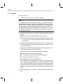
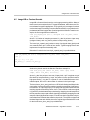
The Imaging Developer’s Kit (IDK) has been developed as a platform for development and demonstration of image/video processing applications on
TMS320C6000t DSPs. The IDK is based on the floating point C6711 DSP
may also be useful to developers using this platform to develop other algorithms for image, video, graphics processing.
How to Use This Manual
This document contains the following chapters:
- Chapter 1 – Introduction, provides information about the function and
process of the Imaging Developer’s Kit (IDK).
- Chapter 2 – Hardware Architecture, describes the IDK hardware archi-
tecture.
- Chapter 3 – Software Architecture – Applications Framework, de-
scribes the multiple software architecture levels of the IDK.
- Chapter 4 – Software Architecture – Algorithms Creation, describes
algorithm creation in the software architecture.
- Chapter 5 – Demonstration Scenarios, describes the demonstration
scenarios currently included in the IDK.
- Chapter 6 – C6000 DSP Image/Video Processing Applications, de-
scribes C6000 DSPs used in image/video processing applications.
- Chapter 7 – Testing and Compliance, describes how the initial versions
of the IDK meet the testing and compliance requirements.
- Appendix A – FPGA Interfaces, describes the FPGA interfaces to the
DSP EMIF through an asynchronous SRAM interface.
- Appendix B – Scaling Filters Algorithm, describes the scaling filters al-
gorithm.
Contents
iii
Related Documentation From Texas Instruments
- Appendix C – Using Image Data Manager, Demonstrates how to use the
DMA streaming routines to implement a sliding window.
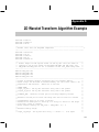
- Appendix D – 2D Wavelet Transform Algorithm Example, describes a
2D wavelet transform algorithm.
- Appendix E – eXpressDSP APIs for IDK Demonstrations, provides the
APIs pertinent to IDK demonstrations.
Related Documentation From Texas Instruments
The following references are provided for further information:
Documentation:
TMS320C6000 Imaging Developer’s Kit (IDK) Video Device Driver User’s
Guide (Literature number SPRU499)
TMS320C6000 Imaging Developer’s Kit (IDK) Programmer’s Guide
(Literature number SPRU495)
IDK Software Architecture Information:
For ImageLIB Information go to:
http://www.ti.com and navigate to the appropriate site.
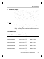
C6000 JPEG Information:
- TMS320C6000 JPEG Implementation Application Report (Literature
number SPRA704)
- Optimizing JPEG on the TMS320C6211 With 2-Level Cache Application
Report (Literature number SPRA705)
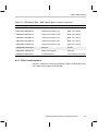
C6000 H.263 Information:
- H.263 Decoder: TMS320C6000 Implementation Application Report
(Literature number SPRA703)
- H.263 Encoder: TMS320C6000 Implementation Application Report
(Literature number SPRA721)
iv
Contents
Contents
1
Introduction . . . . . . . . . . . . . . . . . . . . . . . . . . . . . . . . . . . . . . . . . . . . . . . . . . . . . . . . . . . . . . . . . . . . . 1-1
Describes how the Imaging Developer’s Kit (IDK) has been developed as a platform for development and demonstration of image/video processing applications on TMS320C6000 DSPs.
1.1
1.2
2
Daughtercard Description . . . . . . . . . . . . . . . . . . . . . . . . . . . . . . . . . . . . . . . . . . . . . . . . . . . . 2-2
Video Capture . . . . . . . . . . . . . . . . . . . . . . . . . . . . . . . . . . . . . . . . . . . . . . . . . . . . . . . . . . . . . . 2-4
Video Display . . . . . . . . . . . . . . . . . . . . . . . . . . . . . . . . . . . . . . . . . . . . . . . . . . . . . . . . . . . . . . 2-9
Software Architecture – Applications Framework . . . . . . . . . . . . . . . . . . . . . . . . . . . . . . . . . . 3-1
Describes the multiple software architecture levels of the IDK.
3.1
3.2
3.3
3.4
3.5
3.6
4
1-2
1-3
1-3
1-4
Hardware Architecture . . . . . . . . . . . . . . . . . . . . . . . . . . . . . . . . . . . . . . . . . . . . . . . . . . . . . . . . . . . 2-1
Describes the IDK hardware architecture.
2.1
2.2
2.3
3
Overview . . . . . . . . . . . . . . . . . . . . . . . . . . . . . . . . . . . . . . . . . . . . . . . . . . . . . . . . . . . . . . . . . .
IDK as a Rapid Prototyping Platform . . . . . . . . . . . . . . . . . . . . . . . . . . . . . . . . . . . . . . . . . .
1.2.1 Rapid Prototyping Software Suite . . . . . . . . . . . . . . . . . . . . . . . . . . . . . . . . . . . . . .
1.2.2 Rapid Prototyping Hardware . . . . . . . . . . . . . . . . . . . . . . . . . . . . . . . . . . . . . . . . . .
Framework for Combining eXpressDSP-Compliant Algorithms . . . . . . . . . . . . . . . . . . . . 3-2
The IALG Interface . . . . . . . . . . . . . . . . . . . . . . . . . . . . . . . . . . . . . . . . . . . . . . . . . . . . . . . . . 3-6
Integrating an Algorithm into the Channel Manager . . . . . . . . . . . . . . . . . . . . . . . . . . . . . . 3-8
Channel Manager Object Types . . . . . . . . . . . . . . . . . . . . . . . . . . . . . . . . . . . . . . . . . . . . . . 3-9
Channel Manager Memory Management . . . . . . . . . . . . . . . . . . . . . . . . . . . . . . . . . . . . . 3-12
3.5.1 C6711 DSK Memory Architecture . . . . . . . . . . . . . . . . . . . . . . . . . . . . . . . . . . . . . 3-12
3.5.2 Data Memory Requirements of IDK Algorithms . . . . . . . . . . . . . . . . . . . . . . . . . 3-12
3.5.3 Internal and External Heaps . . . . . . . . . . . . . . . . . . . . . . . . . . . . . . . . . . . . . . . . . 3-13
3.5.4 Creation and Deletion of an Algorithm Instance . . . . . . . . . . . . . . . . . . . . . . . . . 3-14
3.5.5 Parent Instance Support . . . . . . . . . . . . . . . . . . . . . . . . . . . . . . . . . . . . . . . . . . . . . 3-15
Channel Manager API Functions . . . . . . . . . . . . . . . . . . . . . . . . . . . . . . . . . . . . . . . . . . . . 3-16
3.6.1 API Reference . . . . . . . . . . . . . . . . . . . . . . . . . . . . . . . . . . . . . . . . . . . . . . . . . . . . . 3-17
Software Architecture – Algorithms Creation . . . . . . . . . . . . . . . . . . . . . . . . . . . . . . . . . . . . . . 4-1
Describes algorithm creation in the software architecture.
4.1
4.2
4.3
4.4
4.5
4.6
Overview . . . . . . . . . . . . . . . . . . . . . . . . . . . . . . . . . . . . . . . . . . . . . . . . . . . . . . . . . . . . . . . . . . 4-2
eXpressDSP API Wrapper . . . . . . . . . . . . . . . . . . . . . . . . . . . . . . . . . . . . . . . . . . . . . . . . . . . 4-4
Algorithm . . . . . . . . . . . . . . . . . . . . . . . . . . . . . . . . . . . . . . . . . . . . . . . . . . . . . . . . . . . . . . . . . . 4-8
Image Processing Functions . . . . . . . . . . . . . . . . . . . . . . . . . . . . . . . . . . . . . . . . . . . . . . . . 4-10
ImageLIB or Custom Kernels . . . . . . . . . . . . . . . . . . . . . . . . . . . . . . . . . . . . . . . . . . . . . . . . 4-15
Image Data Manager . . . . . . . . . . . . . . . . . . . . . . . . . . . . . . . . . . . . . . . . . . . . . . . . . . . . . . . 4-19
v
Contents
5
Demonstration Scenarios . . . . . . . . . . . . . . . . . . . . . . . . . . . . . . . . . . . . . . . . . . . . . . . . . . . . . . . . 5-1
Describes the demonstration scenarios currently included in the IDK.
5.1
5.2
5.3
5.4
5.5
6
C6000 DSP Image/Video Processing Applications . . . . . . . . . . . . . . . . . . . . . . . . . . . . . . . . . . 6-1
Describes C6000 DSPs used in image/video processing applications.
6.1
6.2
6.3
6.4
vi
JPEG Loop-Back Demonstration . . . . . . . . . . . . . . . . . . . . . . . . . . . . . . . . . . . . . . . . . . . . . 5-2
5.1.1 Data I/O and User Input Specifics . . . . . . . . . . . . . . . . . . . . . . . . . . . . . . . . . . . . . . 5-2
5.1.2 Signal Processing Operations Sequence . . . . . . . . . . . . . . . . . . . . . . . . . . . . . . . 5-3
5.1.3 eXpressDSP APIs for JPEG Loop-Back Demonstration . . . . . . . . . . . . . . . . . . . 5-4
H.263 Multichannel Decoder Demonstration . . . . . . . . . . . . . . . . . . . . . . . . . . . . . . . . . . . . 5-5
5.2.1 Data I/O and User Input Specifics . . . . . . . . . . . . . . . . . . . . . . . . . . . . . . . . . . . . . . 5-5
5.2.2 Signal Processing Operations Sequence . . . . . . . . . . . . . . . . . . . . . . . . . . . . . . . 5-6
5.2.3 eXpressDSP APIs for H.263 Multichannel Decoder Demonstration . . . . . . . . . 5-7
Image Processing Demonstration . . . . . . . . . . . . . . . . . . . . . . . . . . . . . . . . . . . . . . . . . . . . . 5-8
5.3.1 Data I/O and User Input Specifics . . . . . . . . . . . . . . . . . . . . . . . . . . . . . . . . . . . . . . 5-9
5.3.2 Signal Processing Operations Sequence . . . . . . . . . . . . . . . . . . . . . . . . . . . . . . . 5-9
5.3.3 eXpressDSP APIs for Image Processing Demonstration . . . . . . . . . . . . . . . . . 5-10
H.263 Loop-Back Demonstration . . . . . . . . . . . . . . . . . . . . . . . . . . . . . . . . . . . . . . . . . . . . 5-11
5.4.1 Data I/O and User Input Specifics . . . . . . . . . . . . . . . . . . . . . . . . . . . . . . . . . . . . . 5-11
5.4.2 Signal Processing Operations Sequence . . . . . . . . . . . . . . . . . . . . . . . . . . . . . . 5-11
5.4.3 eXpressDSP APIs for H.263 Loop-Back Demonstration . . . . . . . . . . . . . . . . . 5-13
2D Wavelet Transform Demonstration . . . . . . . . . . . . . . . . . . . . . . . . . . . . . . . . . . . . . . . . 5-14
5.5.1 Data I/O and User Input Specifics . . . . . . . . . . . . . . . . . . . . . . . . . . . . . . . . . . . . . 5-14
5.5.2 Signal Processing Operations Sequence . . . . . . . . . . . . . . . . . . . . . . . . . . . . . . 5-14
5.5.3 eXpressDSP APIs for 2D Wavelet Transform Demonstration . . . . . . . . . . . . . 5-15
Overview . . . . . . . . . . . . . . . . . . . . . . . . . . . . . . . . . . . . . . . . . . . . . . . . . . . . . . . . . . . . . . . . . . 6-2
JPEG Encoder . . . . . . . . . . . . . . . . . . . . . . . . . . . . . . . . . . . . . . . . . . . . . . . . . . . . . . . . . . . . . 6-3
6.2.1 JPEG Encoder Algorithm Level Description . . . . . . . . . . . . . . . . . . . . . . . . . . . . . 6-3
6.2.2 JPEG Encoder Capabilities and Restrictions . . . . . . . . . . . . . . . . . . . . . . . . . . . . 6-5
6.2.3 JPEG Encoder API . . . . . . . . . . . . . . . . . . . . . . . . . . . . . . . . . . . . . . . . . . . . . . . . . . 6-6
6.2.4 JPEG Encoder Performance . . . . . . . . . . . . . . . . . . . . . . . . . . . . . . . . . . . . . . . . . . 6-7
6.2.5 Further Information on JPEG Encoder . . . . . . . . . . . . . . . . . . . . . . . . . . . . . . . . . . 6-8
JPEG Decoder . . . . . . . . . . . . . . . . . . . . . . . . . . . . . . . . . . . . . . . . . . . . . . . . . . . . . . . . . . . . . 6-9
6.3.1 JPEG Decoder Algorithm Level Description . . . . . . . . . . . . . . . . . . . . . . . . . . . . . 6-9
6.3.2 JPEG Decoder Capabilities and Restrictions . . . . . . . . . . . . . . . . . . . . . . . . . . . 6-11
6.3.3 JPEG Decoder API . . . . . . . . . . . . . . . . . . . . . . . . . . . . . . . . . . . . . . . . . . . . . . . . . 6-12
6.3.4 JPEG Decoder Performance . . . . . . . . . . . . . . . . . . . . . . . . . . . . . . . . . . . . . . . . . 6-14
6.3.5 Further Information on JPEG Decoder . . . . . . . . . . . . . . . . . . . . . . . . . . . . . . . . 6-14
H.263 Encoder . . . . . . . . . . . . . . . . . . . . . . . . . . . . . . . . . . . . . . . . . . . . . . . . . . . . . . . . . . . . 6-15
6.4.1 H.263 Encoder Algorithm Level Description . . . . . . . . . . . . . . . . . . . . . . . . . . . . 6-15
6.4.2 H.263 Encoder Capabilities and Restrictions . . . . . . . . . . . . . . . . . . . . . . . . . . . 6-17
6.4.3 H.263 Encoder API . . . . . . . . . . . . . . . . . . . . . . . . . . . . . . . . . . . . . . . . . . . . . . . . . 6-18
6.4.4 H.263 Encoder Performance . . . . . . . . . . . . . . . . . . . . . . . . . . . . . . . . . . . . . . . . . 6-20
6.4.5 Further Information on H.263 Encoder . . . . . . . . . . . . . . . . . . . . . . . . . . . . . . . . 6-20
Contents
6.5
6.6
H.263 Decoder . . . . . . . . . . . . . . . . . . . . . . . . . . . . . . . . . . . . . . . . . . . . . . . . . . . . . . . . . . . .
6.5.1 H.263 Decoder Algorithm Level Description . . . . . . . . . . . . . . . . . . . . . . . . . . . .
6.5.2 H.263 Decoder Capabilities and Restrictions . . . . . . . . . . . . . . . . . . . . . . . . . . .
6.5.3 H.263 Decoder API . . . . . . . . . . . . . . . . . . . . . . . . . . . . . . . . . . . . . . . . . . . . . . . . .
6.5.4 H.263 Decoder Performance . . . . . . . . . . . . . . . . . . . . . . . . . . . . . . . . . . . . . . . . .
6.5.5 Further Information on H.263 Decoder . . . . . . . . . . . . . . . . . . . . . . . . . . . . . . . .
ImageLIB – Library of Optimized Kernels . . . . . . . . . . . . . . . . . . . . . . . . . . . . . . . . . . . . .
6.6.1 Further Information on ImageLIB . . . . . . . . . . . . . . . . . . . . . . . . . . . . . . . . . . . . .
6-21
6-21
6-24
6-24
6-26
6-27
6-28
6-35
7
Testing and Compliance . . . . . . . . . . . . . . . . . . . . . . . . . . . . . . . . . . . . . . . . . . . . . . . . . . . . . . . . . 7-1
Describes how the initial versions of the IDK meet the testing and compliance requirements.
A
FPGA Interfaces . . . . . . . . . . . . . . . . . . . . . . . . . . . . . . . . . . . . . . . . . . . . . . . . . . . . . . . . . . . . . . . . . A-1
Describes the FPGA interfaces to the DSP EMIF through an asynchronous SRAM interface.
A.1
A.2
I2C Interface . . . . . . . . . . . . . . . . . . . . . . . . . . . . . . . . . . . . . . . . . . . . . . . . . . . . . . . . . . . . . . .
EMIF ASRAM Interface . . . . . . . . . . . . . . . . . . . . . . . . . . . . . . . . . . . . . . . . . . . . . . . . . . . . . .
A.2.1 CE Selection . . . . . . . . . . . . . . . . . . . . . . . . . . . . . . . . . . . . . . . . . . . . . . . . . . . . . . . .
A.2.2 IDK Memory Map . . . . . . . . . . . . . . . . . . . . . . . . . . . . . . . . . . . . . . . . . . . . . . . . . . . .
A.2.3 FPGA Control Registers . . . . . . . . . . . . . . . . . . . . . . . . . . . . . . . . . . . . . . . . . . . . . .
A-2
A-3
A-3
A-3
A-5
B
Scaling Filters Algorithm . . . . . . . . . . . . . . . . . . . . . . . . . . . . . . . . . . . . . . . . . . . . . . . . . . . . . . . . . B-1
Describes the scaling filters algorithm.
C
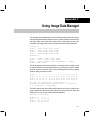
Using Image Data Manager . . . . . . . . . . . . . . . . . . . . . . . . . . . . . . . . . . . . . . . . . . . . . . . . . . . . . . . C-1
Demonstrates how to use the DMA streaming routines to implement a sliding window.
D
2D Wavelet Transform Algorithm Example . . . . . . . . . . . . . . . . . . . . . . . . . . . . . . . . . . . . . . . . . D-1
Describes a 2D wavelet transform algorithm.
E
eXpressDSP APIs for IDK Demonstrations . . . . . . . . . . . . . . . . . . . . . . . . . . . . . . . . . . . . . . . . E-1
Provides the APIs pertinent to IDK demonstrations.
E.1
E.2
E.3
E.4
E.5
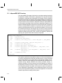
eXpressDSP API Overview . . . . . . . . . . . . . . . . . . . . . . . . . . . . . . . . . . . . . . . . . . . . . . . . . .
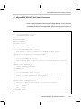
eXpressDSP API for Pre-Scale Filter . . . . . . . . . . . . . . . . . . . . . . . . . . . . . . . . . . . . . . . . . .
eXpressDSP API for Color Space Conversion . . . . . . . . . . . . . . . . . . . . . . . . . . . . . . . . . .
eXpressDSP API for Image Processing Functions . . . . . . . . . . . . . . . . . . . . . . . . . . . . .
eXpressDSP API for Wavelet Transform . . . . . . . . . . . . . . . . . . . . . . . . . . . . . . . . . . . . . . .
Contents
E-2
E-3
E-5
E-7
E-9
vii
Figures
Figures
2–1
2–2
2–3
2–4
2–5
2–6
2–7
3–1
3–2
3–3
3–4
3–5
4–1
4–2
5–1
5–2
5–3
5–4
5–5
5–6
5–7
6–1
6–2
6–3
6–4
6–5
6–6
6–7
6–8
6–9
6–10
6–11
A–1
viii
IDK daughtercard Block Diagram . . . . . . . . . . . . . . . . . . . . . . . . . . . . . . . . . . . . . . . . . . . . . . . . 2-3
NTSC Capture (1 of 3 frames shown) . . . . . . . . . . . . . . . . . . . . . . . . . . . . . . . . . . . . . . . . . . . . 2-5
Capture Buffer Management . . . . . . . . . . . . . . . . . . . . . . . . . . . . . . . . . . . . . . . . . . . . . . . . . . . . 2-7
Display Event Generation . . . . . . . . . . . . . . . . . . . . . . . . . . . . . . . . . . . . . . . . . . . . . . . . . . . . . 2-11
Display Interrupt Generation . . . . . . . . . . . . . . . . . . . . . . . . . . . . . . . . . . . . . . . . . . . . . . . . . . . 2-12
GRAY8 Display Buffer Format . . . . . . . . . . . . . . . . . . . . . . . . . . . . . . . . . . . . . . . . . . . . . . . . . 2-13
RGB16 Display Buffer Format . . . . . . . . . . . . . . . . . . . . . . . . . . . . . . . . . . . . . . . . . . . . . . . . . 2-13
IDK Demo Block Diagram . . . . . . . . . . . . . . . . . . . . . . . . . . . . . . . . . . . . . . . . . . . . . . . . . . . . . . 3-3
Channel Task Layouts for JPEG Loop-Back Demo and Image Processing Demo . . . . . . 3-4
JPEG Loop-Back Channel . . . . . . . . . . . . . . . . . . . . . . . . . . . . . . . . . . . . . . . . . . . . . . . . . . . . 3-10
JPEG Loop-Back Demo Channels and I/O Buffers . . . . . . . . . . . . . . . . . . . . . . . . . . . . . . . . 3-11
Split Cache/SRAM Mode with QDMA Data Transfer . . . . . . . . . . . . . . . . . . . . . . . . . . . . . . 3-12
Software Architecture for ImageLIB Functions-Based Standard Algorithms . . . . . . . . . . . 4-2
2D Wavelet Transform . . . . . . . . . . . . . . . . . . . . . . . . . . . . . . . . . . . . . . . . . . . . . . . . . . . . . . . . . 4-3
JPEG Loop-Back Demonstration . . . . . . . . . . . . . . . . . . . . . . . . . . . . . . . . . . . . . . . . . . . . . . . . 5-2
Multichannel H.263 Decode Demonstration . . . . . . . . . . . . . . . . . . . . . . . . . . . . . . . . . . . . . . . 5-5
Image Processing Demonstration . . . . . . . . . . . . . . . . . . . . . . . . . . . . . . . . . . . . . . . . . . . . . . . 5-8
Image Processing Demonstration Display . . . . . . . . . . . . . . . . . . . . . . . . . . . . . . . . . . . . . . . . 5-8
H.263 Loop-Back Demonstration . . . . . . . . . . . . . . . . . . . . . . . . . . . . . . . . . . . . . . . . . . . . . . . 5-11
2D Wavelet Transform Demonstration . . . . . . . . . . . . . . . . . . . . . . . . . . . . . . . . . . . . . . . . . . 5-14
2D Wavelet Transform Components . . . . . . . . . . . . . . . . . . . . . . . . . . . . . . . . . . . . . . . . . . . . 5-14
JPEG Encoder . . . . . . . . . . . . . . . . . . . . . . . . . . . . . . . . . . . . . . . . . . . . . . . . . . . . . . . . . . . . . . . . 6-3
Raster Scanned Image Data . . . . . . . . . . . . . . . . . . . . . . . . . . . . . . . . . . . . . . . . . . . . . . . . . . . . 6-3
Reformatted Image Data . . . . . . . . . . . . . . . . . . . . . . . . . . . . . . . . . . . . . . . . . . . . . . . . . . . . . . . 6-3
Zig-Zag Reordering of Transformed Coefficients (Input and Output) . . . . . . . . . . . . . . . . . . 6-5
JPEG Decoder . . . . . . . . . . . . . . . . . . . . . . . . . . . . . . . . . . . . . . . . . . . . . . . . . . . . . . . . . . . . . . . 6-9
Decoded Image Data Before Reformat . . . . . . . . . . . . . . . . . . . . . . . . . . . . . . . . . . . . . . . . . . 6-11
Reformatted Image Data in Raster Scan Format . . . . . . . . . . . . . . . . . . . . . . . . . . . . . . . . . 6-11
H.263 Encoder Overview . . . . . . . . . . . . . . . . . . . . . . . . . . . . . . . . . . . . . . . . . . . . . . . . . . . . . . 6-16
h263EncMB Overview . . . . . . . . . . . . . . . . . . . . . . . . . . . . . . . . . . . . . . . . . . . . . . . . . . . . . . . . 6-17
H.263 Decoder Overview . . . . . . . . . . . . . . . . . . . . . . . . . . . . . . . . . . . . . . . . . . . . . . . . . . . . . 6-22
h263DecMB Overview . . . . . . . . . . . . . . . . . . . . . . . . . . . . . . . . . . . . . . . . . . . . . . . . . . . . . . . . 6-23
FPGA Control Registers . . . . . . . . . . . . . . . . . . . . . . . . . . . . . . . . . . . . . . . . . . . . . . . . . . . . . . . A-6
Tables
Tables
2–1
2–2
2–3
2–4
3–1
5–1
6–1
6–2
6–3
6–4
6–5
6–6
A–1
A–2
A–3
A–4
Video Capture Memory Requirements . . . . . . . . . . . . . . . . . . . . . . . . . . . . . . . . . . . . . . . . . . . 2-4
Capture Events . . . . . . . . . . . . . . . . . . . . . . . . . . . . . . . . . . . . . . . . . . . . . . . . . . . . . . . . . . . . . . . 2-8
Display Events . . . . . . . . . . . . . . . . . . . . . . . . . . . . . . . . . . . . . . . . . . . . . . . . . . . . . . . . . . . . . . . . 2-9
Display Modes . . . . . . . . . . . . . . . . . . . . . . . . . . . . . . . . . . . . . . . . . . . . . . . . . . . . . . . . . . . . . . . 2-12
C6211/C6711 L2 Operation Modes for IDK Demos . . . . . . . . . . . . . . . . . . . . . . . . . . . . . . . 3-13
DSK Board Memory Budget Allocations for Multichannel H.263 Decode . . . . . . . . . . . . . . 5-6
JPEG Encoder Performance . . . . . . . . . . . . . . . . . . . . . . . . . . . . . . . . . . . . . . . . . . . . . . . . . . . . 6-8
JPEG Decoder Performance . . . . . . . . . . . . . . . . . . . . . . . . . . . . . . . . . . . . . . . . . . . . . . . . . . 6-14
H.263 Encoder Performance . . . . . . . . . . . . . . . . . . . . . . . . . . . . . . . . . . . . . . . . . . . . . . . . . . 6-20
H.263 Decoder Performance . . . . . . . . . . . . . . . . . . . . . . . . . . . . . . . . . . . . . . . . . . . . . . . . . . 6-27
ImageLIB Kernels . . . . . . . . . . . . . . . . . . . . . . . . . . . . . . . . . . . . . . . . . . . . . . . . . . . . . . . . . . . . 6-28
ImageLIB Kernels Performance . . . . . . . . . . . . . . . . . . . . . . . . . . . . . . . . . . . . . . . . . . . . . . . 6-32
I2C Base Address . . . . . . . . . . . . . . . . . . . . . . . . . . . . . . . . . . . . . . . . . . . . . . . . . . . . . . . . . . . . . A-2
IDK Memory Map – 2MB Capture Memory Option . . . . . . . . . . . . . . . . . . . . . . . . . . . . . . . . A-3
IDK Memory Map – 8MB Capture Memory Option . . . . . . . . . . . . . . . . . . . . . . . . . . . . . . . . A-4
IDK FPGA Control Register Bit Descriptions . . . . . . . . . . . . . . . . . . . . . . . . . . . . . . . . . . . . . A-7
Contents
ix
Chapter 1
Introduction
The Imaging Developer’s Kit (IDK) has been developed as a platform for development and demonstration of image/video processing applications on
TMS320C6000t DSPs.
Topic
Page
1.1
Overview . . . . . . . . . . . . . . . . . . . . . . . . . . . . . . . . . . . . . . . . . . . . . . . . . . . . . 1-2
1.2
IDK as a Rapid Prototyping Platform . . . . . . . . . . . . . . . . . . . . . . . . . . . . 1-3
1-1
Overview
1.1 Overview
The IDK consists of:
- TMS320C6711 DSK board with 16Mbytes SDRAM
Note:
The image/video processing algorithms included in the IDK are fixed point
implementations suitable for operation on fixed point DSPs such as the
TMS320C6211. The IDK is based on the TMS320C6711 floating point DSK
board only because TI is standardizing DSK boards on the C6711 DSP. The
fact that the IDK is based on the floating point C6711 DSP may also be useful
to developers using this platform to develop other algorithms for image, video, graphics processing.
- Imaging Daughtercard for video capture, display, and data conversion
support
J
Input signals are limited to NTSC/PAL composite video.
J
Display is limited to 640x480 or 800x600 pixels RGB Computer Monitor, driven by drivers for 8 bits/pixel (gray scale), or 16 bits/pixel (565
format RGB).
- Software toolkit consisting of Code Composer Studiot v2 on the IDK soft-
ware CD, which also includes a chip support library (CSL) used for the video drivers and demos.
- Demonstration software showcasing C6000 DSP capabilities across a
range of image/video processing applications:
J
JPEG loop-back (encoder and decoder) demonstration
J
Multichannel H.263 decoder demonstration
J
H.263 loop-back (encoder and decoder) demonstration
J
2D Wavelet transform demonstration
J
Image processing functions demonstration
The JPEG loop-back, H.263 decoder, and H.263 loop-back demonstrations are built using licensable libraries. The other demonstrations are built
using ImageLIB, a navailable library of optimized image/video processing
kernels (see section 6.6 for details on ImageLIB). It is easy with the IDK
platform to run these libraries in real-time and make algorithm adjustments.
- Device driver software for video capture, display, and demonstrations sup-
port
1-2
IDK as a Rapid Prototyping Platform
1.2 IDK as a Rapid Prototyping Platform
In addition to showcasing the demonstrations listed previously, the IDK also
serves as a rapid prototyping platform for the development of image and video
processing algorithms. Using the software and hardware components provided in the IDK, developers can quickly move from algorithm concepts development to high performance working implementations on TMS320C6000
DSP board, with live video input and output to evaluate their algorithms. This
rapid prototyping ability is based on the following developments included in the
IDK.
1.2.1
Rapid Prototyping Software Suite
The Rapid Prototyping Software Suite consists of a software package that includes ImageLIB, Chip Support Library (CSL), and Image Data Manager:
ImageLIB: This is an optimized Image/Video Processing Functions Library for
C programmers on TMS320C6000 devices. It includes many C-callable, assembly-optimized, general-purpose image/video processing routines. These
routines are typically used in computationally intensive real-time applications
where optimal execution speed is critical. ImageLIB offers the following advantages to software developers:
- By using the routines provided in ImageLIB, an application can achieve
execution speeds that are considerably faster than equivalent code written in standard ANSI C language.
- By providing ready-to-use DSP functions, ImageLIB can significantly
shorten image/video processing application development time.
ImageLIB software and associated documentation is available by accessing:
http://www.ti.com and navigating to the appropriate site.
Chip Support Library (CSL): CSL is a set of Application Programming Interfaces (APIs) used to configure and control all on-chip peripherals. It is intended
to make software development easier in making algorithms operational in a
system. The goal of this library is ease of peripheral use, some level of compatibility between devices, shortened development time, code portability, some
standardization, and hardware abstraction. CSL offers the following advantages to software developers:
- Enables development of DSP application code without having to physical-
ly program the registers of peripherals. This helps to make the programming task easier, quicker, and there is also less potential for mistakes.
- The availability of CSL for all C6000 devices allows an application to be
developed once and run on any member of the TMS320C6000 DSP
family.
Introduction
1-3
IDK as a Rapid Prototyping Platform
- The ability to develop new libraries that use CSL as their foundation to al-
low for easy data transferred. An example of this is the Image Data Manager (described below) that uses CSL to abstract the details of double buffered DMAs.
CSL software and associated documentation is available by accessing:
http://www.ti.com and navigating to the appropriate site.
Image Data Manager: Image Data Manager is a set of library routines that offer abstraction for double buffering of DMA requests, to efficiently move data
in the background during processing. They have been developed to help remove the burden from the user of having to perform pointer updates and managing buffers in the code. Image Data Manager uses CSL calls to move data
between external and internal memory during the course of processing. Image
Data Manager offers the following advantages to software developers:
- The ability to separate and compartmentalize data transfers from the algo-
rithm, leading to software that is easy to understand and simple to maintain
- The ability to re-use the data transfer routines where applicable
1.2.2
Rapid Prototyping Hardware
The IDK hardware consists of a C6711 DSK with 16MB SDRAM, and a daughter-card that provides the following capabilities:
- Video Capture of NTSC/PAL signals (composite video)
- Display of RGB signals, 640x480 or 800x600 resolution, 16-bits per pixel
(565 format)
- Video data formatting by an on-board FPGA to convert captured inter-
leaved 4:2:2 data to separate Y, Cr, Cb components that may be sent to
the DSP for processing
- Video capture and display drivers software written using DSP/BIOS and
CSL
This enables users to quickly set up a development environment that includes
video input and output capability.
1-4
Chapter 2
Hardware Architecture
The IDK hardware consists of a C6711 DSK with 16MB SDRAM, and a daughtercard that provides video capture, display, and formatting capabilities.
Topic
Page
2.1
Daughtercard Description . . . . . . . . . . . . . . . . . . . . . . . . . . . . . . . . . . . . . 2-2
2.2
Video Capture . . . . . . . . . . . . . . . . . . . . . . . . . . . . . . . . . . . . . . . . . . . . . . . . 2-4
2.3
Video Display . . . . . . . . . . . . . . . . . . . . . . . . . . . . . . . . . . . . . . . . . . . . . . . . . 2-9
2-1
Daughtercard Description
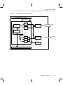
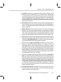
2.1 Daughtercard Description
The daughtercard (Figure 2–1) includes:
- NTSC/PAL digital video decoder IC (TI TVP5022)
- Video Palette IC (TI TVP3026C)
- Xilinx field programmable gate array (FPGA) that includes the following
functions: card controller, FIFO buffer manager, front/back end interfaces.
Details of the interfaces served by the FPGA are provided in Appendix A.
- 16-Mbit SDRAM (capture frame memory), with option to support 64-Mbit
devices
The daughtercard provides the ability for the following types of video capture
and display:
- Input video signal capture is limited to a single NTSC/PAL signal
- Input signal should of composite video format
- Display output may be in the form of an 8-bit gray scale or a 16-bit RGB
(565) signal
The daughtercard hardware includes the following:
- One set of TMS320C6000 daughtercard connectors (male, solder side)
- Female RCA connector for composite video input (NTSC/PAL)
- Female 15-pin VGA connector for RGB monitor output
2-2
Daughtercard Description
Figure 2–1. IDK daughtercard Block Diagram
Peripheral daughtercard connector
Events (TINPn, EINTn)
FPGA
Video
CTL
Display line
FIFO
32
TVP3026
RGB
out
TVP5022
Composite
in
CTL
regs
Write
enable
EMIF logic
SDRAM
CTL
Y
8
Cr
Cb
Line FIFOs
16
Display line
FIFO
DSP EMIF interface
Peripheral daughtercard connector
Hardware Architecture
2-3
Video Capture
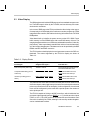
2.2 Video Capture
The IDK daughtercard includes one video input port for NTSC/PAL video. The
NTSC/PAL input consists of an industry standard RCA jack for composite video input. The input is routed to the TVP5022 video decoder, and may be configured for square-pixel or ITU standard resolutions. The TVP5022 performs digitization and minimal filtering of the video inputs. All video input data is digitized
in the 4:2:2 format, to produce a standard YCrCb pixel stream. Since most
DSP algorithms operate on input data as separate Y, Cr, and Cb blocks, the
FPGA interface performs separation of the digital stream before writing it to the
capture frame buffer. Captured data is stored as two separate fields, in three
separate blocks in the frame buffer.
Data is expected from the TVP5022 in the Cr0-Y0, Cb0-Y1, Cr2-Y2,
Cb2-Y3, … format. The FPGA internally adjusts the data stream for endian,
and stores it into the capture frame memory as shown in Figure 2–2. The
FPGA manages a capture frame buffer in an on-board SDRAM memory bank.
SDRAM was chosen due to its low cost for the required memory bank size,
however, the DSP interface to this buffer is of the ASRAM type. The FPGA performs this translation autonomously. It is noted that the capture frame memory
is read only to the DSP interface. Any writes attempted to the frame memory
by the DSP are discarded.
The FPGA SDRAM controller supports both 2MB and 8MB configurations of
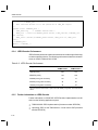
SDRAM and is controllable via software. Table 2–1 outlines the capture formats vs memory requirements.
Table 2–1. Video Capture Memory Requirements
Format
Required Memory
NTSC, square pixel
2MB
PAL, square pixel
8MB
NTSC, ITU601
2MB
PAL, ITU601
8MB
Note:
The TVP5022 chipset and FPGA support sampling of all versions of the PAL
standard, though stuffing options of the TVP5022 crystal may be required.
2-4
Video Capture
Figure 2–2. NTSC Capture (1 of 3 frames shown)
Field 0
Y Buffer
Cr Buffer
Cb Buffer
Field 1
Y Buffer
Cr Buffer
Cb Buffer
Little Endian
Big Endian
first pixel captured
32 bits
Y Buffer
32 bits
Y3
Y2
Y1
Y0
Word
000
Y7
Y6
Y5
Y4
Y11
Y10
Y9
Y15
Y14
Y13
Word
000
Y0
Y1
Y2
Y3
001
001
Y4
Y5
Y6
Y7
Y8
010
010
Y8
Y9
Y10
Y11
Y12
011
011
Y12
Y13
Y14
Y15
Cr4
Cr6
...
...
first pixel captured
Cr Buffer
Cr6
Cr4
Cr2
Cr0
Cr0
Cr2
Cr14 Cr12 Cr10
Cr8
Cr8
Cr10 Cr12 Cr14
...
...
first pixel captured
Cb Buffer
Cb6
Cb4
Cb2
Cb14 Cb12 Cb10
...
Cb0
Cb0
Cb2
Cb4
Cb6
Cb8
Cb8
Cb10 Cb12 Cb14
...
Hardware Architecture
2-5
Video Capture
Read accesses to the frame memory are throttled as appropriate using the
DSP EMIF ARDY signal. Since the SDRAM memory is faster than the ASRAM
interface, this is generally only necessary at the beginning of a burst of reads,
and possibly when refreshes of the SDRAM bank are required. The FPGA includes a small read FIFO to minimize the effect of this. It should be noted however, that the frame memory management is most efficient when accessed linearly. It is suggested that the application software access the memory in a linear fashion, to minimize SDRAM page misses which slow the memory transactions. The ARDY signal is also asserted when bank conflicts occur, resulting
from arbitration effects with the capture line FIFOs. The effect is minimized by
the existence of the FIFOs, plus a priority scheme implemented in the FPGA
controller.
All video input timing is provided by the TVP5022. This includes a vertical synchronization pulse, plus a composite blanking signal which indicates the presence of active data on the pixel bus. A pixel clock is also provided, which is
used by the FPGA to latch data into the aforementioned line FIFOs. Data is
routed to the FPGA over an 8-bit video input port. Data may be captured in either the square pixel (640x480 or 768x576) or ITU (720x480 or 720x576) format. The format is determined via a control register bit in the TVP5022, which
must be programmed to denote line length divisibility by 64 or 72 (all formats
fit into one of these two categories). The setting of the input mode, as well as
complete configuration of the TVP5022, is provided via an I2C interface. A
complete list of the addressable registers and their functions in the TVP5022
is available by accessing:
http://www.ti.com and navigating to the appropriate site.
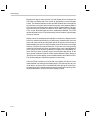
Captured data is stored as two separate fields (odd and even fields), in three
separate blocks (Y, Cr, Cb) in the frame buffer memory on the daughtercard.
Note that the memory locations of the fields, as well as the blocks within the
fields, are not necessarily contiguous. Up to three frames of captured data may
be stored in the daughtercard memory. At any given time, the FPGA controls
two of the buffers to which it writes captured video data in a ping-pong fashion.
The application has access to the third buffer, which typically has the most recently captured data. If the application falls behind in processing, the two buffers that the FPGA controls can be toggled and the application simply runs at
a processing rate less than the captured 30 frames/sec. If the application can
maintain the full processing rate, the buffers are physically walked through by
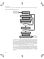
both the FPGA and the application in a circular fashion. See Figure 2–3 for an
explanation of the capture buffer management.
2-6
Video Capture
Figure 2–3. Capture Buffer Management
Application
owns
FPGA owns
Y
Y
Y
Cr
Cr
Cr
Cb
Cb
Cb
Buffer A
t2 input
Buffer B
t1 input
Buffer C
t0 input
on VSYNC falling;
if FLIP–PAGE
requested
Application
owns
FPGA owns
Y
Y
Y
Cr
Cr
Cr
Cb
Cb
Cb
Buffer A
t2 input
Buffer C
t3 input
Buffer B
t1 input
else
Application
owns
FPGA owns
Y
Y
Y
Cr
Cr
Cr
Cb
Cb
Cb
Buffer A
t2 input
Buffer B
t3 input
Buffer C
t0 input
The FPGA directly controls all the capture data management, without any DSP
resource (specifically, a DMA channel). The FPGA provides a capture frame
interrupt to the DSP, which is used to inform the driver that a new frame is available for processing. The capture event may be mapped to one of the DSP
events as shown in Table 2–2.
Hardware Architecture
2-7
Video Capture
Table 2–2. Capture Events
DSP Event
Mapped to System Event …
Intended Use …
EINTn (n = 4–7)
Vertical sync falling (end of captured frame)
Interrupt to CPU driver
Any DSP event line not tied to a capture (or display) event is tri-stated, such
that it may be used by another daughtercard or motherboard interface.
To maintain this buffer scheme, it is necessary for the IDK driver software to
inform the FPGA when the application has completed use of its buffer, and that
it may be returned to the pool of capture buffers which the FPGA owns. This
event is generically referred to as a ‘flip page’ function. Once the flip page request has occurred (via write to an FPGA control register bit), the IDK driver
can read another FPGA register to extract the buffer number which may be returned to the application. Because of the three-buffer architecture, this can occur immediately after the flip page request has been posted, even though the
capture stream may not be at a point where this could occur had a two-buffer
scheme been used. The FPGA performs the page flip during the capture vertical blank interval. Special detection logic is included to avoid boundary conditions, which are specifically the end and start of vertical synchronization.
Note the following, specific to IDK demonstrations:
- While the daughtercard provides support for little endian as well as big en-
dian data, all data is assumed to be little endian for the IDK.
- Some of the IDK demonstrations make use of only one of the odd or even
fields of video data. Since the daughtercard assigns odd and even fields
to separate memory locations, this is comprehended by only addressing
one of the fields for data read for DSP processing.
- While capture is limited to 4:2:2 format, some of the IDK demonstrations
require 4:2:0 data. 4:2:2 to 4:2:0 conversion is achieved by reading every
other line of captured C data for DSP processing. While this is not an entirely accurate way to convert 4:2:2 data to 4:2:0 from a theoretical standpoint, it has been found to be adequate for simple demonstrations.
- While capture resolution is limited to 640x480 or 720x480 pixels, some of
the IDK demonstrations require other resolutions (e.g., 320x240). Such a
resolution conversion is achieved by using Scaling Filters described in
Appendix B.
- Capture drivers supporting the video capture modes discussed here, are
included in the IDK. The drivers are written using DSP/BIOS and CSL.
Refer to the TMS320C6000 Imaging Developer’s Kit (IDK) Video Device
Driver’s User’s Guide (Literature number SPRU499) for further details.
2-8
Video Display
2.3 Video Display
The IDK daughtercard includes RGB output port for a standard computer monitor. The RGB output is driven by the TVP3026, and can drive any of the standard monitor resolutions.
In the case of RGB output the FPGA provides the video timing to the output.
Consequently, the DSP display driver software must also program the FPGA
integrated video controller, which drives the timing information to the TVP3026
RGB palette.
Video data is built up in buffers in system memory on the C6711 DSK. Frame
buffer memory is of the SDRAM type, with a read CAS latency of three. The
imaging daughtercard does not include any addressable amount of video display memory. Video output data is transferred in real-time from the frame buffer to the imaging daughtercard. This data service can be provided by the DSP
EDMA controller and EMIF resources.
The FPGA monitors the display device and generates events to the DSP motherboard. The events supported by the FPGA for display are shown in
Table 2–3.
Table 2–3. Display Events
Event/Signal
May be Mapped to
daughtercard Signal …
Pixel clock (active pixels only)
TOUT0 or TOUT1
Timer period set to pixels per line,
TINT drives DMA line event
Composite blank falling (end of
active line)
EINT7, EINT6, EINT5, EINT4
EINTn drives DMA line event;
Vertical sync falling (end of
frame)
EINT7, EINT6, EINT5, EINT4
Intended Use …
EINTn drives CPU interrupt
EINTn drives DMA frame event;
EINTn drives CPU interrupt
The preferred use of the above events is that the pixel clock be routed to one
of the timer inputs, and a single interrupt is used on the vertical synchronization
pulse to synchronize the DSP to the display. In this configuration, the selected
timer must be configured in pulse mode with a period equal to the number of
active pixels per line.
The FPGA is capable of driving to all DSP event lines, which include the four
processor edge-triggered interrupts (EINTn, n = 4–7) and the two timer inputs
(TINPn, n= 0 or 1). Any DSP event line not selected for one of the above event
sources is tri-stated by the FPGA, allowing it to be used by another daughtercard or motherboard interface.
Hardware Architecture
2-9
Video Display
Based on the above event selection, the IDK Display Driver configures the
DSP DMA (or EDMA) and timer module (if appropriate) to service display
events. The intended operation is that one DMA channel will be dedicated to
servicing line events (once per horizontal sync pulse), and a separate DMA or
CPU event per vertical sync pulse will be used for synchronization. The horizontal event forces the DMA to transfer a line of data to the FPGA display
FIFO, via the aforementioned read of the motherboard SDRAM. The FPGA
latches this data into the FIFO autonomously, which feeds the output display
devices in real time.
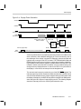
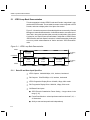
Display events are scheduled such that data is ready for the display devices
before it is needed. Specifically, this is achieved by scheduling the first event
at the end of the vertical synchronization period. At this point, several lines of
blanked display (for which no data is needed) must still be timed, so the DMA
has time to perform the required accesses. In the case of an interrupt being
used for the horizontal line events, generation of this event is straightforward.
In the case of a timer however, generation is slightly more complicated, because the FPGA does not always source the horizontal video timing. In this
case, special hardware inside the FPGA inserts additional TINPn pulses to
‘fake’ a first line of video display, to force a DMA of data to the FPGA line FIFO.
The following diagram outlines the operation in both cases.
Since the FPGA is always one line ahead of the display, the last line event
reads data that is off the end of the display buffer. This does not have any adverse effects, as the line FIFO is automatically reset during the vertical synchronization period. The data read is discarded, and the first line event generation described above re-synchronizes the display properly.
2-10
Video Display
Figure 2–4. Display Event Generation
VSYNC
CBLNK
EINTn
(if enabled)
TINPn
(if enabled)
FPGA ‘fakes’ first lines
worth of pixel clocks on
TINPn if enabled
=640 or 720
DSP
DMA
DSP
timer
last line (bogus data)
DMA
activity
first line
second line
third line
FIFO held in reset, discards last data
Vertical synchronization is not explicitly necessary, however it is added for the
ease of software, and to facilitate debugging in a clean environment. One of
the challenges of the design is support for debugging, wherein the DMA will
typically keep running but the CPU is halted. The TMS320C6000 DMA and
EDMA controllers both have provisions to support auto-reloading (called linking in EDMA) of parameters to maintain synchronization while the DSP core
is halted. However, when the DSP is restarted, it may be restarted at any point
during an actively displayed frame. In order for the DSP to re-synchronize to
the display, it must receive an interrupt from the daughtercard.
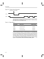
The vertical event interrupt is provided via one of the DSP EINTn signals. The
interrupt signal may also be routed to the DMA controller within the DSP, which
can be used as an added security measure against losing synchronization with
the display. Alternatively, the DSP ISR may wish to reprogram the DMA parameters during the ISR, as part of a page flipping routine. The following diagram
shows the interrupt point for the vertical synchronization event.
Hardware Architecture
2-11
Video Display
Figure 2–5. Display Interrupt Generation
Interrput to CPU (and/or DMA)
VSYNC
CBLNK
Video display data written to the FPGA FIFO is extracted from the FIFO by the
IDK display device, the RGB palette (TVP3026). Table 2–4 outlines the support matrix for the various display modes.
Table 2–4. Display Modes
Display Mode
Data Format
Output Selected
GRAY8
8-bit grayscale
TVP3026
RGB8
VGA (256 colors)
TVP3026
RGB16
5-6-5 or x-5-5-5
TVP3026
RGB32
True color (24-bit)
TVP3026
From the modes listed in Table 2–4, the IDK initially uses a 16-bit RGB display
mode, and an 8-bit gray-scale display mode is utilized for demonstrations with
gray-scale output. Display drivers supporting these video display modes are
included in the IDK. The drivers are written using DSP/BIOS and CSL. Refer
to the TMS320C6000 Imaging Developer’s Kit (IDK) Video Device Driver’s
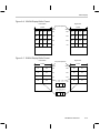
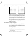
User’s Guide (Literature number SPRU499) for details. Figure 2–6 and
Figure 2–7 show the frame buffer format for these display options.
2-12
Video Display
Figure 2–6. GRAY8 Display Buffer Format
Little Endian
Big Endian
first pixel captured
32 bits
32 bits
P3
P2
P1
P0
Word
000
P7
P6
P5
P4
P11
P10
P9
P15
P14
P13
Word
000
P0
P1
P2
P3
001
001
P4
P5
P6
P7
P8
010
010
P8
P9
P10
P11
P12
011
011
P12
P13
P14
P15
...
...
Figure 2–7. RGB16 Display Buffer Format
Little Endian
Big Endian
first pixel captured
32 bits
32 bits
P1
P0
Word
000
P3
P2
P5
P7
Word
000
P0
P1
001
001
P2
P3
P4
010
010
P4
P5
P6
011
011
P6
P7
31 27 26 21 20 16
15 11 10 5 4 0
R
G
...
B
...
or
31 30 26 25 2120 16
15 14 10 9 5 4 0
R
G
B
Hardware Architecture
2-13
Chapter 3
Software Architecture –
Applications Framework
The IDK has multiple software architecture levels. At the highest level, the IDK
framework provides a way to pipeline eXpressDSP-compliant algorithms easily. Some of the standard algorithms used are exposed to the user only at the
algorithm level such as the JPEG encoder, JPEG decoder, H.263 decoder,
H.263 encoder.
These algorithms are made available in source code form only under license.
The framework software provides a means for building demonstrations using
combinations of such applications level code – an example is the JPEG LoopBack demonstration that combines Pre-Scale Filter, JPEG Encode, JPEG Decode, and Color Space Conversion.
Other standard algorithms for simpler image processing functions have been
built using a common layering approach combining ImageLIB kernels with the
Image Data Manager. There are several different buffering schemes supported by the Image Data Manager. Image Processing functions that require
the same buffering can easily be implemented using a common wrapper structure.
Topic
Page
3.1
Framework for Combining eXpressDSP-Compliant Algorithms . . . 3-2
3.2
The IALG Interface . . . . . . . . . . . . . . . . . . . . . . . . . . . . . . . . . . . . . . . . . . . . 3-6
3.3
Integrating an Algorithm into the Channel Manager . . . . . . . . . . . . . . 3-8
3.4
Channel Manager Object Types . . . . . . . . . . . . . . . . . . . . . . . . . . . . . . . . 3-9
3.5
Channel Manager Memory Management . . . . . . . . . . . . . . . . . . . . . . . 3-12
3.6
Channel Manager API Functions . . . . . . . . . . . . . . . . . . . . . . . . . . . . . . 3-16
3-1
Framework for Combining eXpressDSP-Compliant Algorithms
3.1 Framework for Combining eXpressDSP-Compliant Algorithms
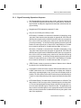
Each of the IDK demo applications consists of two separate parts, the Host
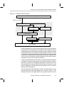
GUI and the target Executable. Figure 3-1 shows the system block diagram
of all the imaging demonstrations that have more than one processing channel. For the wavelet transform demo, the I/O task and the channel task are
merged into one task because there is only one processing channel.
Target Executables are built upon DSP/BIOS kernel and the C6211/C6711
Chip Support Library (CSL). The tasks shown in Figure 3–1 are literally DSP/
BIOS tasks. There are three types of tasks in the IDK Demos.
- The Message-Handling Task detects a command sent from the Host
GUI, parses the command and dispatches it to appropriate tasks for actions. Examples are commands to change frame-rate for each channel
task, and to suspend or resume a channel task.
- The I/O Task calls capture and display drivers to get input and output buff-
ers for all channel tasks. It signals each channel task for the readiness of
its I/O buffers and waits for completion signals from channel tasks before
releasing input and output buffers back to drivers. Synchronization among
tasks is achieved by using the DSP/BIOS semaphore objects. In some
cases such as in the JPEG Loop-Back and the Image Processing Demos,
pre-processing is also performed in the I/O task.
- Each Channel Task consists of an instance of the channel object, created
by calling CM_Open() and represented by the handle returned from that
call. Each channel object encapsulates a group of algorithm instances
where output of a given algorithm instance provides input to the next
instance.
Host GUIs are CCS plug-ins that can be launched from Code Composer Studio “Tools” menu. The Host GUI sends commands to the target application using the Real-Time Data Exchange (RTDX) technology, which can transfer data
through the JTAG emulation interface at run-time without halting the DSP.
3-2
Framework for Combining eXpressDSP-Compliant Algorithms
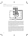
Figure 3–1. IDK Demo Block Diagram
Host GUI (CCS plug-in)
RTDX
Application Framework
Message handling task
Channel task
Passthask
I/O task
Channel manager
Algorithms
Capture/display driver
CSL + DSP/BIOS
In order for algorithms to work in a real-time system, there must be an application framework to connect algorithms with DSP hardware peripherals. In a typical DSP application, the framework is a software module or a group of software
modules that resides on top of algorithms and peripheral I/O drivers. It is usually responsible for getting input data from peripheral devices, passing the data
to algorithms for processing and sending the processed data to peripheral devices for output. The framework is also responsible for the creation, deletion,
configuration and execution of algorithm instances.
In simple, static applications, the framework is usually hard-wired and statically configured to run just a single algorithm or a fixed set of algorithms. However,
in dynamic, multichannel, multi-algorithm applications, the framework can be
fairly complicated. It is usually divided into multiple layers so that its core is application independent. This allows the same framework core to be used for a
range of different applications.
The framework layer in IDK applications includes all modules above the algorithms and the video capture and display driver, as shown in Figure 3-1. The
framework structures are slightly different among different demo scenarios.
Software Architecture – Applications Framework
3-3
Framework for Combining eXpressDSP-Compliant Algorithms
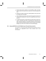
For example, in the Image Processing demo, there are four Channel Tasks,
one for each processing channel, while in the JPEG Loop-back demo, there
are only two Channel Tasks. Figure 3–2 shows the channel task layout of
these two demos. Also, I/O tasks and Message Handling tasks are different,
depending on whether the demo needs capture data input, or whether it handles a particular type of message.
Figure 3–2. Channel Task Layouts for JPEG Loop-Back Demo and
Image Processing Demo
3x3 convolution task
Loop-back task
Sobel edge detection task
Pass-through task
Binary threshold task
JPEG loop-back demo
Pass-through task
Image processing demo
To make the framework more general and scalable, and to make modules reusable, the framework modules are divided into two layers. The upper layer
is application specific, while the lower layer is application independent.
The upper layer includes all DSP/BIOS tasks and system initialization module,
which is the main() function. This layer is responsible to start the application,
to process host messages and to get I/O buffers from capture/display drivers
and pass them to “channels” for processing. This layer makes use of DSP/
BIOS task and semaphore objects for task scheduling and synchronization.
The lower layer of the framework is the Channel Manager (CM) module, which
directly interfaces with algorithms. Channel Manager is a generic algorithm
framework and responsible for the creation, deletion, execution and configuration of algorithm instances. An algorithm that is compliant with the
eXpressDSPt Algorithm Standard, and has a processing method that meets
Channel Manager’s criteria, can be plugged into it.
Channel Manager is independent of specific applications, algorithms and essentially the DSP hardware. All IDK demo applications use the same Channel
3-4
Framework for Combining eXpressDSP-Compliant Algorithms
Manager module. This is basically the same Channel Manager that is used in
the Multichannel Vocoder TDK (DSK version), with some minor API level
changes. Changes have been made to make it more general. New features
include support for request of multiple memory blocks, on-chip scratch buffer
and multiple heaps. Also, Channel Manager is now transparent to DSP cache
settings and essentially independent of hardware configurations, which
makes it possible to reuse it even on different hardware platforms.
Eventually, the Multichannel Vocoder TDK (DSK version) will be updated with
the changes made in Channel Manager for the IDK applications. The most important feature of Channel Manager is its built-in support for multichannel, multi-algorithm applications. It provides high-level APIs to register algorithms, to
open/close channels, to create/delete a group of algorithms instances in a
channel and to “execute” those instances. To optimize DSP memory usage
and to meet memory requirements of a wide range of DSP algorithms, Channel Manager manages two memory heaps, one located on-chip and one located off-chip. Channel Manager also supports parent instance to allow global
data sharable by all instances of the same algorithm. And, in order to use the
on-chip DSP memory more efficiently, Channel Manager overlays the on-chip
scratch buffer for all algorithm instances.
Software Architecture – Applications Framework
3-5
The IALG Interface
3.2 The IALG Interface
Since all algorithms must implement the IALG interface in order to plug into
Channel Manager, it is essential to have a good understanding of the standard
IALG interface before further discussions on Channel Manager details.
An algorithm is said to be eXpress-compliant if it implements the IALG Interface and observes all the programming rules in the algorithm standard. The
core of the IALG interface is the IALG_Fxns structure type, in which a number
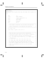
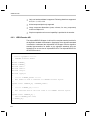
of function pointers are defined. Each eXpress-compliant algorithm must define and initialize a variable of type IALG_Fxns as shown below.
In IALG_fxns, algAlloc(), algInit() and algFree() are required, while other functions are optional.
typedef struct IALG_Fxns {
Void
*implementationId;
Void
(*algActivate)(IALG_Handle);
Int
(*algAlloc)(const IALG_Params *, struct IALG_Fxns **, IALG_MemRec
Int
(*algControl)(IALG_Handle, IALG_Cmd, IALG_Status *);
Void
(*algDeactivate)(IALG_Handle);
Int
(*algFree)(IALG_Handle, IALG_MemRec *);
Int
(*algInit)(IALG_Handle, const IALG_MemRec *, IALG_Handle, const
*);
IALG_Params *);
Void
(*algMoved)(IALG_Handle, const IALG_MemRec *, IALG_Handle, const
IALG_Params *);
Int
(*algNumAlloc)(Void);
} IALG_Fxns;
The algorithm implements the algAlloc() function to inform the framework of
its memory requirements by filling the memTab structure. It also informs the
framework whether there is a parent object for this algorithm. Based on the
information it obtains by calling algAlloc(), the framework then allocates the requested memory.
AlgInit() initializes the instance persistent memory requested in algAlloc(). After the framework has called algInit(), the instance of the algorithm pointed to
by handle is ready to be used.
3-6
The IALG Interface
To delete an instance of the algorithm pointed to by handle, the framework
needs to call algFree(). It is the responsibility of the algorithm responsibility to
set the addresses and the size of each memory block requested in algAlloc()
such that the application can delete the instance object without creating
memory leaks.
The parent object that implements the IALG interface is an important and useful feature of the eXpressDSP API. It was created primarily to allow the sharing
of global data between all instances of the same algorithm.
Software Architecture – Applications Framework
3-7
Integrating an Algorithm into the Channel Manager
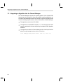
3.3 Integrating an Algorithm into the Channel Manager
The Channel Manager supports all required features of the eXpress DSP
Standard and is fairly generic. Most eXpressDSP-compliant algorithms can
work with Channel Manager without any changes. In general, algorithms must
meet the following requirements in order to work with the Channel Manager.
- The algorithm works on the C6711 DSK.
- The algorithm is eXpressDSP-compliant, i.e., it must implement the IALG
interface and observe all rules required by the eXpress DSP Algorithm
Standard.
- The algorithm provides the Channel Manager with a function pointer that
points to its processing function, which is in the form:
void* XXXApply(IALG_Handle handle, void* in, void* out)
3-8
Channel Manager Object Types
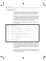
3.4 Channel Manager Object Types
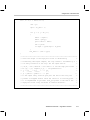
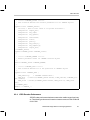
There are three basic object types in the Channel Manager: the algorithm object ALG_OBJ, the instance object INST_OBJ and the channel object
CHAN_OBJ.
The ALG_OBJ object inherits the IALG interface. It has a “process” method
and other information that the Channel Manager needs to create an algorithm
instance. The definition of ALG_OBJ is shown below:
typedef struct {
char
Name;
/*
void
*algFxns;
/* XDAIS IALG v–table */
void
(*process)();
/* execution method
void* algParams;
Name of the algorithm */
*/
/* pointer to the structure of the
algorithm’s creation parameters */
UINT32
InputCt;
/* number of inputs for the algorithm */
UINT32
OutputCt;
/* number of outputs */
UINT32
ContextSz;
/* total persistent data size */
UINT32
TableSz;
/* total constant table size */
InstCt;
/* number of instances currently running in the system
UINT32
*/
Void*
TableAddr;
instance */
/* global table address, or handle to the parent
} ALG_OBJ;
The INST_OBJ object encapsulates an algorithm instance. It has a pointer
pointing to its base ALG_OBJ and contains handles of that instance. It also has
a pointer to the status parameters structure of that instance. The definition of
INST_OBJ is shown below:
typedef struct {
ALG_OBJ AlgPtr;
/* pointer to the base algorithm object */
void
*ContextAddr;/* context pointer, or IALG handle to the algorithm
instance */
void*
algParams;/* pointer to the structure of status parameter of that
instance */
UINT32
CopyMode;
UINT32
DynamicID;
/* data copy mode, not used in C6211/C6711 version */
/* instance ID */
} INST_OBJ;
Software Architecture – Applications Framework
3-9
Channel Manager Object Types
The CHAN_OBJ object contains algorithm instances in a particular channel.
When a channel is ”executed”, it runs all instances in that channel in a serial
manner, so that the outputs of the pervious instance become the inputs of the
next one. The definition of CHAN_OBJ is shown below:
typedef struct {
char
Name;
/* name of the channel */
SIG_OBJ Sig;
/* signal object
*/
UINT32
CopyMode;
/* not used in C6211/C6711 version
UINT32
AlgCt;
/* number of instances in the channel */
INST_OBJ Algs[CM_MAX_CHA_ALGS];
/* instance handles
*/
*/
UINT32
InputCt;
/* number of inputs
*/
UINT32
OutputCt;
/* number of outputs
*/
UINT32
S;
/* completion signal mode
*/
} CHAN_OBJ;
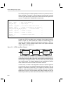
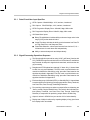
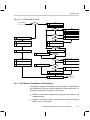
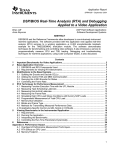
Consider the JPEG Loop-Back demo, consisting of two channel tasks as
shown in Figure 3–2. Each channel task contains one channel object. The
loop-back channel object consists of three algorithm instances, a JPEG encoder instance, a JPEG decoder instance and a color space conversion
instance, as shown in Figure 3–3:
Figure 3–3. JPEG Loop-Back Channel
JPEG encoder
JPEG decoder
Color space
conversion
In the loop-back channel, the output of the encoder instance feeds directly into
the decoder instance and the output of the decoder instance feeds directly into
the color space conversion instance. This is the reason they can be grouped
into a single channel. The Channel Manager is then responsible to execute
these instances and control the data flow between instances.
In other cases, it is better to have algorithm instances in separate channels
even when the output of one algorithm instance feeds into another. This can
happen in cases where output data of one instance is shared by multiple
instances. Again considering the JPEG Loop-Back demo as an example,
please refer to Figure 3–4 which shows three channel objects. One of the
channel objects is the loop-back channel discussed above, another one is the
3-10
Channel Manager Object Types
pass-through channel consisting of an instance of the color space conversion
algorithm. The third channel is the preprocessing channel, which consists of
an instance of the pre-scale algorithm to convert the input image from
640X240 4:2:2 to 320X240 4:2:0 for NTSC data, or from 768x288 4:2:2 to
384x288 4:2:0 for PAL data. This channel is located in the I/O task and it is a
separate channel because both the loop-back and the pass-through channels
share its output data.
Figure 3–4. JPEG Loop-Back Demo Channels and I/O Buffers
Capture buffer
Intermediate buffer
Display buffer
JPEG loop-back
channel
Pre-scale
channel
Pass-through
channel
Software Architecture – Applications Framework
3-11
Channel Manager Memory Management
3.5 Channel Manager Memory Management
This section describes various aspects of Channel Manager memory management, including the C6711 DSK memory architecture, data memory requirements of algorithms used in the IDK, memory heaps management by the
Channel Manager, creation and deletion of algorithm instances by the Channel Manager, and parent instance support.
3.5.1
C6711 DSK Memory Architecture
The TMS320C6211/6711 DSP employs a two-level memory architecture for
on-chip program and data access. The first level (L1) has dedicated 4 KBytes
each program and data caches, L1P and L1D respectively. The second level
memory (L2) is a 64 KBytes memory-block that is sharable by both program
and data. The L2 memory is divided into four 16-KByte blocks. Each of the four
blocks can be independently configured as either cache or memory mapped
RAM. This feature is ideal for efficient implementation of imaging/video applications. The C6711 DSK has 16 MBytes external SD-RAM operating at
100MHz.
3.5.2
Data Memory Requirements of IDK Algorithms
Image processing algorithms typically work on very large quantities of data,
with sizes far larger than the on-chip memory space on most typical processors. On the other hand, at any given time, an algorithm is only processing a
small portion of the entire image, such as an 8x8 block or a vertical/horizontal
line. Data access is usually localized and predictable. This makes it possible
for algorithms to bring data to fast internal data memory before processing it
and send it back out to external memory after the processing is done. The fastest way to perform the data movement is Direct Memory Access (DMA). By
using double buffering schemes, most or all overhead of data movement can
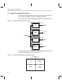
be eliminated by doing the DMA transfer in the background. Figure 3–5 shows
the system memory layout for a typical image-processing algorithm.
Figure 3–5. Split Cache/SRAM Mode with QDMA Data Transfer
Internal L2 Memory (64 Kbytes)
SRAM
Cache
3-12
External SDRAM (16M bytes)
QDMA transfer
service
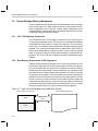
Channel Manager Memory Management
As shown in Figure 3–5, the on-chip SRAM operates in split mode, with part
of it configured as RAM and the rest as L2 cache for both program and data.
The on-chip RAM is primarily used as internal scratch data buffers. At run-time,
algorithms call DMA data service functions (CSL DAT Module) to transfer data
between internal and external memory. If the application consists of multiple
processing channels, then all channels share the same internal scratch
memory buffer. Note that the algorithms themselves are responsible for managing their on-chip/off-chip data transfer.
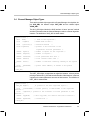
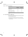
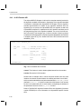
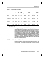
Table 3–1 shows the L2 operation modes of the C6211/C711 DSP for various
IDK demos. Since the JPEG loop-back demo requires less than 16KB on-chip
scratch buffer (about 13KB), it operates in 48KB cache/16KB RAM mode to
ensure high performance. The other scenarios operate in 32KB cache/32KB
RAM mode because algorithms in those demos require more than 16KB onchip memory.
Table 3–1. C6211/C6711 L2 Operation Modes for IDK Demos
3.5.3
Demo Scenarios
L2 Operation Mode (Cache/RAM)
JPEG Loop-Back
48 Kbytes / 16 Kbytes
H.263 Loop-Back
32 Kbytes / 32 Kbytes
Multichannel H.263 Decoder
32 Kbytes / 32 Kbytes
Image Processing
32 Kbytes / 32 Kbytes
Forward Wavelet Transform
32 Kbytes / 32 Kbytes
Internal and External Heaps
As shown in the previous section, algorithms in the IDK require memory blocks
in both on-chip and off-chip data memory space. To accommodate these requirements, and to optimize the usage of the limited on-chip L2 RAM space,
the Channel Manager usually maintains two memory heaps. The internal heap
is located in on-chip L2 RAM and the external heap is located in off-chip SDRAM.
The Channel Manager uses DSP/BIOS MEM module API functions to manage
memory allocation and de-allocation on the two heaps. The heaps are created
in the DSP/BIOS CDB file and passed to Channel Manager by calling the
CM_Control() function. By default, or if no heap IDs are passed into the Channel Manager, it uses memalign() and free() functions in the run-time support
library. These two functions make use of the traditional heap defined in that
same library. The Channel Manager allocates memory blocks on these two
Software Architecture – Applications Framework
3-13
Channel Manager Memory Management
heaps for algorithm instances according to their memory requirements. Each
instance is then responsible to initialize its memory blocks and to manage data
transfer between its on-chip and off-chip data memory blocks. All algorithms
in the IDK use CSL DAT module API functions for data transfer services.
3.5.4
Creation and Deletion of an Algorithm Instance
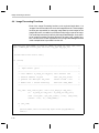
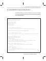
Each eXpressDSP-compliant algorithm must implement the algAlloc() function in its IALG interface implementation. To create an instance of that algorithm, the Channel Manager uses that function to find out the memory requirements of the algorithm. The prototype of the algAlloc() function in an algorithm
named XXX is shown below:
Int
XXXAlloc(const IALG_Params *params ,
struct IALG_Fxns
**fxns,
IALG_MemRec
memTab[]);
In the XXXAlloc() function, the algorithm fills out the memTab[] array with its
memory requests, and returns with the number of memory blocks that the
framework must allocate in order to create an instance of that algorithm. Each
MemRec entry corresponds to a request of one memory block. It contains the
size, alignment, space, and attributes information of that memory block.
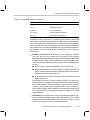
Four types of data memory requests are currently supported in the Channel
Manager:
- Internal Persistent Memory is allocated directly on the internal heap.
- External Persistent Memory is allocated directly on the external heap.
- Internal Scratch Memory is overlaid on the internal scratch buffer, which
is allocated on the internal heap according to the maximum requested size
of internal scratch memory space among all registered algorithms.
- External Scratch Memory is allocated directly on the external heap.
Following are the steps to create a new algorithm instance:
- Register the algorithm to Channel Manager by calling the CM_RegAlg()
funciton and a handle of that algorithm is returned by Channel Manager.
In this step the Channel Manager calls the algAlloc() function of the algorithm to find out whether the algorithm has a parent object. If so, the Channel Manager creates a parent instance for that algorithm. The Channel
Manager also finds out if the algorithm requests an on-chip scratch buffer.
If so, the Channel Manager gets the size of the requested buffer and
3-14
Channel Manager Memory Management
compares it with the maximum size requested by previously registered algorithms. The maximum size is updated if the current algorithm requested
a bigger buffer.
- Call CM_SetAlg() to set the algorithm in a channel. Inside Channel Man-
ager a new instance of that algorithm is then created and is attached to that
particular channel. In this step the Channel Manager calls the algAlloc()
function of the agorithm again and checks each entry in the memTab[]
array. It then allocates persistent memory blocks and external scratch
memory blocks on either internal on external heap according to the
memory requests of the algorithm. It also allocates a scratch buffer on the
internal heap space using the maximum scratch-size information collected in CM_RegAlg() earlier, if the scratch buffer has not been allocated
yet. If all memory allocations succeed, the Channel Manager calls the algInit() function of the algorithm to initialize the allocated memory blocks and
completes the creation of a new instance of that algorithm.
The deletion of algorithm instances also happens in CM_SetAlg() function. Before new algorithm instances are set to a channel, old instances must be deleted. Channel Manager calls the algorithm’s algFree() function to get the base
addresses of all allocated memory blocks in that instance. It then frees all
blocks that are either persistent blocks or external scratch blocks. Parent
instance and internal scratch buffer are not deleted because they are shared
resources.
3.5.5
Parent Instance Support
Note that the second parameter of the XXXAlloc() function above is a pointer
to a pointer of an IALG_Fxns structure. This IALG v-table represents the parent object of the algorithm, if it has one. The eXpress Algorithm Standard allows an algorithm to optionally implement a second IALG interface, which can
be used to create a parent instance of that algorithm. The parent instance of
an algorithm usually contains global data sharable by all instances of that algorithm, such as global look-up table, etc.
The Channel Manager fully supports the creation of parent instances. In the
CM_RegAlg() function, the Channel Manager calls the XXXAlloc() function of
an algorithm and checks whether *fxns points to a valid v-table. If so, the Channel Manager creates the parent instance for that algorithm, in a manner similar
to the creation of an ordinary algorithm instance. The handle of the parent
instance is then attached to that algorithm object and later passed to all
instances of that algorithm when they are created.
Software Architecture – Applications Framework
3-15
Channel Manager API Functions
3.6 Channel Manager API Functions
- CM_Init, Channel Manager module initialization.
- CM_Open, create a new channel object.
- CM_Close, delete the channel object.
- CM_SetAlgs, set algorithms in the channel. Old instances in the channel
are deleted and new instances are created according to the new algorithm
settings.
- CM_GetAlgs, get algorithm settings in the channel.
- CM_RegAlg, register an algorithm to Channel Manager.
- CM_Exec, execute all algorithms in the channel object.
- CM_InstCtrl, set or get the status parameters of a specific instance in the
channel.
- CM_Control, set or get Channel Manager global configuration data.
3-16
CM_Close
3.6.1
API Reference
CM_Init
Initializes Channel Manager module
Prototype
BOOL CM_Init()
Arguments
none
Return Value
BOOL
Description
Initializes the Channel Manager module. Must be called at least once before
any other CM API functions can be called.
CM_Open
TRUE – function succeeded
FALSE – function failed
Creates new channel object
Prototype
HANDLE CM_Open(char
UINT32
Flag,
SIG_OBJ *Signal)
Arguments
char *Name
Flag
SIG_OBJ *Signal
Name of the channel
TBD
Signal object used to post application upon each
completion of running the channel.
Return Value
HANDLE
Returns a handle to the open channel. INV is returned
upon failure.
Description
Create a new channel object.
CM_Close
*Name,
Deletes channel object
Prototype
Void CM_Close(HANDLE hCha)
Arguments
HANDLE hCha
Return Value
none
Description
Delete the channel object.
Handle to the channel.
Software Architecture – Applications Framework
3-17
CM_SetAlgs
CM_SetAlgs
Assigns set of algorithms to channel
Prototype
BOOL CM_SetAlgs(HANDLE hCha,
UINT32 Count,
HANDLE Algs[])
Arguments
HANDLE hCha
UINT32 Count
HANDLE Algs[]
Handle to an open channel.
Number of algorithms to assign
An array of algorithm handles to assign
Return Value
BOOL
TRUE – function succeeds
FALSE – function fails
Description
Assigns a set of algorithms to the channel. Channel Manager creates algorithm instances according to algorithms specified in the Algs[].
CM_GetAlgs
Gets number of algorithms and handles to algorithms in channel
Prototype
UINT32 CM_GetAlgs(HANDLE hCha,
HANDLE Algs[]);
Arguments
HANDLE hCha
HANDLE Algs[]
Handle to an open channel.
An array of handles to all algorithms in this channel
Return Value
UINT32
Number of algorithms in the channel
Description
Gets number of algorithms and handles to those algorithms in the channel.
Get or set the status of an algorithm instance in a channel. Inside Channel
Manager calls that instance’s algControl() function.
3-18
CM_InstCtrl
CM_RegAlg
Registers algorithm with Channel Manager
Prototype
HANDLE CM_RegAlg(char *Name, void *algFxns,
void (*process)(), void *algParams,
UINT32 InputCt, UINT32 OutputCt);
Arguments
char *Name
void *algFxns
Void*(*process)()
Void* algParams
UINT32 InputCt
UINT32 OutputCt
Name of the algorithm
Pointer to XDAIS IALG function pointer table
Function pointer to algorithm processing routine
Pointer to XDAIS algorithm parameter structure
Number of algorithm inputs
Number of algorithm outputs
Return Value
HANDLE
Returns a handle to the registered algorithm. Returns
INV if algorithm could not be registered.
Description
Registers an algorithm with Channel Manager. Channel Manager gets to know
this algorithm and it collects all information it needs to create and execute an
instance of the algorithm later. All CM_RegAlg() calls must be prior to any
CM_SetAlg() call. In other words, all algorithms must register with Channel
Manager before any of them can be assigned to a channel.
CM_Exec
Executes channel
Prototype
BOOL CM_Exec(HANDLE hChan, FRM_OBJ *In[], FRM_OBJ *Buffs[],
FRM_OBJ *Out[], UINT32 Post);
Arguments
HANDLE hChan
FRM_OBJ *In[]
FRM_OBJ *Buffs[]
FRM_OBJ *Out[]
UINT32 Post
Handle to an open channel.
An array of pointers to input frames.J
An array of pointers to intermediate buffers
An array of pointers to output frames
Post value
Return Value
BOOL
TRUE – function succeeded
FALSE – function failed
Description
Executes channel
CM_InstCtrl
Prototype
Get or set status of algorithm instance in channel
BOOL CM_InstCtrl(HANDLE hCha,
int InstNo,
Software Architecture – Applications Framework
3-19
CM_Control
int Cmd,
void* InstStatus)
Arguments
HANDLE hCha
int InstNo
int Cmd
Handle to the channel
Number to identify the algorithm instance in the channel
Control command specific for that particular algorithm
type
Pointer to the instance status structure
void* InstStatus
Return Value
BOOL
Description
Get or set the status of an algorithm instance in the channel. Internally CM calls
that algorithm’s algControl() function.
CM_Control
TRUE – function succeeds
FALSE – function fails
Executes CM control function
Prototype
UINT32 CM_Control(CM_CTRL_ID Id, ...);
Arguments
CM_CTRL_ID id
Control ID, may be one of the following:
CM_RESET
CM_GET_CHA_INFO
CM_GET_ALG_INFO
CM_SET_INTERNAL_HEAP
CM_SET_EXTERNAL_HEAP
-
Additional Arguments
on control Id
none
HANDLE* AlgPtr
CM_RESET
CM_GET_CHA_INFO
CM_ALG_INFO *StatsPtr
CHAN_OBJ *ChaPtr
CM_CHA_INFO *StatsPtr
CM_GET_ALG_INFO
Int HeapID
CM_SET_EXTERNAL_HEAP
int HeapID
CM_SET_INTERNAL_HEAP
Return Value
UINT32
Description
Executes a CM control function.
3-20
Return value depends on control ID.
Chapter 4
Software Architecture – Algorithms Creation
This chapter describes algorithm creation in the software architecture.
Topic
Page
4.1
Overview . . . . . . . . . . . . . . . . . . . . . . . . . . . . . . . . . . . . . . . . . . . . . . . . . . . . . 4-2
4.2
eXpressDSP API Wrapper . . . . . . . . . . . . . . . . . . . . . . . . . . . . . . . . . . . . . 4-4
4.3
Algorithm . . . . . . . . . . . . . . . . . . . . . . . . . . . . . . . . . . . . . . . . . . . . . . . . . . . . 4-8
4.4
Image Processing Functions . . . . . . . . . . . . . . . . . . . . . . . . . . . . . . . . . . 4-10
4.5
ImageLIB or Custom Kernels . . . . . . . . . . . . . . . . . . . . . . . . . . . . . . . . . 4-15
4.6
Image Data Manager . . . . . . . . . . . . . . . . . . . . . . . . . . . . . . . . . . . . . . . . . 4-19
4-1
Overview
4.1 Overview
ImageLIB functions based standard algorithms may be created using the software architecture shown in Figure 4–1:
Figure 4–1. Software Architecture for ImageLIB Functions-Based Standard Algorithms
eXpressDSP API wrapper
Algorithm
Image processing functions
ImageLIB or custom kernels
Image data manager
CSL
- The top-most layer of this hierarchical architecture is the eXpressDSP
API Wrapper. This is the interface available to other algorithms or users
of the eXpressDSP-compliant algorithm.
- The next layer is the actual Algorithm. It typically invokes one or more
Image Processing Functions. The ordering of the functions, and data
passing between the functions is controlled by the standard algorithm.
- An Image Processing Function is a “wrapper” around one or more Imag-
ing Kernels, and is responsible for managing data I/O for the kernels.
- ImageLIB or Custom Kernels are the core processing operations. Typi-
cally, they are DSP code that has been highly optimized for performance.
Many of these kernels are contained in the TI ImageLIB software, while
others are custom software for specific applications.
- Image Data Manager is a set of library routines that offer abstraction for
double buffering of DMA requests, to efficiently move data in the background during processing. They have been developed to help remove the
burden from the user of having to perform pointer updates in the code.
Image Data Manager uses CSL DAT calls to move data between external
and internal memory during the course of processing.
To illustrate the use of various layers of software shown above, we use the 2D
Wavelet Transform IDK algorithm as an example. The sequence of operations
performed is shown in Figure 4-2:
4-2
Overview
Figure 4–2. 2D Wavelet Transform
Horizontal
wavelet
transform
Vertical
wavelet
transform
Enhance/
pixel
saturate
Software Architecture – Algorithms Creation
4-3
eXpressDSP API Wrapper
4.2 eXpressDSP API Wrapper
The eXpressDSP API Wrapper is derived from template material provided in
the algorithm standard documentation. Knowledge of the algorithm standard
is essential to understand the eXpressDSP API wrapper. See the algorithm
standard documentation for details on the algorithm standard.
For the wavelet example, the eXpressDSP API Wrapper consists of the files
wavelet_ti.h and iwavelet.h, shown below. Descriptions of the file elements
are included:
/*
*
======== wavelet_ti.h ========
*
Interface for the Wavelet_TI module; TI’s implementation
*
of the IWavelet interface
*/
#ifndef Wavelet_TI_
#define Wavelet_TI_
#include <iwavelet.h>
#include <ialg.h>
/*
*
======== Wavelet_TI_IALG ========
*
TI’s implementation of the IALG interface for Wavelet
*/
extern IALG_Fxns Wavelet_TI_IALG;
/*
*
======== Wavelet_TI_IWavelet ========
*
TI’s implementation of the IWavelet interface
*/
extern IWavelet_Fxns Wavelet_TI_IWavelet;
#endif /* Wavelet_TI_ */
4-4
eXpressDSP API Wrapper
/*
*
======== iwavelet.h ========
*
IWavelet Interface Header
*/
#ifndef IWavelet_
#define IWavelet_
#include <std.h>
#include <xdas.h>
#include <ialg.h>
typedef enum img_type
{
FLDS,
PROG
} IMG_TYPE;
/*
*
======== IWavelet_Handle ========
*
This handle is used to reference all Wavelet instance objects
*/
typedef struct IWavelet_Obj *IWavelet_Handle;
/*
*
======== IWavelet_Obj ========
*
This structure must be the first field of all Wavelet instance objects
*/
typedef struct IWavelet_Obj {
struct IWavelet_Fxns *fxns;
} IWavelet_Obj;
/*
*
======== IWavelet_Status ========
*
Status structure defines the parameters that can be changed or read
*
during real–time operation of the algorithm.
*/
typedef struct IWavelet_Status {
Int size; /* must be first field of all status structures */
int
img_cols;
Software Architecture – Algorithms Creation
4-5
eXpressDSP API Wrapper
int
img_rows;
short*
qmf_ext;
short*
mqmf_ext;
int
scale;
IMG_TYPE
img_val;
} IWavelet_Status;
/*
*
======== IWavelet_Cmd ========
*
The Cmd enumeration defines the control commands for the Wavelet
*
control method.
*/
typedef enum IWavelet_Cmd {
IWavelet_GETSTATUS,
IWavelet_SETSTATUS
} IWavelet_Cmd;
/*
*
======== IWavelet_Params ========
*
This structure defines the creation parameters for all Wavelet objects
*/
typedef struct IWavelet_Params {
Int size; /* must be first field of all params structures */
int
img_cols;
int
img_rows;
const short*
qmf_ext;
const short*
mqmf_ext;
int
scale;
IMG_TYPE
img_val;
} IWavelet_Params;
/*
*
======== IWavelet_PARAMS ========
*
Default parameter values for Wavelet instance objects
*/
extern IWavelet_Params IWavelet_PARAMS;
/*
4-6
eXpressDSP API Wrapper
*
======== IWavelet_Fxns ========
*
This structure defines all of the operations on Wavelet objects
*/
typedef struct IWavelet_Fxns {
IALG_Fxns ialg;
/* IWavelet extends IALG */
XDAS_Bool
(*control)(IWavelet_Handle handle, IWavelet_Cmd cmd, IWavelet_Status *status);
XDAS_Int32
out);
(*apply)(IWavelet_Handle handle, XDAS_Int8** in, XDAS_Int8*
} IWavelet_Fxns;
#endif /* IWavelet_ */
Software Architecture – Algorithms Creation
4-7
Algorithm
4.3 Algorithm
The algorithm for the Wavelet Transform example has the form shown below:
void wavelet_codec(IMAGE *in_image_ev, IMAGE *in_image_od,
IMAGE *out_image, SCRATCH_PAD *scratch_pad,
WAVE_PARAMS *wave_params, img_type img_val);
where
in_image_ev: pointer to structure for even field
in_image_od: pointer to structure for odd field
out_image:
pointer to structure for output image
scratch_pad: pointer to structure for scratch pad
wave_params: pointer to structure for wavelet codec
img_type:
FLDS for odd/even fields and PROG for progressive.
The structures referred to above are defined in Appendix D. If img_type is
PROG then in_image_od is ignored and the image is assumed to be contiguous starting at the address in_image_ev. If img_type is FLDS, then half the
rows are assumed to be in the even field and the other half in the odd field.
Shown below is an example of how a user may make use of this, including handling of DMA open and close:
DAT_Open(0, DAT_PRI_LOW, 0);
wavelet_codec(&in_image_ev, &in_image_od, &out_image, &scratch_pad,
&wave_params, FLDS);
DAT_Close(0, DAT_PRI_LOW, 0);
See Appendix D for a full driver code example.
The Algorithm in turn invokes the multiple Image Processing Functions that
compose the overall algorithm, as shown below for the example of Wavelet
Transform:
void wavelet_codec(IMAGE *in_image_ev, IMAGE *in_image_od, IMAGE *out_image,
SCRATCH_PAD *scratch_pad, WAVE_PARAMS *wave_params, img_type img_type_val)
{
(internal memory initialization);
4-8
Algorithm
/*–––––––––––––––––––––––––––––––––––––––––––––––––––––––––––––––––––––––*/
/* Perform the horizontal wavelet transform on the whole image by
/* calling wave_horz_image, to perform 1 scale of analysis.
*/
*/
/*–––––––––––––––––––––––––––––––––––––––––––––––––––––––––––––––––––––––*/
wave_horz_image(in_image_ev, in_image_od, qmf_int, mqmf_int, scratch_pad,
0, img_type_val);
/*–––––––––––––––––––––––––––––––––––––––––––––––––––––––––––––––––––––––*/
/* Perform the vertical wavelet transform on the whole image by calling
/*
wave_vert_image, to perform 1 scale of analysis.
*/
*/
/*–––––––––––––––––––––––––––––––––––––––––––––––––––––––––––––––––––––––*/
wave_vert_image(in_image_ev, in_image_od, qmf_int, mqmf_int, scratch_pad,
0, img_type_val);
/*–––––––––––––––––––––––––––––––––––––––––––––––––––––––––––––––––––––––*/
/* Perform the wavelet_display of the resulting wavelet transform by
*/
/* determining the maximum and minimum of the sub–images, and
*/
/* re–normalizing to scale pixels to range 0–255.
*/
/*–––––––––––––––––––––––––––––––––––––––––––––––––––––––––––––––––––––––*/
wavelet_display(out_image, scratch_pad, wave_params);
}
Software Architecture – Algorithms Creation
4-9
Image Processing Functions
4.4 Image Processing Functions
Each of the Image Processing functions, such as those listed above, is a
“wrapper” function around one or more core ImageLIB kernels. These wrapper
functions are responsible for managing image data input and output for the
ImageLIB function, to enable it to process an entire image or part of an image.
The actual data movement is done by the Image Data Manager. As an example of Image Processing Functions structure, the wave_horz_image() function, is shown below. A fuller explanation of the Image Data Manager invoked
in the example below is provided in section 4.6.
void wave_horz_image(IMAGE *in_image_ev, IMAGE *in_image_od, short *qmf, short
*mqmf, SCRATCH_PAD *scratch_pad, int scale, img_type img_type_val)
{
(initialization and control code);
if (!scale)
{
/*–––––––––––––––––––––––––––––––––––––––––––––––––––––––––––––––––––*/
/*
Input Stream: i_dstr
*/
/*–––––––––––––––––––––––––––––––––––––––––––––––––––––––––––––––––––*/
/* Start address: in_image_ev–>img_data, Size: external size
*/
/* Internal address: int_mem
Size: pix_char_offset
*/
/* Quantum: cols Multiple: num_lines
Stride: stride * cols
*/
/* Window size: 1 (Double buffering)
Direction: DSTR_INPUT
*/
/*–––––––––––––––––––––––––––––––––––––––––––––––––––––––––––––––––––*/
err_code = dstr_init(&i_dstr, (void *)(in_image_ev–>img_data),
(2 *
in_image_ev–>img_rows * in_image_ev–>img_cols),
(void *)(int_mem), (pix_char_offset), (cols), (num_lines),
(stride * cols), (1), (DSTR_INPUT));
if (err_code)
{
fprintf(stderr,”error initializing input stream pix_expand\n”);
exit(3);
4-10
Image Processing Functions
}
/*–––––––––––––––––––––––––––––––––––––––––––––––––––––––––––––––––––*/
/*
Output Stream: o_dstr
*/
/*–––––––––––––––––––––––––––––––––––––––––––––––––––––––––––––––––––*/
/* Start address: ext_horz_start_ev, Size: external size/2
*/
/* Internal address: ptr_wave_horz_start Size: 4 x num_lines x cols
*/
/* Quantum: 2 x cols Multiple: num_lines Stride: 4 x cols
*/
/* Window size: 1 (Double buffering) Direction: DSTR_OUTPUT
*/
/*–––––––––––––––––––––––––––––––––––––––––––––––––––––––––––––––––––*/
err_code = dstr_init(&o_dstr, (void *) (ext_horz_start_ev),
(ext_size >> 1), (void *) (ptr_wave_horz_start),
(4 * cols * num_lines), (cols * 2), (num_lines),
(cols * 4), (1), (DSTR_OUTPUT));
if (err_code)
{
fprintf(stderr,”error initializing output stream horizontal
wavelet\n”);
printf(”err_code:%d \n”, err_code);
exit(4);
}
}
Software Architecture – Algorithms Creation
4-11
Image Processing Functions
/*––––––––––––––––––––––––––––––––––––––––––––––––––––––––––––––––––––––––––*/
/* Begin horizontal wavelet transform. When using Image Data Manager
*/
/* the first call to put merely returns the first available buffer to
*/
/* write to. Here dstr_put_2D and dstr_get_2D are used to obtain the
*/
/* next available output/input buffers. For each input buffer
*/
/* pixel_expand is performed by issuing 1 call to process
*/
/* cols * num_lines pixels, while the horizontal wavelet is called
*/
/* num_lines times, and incrementing the input and output pointers by
*/
/* cols after iteration
*/
/*––––––––––––––––––––––––––––––––––––––––––––––––––––––––––––––––––––––––––*/
for ( i = 0; i < (rows / num_lines); i++)
{
/*––––––––––––––––––––––––––––––––––––––––––––––––––––––––––––––––––––––*/
/* Get output buffer to write to by calling put_2D routine.
*/
/*––––––––––––––––––––––––––––––––––––––––––––––––––––––––––––––––––––––*/
out_data = (short *) dstr_put_2D(&o_dstr);
/*––––––––––––––––––––––––––––––––––––––––––––––––––––––––––––––––––––––*/
/* If it is the first scale of analysis, obtain input pointer to array
*/
/* of pixels and perform pixel_expand, followed by num_lines
*/
/* calls to the horizontal wavelet, to process each line one at a time
*/
/*––––––––––––––––––––––––––––––––––––––––––––––––––––––––––––––––––––––*/
if (!scale)
{
/*–––––––––––––––––––––––––––––––––––––––––––––––––––––––––––––––––––*/
/* Get char buffer and perform pixel expand by calling ImageLIB
*/
/* pixel_expand_asm routine, writing the array of expanded shorts
/* into pix_expand.
4-12
*/
*/
Image Processing Functions
/*–––––––––––––––––––––––––––––––––––––––––––––––––––––––––––––––––––*/
in_ch_data = (unsigned char *) dstr_get_2D(&i_dstr);
pix_expand_asm(cols * num_lines, in_ch_data, ptr_pix_expand);
/*–––––––––––––––––––––––––––––––––––––––––––––––––––––––––––––––––––*/
/* Call the horizontal wavelet once per line, num_lines times to
*/
/* perform horizontal wavelet and write out output into the output
*/
/* array. Increment input and output pointers by cols after every
*/
/*
iteration of the loop.
*/
/*–––––––––––––––––––––––––––––––––––––––––––––––––––––––––––––––––––*/
for ( j = 0; j < num_lines; j++)
{
ptr_wave = ptr_pix_expand + ( j * cols);
ptr_out
= out_data
+ ( j * cols);
wave_horz_asm(ptr_wave,qmf, mqmf, ptr_out, cols);
}
}
/*–––––––––––––––––––––––––––––––––––––––––––––––––––––––––––––––––––––*/
/* If half the iterations of this loop have been completed, then
*/
/* perform rewind using Image Data Manager, and start fetching from
*/
/* new location. This performs fetching of the odd field in case
*/
/* of odd/even field case or from odd line for progressive.
*/
/*–––––––––––––––––––––––––––––––––––––––––––––––––––––––––––––––––––––*/
if ( i == ((rows / num_lines) >> 1 ) – 1)
{
/*––––––––––––––––––––––––––––––––––––––––––––––––––––––––––––––––––*/
/* Commit last chunk that was written, rewind input and output
/* streams to their respective rewind addresses.
Software Architecture – Algorithms Creation
*/
*/
4-13
Image Processing Functions
/*––––––––––––––––––––––––––––––––––––––––––––––––––––––––––––––––––*/
dstr_put_2D(&o_dstr);
dstr_rewind(&i_dstr, in_rewind, DSTR_INPUT, 1);
dstr_rewind(&o_dstr, out_rewind, DSTR_OUTPUT, 1);
}
}
/*––––––––––––––––––––––––––––––––––––––––––––––––––––––––––––––––––––––*/
/*
Commit last set of buffers and close output stream.
*/
/*––––––––––––––––––––––––––––––––––––––––––––––––––––––––––––––––––––––*/
dstr_put_2D(&o_dstr);
dstr_close(&o_dstr);
}
4-14
ImageLIB or Custom Kernels
4.5 ImageLIB or Custom Kernels
ImageLIB or Custom Kernels are the core image processing utilities. Many of
these kernels are contained in the TI ImageLIB software, while others are custom software for specific applications. They typically rely on wrapper functions
such as the Image Processing Functions described above, to provide them input data and take their output data. Continuing with the Wavelet Transform example, the first ImageLIB kernel utilized is:
void pix_expand_asm (int n, unsigned char *in_data, short
*out_data);
where ‘n’ is number of samples processed, ‘in_data’ is pointer to input array
(unsigned chars), and ‘out_data’ is pointer to output array (shorts).
The kernel pix_expand_asm() takes an array of unsigned chars (pixels) and
zero extends them up to 16 bits to form shorts. Typical Imaging Kernels are
implemented in optimized assembly code.
Behavioral C code for the kernel pix_expand_asm() is provided below:
void pix_expand_asm (int n, unsigned char *in_data, short *out_data)
{int j;
for (j = 0; j < n; j++)
out_data[j] = (short) in_data[j];
}
Another key kernel used in the Wavelet Transform example is:
void wave_horz_asm (short *in_data, short *qmf, short
*mqmf, short *out_data, int cols );
where ‘in_data’ is a pointer to one row of input pixels, ‘qmf’ is a pointer to qmf
filter-bank for low-pass filtering, ‘mqmf’ is a pointer to mirror qmf filter bank for
high-pass filtering, ‘out_data’ is a pointer to row of detailed/reference decimated outputs, and ‘cols’ is the number of columns in the input image.
The kernel wave_horz_asm() performs a 1-D Periodic Orthogonal Wavelet decomposition. It also performs the row decomposition component of a 2D wavelet transform. An input signal x[n] is low pass and high pass filtered and the
resulting signals decimated by factor of two. This results in a reference signal
r1[n] which is the decimated output obtained by dropping the odd samples of
the low pass filter output and a detail signal d[n] obtained by dropping the odd
samples of the high-pass filter output. A circular convolution algorithm is implemented and hence the wavelet transform is periodic. The reference signal and
the detail signal are each half the size of the original signal. Behavioral C code
for the kernel wave_horz_asm() is provided below:
Software Architecture – Algorithms Creation
4-15
ImageLIB or Custom Kernels
#define Qpt 15
#define Qr 16384
void wave_horz( short *in_data, short *qmf, short *mqmf, short *out_data, int
cols)
{
int
i;
short
*xptr = in_data;
short
*x_end = &in_data[cols – 1];
int
j, sum, prod;
short
xdata, hdata;
short
*filt_ptr;
int
M = 8;
/**********************************************************************/
/* iters: number of iterations = half the width of the input line
*/
/* xstart: starting point for the high pass filter input data
*/
/**********************************************************************/
int
iters = cols;
short *xstart = in_data + (cols – M) + 2;
/**********************************************************************/
/* Since the output of the low pass filter is decimated by
*/
/* eliminating odd output samples, the loop counter i increments by
*/
/* 2 for every iteration of the loop. Let the input data be
*/
/* {d0 ,...d7 } and the low pass filter be {h0 ,...h7 }. Outputs y0 ,y1 ,... */
/* are generated as:
*/
/* y0 = h0 d0 + h1 d1 + h2 d2 + h3 d3 + h4 d4 + h5 d5 + h6 d6 + h7 d7
*/
/* y1 = h0 d2 + h1 d3 + h2 d4 + h3 d5 + h4 d6 + h5 d7 + h6 d8 + h7 d9
*/
/* If the input array access d goes past the end of the array
*/
/* the pointer is wrapped around. Since the filter is in floating
*/
/* point it is implemented in Q15 math. Qr is the associated
*/
/* round value.
*/
/**********************************************************************/
4-16
ImageLIB or Custom Kernels
for ( i = 0; i < iters; i+= 2)
{
sum = Qr;
xptr = in_data + i;
for (j = 0; j < M; j++)
{
xdata = *xptr++;
hdata = qmf[j];
prod = xdata * hdata;
sum += prod;
if (xptr > x_end) xptr = in_data;
}
*out_data++ = (sum >> Qpt);
}
/**********************************************************************/
/* Since the output of the high pass filter is decimated by
*/
/* eliminating odd output samples, the loop counter I increments by 2 */
/* for every iteration of the loop. Let the input data be
*/
/* {d0 ,d1 ,...dN–1 } where N = cols and M = 8. Let the high pass filter
*/
/* be {g0 ,...g7 }. Outputs y0 ,y1 ,... are generated as:
*/
/* y0 = g7 dN–M+2 + g6 dN–M+1 +....+ g0 d1
*/
/* y1 = g7 dN–M+2 + g6 dN–M+1 +....+ g0 d1
*/
/* If the input array access d goes past the end of the array the
*/
/* pointer is wrapped around. Since the filter is in floating point
*/
/* it is implemented in Q15 math. Filt_ptr points to the end of the
*/
/* high–pass filter array and moves in reverse direction.
*/
/**********************************************************************/
Software Architecture – Algorithms Creation
4-17
ImageLIB or Custom Kernels
for ( i = 0; i < iters; i+= 2)
{
sum = Qr;
filt_ptr = mqmf + (M – 1);
xptr = xstart;
xstart += 2;
if (xstart > x_end) xstart = in_data;
for (j = 0; j < M; j++)
{
xdata = *xptr++;
hdata = *filt_ptr––;;
prod = xdata * hdata;
if (xptr > x_end) xptr = in_data;
sum += prod;
}
*out_data++ = (sum >> Qpt);
}
}
4-18
Image Data Manager
4.6 Image Data Manager
Image Data Manager (IDM) is a set of library routines that offer abstraction for double buffering DMA
requests, to efficiently move data in the background during processing. They have been developed to
help remove the burden from the user of having to perform pointer updates in the code. IDM functions
use DAT Calls from CSL to move data between external and internal memory. They can be extended in
future to use EDMA/DMA calls as appropriate based on the device.
The following IDM functions are currently defined:
- dstr_open: Open an input/output image data stream to bring data from
external to internal memory or vice versa.
- dstr_get: Bring data from external to intenal memory allowing for either
one line at a time or multiple lines at a time without any offset between
them. This function should only bre used on ainput stream. The behaviour
of this function when used on an output stream cannot be guaranteed.
- dstr_get_2d: Bring data from external to internal memory allowing for
etither one line at a time, or multiple lines at a time, with no/fixed offset
between the lines. This function should only be used on an input stream.
The behaviour of this function when used on an output stream cannot be
guaranteed.
- dstr_put: Commit data from internal memory to external memory either
one line at a time, or multiple lines without any offset between them. This
function should only be used on an output stream. The behaviour of this
function when used on an input stream cannot be guaranteed.
- dstr_put_2d: Commit data from internal memory to external memory
either one line at a time, or multiple lines with no/fixed offset between
successive lines. This function should only be used on an output stream.
The behaviour of this function when used on an output stream cannot be
guaranteed.
- dstr_rewind: This function performs a stream rewind, by resetting the
pointer to the external memory to the new location. The number of iterations that have been executed is not reset. Hence when the stream is initialized, the size of the external memory should be the sum of all the regions in external memory from which data will be feteched.
- dstr_close: This function closes the streams opened using dstr_open.
This function waits for any previous DMAs to complete and then closes the
stream. This function should only be called on a stream that has already
been opened.
Software Architecture – Algorithms Creation
4-19
dstr_get
dstr_open
Initializes input/output stream
Prototype
int dstr_open
{
dstr_t *dstr,
void *x_data,
int
x_size,
void *i_data,
unsigned short i_size,
unsigned short quantum,
unsigned short multiple,
unsigned short stride,
unsigned short w_size,
dstr_t_dir_t
dir
};
Arguments
dstr_t *dstr
void *x_data
int
x_size
void *i_data
unsigned short i_size
unsigned short quantum
unsigned short multiple
unsigned short stride
unsigned short w_size
dstr_t
dir
DMA Stream Structure
“External” data buffer
Size of external data buffer
“Internal” data buffer
Size of internal data buffer
Size of single transfer get/put
Number of lines
Stride amount for external pointer
Window size, 1 for double buffering
Direction Input/Output
Return Value
Int
0 – function succeeded
{–1,–2,–3}– function failed
Description
Initializes input/output stream. Must be used before dstr_put/dstr_get or
dstr_put_2d/dstr_get_2d calls are used. dstr_close should be used only on a
stream that has been opened using dstr_open.
dstr_get
Returns pointer to current area in internal memory
Prototype
(void *) dstr_get();
Arguments
none
Return Value
(void *)
Description
Returns a pointer to the current area in internal memory that contains valid
data.
Returns a pointer to current input buffer.
Software Architecture – Algorithm Creation
4-21
dstr_get_2d
dstr_get_2d
Returns pointer to current area in internal memory
Prototype
(void *) dstr_get_2d();
Arguments
none
Return Value
(void *)
Description
Returns a pointer to the current area in internal memory that contains valid
data. This function is called on an input stream, when succesive lines in external memory are seperated by a fixed offset.
dstr_put
Returns a pointer to current input buffer.
Returns pointer to current buffer
Prototype
(void *) dstr_put();
Arguments
none
Return Value
(void *)
Description
Returns a pointer to current buffer in which output results can be stored. It also
commits the results of the previous output buffer to external memory.
dstr_put_2d
Pointer to current buffer in which output results can be stored.
Returns pointer to current buffer
Prototype
(void *) dstr_put_2d();
Arguments
none
Return Value
(void *)
Description
Returns a pointer to current buffer in which output results can be stored. It also
commits the results of the previous output buffer to external memory. This
function should be used when the output lines need to be written to external
memory either with zero/fixed offset between successive lines.
4-22
Pointer to current buffer in which output results can be stored.
Direction Structure Definitions
dstr_rewind
Rewinds input/output streams
Prototype
int dstr_rewind
(
dstr_t
*dstr,
void
*x_data,
dstr_dir_t
dir,
unsigned short w_size
)
Arguments
dstr_t *dstr
void *x_data
dstr_dir_t dir,
unsigned short w_size
DMA stream structure
Pointer to “external buffer” to which stream is reset.
Direction of stream, input/output
Window size 1, for double buffering
Return Value
int
0 for succesful rewind
Description
Rewinds input/output streams to start fetching data from new location in external memory. The external offset is reset to 0. This resets the number of external
transfers completed to 0.
dstr_close
Closes stream
Prototype
void dstr_close(dstr_t *dstr);
Arguments
dstr_t *dstr
Pointer to DMA stream structure
Return Value
void
none
Description
This function closes the stream that was opened using dstr_open
Direction Structure
Definitions
Defines directions input/output
Prototype
typedef enum dstr_dir_t
{
DSTR_INPUT,
DSTR_OUTPUT
} dstr_dir_t;
Arguments
none
Software Architecture – Algorithm Creation
4-23
DMA Stream Definition
Return Value
none
Description
Structure that defines directions input/output. User can use the above defined
symbolic names to set direction of image stream.
DMA Stream
Definition
Maintains state information
Prototype
typedef struct dstr_t
{
char
*x_data;
int
x_ofs;
unsigned
x_size;
char
*i_data;
unsigned short i_ofs;
unsigned short i_size;
unsigned short w_size;
unsigned short quantum;
unsigned short multiple;
unsigned short stride;
unsigned
xfer_id;
} dstr_t;
Arguments
char *x_data
int x_ofs
unsigned x_size
char *i_data
unsigned short i_ofs
unsigned short i_size
unsigned short w_size
unsigned short quantum
unsigned short stride
unsigned xfer_id
Pointer to external data
Current offset to external data
Length of external data buffer
Pointer to internal buffer
Offset to internal buffer
Size of internal buffer
Size of window
Amount transferred by a single get/put call
Byte offset between succesive lines in external
memory that need to be fetched.
Transfer id of the previous DMA
Return Value
none
Description
Internal structure that IDM uses to maintain state information. User declares
input and output streams of type dstr-t for using IDM.
4-24
Chapter 5
Demonstration Scenarios
This section describes the demonstration scenarios currently included in the
IDK. Each demonstration contains the components described in the following
sections as well as a G.723.1 speech decoder executing as a separate task.
For each demonstration, the G.723.1 speech decoder plays a verbal narration
of the demonstration.
Topic
Page
5.1
JPEG Loop-Back Demonstration . . . . . . . . . . . . . . . . . . . . . . . . . . . . . . . 5-2
5.2
H.263 Multichannel Decoder Demonstration . . . . . . . . . . . . . . . . . . . . . 5-5
5.3
Image Processing Demonstration . . . . . . . . . . . . . . . . . . . . . . . . . . . . . . 5-8
5.4
H.263 Loop-Back Demonstration . . . . . . . . . . . . . . . . . . . . . . . . . . . . . . 5-11
5.5
2D Wavelet Transform Demonstration . . . . . . . . . . . . . . . . . . . . . . . . . 5-14
5-1
JPEG Loop-Back Demonstration
5.1 JPEG Loop-Back Demonstration
This demonstration includes JPEG Encode and Decode. Image data is captured and JPEG Encoded. The encoded bit-stream is then subjected to JPEG
Decode, and sent to display after Color Space Conversion.
Figure 5–1 shows the sequence of standard algorithms connected by Channel
Manager to create this demonstration. In this demonstration, two tasks are utilized, Task 1 where the input data (after pre-scale) is subjected to Color Space
Conversion, and Task 2 where the same data is subjected to JPEG Encode,
JPEG Decode, and Color Space Conversion. In the demonstration, both tasks
are run to provide a demonstration of “before and after” JPEG Encode/Decode:
Figure 5–1. JPEG Loop-Back Demonstration
Task 1
Color space
conversion
To display
buffer
Conditioned
input data
JPEG
encoder
JPEG
decoder
Color space
conversion
To display
buffer
Task 2
5.1.1
Data I/O and User Input Specifics
- NTSC Capture: 640x480x30fps, 4:2:2, interlace, interleaved
- PAL Capture: 768x576x25fps, 4:2:2, interlace, interleaved
- NTSC Progressive Display Driver: 640x480, 16bpp, 60Hz mode
- PAL Progressive Display Driver: 800x600, 16bpp, 60Hz mode
- GUI Based User Inputs:
5-2
J
JPEG Encoder Quantization Factor Setting – integer values in the
range [1,12]
J
Frame Rate Selection – select input frame rate from choice of 5, 10, …
30 frames/sec
J
Ability to start and stop each task independently
JPEG Loop-Back Demonstration
5.1.2
Signal Processing Operations Sequence
- The I/O task calls the capture driver using VCAP_getFrame() function with
SYS_FOREVER argument which blocks until a new frame is available to
be processed. At that point it signals the channel task, which can then begin processing.
- Daughtercard FPGA planarizes captured YC data.
- Only one set of fields (even fields) is used.
NTSC Mode: Field data is converted from 640x240 to 320x240 by using
“pre-scale” filters based on the description in Appendix B. JPEG Encode
and Decode are performed on 320x240 resolution data. Input conversion
from 4:2:2 to 4:2:0 is by reading every other line of C data into DSP during
pre-scale processing – not accurate strictly speaking because horizontal
location of center of gravity of 4:2:2 and 4:2:0 C data is different. The data
thus created is referred to as “Conditioned Input Data” in Figure 5–1.
PAL Mode: Field data is converted from 768x288 to 384x288 by using
“pre-scale” filters based on the description in Appendix B. JPEG Encode
and Decode are performed on 384x288 resolution data. Input conversion
from 4:2:2 to 4:2:0 is by reading every other line of C data into DSP during
pre-scale processing – not accurate strictly speaking because horizontal
location of center of gravity of 4:2:2 and 4:2:0 C data is different. The data
thus created is referred to as “Conditioned Input Data” in Figure 5–1.
- JPEG Encoder is setup to process one frame of data at a time, followed
by decode of the encoded data stream.
- Color Space Conversion function converts JPEG decoded data from 4:2:0
to RGB. Initial demos use a 16-bit RGB output. A display rate of 60fps is
achieved by repeating display of any given frame from display buffer as
suitable. The Color Space Conversion function also provides the ability for
a “pitch” to control the positioning of the output frame within the frame buffer.
- NTSC Mode Display: Decoded output picture resolution is 320x240. This
data is written in the lower right corner of 640x480 region in the frame buffer. The uncompressed pass-through image is written in the upper left corner of the same 640x480 region of the frame buffer. The application only
has to write the decoded picture in the appropriate location of the frame
buffer, the entire frame buffer is initialized with zeros by the system at the
start of the application.
Demonstration Scenarios
5-3
JPEG Loop-Back Demonstration
- PAL Mode Display: Decoded output picture resolution is 384x288. This
data is written in the central part of lower right corner of 800x600 region
in the frame buffer. The uncompressed pass-through image is written in
the central part of the upper left corner of the same 800x600 region of the
frame buffer. The application only has to write the decoded picture in the
appropriate location of the frame buffer, the entire frame buffer is initialized
with zeros by the system at the start of the application.
- Display rate of 60fps is achieved by repeating display of any given frame
from display buffer as suitable.
- Upon completion of processing, the channel task signals the I/O task. The
I/O task calls the display driver using VCAP_toggleBuffs() function with argument 0.
5.1.3
eXpressDSP APIs for JPEG Loop-Back Demonstration
- See sections 6.2.3 and 6.3.3. for JPEG Encoder and Decoder
eXpressDSP APIs respectively. Also see Appendix E for eXpressDSP
APIs of other functions used in this demonstration.
5-4
H.263 Multichannel Decoder Demonstration
5.2 H.263 Multichannel Decoder Demonstration
This demonstration showcases C6000t DSP capability for multichannel
H.263 decode. Pre-compressed bit-streams are stored on C6711 DSK board
memory, read in and decoded, resulting data subjected to color space conversion, and displayed.
Figure 5–2 shows the sequence of standard algorithms connected by Channel
Manager to create a channel. Multiple channels may be utilized in this demonstration, with a task corresponding to each channel. See Table 5–1 for a listing
of number of channels possible as a function of system capability. Each task
reads in a bit-stream (need not be a unique bit-stream per channel), performs
H.263 decode, color space conversion, and writes the resulting data to display
buffer.
Figure 5–2. Multichannel H.263 Decode Demonstration
5.2.1
Task 1
Bit-stream 1
H.263
decode
Color space
convert
Bit-stream 2
H.263
decode
Color space
convert
Bit-stream n
H.263
decode
Color space
convert
To display
buffer
Task 2
To display
buffer
Task n
To display
buffer
Data I/O and User Input Specifics
- Input: Pre-Compressed H.263 Data
- Progressive Display Driver: mode 2 (640x480, 16bpp, 60Hz)
- The same demonstration is used for NTSC or PAL based systems.
- GUI Based User Inputs:
J
A play list is provided with each task, enabling the user to select any of
the available bitstreams for any of the tasks.
Demonstration Scenarios
5-5
H.263 Multichannel Decoder Demonstration
5.2.2
J
Ability to start and stop each task independently
J
Frame Rate Selection – select decode frame rate from choice of 5,
10, … 30 frames/sec
Signal Processing Operations Sequence
- Input data transferred from host PC to DSK board RAM (DSP external
memory) using C6711 HPI. In case of multichannel decode, the multiple
bit-streams are loaded into the DSK board RAM at the initialization of the
demonstration, and are available in different areas of DSK RAM for decode.
- Number and size of bit-streams that can be used for input depends on
C6711 DSK board memory availability. Budget allocations based on
16Mbytes of board memory availability are shown below.
Table 5–1. DSK Board Memory Budget Allocations for Multichannel H.263 Decode
DSK Board Memory
16 Mbytes
16 Mbytes
H.263 Decoder (data+program)
400 Kbytes
400 Kbytes
Multichannel Framework
100 Kbytes
100 Kbytes
Buffers between decode and
display (352x288x1.5x2)
304.13 Kbytes
304.13 Kbytes
Display
1.85 Mbytes (16-bit, triple
buffered)
3.69 Mbytes (32-bit, triple
buffered)
H.263 Bit-streams
1.92 Mbytes (3 bitstreams, each
10 secs, 512kbps)
1.92 Mbytes (3 bitstreams, each
10 secs, 512kbps)
Memory Used
4.58 Mbytes
6.42 Mbytes
- Note that the bit-stream configurations shown in Table 5–1 are only meant
to provide representative examples. Other multichannel decode variations, such as one CIF decode and one QCIF decode, and/or different bitstreams at different bit-rates may be used in the demonstration as suitable.
- Color Space Conversion function converts H.263 decoded data from 4:2:0
to RGB. Initial demos use a 16-bit RGB output. A display rate of 60fps is
achieved by repeating display of any given frame from display buffer as
suitable. The Color Space Conversion function also provides the ability for
a “pitch” to control the positioning of the output frame within the frame
buffer.
5-6
H.263 Multichannel Decoder Demonstration
- Decode output picture resolution is CIF (352x288) or QCIF (176x144).
Multiple outputs will be positioned as suitable in the 640x480 display buffer
area.
- Display rate of 60fps is achieved by repeating display of any given frame
from display buffer as suitable.
- Upon completion of processing, the channel task signals the I/O task. The
I/O task calls the display driver using VCAP_toggleBuffs() function with argument 0.
- In multichannel decode, for each channel of decode and color space con-
version, a separate frame buffer is used between the decode and color
space conversion operations. The multiple channels of H.263 decode are
each processed as a separate channel, but all as one task, by the Channel
Manager (see section 3.4 for details on the Channel Manager)
5.2.3
eXpressDSP APIs for H.263 Multichannel Decoder Demonstration
See sections 6.5.3 for H.263 Decoder eXpressDSP API description. Also see
Appendix E for eXpressDSP APIs of other functions used in this
demonstration.
Demonstration Scenarios
5-7
Image Processing Demonstration
5.3 Image Processing Demonstration
This demonstration highlights several commonly used image processing functions: Image Thresholding, Image Filter, Sobel Edge Detection.
Figure 5–3 shows the standard algorithms configured as four separate tasks.
Figure 5–3. Image Processing Demonstration
Task 1
Pass
through
To display
buffer
Task 2
Binary
threshold
Conditioned
input data
To display
buffer
Y
Task 3
Image
filter
To display
buffer
Task 4
Sobel
edge detect
To display
buffer
The input image as well as results of the image processing functions will be
simultaneously displayed as shown in Figure 5–4:
Figure 5–4. Image Processing Demonstration Display
Display
(640x480 or 800x600)
5-8
Original
Binary
threshold
Low-pass
filter
Sobel
edge detect
Image Processing Demonstration
5.3.1
Data I/O and User Input Specifics
- NTSC Capture: 640x480x30fps, 4:2:2, interlace, interleaved
- PAL Capture: 768x576x25fps, 4:2:2, interlace, interleaved
- NTSC Progressive Display Driver: 640x480, 8bpp, 60Hz mode
- PAL Progressive Display Driver: 800x600, 8bpp, 60Hz mode
- GUI Based User Inputs:
5.3.2
J
Binary Threshold demo includes ability to select an integer value in the
range [0,255] as the threshold value.
J
Image Filter demo includes the ability to select between Low Pass Filter, High Pass Filter, and Sharpness Filter.
J
Frame Rate Selection – select input frame rate from choice of 5, 10, …
30 frames/sec for each demo task independently
J
Ability to start and stop each task independently
Signal Processing Operations Sequence
- The I/O task calls the capture driver using VCAP_getFrame() function with
SYS_FOREVER argument which blocks until a new frame is available to
be processed. At that point it signals the channel task, which can then begin processing.
- Daughtercard FPGA planarizes captured YC data. Only Y channel data
is used. Use only even field data. For NTSC mode, even field data is converted from 640x240 to 320x240 by using “pre-scale” filters based on the
algorithm described in Appendix B. For PAL mode, even field data is converted from 768x288 to 384x288 by using “pre-scale” filters based on the
algorithm described in Appendix B.
- Each resulting array of 320x240 (NTSC) or 384x288 (PAL) Y channel data
is used as input for the following processing operations: Binary Threshold,
Low Pass Filter, Pass Through, Sobel Edge Detection.
- Four resulting output arrays are written to output buffer such that they are
“tiled” to create a single 640x480 frame. The code for the individual functions (Binary Threshold, Low Pass Filter, Pass Through, Sobel Edge
Detection) is responsible for producing output offset to enable tiling.
- Output is written in GRAY8 form (see section 2.3 for further details).
- Display rate of 60fps is achieved by repeating display of any given frame
from display buffer as suitable.
Demonstration Scenarios
5-9
Image Processing Demonstration
- Upon completion of processing, the channel task signals the I/O task. The
I/O task calls the display driver using VCAP_toggleBuffs() function with argument 0.
5.3.3
eXpressDSP APIs for Image Processing Demonstration
See Appendix E for eXpressDSP APIs of functions used in this demonstration.
5-10
H.263 Loop-Back Demonstration
5.4 H.263 Loop-Back Demonstration
This demonstration includes H.263 Encode and Decode. Image data is captured and H.263 Encoded. The encoded bit-stream is then subjected to H.263
Decode, and sent to display after Color Space Conversion.
Figure 5–5 shows the sequence of standard algorithms connected by Channel
Manager to create this demonstration. In this demonstration, two channels are
utilized, Channel 1 where the input data (after pre-scale) is subjected to Color
Space Conversion, and Channel 2 where the same data is subjected to H.263
Encode, H.263 Decode, and Color Space Conversion. In the demonstration,
both channels may be run simultaneously by the Channel Manager, to provide
a demonstration of “before and after” H.263 Encode/Decode:
Figure 5–5. H.263 Loop-Back Demonstration
Channel 1
Color space
conversion
To display
buffer
Conditioned
input data
H.263
encoder
H.263
decoder
Color space
conversion
To display
buffer
Channel 2
5.4.1
Data I/O and User Input Specifics
- NTSC Capture: 640x480x30fps, 4:2:2, interlace, interleaved
- PAL Capture: 768x576x25fps, 4:2:2, interlace, interleaved
- NTSC Progressive Display Driver: 640x480, 16bpp, 60Hz mode
- PAL Progressive Display Driver: 800x600, 16bpp, 60Hz mode
- GUI Based User Inputs: Target bitrate in kbps
5.4.2
Signal Processing Operations Sequence
- The I/O task calls the capture driver using VCAP_getFrame() function with
SYS_FOREVER argument which blocks until a new frame is available to
be processed. At that point it signals the channel task, which can then begin processing.
- Daughtercard FPGA planarizes captured YC data.
Demonstration Scenarios
5-11
H.263 Loop-Back Demonstration
- Only one set of fields (even fields) is used.
J
NTSC mode: Field data is converted from 640x240 to 320x240 by using “pre-scale” filters based on the description in Appendix A. A
352x288 data array is created with the scaled input data in its upper
left corner. This is CIF resolution image input to H.263 encoder.
J
PAL mode: Input field data is 768x288 resolution. The first 64 samples
per line are ignored and the remaining 704 samples per line are used
to create 352x288 data by using “pre-scale” filters based on the description in Appendix A. This is CIF resolution image input to H.263
encoder.
J
Input conversion from 4:2:2 to 4:2:0 is by reading every other line of C
data into DSP during pre-scale processing – not accurate strictly
speaking because horizontal location of center of gravity of 4:2:2 and
4:2:0 C data is different. The data thus created is referred to as “Conditioned Input Data” in Figure 5–5.
- H.263 Encoder is set up to process one frame of data at a time, followed
by decode of the encoded data stream.
- Color Space Conversion function converts H.263 decoded data from 4:2:0
to RGB. Initial demos use a 16-bit RGB output. Display rate of 60fps is
achieved by repeating display of any given frame from display buffer as
suitable. The Color Space Conversion function also provides the ability for
a “pitch” to control the positioning of the output frame within the frame buffer.
- NTSC mode display: Decoder output picture resolution is 352x288.
320x240 upper left region is extracted for display. This data is written in
the lower right corner of 640x480 region in frame buffer. The uncompressed pass-through image is written in the upper left corner of the same
640x480 region of the frame buffer. The application only has to write the
picture in the appropriate location of the frame buffer, the entire frame buffer is initialized with zeros by the system at the start of the application.
- PAL mode display: Decoder output picture resolution is 352x288. This
data is written in the central lower right corner of 800x600 region in frame
buffer. The uncompressed pass-through image is written in the upper left
corner of the same 800x600 region of the frame buffer. The application
only has to write the picture in the appropriate location of the frame buffer,
the entire frame buffer is initialized with zeros by the system at the start
of the application.
- Display rate of 60fps is achieved by repeating display of any given frame
from display buffer as suitable.
5-12
H.263 Loop-Back Demonstration
- Upon completion of processing, the channel task signals the I/O task. The
I/O task calls the display driver using VCAP_toggleBuffs() function with argument 0.
5.4.3
eXpressDSP APIs for H.263 Loop-Back Demonstration
See sections 6.4.3 and 6.5.3 for H.263 Encoder and Decoder eXpressDSP
APIs respectively. Also see Appendix E for eXpressDSP APIs of other functions used in this demonstration.
Demonstration Scenarios
5-13
2D Wavelet Transform Demonstration
5.5 2D Wavelet Transform Demonstration
Figure 5–6 shows the standard algorithm configuration for this demonstration,
while Figure 5–7 shows the ImageLIB and Custom kernel level components
of the block labeled “Wavelet Transform” in Figure 5–6.
Figure 5–6. 2D Wavelet Transform Demonstration
Capture
Wavelet
transform
To display
driver
Figure 5–7. 2D Wavelet Transform Components
Horizontal
wavelet
transform
5.5.1
Vertical
wavelet
transform
Enhance/
pixel
saturate
Data I/O and User Input Specifics
- NTSC Capture: 640x480x30fps, 4:2:2, interlace, interleaved
- PAL Capture: 768x576x25fps, 4:2:2, interlace, interleaved
- NTSC Progressive Display Driver: 640x480, 8bpp, 60Hz mode
- PAL Progressive Display Driver: 800x600, 8bpp, 60Hz mode
- GUI Based User Inputs:
J
5.5.2
Frame Rate Selection – select input frame rate from choice of 5, 10, …
30 frames/sec
Signal Processing Operations Sequence
- The I/O task calls the capture driver using VCAP_getFrame() function with
SYS_FOREVER argument which blocks until a new frame is available. It
then signals the channel task to begin processing.
- Daughtercard FPGA planarizes captured YC data. Only Y channel data
used. Each frame (odd and even fields) processed as one frame.
- Output is written in GRAY8 form (see section 2.3 for further details).
- Display rate of 60fps achieved by repeating display of any given frame
from display buffer as suitable.
5-14
2D Wavelet Transform Demonstration
- Upon completion of processing, the channel task signals the I/O task. The
I/O task calls the display driver using VCAP_toggleBuffs() function with argument 0.
5.5.3
eXpressDSP APIs for 2D Wavelet Transform Demonstration
See Appendix E for eXpressDSP APIs of functions used in this demonstration.
Demonstration Scenarios
5-15
Chapter 6
C6000 DSP Image/Video Processing
Applications
This chapter describes C6000 DSPs used in image/video processing
applications.
Topic
Page
6.1
Overview . . . . . . . . . . . . . . . . . . . . . . . . . . . . . . . . . . . . . . . . . . . . . . . . . . . . . 6-2
6.2
JPEG Encoder . . . . . . . . . . . . . . . . . . . . . . . . . . . . . . . . . . . . . . . . . . . . . . . . 6-3
6.3
JPEG Decoder . . . . . . . . . . . . . . . . . . . . . . . . . . . . . . . . . . . . . . . . . . . . . . . . 6-9
6.4
H.263 Encoder . . . . . . . . . . . . . . . . . . . . . . . . . . . . . . . . . . . . . . . . . . . . . . . 6-15
6.5
H.263 Decoder . . . . . . . . . . . . . . . . . . . . . . . . . . . . . . . . . . . . . . . . . . . . . . . 6-21
6.6
ImageLIB – Library of Optimized Kernels . . . . . . . . . . . . . . . . . . . . . . 6-28
6-1
Overview
6.1 Overview
C6000 DSPs are used today in a wide range of image/video processing applications. Texas Instruments has an ongoing attempt to understand these various applications and provide reference DSP code for functions that can be
useful across a wide range of applications. Reference DSP code is provided
as a means to enable C6000 DSP users to develop rapid prototypes of applications, and also to enable use of highly optimized code as building blocks in the
development of user applications. A representative listing of C6000 DSPs use
and potential use in image/video processing applications, segmented by end
products, is shown below:
Document
Processing
Image Analysis
Image Synthesis
Networking
Infrastructure
Printers
Security Monitoring
3D Graphics
Transcoding
DVD Player, D-VCR Copiers
Factory Inspection
Video Games
Multimedia
Router/Switcher
HDD VCR
FAX Machines
Medical Imaging
Flight Simulators
Wireless Multimedia
Digital
Camera/Camcorder
Scanner Controllers
Defense Imaging
Network Camera
Rasterization
Accelerators
Machine Vision
Video Processing
Set-Top Box, Digital
TV
Video Conferencing
Optical Character
Recognition
Packet Based
Video
Video on Demand
Each end product typically has its own unique requirements in terms of algorithms, data rates, data formats, functions partitioning among various elements of the overall system. However, there do tend to be some commonly
used DSP functions across the range of products and applications. Texas Instruments has identified the following functions and developed optimized
C6000 DSP code for them:
6-2
JPEG Encoder
JPEG Decoder
H.263 Encoder
H.263 Decoder
ImageLIB – library of optimized functions
JPEG Encoder
6.2 JPEG Encoder
JPEG (Joint Photographic Experts Group) image compression standard finds
application in a wide range of end products including Printers, Digital Cameras, Network Cameras, Security Systems, Video Conferencing, Document Archival, and many others.
6.2.1
JPEG Encoder Algorithm Level Description
Figure 6–1 provides an overview of the processing involved in JPEG Encoder.
Figure 6–1. JPEG Encoder
Data
reformat
DC
encode
DCT
Quantization
and RLE
Byte
stuff
AC VLC
Data Reformat: This operation converts raster scanned image component
data into a contiguous set of 8x8 image blocks. Figure 6–2 shows the raw
image data as stored in the memory. All image samples belonging to the same
row in the image frame are represented by a single alphabet. Figure 6–3
shows the reformatted data as required for any block based compression
scheme. This operation also converts the dynamic range of the pixel intensity
values from (0–255) to (–128, 127) thus eliminating the DC bias of the signal.
Figure 6–2. Raster Scanned Image Data
x x x x x x x x x x x x x x x x x x x x x x x x x x x x x x x x x x x x x x x x x x x x x x x x x
y y y y y y y y y y y y y y y y y y y y y y y y y y y y y y y y y y y y y y y y y y y y y y y y y
z
o
p
q
z
o
p
q
z
o
p
q
z
o
p
q
z
o
p
q
z
o
p
q
z
o
p
q
z
o
p
q
z
o
p
q
z
o
p
q
z
o
p
q
z
o
p
q
z
o
p
q
z
o
p
q
z
o
p
q
z
o
p
q
z
o
p
q
z
o
p
q
z
o
p
q
z
o
p
q
z
o
p
q
z
o
p
q
z
o
p
q
z
o
p
q
z
o
p
q
z
o
p
q
z
o
p
q
z
o
p
q
z
o
p
q
z
o
p
q
z
o
p
q
z
o
p
q
z
o
p
q
z
o
p
q
z
o
p
q
z
o
p
q
z
o
p
q
z
o
p
q
z
o
p
q
z
o
p
q
z
o
p
q
z
o
p
q
z
o
p
q
z
o
p
q
z
o
p
q
z
o
p
q
z
o
p
q
z
o
p
q
z
o
p
q
k k k k k k k k k k k k k k k k k k k k k k k k k k k k k k k k k k k k k k k k k k k k k k k k k
n n n n n n n n n n n n n n n n n n n n n n n n n n n n n n n n n n n n n n n n n n n n n n n n n
Figure 6–3. Reformatted Image Data
x
k
q
o
x
k
q
o
x
k
q
o
x
k
q
o
x
n
q
o
x
n
q
o
x
n
q
p
x
n
q
p
y y y y y y y y z
n n n n x x x x x
k k k k k k k k n
p p p p p p q q q
z
x
n
q
z
x
n
q
z
x
n
q
z z z z o o o o o
y y y y y y y y z
n n n n x x x x x
q q k k k k k k k
o
z
x
k
o
z
x
n
o
z
x
n
p p p p p p p p q q q q q q q q
z z z z o o o o o o o o p p p p
y y y y y y y y z z z z z z z
n n n n n n x x x x x x x x y
C6000 DSP Image/Video Processing Applications
6-3
JPEG Encoder
DCT: This operation performs a 2-D Discrete Cosine Transform (DCT) on the
reformatted 8x8 block of image samples and outputs a corresponding 8x8
block of 2-D frequency components. The mathematical expression for the
DCT is given below:
ȍȍ
7
7
ƪ(2x )161)upƫ cosƪ(2y )161)vpƫ
s yx cos
S vu + 1 C u C v
4
x + 0y + 0
where Cu, Cv = 1/ √2 for u, v = 0; Cu, Cv = 1 otherwise
Svu is the DCT component at u,v
Syx is the spatial sample value of the image pixel at x,y
The 2D DCT is separated into two 1D operations to reduce the number of processing operations as shown below:
- Perform eight 1D DCTs, one for each row of the array (row computation).
- Perform eight 1D DCTs, one for each column of the array resulting from
the row IDCT computation (column computation).
DC Encode: This step quantizes and Huffman encodes (also called Variable
Length Coding, VLC) the DC coefficients obtained from the DCT module. In
JPEG, the DC coefficient is differentially encoded i.e, a difference between the
present and the preceding DC component is computed and this difference is
quantized and encoded. Quantization involves an inherent division operation
with an element from the quantizer table. In this implementation, a reciprocal
quantizer table, pre-computed from the quantizer table, is used.
Quantization and RLE: This step quantizes the AC coefficients, casts them
in a zig-zag pattern and run-level encodes the resulting coefficients. As in the
case of the DC coefficient, quantization involves an inherent division operation
with an element from the quantizer table. In this implementation, a reciprocal
quantizer table, pre-computed from the quantizer table, is used. The result of
the zig-zag re-ordering of transformed coefficients is shown in Figure 6–4.
6-4
JPEG Encoder
Figure 6–4. Zig-Zag Reordering of Transformed Coefficients (Input and Output)
0
1
2
3
4
5
6
7
0
1
5
6
14
15
27
28
8
9
10
11
12
13
14
15
2
4
7
13
16
26
29
42
16
17
18
19
20
21
22
23
3
8
12
17
25
30
41
43
24
25
26
27
28
29
30
31
9
11
18
24
31
40
44
53
32
33
34
35
36
37
38
39
10
19
23
32
39
45
52
54
40
41
42
43
44
45
46
47
20
22
33
38
46
51
55
60
48
49
50
51
52
53
54
55
21
34
37
47
50
56
59
61
56
57
58
59
60
61
62
63
35
36
48
49
57
58
62
63
AC VLC: This step performs Variable Length Coding (VLC) of the run-level
pairs that are output by the quantization routine to construct the entropy coded
segments of the image. The variable length codes in JPEG do not map directly
to quantized AC coefficients. Instead, they map to a positive integer value. This
integer represents the additional number of bits to be appended to the variable
length code itself. The value of the additional bits is calculated as part of the
encoding process.
Byte Stuff: In the JPEG standard, control markers are flagged by a 0xFF. This
flag is followed by one or more bytes of control code. A 0x00 byte following a
0xFF byte signifies that the 0xFF byte is indeed part of the data and not control
segments. This step inserts a 0x00 byte after every 0xFF byte within the entropy coded (i.e., VLC) segments.
6.2.2
JPEG Encoder Capabilities and Restrictions
eXpressDSP-compliant JPEG Encoder code, optimized for TMS320C620x
and TMS320C6211 DSPs is currently available from Texas Instruments. Certain restrictions have been placed on the broad JPEG standard, to produce the
code that provides optimal performance while addressing the features of
JPEG useful in most common applications. The capabilities and restrictions
of the encoder are listed below:
- Lossless JPEG encoding is not supported
- Only JPEG standard VLC tables are supported
- Arbitrary quantization tables are supported, and may be changed per
image during encoding
- Progressive image transmission coding is not supported
C6000 DSP Image/Video Processing Applications
6-5
JPEG Encoder
- Only non-interleaved data is supported. Following data forms supported:
4:2:0, 4:1:1, 4:2:2, 4:4:4
- 8-bits/component/pixel only supported
- Image component dimensions (rows, columns, for every component)
must be multiples of 8
- Simple compression ratio control capability is provided in the encoder
6.2.3
JPEG Encoder API
The eXpressDSP API Wrapper is derived from template material provided in
the algorithm standard documentation. Knowledge of the algorithm standard
is essential to understand the eXpressDSP API wrapper. See the algorithm
standard documentation for details on the algorithm standard. Also see
Appendix E for an overview of eXpressDSP APIs. The eXpressDSP API for
the JPEG Encoder is:
/*
* ======== ijpegenc.h ========
*
IJPEGENC Interface Header
*/
#ifndef IJPEGENC_
#define IJPEGENC_
#include <std.h>
#include <xdas.h>
#include <ialg.h>
#include <ijpeg.h>
/*
*
======== IJPEGENC_Handle ========
*
This handle is used to reference all JPEGENC instance objects
*/
typedef struct IJPEGENC_Obj *IJPEGENC_Handle;
/*
*
======== IJPEGENC_Obj ========
*
This structure must be the first field of all JPEGENC instance objects
*/
typedef struct IJPEGENC_Obj {
struct IJPEGENC_Fxns *fxns;
} IJPEGENC_Obj;
/*
6-6
JPEG Encoder
*
======== IJPEGENC_Params ========
*
This structure defines the creation parameters for all JPEGENC objects
*/
typedef struct IJPEGENC_Params {
Int size; /* must be first field of all params structures */
unsigned int
sample_prec;
unsigned int
num_comps;
unsigned int
num_qtables;
unsigned int
interleaved;
unsigned int
format;
unsigned int
quality;
unsigned int
num_lines[3];
unsigned int
num_samples[3];
unsigned int
output_size;
} IJPEGENC_Params;
typedef IJPEGENC_Params IJPEGENC_Status;
/*
*
======== IJPEGENC_PARAMS ========
*
Default parameter values for JPEGENC instance objects
*/
extern IJPEGENC_Params IJPEGENC_PARAMS;
/*
*
======== IJPEGENC_Fxns ========
*
This structure defines all of the operations on JPEGENC objects
*/
typedef struct IJPEGENC_Fxns {
IALG_Fxns ialg;
/* IJPEGENC extends IALG */
XDAS_Bool
tus *status);
(*control)(IJPEGENC_Handle handle, IJPEG_Cmd cmd, IJPEGENC_Sta-
XDAS_Int32
out);
(*encode)(IJPEGENC_Handle handle, XDAS_Int8* in, XDAS_Int8*
} IJPEGENC_Fxns;
#endif /* IJPEGENC_ */
6.2.4
JPEG Encoder Performance
JPEG Encoder performance has been measured on a wide range of test images. The following performance is based on measurements on C6201 EVM and
C6211 DSK.
C6000 DSP Image/Video Processing Applications
6-7
JPEG Encoder
Table 6–1. JPEG Encoder Performance
Image Resolution
†
6.2.5
Frames/sec with
200MHz C6201
Frames/sec with
150MHz C6211†
128x128 (4:2:0)
569
382
256x256 (4:2:0)
156
106
352x288 (4:2:0) [CIF resolution]
104
69
640x480 (4:2:0) [VGA resolution]
36
24
720x480 (4:2:0) [SDTV resolution]
32
21
C6211 performance data based on [48K cache/16K SRAM] configuration. Recommended for
JPEG.
Further Information on JPEG Encoder
Further information on C6000 DSP JPEG Encoder implementation is available
from the following application reports:
- TMS320C6000 JPEG Implementation (Literature number SPRA704)
- Optimizing JPEG on the TMS320C6211 2 Level Cache DSP (Literature
number SPRA705)
6-8
JPEG Decoder
6.3 JPEG Decoder
6.3.1
JPEG Decoder Algorithm Level Description
Figure 6–5 provides an overview of the processing involved in JPEG Decoder.
Figure 6–5. JPEG Decoder
Byte
unstuff
VLD
RLD and
dequantization
IDCT
Data
reformat
Byte Unstuff: In the JPEG standard, control markers are flagged by a preceding 0x’FF’ followed by one or more bytes of control code. A 0x00 byte following
a 0xFF byte signifies that the 0xFF byte is indeed part of the data and not control. Thus, every 0xFF byte occurring in the entropy (VL) coded data is followed
by a redundant 0x00 byte which has to be stripped off.
Variable Length Decode (VLD): VLD decodes the JPEG bit-stream and generates image data in the DCT domain. The decoding is done in two steps 1)
DC coefficient decoding followed by 2) AC (run, level) decoding. The decoding is conceptually implemented as a series of exhaustive look-ups into a predefined table. The C6000 ISA has a single cycle instruction lmbd that can reduce the decoding complexity. It facilitates a faster decoding 1) by decoding
several bits during each table look-up and 2) by effectively constraining the
search range within the table for each look-up.
The lmbd instruction gives the bit-position where a first bit reversal occurs in
a register. Many intelligent decoding methods can be designed using this capability. For example, in this implementation, the value returned by the lmbd
instruction is used to select a sub-table from the entire variable length table for
an exhaustive search. VLD using the lmbd operation is shown below, register
A4 contains valid 32 bits from the JPEG bit-stream. The lmbd operation on A4
returns the number of leading 1s in A4 which results in
- Decoding of 5 code-bits in a single cycle
- Unique identification the sub-table for exhaustive search
- Identification of the number of additional bits after the five 1s to be ex-
tracted from A4 for the exhaustive search.
A4 = 1 1 1 1 1 0 1 1 0 0 1 1 1 1 1 1 1 0 0 1 1 0 0 0 0 1 0 1 1 0 1 0
Imbd (0, A4) = 5 ⇒ Unique sub-table and number of additional bits to be
extracted from A4 for further decoding
C6000 DSP Image/Video Processing Applications
6-9
JPEG Decoder
Such optimizations in the VLD mechanism restrict the use of the algorithm to
a specific table. This is because the structure of the table is exploited during
the decoding process. The baseline JPEG recommends separate DC and AC
tables for luminance and chrominance components. Hence VLD decoding has
to be done separately for the two components in order to exploit individual
table structures.
Variable length decoding with partial JPEG bit-streams is a non-trivial problem.
The DMA packets used for transferring data to DSP generally do not end at
block boundaries. Complex structures would be required to track the number
of run-level pairs decoded and to ensure that data is not read beyond the end
of a DMA packet. To circumvent this problem, the number of bytes that are consumed from the DMA packet when a complete block (8x8) is decoded is monitored. If this number exceeds a threshold value (smaller than the DMA packet
size), the VLD is discontinued and the blocks that have been decoded thus far
are grouped into a set. This set of blocks is passed down the decoding chain
in a single pass. The succeeding DMA packet is concatenated to the remaining
bytes in the present packet and the process is repeated.
Run Level Decoding (RLD) and Dequantization: The quantized DC coefficient and the (run, level) pairs that were decoded from the variable length decoder routines are input to this function. This function expands the (run, level)
pairs with explicit zeroes and quantized AC coefficients in the same zig-zag
pattern as at the encoder. It then performs inverse quantization (i.e, a multiplication with the corresponding element in the quantization tables) of all nonzero coefficients.
Inverse Discrete Cosine Transform (IDCT): This routine performs the inverse DCT on the frequency components of an 8x8 data block and outputs a
corresponding 8x8 block of image component samples. The input to this routine is an array of amplitude values corresponding to specific 2D frequencies.
The output from it is an array containing a 2D array of amplitude values which
correspond to image samples.
ȍȍ
7
7
ƪ(2x )161)upƫ cosƪ(2y )161)vpƫ
C C S cos
S yx + 1
4 u + 0 v + 0 u v vu
where Cu, Cv = 1/ √2 for u, v = 0; Cu, Cv = 1 otherwise.
Svu is the DCT component at u,v
Syx is the spatial sample value of the image pixel at x,y
6-10
JPEG Decoder
The 2D IDCT is separated into two 1D operations to reduce the number of
processing operations as shown below:
- Perform eight 1D IDCTs, one for each row of the array (row computation).
- Perform eight 1D IDCTs, one for each column of the array resulting from
the row IDCT computation (column computation).
Data Reformat: Data reformatting converts a contiguous set of 8x8 image
blocks into a raster scanned image frame. Figure 6–6 shows the decoded
image data as stored in the memory before reformat.
Figure 6–6. Decoded Image Data Before Reformat
x
k
q
o
x
k
q
o
x
k
q
o
x
k
q
o
x
n
q
o
x
n
q
o
x
n
q
p
x
n
q
p
y y y y y y y y z z
n n n n x x x x x x
k k k k k k k k n n
p p p p p p q q q q
z
x
n
q
z
x
n
q
z z z z o o o o o
y y y y y y y y z
n n n n x x x x x
q q k k k k k k k
o
z
x
k
o
z
x
n
o
z
x
n
p p p p p p p p q q q q q q q q
z z z z o o o o o o o o p p p p
y y y y y y y y z z z z z z z
n n n n n n x x x x x x x x y
All image data belonging to a single 8x8 block occur contiguously followed by
the data for the next block. Successive groups of eight samples are depicted
by a different alphabet. Figure 6–7 shows the reformatted data as required for
display of an image frame. Reformatting also converts the dynamic range of
the pixel intensity values from (–128, 127) to (0, 255) as per the JPEG standard.
Figure 6–7. Reformatted Image Data in Raster Scan Format
x x x x x x x x x x x x x x x x x x x x x x x x x x x x x x x x x x x x x x x x x x x x x x x x x
y y y y y y y y y y y y y y y y y y y y y y y y y y y y y y y y y y y y y y y y y y y y y y y y y
z
o
p
q
z
o
p
q
z
o
p
q
z
o
p
q
z
o
p
q
z
o
p
q
z
o
p
q
z
o
p
q
z
o
p
q
z
o
p
q
z
o
p
q
z
o
p
q
z
o
p
q
z
o
p
q
z
o
p
q
z
o
p
q
z
o
p
q
z
o
p
q
z
o
p
q
z
o
p
q
z
o
p
q
z
o
p
q
z
o
p
q
z
o
p
q
z
o
p
q
z
o
p
q
z
o
p
q
z
o
p
q
z
o
p
q
z
o
p
q
z
o
p
q
z
o
p
q
z
o
p
q
z
o
p
q
z
o
p
q
z
o
p
q
z
o
p
q
z
o
p
q
z
o
p
q
z
o
p
q
z
o
p
q
z
o
p
q
z
o
p
q
z
o
p
q
z
o
p
q
z
o
p
q
z
o
p
q
z
o
p
q
z
o
p
q
k k k k k k k k k k k k k k k k k k k k k k k k k k k k k k k k k k k k k k k k k k k k k k k k k
n n n n n n n n n n n n n n n n n n n n n n n n n n n n n n n n n n n n n n n n n n n n n n n n n
6.3.2
JPEG Decoder Capabilities and Restrictions
eXpressDSP-compliant JPEG Decoder code, optimized for TMS320C620x
and TMS320C6211 DSPs is currently available from Texas Instruments. Certain restrictions have been placed on the broad JPEG standard, to produce the
code that provide optimal performance while addressing the features of JPEG
useful in most common applications. The capabilities and restrictions of the
decoder are listed below:
C6000 DSP Image/Video Processing Applications
6-11
JPEG Decoder
- Lossless JPEG Decoding is not supported
- Only JPEG standard VLD tables are supported
- Arbitrary quantization tables are supported, and may be changed per
image
- Progressive image transmission coding is not supported
- Only non-interleaved data is supported. Following data forms supported:
4:2:0, 4:1:1, 4:2:2, 4:4:4
- 8-bits/component/pixel only supported
- Image component dimensions (rows, columns, for every component)
must be multiples of 8
- Decoder only supports bit-stream structure identical to one created by the
encoder
6.3.3
JPEG Decoder API
The eXpressDSP API Wrapper is derived from template material provided in
the algorithm standard documentation. Knowledge of the algorithm standard
is essential to understand the eXpressDSP API wrapper. See the algorithm
standard documentation for details on the algorithm standard. Also see Appendix E for an overview of eXpressDSP APIs. The eXpressDSP API for the
JPEG Decoder is:
/*
*
======== ijpegdec.h ========
*
IJPEGDEC Interface Header
*/
#ifndef IJPEGDEC_
#define IJPEGDEC_
#include <xdas.h>
#include <ialg.h>
#include <ijpeg.h>
/*
*
======== IJPEGDEC_Handle ========
*
This handle is used to reference all JPEG_DEC instance objects
*/
6-12
JPEG Decoder
typedef struct IJPEGDEC_Obj *IJPEGDEC_Handle;
/*
*
======== IJPEGDEC_Obj ========
*
This structure must be the first field of all JPEG_DEC instance objects
*/
typedef struct IJPEGDEC_Obj {
struct IJPEGDEC_Fxns *fxns;
} IJPEGDEC_Obj;
/*
*
======== IJPEGDEC_Params ========
*
This structure defines the creation parameters for all JPEG_DEC objects
*/
typedef struct IJPEGDEC_Params {
Int size; /* must be first field of all params structures */
} IJPEGDEC_Params;
/*
*
======== IJPEGDEC_Status ========
*
This structure defines the status parameters for all JPEG_DEC objects
*/
typedef struct IJPEGDEC_Status {
Int size; /* must be first field of all params structures */
unsigned int
num_lines[3];
unsigned int
num_samples[3];
unsigned int
gray_FLAG;
unsigned int
outputSize;
} IJPEGDEC_Status;
/*
*
======== IJPEGDEC_PARAMS ========
*
Default parameter values for JPEG_DEC instance objects
*/
extern IJPEGDEC_Params IJPEGDEC_PARAMS;
/*
C6000 DSP Image/Video Processing Applications
6-13
JPEG Decoder
*
======== IJPEGDEC_Fxns ========
*
This structure defines all of the operations on JPEG_DEC objects
*/
typedef struct IJPEGDEC_Fxns {
IALG_Fxns ialg;
XDAS_Bool
tus *status);
/* IJPEGDEC extends IALG */
(*control)(IJPEGDEC_Handle handle, IJPEG_Cmd cmd, IJPEGDEC_Sta-
XDAS_Int32 (*decode)(IJPEGDEC_Handle handle, XDAS_Int8 *in, XDAS_Int8
*out);
} IJPEGDEC_Fxns;
#endif /* IJPEGDEC_ */
6.3.4
JPEG Decoder Performance
JPEG Decoder performance has been measured on a wide range of test images and compression factors. The following performance is based on measurements on C6201 EVM and C6211 DSK.
Table 6–2. JPEG Decoder Performance
Image Resolution
†
6.3.5
Frames/sec with
200MHz C6201
Frames/sec with
150MHz C6211†
128x128 (4:2:0)
528
374
256x256 (4:2:0)
159
108
352x288 (4:2:0) [CIF resolution]
107
72
640x480 (4:2:0) [VGA resolution]
39
26
720x480 (4:2:0) [SDTV resolution]
35
23
C6211 performance data based on [48K cache/16K SRAM] configuration. Recommended for
JPEG.
Further Information on JPEG Decoder
Further information on C6000 DSP JPEG Decoder implementation is available from the following application reports:
- TMS320C6000 JPEG Implementation (Literature number SPRA704)
- Optimizing JPEG on the TMS320C6211 2 Level Cache DSP (Literature
number SPRA705)
6-14
H.263 Encoder
6.4 H.263 Encoder
The H.263 video compression standard was originally developed for video
conferencing. However, it is also finding use in other areas such as streaming
video. The fundamental coding techniques involved in H.263 are Motion-Compensated prediction, Discrete Cosine Transform (DCT), Quantization, and Entropy Coding. In the baseline H.263 standard, video frames are coded in either
intra-frame or inter-frame mode, and are called I-frames or P-frames respectively. For I-frames, the frame is independently coded without any relation to
other frames, whereas for P-frames, the current frame is predicted from the
previous reference frame, and the difference between the current frame and
the previous frame (i.e. the prediction error) is encoded. A frame to be encoded
(either as intra- or inter-frame) is first decomposed into a set of macroblocks,
then motion-compensated prediction is employed to reduce temporal redundancy. The prediction errors are compressed using DCT and quantization.
Furthermore, the motion vectors are differentially coded. Finally, the differential motion vectors are combined with the quantized DCT information, and encoded using entropy coding.
6.4.1
H.263 Encoder Algorithm Level Description
Figure 6–8 shows a high-level view of the H.263 encoder operation on
TMS320C6000 DSPs.
C6000 DSP Image/Video Processing Applications
6-15
H.263 Encoder
Figure 6–8. H.263 Encoder Overview
h263Encode
Encode picture layer
Encode GOB layer
Read part of input (rdCurBuff)
h263EncMB
Write reconstructed MB (wrRecBuff)
Write encoded bits (wrBits)
Last MB
set?
N
Y
Byte-align bits (bytealign)
Last GOB?
N
Y
Write last set of bits (wrBits)
rcUpdateFrame
Wait for all data transfers to complete
Return
For each frame, the encoder is provided with a frame in the YUV 4:2:0 format.
The h263Encode function begins by encoding the picture layer and a GOB
layer, as appropriate. The encoder is capable of processing between one and
maximum number of MBs per GOB, provided that the system has sufficient
heap to allocate necessary scratch memory. The rdCurBuff function brings
in as much of the captured frame as required into on-chip memory.
The h263EncMB function is called the appropriate number of times, depending on how the user chooses to create each instance. For example, suppose
that one wishes the encoder to process three MBs at a time. For QCIF, the
h263EncMB function will be called four times (processing 3, 3, 3, and 2 MBs
each time).
6-16
H.263 Encoder
Figure 6–9. h263EncMB Overview
INTRA?
h263EncMB
N
C
rdRefY
Y
Motion Estimation (h263EncME)
INTRA?
N
C
rdRefC
Y
Motion Compensation (h263EncMC)
Y
SA
Skipped
?
N
Unpack MB (unpackmb)
INTRA?
Y
SA
MB difference (diffmb)
SA
Unpack MB (unpackmb)
N
ASM
Forward DCT (fdct)
ASM
Forward DCT (fdct)
C
Quantize & Zigzag scan (tqziq)
C
Quantize & Zigzag scan (tqziq)
Coded?
N
Y
SA Encode MCBPC & CBPY (enccbp)
SA Encode MCBPC & CBPY (enccbp)
SA
N
Encode MVD (encmvd)
INTRA?
Y
SA
Encode VLC (encvlcI)
Count?
Y
SA Encode VLC (encvlcI/encvlcP)
N
ASM
Inverse DCT (idctI)
SA
Pack MB (packmb)
ASM
SA
Y
Pack MB (packmb)
Inverse DCT (idctI/idctP)
INTRA?
N
CBP?
N
C
Copy MB to output
Y
6.4.2
ASM
Add IDCT output (mcAi)
C
rcUpdateMB
Return
H.263 Encoder Capabilities and Restrictions
eXpressDSP-compliant H.263 Encoder code, optimized for TMS320C620x
and TMS320C6211 DSPs is currently available from Texas Instruments. Capabilities and restrictions relevant to the encoder are:
- Baseline H.263 encoder implementation only, does not support H.263
standard annexes
- Capable of processing between one and maximum number of MBs per
GOB to suit the user’s system
C6000 DSP Image/Video Processing Applications
6-17
H.263 Encoder
6.4.3
H.263 Encoder API
The eXpressDSP API Wrapper is derived from template material provided in
the algorithm standard documentation. Knowledge of the algorithm standard
is essential to understand the eXpressDSP API wrapper. See the algorithm
standard documentation for details on the algorithm standard. Also see
Appendix E for an overview of eXpressDSP APIs. An algorithm is said to be
eXpressDSP-compliant if it implements the IALG Interface and observes all
the programming rules in the algorithm standard. The core of the ALG interface is the IALG_Fxns structure type, in which a number of function pointers
are defined. Each eXpressDSP-compliant algorithm must define and initialize
a variable of type IALG_Fxns. Shown below is the IALG functions structure
IH263ENC_Fxns:
typedef struct IH263ENC_Fxns
{
IALG_Fxns
ialg;
/* IH263DEC extends IALG */
void
(*control)(IH263ENC_Handle
IH263ENC_Cmd
void
void
(*encode) (IH263ENC_Handle
handle,
cmd,
*input);
handle,
uchar
*in[3],
uint
*out);
} IH263ENC_Fxns;
ialg: This is the default IALG function.
control: This function is used to obtain updated status from the encoder.
encode: Execute the H.263 encoder.
Shown below is example code, in which one parent instance and one child
instance are created. As shown below, the creation parameter is set to NULL,
which means that the default set of parameters defined in IH263ENC_PARAMS
(defined in ih263enc.c) is used to create each child instance. One can also
set one’s own parameters prior to each creation, and passing the address of
the parameters structure to the ALG_create function.
Refer to TMS320 DSP Algorithm Standard Rules and Guidelines (Literature
number SPRU352) for more information on eXpressDSP-specific function
APIs.
6-18
H.263 Encoder
void main()
{
H263PENC_TI_Obj *encParent;
H263ENC_TI_Obj
IH263ENC_Status
/* encoder parent handle
*encHandle0; /* encoder child handle
es;
*/
*/
/* encoder status
*/
unsigned char
*in[3];
/* input frame (Y, Cb, Cr) */
unsigned int
*out;
/* output bitstream
*/
/* create encoder parent instance */
encParent = (H263PENC_TI_Obj *)ALG_create((IALG_Fxns *)&H263PENC_TI_IALG,
NULL,
(IALG_Params *)NULL);
/* create encoder child instance */
encHandle0 = (H263ENC_TI_Obj *)ALG_create((IALG_Fxns
*)&H263ENC_TI_IH263ENC,
encParent,
(IALG_Params *)NULL);
/* clear encoder status structure */
H263ENC_TI_IH263ENC.control((IH263ENC_Handle)encHandle0,
IH263ENC_CLR_STATUS,
&es);
while(1)
{
/* get pointer to input video frame –> in
*/
/* get pointer to output bitstream buffer –> out */
/* execute H.263 encoder
*/
H263ENC_TI_IH263ENC.encode((IH263ENC_Handle)encHandle0,
(uchar **)&in,
out);
/* get encoder status */
H263ENC_TI_IH263ENC.control((IH263ENC_Handle)encHandle0,
IH263ENC_GET_STATUS,
&es);
}
}
C6000 DSP Image/Video Processing Applications
6-19
H.263 Encoder
6.4.4
H.263 Encoder Performance
H.263 Encoder performance has been measured on live video. The following
performance is based on measurements from code operational on
C6711 DSK.
Table 6–3. H.263 Encoder Performance
Bit Rate
(kbps)
Format
% INTRA
% INTER
% Not
Coded
Cycles/
Frame
Frame
Rate
512
CIF
3
72
25
7,387,000
20
128
QCIF
3
68
29
1,971,000
76
Note:
6.4.5
TMS320C6711 CPU Frequency = 150 MHz; CIF = 352x288, 4:2:0; QCIF = 176x144,
4:2:0
Further Information on H.263 Encoder
For further information on C6000 DSP H.263 Encoder implementation, see
H.263 Encoder: TMS320C6000 Implementation (Literature number
SPRA721)
6-20
H.263 Decoder
6.5 H.263 Decoder
The H.263 video compression standard was originally developed for video
conferencing. However, it is also finding use in other areas such as streaming
video. The fundamental coding techniques involved in H.263 are Motion-Compensated prediction, Discrete Cosine Transform (DCT), Quantization, and Entropy Coding. In the baseline H.263 standard, video frames are coded in either
intra-frame or inter-frame mode, and are called I-frames or P-frames respectively. For I-frames, the frame is independently coded without any relation to
other frames, whereas for P-frames, the current frame is predicted from the
previous reference frame, and the difference between the current frame and
the previous frame (i.e. the prediction error) is encoded. A frame to be encoded
(either as intra- or inter-frame) is first decomposed into a set of macroblocks,
then motion-compensated prediction is employed to reduce temporal redundancy. The prediction errors are compressed using DCT and quantization.
Furthermore, the motion vectors are differentially coded. Finally, the differential motion vectors are combined with the quantized DCT information, and encoded using entropy coding.
6.5.1
H.263 Decoder Algorithm Level Description
The H.263 decoder essentially reverses the process described above, to recover video data from the compressed bitstream. Figure 6–10 shows a highlevel view of the H.263 decoder operation on TMS320C6000 DSPs.
C6000 DSP Image/Video Processing Applications
6-21
H.263 Decoder
Figure 6–10. H.263 Decoder Overview
h263Decode
Decode picture layer
h263DecGOB
Decode GOB layer
h263DecMB
Last
MB?
N
Y
Exit
Y
Last
GOB?
N
For each frame, the decoder is provided with an input H.263 bit stream. The
function h263Decode starts parsing the bit stream and extracts information
pertaining to the entire frame (the picture layer). Based on the information, it
then sets up several variables in the main parameter structure (H263DecParam), including frame buffer pointers, dimension of the image, etc. The function calls h263DecGOB an appropriate number of times. The function
h263DecGOB extracts GOB layer specific information from the bit stream and
calls h263DecMB an appropriate number of times.
The function h263DecMB performs the actual decoding on a macroblock (MB)
of data. This function first determines whether the current macroblock has
been coded. If it has not been coded, then a corresponding macroblock in the
reference frame buffer must be copied to the output frame buffer, so that the
decoder can properly reconstruct the next frame. Not-coded is a 1-bit flag in
the H.263 macroblock layer syntax that indicates whether the corresponding
macroblock has been coded or not. If it is not coded, the function copyMB is
invoked to copy the corresponding MB in the reference frame buffer to the output frame buffer.
6-22
H.263 Decoder
Figure 6–11.h263DecMB Overview
Coded?
h263DecMB
SA
SA
Decode MVD (decmvd)
C
rdRefMB
SA
Pre-zero block(s) (prezero)
Decode MCBPC & CBPY (deccbp)
Y
INTER?
C
cpMB
N
Y
CBP?
N
ASM Decode IDCT coefficients (dectcoef)
ASM
IDCT (idctI/idctP)
SA
packmb
Y
INTRA?
N
Motion Compensation (h263DecMC)
C
wrRecMB
Exit
If the macroblock has been coded, then further processing is required starting
with decoding of the following information from the H.263 macroblock layer
syntax: MCBPC is a Variable Length Code (VLC) that contains the information
about the macroblock coding type and the coded block pattern of two chrominance blocks in the current macroblock. CBPY is also a VLC that is used to
derive the coded block pattern of four luminance blocks in the current macroblock. DQUANT is a 2-bit code which specifies the change in quantization
scale with respect to the previously coded macroblock.
If the macroblock type is of type INTER, then the motion vectors for luma and
chroma are decoded. The vector predictor is obtained from the three neighborhood vectors by using a median filter, as specified in the H.263 standard. The
differential vector derived from the bitstream is then added to the vector predictor to reconstruct the luminance vector. This vector is scaled by a factor of 2
to obtain the chrominance vector. According to the derived vectors, the addresses of reference blocks in the reference frame located in external data
C6000 DSP Image/Video Processing Applications
6-23
H.263 Decoder
memory are computed and used by the function loadRefMB to load the data.
The motion compensation type (“a” for copy, “b” for horizontal interpolation, “c”
for vertical interpolation, “d” for two-dimensional interpolation) is also determined in this function.
If at least one of the six CBP bits is set, the decoder must decode the IDCT
coefficients and apply IDCT. Functions for VLD, Inverse Quantization, Inverse
Zigzag Scan, and IDCT are invoked. If the macroblock type is INTRA, then the
packmb function is called to pack and adjust offsets of the IDCT output. Otherwise, the motion compensation function (h263DecMC) is called to add IDCT
output and the reference macroblock to reconstruct the current macroblock.
The motion compensation function supports the four modes mentioned above.
The mode used depends on the motion compensation type determined previously. Each reconstructed pixel value is clipped to the range [0:255]. The final
stage of h263DecMB involves writing the reconstructed macroblock to the output frame buffer by calling the function writeRecMB.
6.5.2
H.263 Decoder Capabilities and Restrictions
eXpressDSP-compliant H.263 Decoder code, optimized for TMS320C620x
and TMS320C6211 DSPs is currently available from Texas Instruments. Capabilities and restrictions relevant to the decoder are:
- Baseline H.263 decoder implementation only, does not support H.263
standard annexes
- Bitstream for a full frame is required per call
- Capable of decoding a single macroblock (RTP ready)
- Hooks for RTP support partially in place
6.5.3
H.263 Decoder API
The eXpressDSP API Wrapper is derived from template material provided in
the algorithm standard documentation. Knowledge of the algorithm standard
is essential to understand the eXpressDSP API wrapper. See the algorithm
standard documentation for details on the algorithm standard. Also see
Appendix E for an overview of eXpressDSP APIs. An algorithm is said to be
eXpressDSP-compliant if it implements the IALG Interface and observes all
the programming rules in the algorithm standard. The core of the ALG interface is the IALG_Fxns structure type, in which a number of function pointers
are defined. Each eXpressDSP-compliant algorithm must define and initialize
a variable of type IALG_Fxns. Shown below is the IALG functions structure
IH263DEC_Fxns:
6-24
H.263 Decoder
typedef struct IH263DEC_Fxns
{
IALG_Fxns
ialg;
/* IH263DEC extends IALG */
void
(*control)(IH263DEC_Handle
IH263DEC_Cmd
IH263DEC_Status
int
(*decode) (IH263DEC_Handle
handle,
cmd,
*status);
handle,
uint
*in,
uchar
*out);
} IH263DEC_Fxns;
ialg: This is the default IALG function.
control: This function is used to obtain updated status from the decoder.
decode: Execute the H.263 decoder.
Shown below is example code, in which one parent instance and one child
instance are created. Note that since the decoder extracts whatever information it needs from the bitstream, parameters are not required at creation time.
Refer to TMS320 Algorithm Standard Rules and Guidelines (SPRU352) for
more information on eXpressDSP-specific function APIs.
void main()
{
H263PDEC_TI_Obj *decParent;
H263DEC_TI_Obj
IH263DEC_Status
unsigned char
unsigned char
/* decoder parent handle
*decHandle0; /* decoder child handle
ds;
*in;
out[3];
*/
*/
/* decoder status
*/
/* input bitstream
*/
/* output frame (Y, Cb, Cr) */
/* create decoder parent instance */
decParent = (H263PDEC_TI_Obj *)ALG_create((IALG_Fxns *)&H263PDEC_TI_IALG,
NULL,
(IALG_Params *)NULL);
C6000 DSP Image/Video Processing Applications
6-25
H.263 Decoder
/* create decoder child instance */
decHandle0 = (H263DEC_TI_Obj *)ALG_create((IALG_Fxns
*)&H263DEC_TI_IH263DEC,
decParent,
(IALG_Params *)NULL);
/* clear decoder status structure */
H263DEC_TI_IH263DEC.control((IH263DEC_Handle)decHandle0,
IH263DEC_CLR_STATUS,
&ds);
while(1)
{
/* get pointer to input bitatream –> in
*/
/* get pointer to output frame buffer –> out */
/* execute H.263 decoder
*/
H263DEC_TI_IH263DEC.decode((IH263DEC_Handle)decHandle0,
in,
out);
/* get encoder status */
H263DEC_TI_IH263DEC.control((IH263DEC_Handle)decHandle0,
IH263DEC_GET_STATUS,
&ds);
}
}
6.5.4
H.263 Decoder Performance
H.263 Decoder performance has been measured on a collection of bitstreams
representing various types of scene content, commonly used resolutions, and
bitrates. The following performance is based on measurements from code operational on C6201 EVM and C6211 DSK.
6-26
H.263 Decoder
Table 6–4. H.263 Decoder Performance
TMS320C6201
Bitstream
%
%
Format INTRA INTER
TMS320C6211
% Not
Coded
Cycles/Frame
Frame
Rate
Cycles/Frame
Frame
Rate
News
QCIF
1.41
39.04
59.55
246,388
812
177,532
845
News
QCIF
0.92
36.75
62.33
236,648
845
168,648
889
Foreman
QCIF
4.02
88.07
7.91
346,264
578
290,084
517
Coastguard
QCIF
1.09
92.47
6.43
341,892
585
286,860
523
Coastguard
QCIF
0.36
82.81
16.83
305,952
654
252,536
594
Foreman
CIF
6.74
82.08
11.18
1,324,240
151
1,089,296
138
Silent
CIF
0.58
31.27
68.15
890,972
224
616,624
243
Silent
CIF
1.56
35.24
63.2
943,480
212
668,564
224
Note:
For TMS320C6201, CPU Frequency = 200 MHz; For TMS320C6211, CPU Frequency = 150 MHz; CIF = 352x288, 4:2:0;
QCIF = 176x144, 4:2:0
For every test bitstream, the TMS320C6211 showed superior performance
over the TMS320C6201. This is due largely to the EDMA and its ability to execute external-to-external transfers without having to break it up into two separate requests (which forces the CPU to wait for the first request to complete).
Note that the average number of cycles used by the CPU to decode one frame
(“Cycles/Frame”) includes the core decoder codes, control codes, as well as
any overhead associated with calling and exiting the entire decoder instance.
For the TMS320C6211, the numbers also include stalls incurred by any cache
misses (L1–I, L1–D, and L2). Note also that for bitstreams with high percentage of MBs not coded (News and Silent), the TMS320C6211 is able to decode
faster even at lower clock frequency.
6.5.5
Further Information on H.263 Decoder
For further information on C6000 DSP H.263 Decoder implementation, see
H.263 Decoder: TMS320C6000 Implementation (Literature number
SPRA703)
C6000 DSP Image/Video Processing Applications
6-27
ImageLIB – Library of Optimized Kernels
6.6 ImageLIB – Library of Optimized Kernels
ImageLIB is an optimized Image/Video Processing Functions Library for C
programmers on TMS320C6000 DSPs. It includes many C-callable, assembly-optimized, general-purpose image/video processing routines. These routines are typically used in computationally intensive real-time applications
where optimal execution speed is critical.
By using the routines provided in ImageLIB, an application can achieve execution speeds that are considerably faster than equivalent code written in standard ANSI C language. In addition, by providing ready-to-use DSP functions,
ImageLIB can significantly shorten image/video processing application development time. ImageLIB contains highly optimized TMS320C62x DSP code for
the functions listed below. These functions may be used along with the Image
Data Manager and the software architecture described in Chapter 4 to quickly
prototype high performance image/video processing algorithms. ImageLIB
kernels are also used in the various applications provided in the IDK, such as
JPEG Encode, JPEG Decode, and H.263 Decode.
Table 6–5. ImageLIB Kernels
6-28
Function
Description
boundary
Boundary Structural Operator
corr_3x3
3x3 Correlation with Rounding
corr_gen
Generalized Correlation
dilate_bin
3x3 Binary Dilation
erode_bin
3x3 Binary Erosion
errdif_bin
Error Diffusion, Binary Output
fdct_8x8
Forward Discrete Cosine Transform (FDCT)
histogram
Histogram Computation
idct_8x8
Inverse Discrete Cosine Transform (IDCT)
mad_8x8
8x8 Minimum Absolute Difference
mad_16x16
16x16 Minimum Absolute Difference
median_3x3
3x3 Median Filter
perimeter
Perimeter Structural Operator
pix_expand
Pixel Expand
pix_sat
Pixel Saturate
quantize
Matrix Quantization with Rounding
scale_horz
Horizontal Scaling
ImageLIB – Library of Optimized Kernels
Table 6–5. ImageLIB Kernels (Continued)
Function
Description
scale_vert
Vertical Scaling
sobel
Sobel Edge Detection
threshold
Image Thresholding
wave_horz
Horizontal Wavelet Transform
wave_vert
Vertical Wavelet Transform
ImageLIB provides a collection of C callable high performance routines that
can serve as key enablers for a wide range of image/video processing applications. These functions are representative of the high performance capabilities
of the C62x DSP. Some of the functions provided and their areas of applicability are listed below. The areas of applicability are only provided as representative examples, users of this software will no doubt come up with many more
creative uses:
- Forward and Inverse DCT (Discrete Cosine Transform) functions,
“fdct_8x8” and “idct_8x8” respectively, are provided. These functions
have applicability in a wide range of compression standards such as JPEG
Encode/Decode, MPEG Video Encode/Decode, H.26x Encode/Decode.
These compression standards in turn are used in diverse end applications
such as:
J
JPEG is used in printing, photography, security systems etc.
J
MPEG video standards are used in Digital TV, DVD Players, Set-Top
Boxes, Video on Demand Systems, Video Disc Applications, Multimedia/Streaming Media Applications, etc.
J
H.26x standards are used in Video Telephony, and some Streaming
Media Applications.
Note that the Inverse DCT function performs an IEEE 1180–1990 compliant inverse DCT, including rounding and saturation to signed 9-bit quantities. The forward DCT provides rounding of output values for improved
accuracy. These factors can have significant effect on the final result in
terms of picture quality, and are important to consider when implementing
DCT based systems or comparing performance of different DCT based
implementations.
- Quantization is an integral step in many image/video compression sys-
tems, including ones based on the widely used variations of DCT based
compression such as JPEG, MPEG, H.26x. The routine “quantize” can be
used in such systems to perform the quantization step.
C6000 DSP Image/Video Processing Applications
6-29
ImageLIB – Library of Optimized Kernels
- Functions “8x8 Minimum Absolute Difference (mad_8x8)” and “16x16
Minimum Absolute Difference (mad_16x16)” are provided to enable
high performance Motion Estimation algorithms used in applications such
as MPEG Video Encode, or H.26x Encode. Video encoding is useful in video on demand systems, streaming media systems, video telephony etc.
Motion estimation is typically one of the most compute intensive operations in video encoding systems and the high performance enabled by the
functions provided can enable significant improvements in such systems.
- Wavelet processing is finding increasing use in emerging standards such
as JPEG2000 and MPEG-4, where it is typically used to provide highly efficient Still Picture Compression. Various proprietary image compression
systems are also Wavelets based. Included in this release are utilities
“wave_horz” and “wave_vert”, for computing horizontal and vertical
wavelet transforms. Together, they can be used to compute 2-D wavelet
transforms for image data. The routines are flexible enough, within documented constraints, to be able to accommodate a wide range of specific
wavelets and image dimensions.
- Horizontal and Vertical Scaling functions, “scale_horz” and “scale_vert”
respectively, are provided. These functions implement Polyphase FIR Filtering for horizontal and vertical re-sizing of images. The functions are
flexible enough, within documented constraints, to be able to accommodate a wide range of image dimensions, scale factors, and number of filter
taps. These functions may be used in concert to implement 2-D image resizing, or individually for 1-D image resizing, depending on the application.
Also provided are support function for pixel expansion and saturation (see
explanations below) that may be used with the scaling functions.
Scaling functions are universally used in image/video processing applications, where ever there is a need to convert one image size to another. Applications include systems for Displays, Printing, Photography, Security,
Digital TV, Video Telephony, Defense, Streaming Media, etc.
- The routines “pix_expand” and “pix_sat” respectively expand 8-bit pix-
els to 16-bit quantities by zero extension, and saturate 16-bit signed numbers to 8-bit unsigned numbers. They can be used to prepare input and
output data for other routines such as the horizontal and vertical scaling
routines.
6-30
ImageLIB – Library of Optimized Kernels
- Correlation functions are provided to enable image matching. Image
matching is useful in applications such as machine vision, medical imaging, security/defense. Two versions of correlation functions are provided:
“corr_3x3” implements highly optimized correlation for commonly used
3x3 pixel neighborhoods. A more general version, “corr_gen” can implement correlation for user specified pixel neighborhood dimensions, within
documented constraints.
- Error Diffusion with binary valued output is useful in printing applications.
The most widely used error diffusion algorithm is the Floyd-Steinberg algorithm. An optimized implementation of this algorithm is provided in the
function “errdif_bin”.
- Median filtering is used in image restoration, to minimize the effects of
impulsive noise in imagery. Applications can cover almost any area where
impulsive noise may be a problem, including security/defense, machine
vision, video compression systems. Optimized implementation of median
filter for 3x3 pixel neighborhood is provided in the routine “median_3x3”.
- Edge detection is a commonly used operation in machine vision systems.
Many algorithms exist for edge detection, and one of the most commonly
used ones is Sobel Edge Detection. The routine “sobel” provides an optimized implementation of this edge detection algorithm.
- Different forms of Image Thresholding operations are used for various
reasons in image/video processing systems. For example, one form of
thresholding may be used to convert gray-scale image data to binary
image data for input to binary morphological processing, another form of
thresholding may be used to clamp image data levels into a desired range,
and yet another form of thresholding may be used to zero out low level perturbations in image data due to sensor noise. This latter form of thresholding is addressed in the routine “threshold”.
- The routine “histogram” provides the ability to generate an image histo-
gram. An image histogram is basically a count of the intensity levels (or
some other statistic) in an image. For example, for a gray scale image with
8-bit pixel intensity values, the histogram will consist of 256 bins corresponding to the 256 possible pixel intensities. Each bin will contain a count
of the number of pixels in the image that have that particular intensity value. Histogram processing (such as histogram equalization or modification) are used in areas such as machine vision systems and image/video
content generation systems.
- Boundary and Perimeter computation functions, “boundary” and “perim-
eter” respectively, are provided. These are commonly used structural operators in machine vision applications.
C6000 DSP Image/Video Processing Applications
6-31
ImageLIB – Library of Optimized Kernels
- Morphological operators for performing Dilation and Erosion operations
on binary images are provided, “dilate_bin” and “erode_bin” respectively.
Dilation and erosion are the fundamental “building blocks” of various morphological operations such as opening, closing, etc. that can be created
from combinations of dilation and erosion. These functions are useful in
machine vision and medical imaging applications.
Table 6–6 provides a listing of the routines provided in this software package,
as well as C62x performance data for each:
Table 6–6. ImageLIB Kernels Performance
Function
Description
Cycles
Code Size
boundary()
Boundary Structural
Operator
1.25 * (cols * rows) + 4 cycs
352 bytes
3x3 Correlation with
Rounding
[(cols – 2) * 4.5) + 21] cycs
Generalized
Correlation
Case 1 – Even number of filter taps
Corr_3x3()
corr_gen()
‘cols’ is number of image columns
‘rows’ is number of image rows
For cols = 128, rows = 3, cycs = 484
For cols = 720, rows = 8, cycs = 7204
1120 bytes
‘cols’ is number of image columns
For cols = 256, cycs = 1164
For cols = 720, cycs = 3252
768 bytes
m*[15 + (cols – m)/2] cycs
‘m’ is number of filter taps
‘cols’ is number of image columns
For m = 8, cols = 720, cycs = 2968
Case 2 – Odd number of filter taps
k*[15 + (cols – k)/2] + 10 + cols*3/4 cycs
k = m–1, ‘m’ is number of filter taps
‘cols’ is number of image columns
For m = 9, cols = 720, cycs = 3518
dilate_bin()
3x3 Binary Dilation
[(cols/4) * 6] + 34 cycs
480 bytes
‘cols’ is number of image cols in bytes
For cols = 128*8, cycs = 226
For cols = 720,*8 cycs = 1114
erode_bin()
3x3 Binary Erosion
[(cols/4) * 6] + 34 cycs
‘cols’ is number of image cols in bytes
For cols = 128*8, cycs = 226
For cols = 720*8, cycs = 1114
6-32
480 bytes
ImageLIB – Library of Optimized Kernels
Table 6–6. ImageLIB Kernels Performance (Continued)
Function
Description
Cycles
Code Size
errdif_bin()
Error Diffusion,
Binary Output
[(cols * 4) + 14] * rows + 21 cycs
480 bytes
Forward Discrete
Cosine Transform
(FDCT)
160 * num_fdcts + 48 cycs
Histogram
Computation
9/8 * n + 582 cycs
Inverse Discrete
Cosine Transform
(IDCT)
168 * num_idcts + 62 cycs
8x8 Minimum
Absolute Difference
62 * H * V + 21 cycs
16x16 Minimum
Absolute Difference
231 * H * V + 21 cycs
3x3 Median Filter
9 * cols + 55 cycs
fdct_8x8()
histogram()
idct_8x8()
mad_8x8()
mad_16x16()
median_3x3()
‘cols’ is number of image columns
‘rows’ is number of image rows
For cols = 720, rows = 8, cycs = 23,173
1216 bytes
‘num_fdcts’ is number of fdcts
For num_fdcts = 6, cycs = 1008
For num_fdcts = 24, cycs = 3888
960 bytes
‘n’ is number of points processed
For n = 512, cycs = 1158
For n = 1024, cycs = 1734
1344 bytes
‘num_idcts’ is number of idcts
For num_idcts = 6, cycs = 1070
For num_idcts = 24, cycs = 4094
768 bytes
‘H’ = columns in search area
‘V’ = rows in search area
For H = 4, V = 4, cycs = 1013
For H = 64, V = 32, cycs = 126,997
768 bytes
‘H’ = columns in search area
‘V’ = rows in search area
For H = 4, V = 4, cycs = 3717
For H = 64, V = 32, cycs = 473,109
544 bytes
‘cols’ is number of image columns
For cols = 128, cycs = 1207
For cols = 720, cycs = 6535
perimeter()
Perimeter Structural
Operator
3 * (cols –2) + 14 cycs
358 bytes
‘cols’ is number of image columns
For cols = 128, cycs = 392
For cols = 720, cycs = 2168
C6000 DSP Image/Video Processing Applications
6-33
ImageLIB – Library of Optimized Kernels
Table 6–6. ImageLIB Kernels Performance (Continued)
Function
Description
Cycles
Code Size
pix_expand()
Pixel Expand
0.5 * n + 26 cycs
288 bytes
‘n’ is number of data samples
For n = 256, cycs = 154
For n = 1024, cycs = 538
pix_sat()
Pixel Saturate
n + 37 cycs
448 bytes
‘n’ is number of data samples
For n = 256, cycs = 293
For n = 1024, cycs = 1061
quantize()
scale_horz()
Matrix Quantization
with Rounding
(blk_size/16) * (4 + num_blks * 12) + 26 cycs
Horizontal Scaling
(l_hh*(1+k)*sf*n_x)+15 cycs
1024 bytes
‘blk_size’ is block size
‘num_blks’ is number of blocks
For blk_size=64, num_blks=8, cycs=426
For blk_size=256, num_blks=24, cycs=4696
416 bytes
where k=1/(4*l_hh) when l_hh%8=0, k=0 otherwise
‘l_hh’ is number of filter taps per output
‘sf’ is scale factor
‘n_x’ is pixels per line in input
For l_hh=8, n_x=640, sf=0.1875, cycs=1005
For l_hh=16, n_x=1024, sf=1.3333, cycs=22,201
scale_vert()
Vertical Scaling
0.75*l_hh*cols+6*l_hh+37 cycs
544 bytes
‘l_hh’ is number of filter taps per output
‘cols’ is number of image columns
For cols = 128, l_hh = 4, cycs = 445
For cols = 720, l_hh = 16, cycs = 8773
sobel()
Sobel Edge Detection 3 * cols * (rows –2) + 34 cycs
608 bytes
‘cols’ is number of image columns
‘rows’ is number of image rows
For cols = 128, rows = 8, cycs = 2338
For cols = 720, rows = 8, cycs = 12,994
threshold()
Image Thresholding
(cols * rows/16) * 9 + 50 cycs
‘cols’ is number of image columns
‘rows’ is number of image rows
For cols = 128, rows = 8, cycs = 626
For cols = 720, rows = 8, cycs = 3290
6-34
576 bytes
ImageLIB – Library of Optimized Kernels
Table 6–6. ImageLIB Kernels Performance (Continued)
Function
Description
Cycles
Code Size
wave_horz()
Horizontal Wavelet
Transform
(4 * cols) + 5 cycs
640 bytes
Vertical Wavelet
Transform
(8 * cols) + 48 cycs
wave_vert()
6.6.1
‘cols’ is number of image columns
For cols = 256, cycs = 1029
For cols = 512, cycs = 2058
736 bytes
‘cols’ is number of image columns
For cols = 256, cycs = 2096
For cols = 512, cycs = 4144
Further Information on ImageLIB
The ImageLIB package including source code and documentation may be
downloaded from: http://www.ti.com then navigate to the appropriate site.
C6000 DSP Image/Video Processing Applications
6-35
Chapter 7
Testing and Compliance
Initial versions of the IDK meet the following testing and compliance requirements:
- IDK software is capable of operating on Dell Latitude lap-top computers
under Windows 98.
- Every demonstration scenario described in this document has been tested
for continuous operation for at least 24 hours.
- Individual algorithm level software (e.g., applications such as JPEG,
H.263, functions such as Wavelet Transform, Sobel Edge Detection) have
been tested for all known corner cases at the individual algorithm level.
7-1
Appendix
AppendixAA
Field Programmable Gate Array (FPGA)
Interfaces
The field programmable gate array (FPGA) provides several interfaces to the
DSP EMIF through an asynchronous SRAM interface. The following sections
define each such interface.
Topic
Page
A.1
I2C Interface . . . . . . . . . . . . . . . . . . . . . . . . . . . . . . . . . . . . . . . . . . . . . . . . . . A-2
A.2
EMIF ASRAM Interface . . . . . . . . . . . . . . . . . . . . . . . . . . . . . . . . . . . . . . . . A-3
A-1
I2C Interface
A.1 I2C Interface
Programming of the TVP5022 is provided via an I2C interface. Although the
opportunity exists to include a simple I2C controller such that the DSP can perform standard reads and writes of the interface, it is noted that code already
exists for the TMS320C6000 processor to perform writes in a ‘bit-banging’
fashion.
The FPGA includes four control register bits that may be read/written by the
DSP. These bits provide the data and output enable function for two general
purpose I/O pins, that are tied to the SDA (data) and SCL (clock) pins of the
TVP5022. The TVP5022 is addressable at the I2C addresses, identified in
Table A–1.
Table A–1. I 2C Base Address
A-2
I2C Address
Interface
0x5C, 0x5D
TVP5022
EMIF ASRAM Interface
A.2 EMIF ASRAM Interface
The FPGA provides the DSP an interface to the control registers, TVP3026
palette interface, I2C interface, and on-board capture frame memory. This interface is provided as a 32-bit wide ASRAM interface, and consumes one
EMIF CE space. Due to timing constraints in the FPGA design, a modest setup
of 1-5-0 EMIF cycles for setup-strobe-hold is used. The multi-strobe period allows use of the ARDY pin, which may be asserted by the FPGA when accessing the capture frame memory. All accesses to the FPGA registers, which include the I2C interface, occur within the specified timing, and do not force an
assertion of ARDY. It is noted that the ARDY output is tri-stated when accesses
are not directed at the FPGA, allowing it to be used by other daughtercard and
mother board interfaces.
A.2.1 CE Selection
The CE spaces dedicated to the FPGA may be selected via resistors on the
daughter card. In the first implementation, two CE spaces are used. The first
space is configured for asynchronous operation, and provides access to the
FPGA control registers, I2C interface, palette control registers, and capture
memory. The second CE space is configured for SDRAM, and is used to efficiently access the display FIFOs.
A.2.2 IDK Memory Map
Table A–2 outlines the IDK memory map.
Table A–2. IDK Memory Map – 2MB Capture Memory Option
Address Range
Interface
Comments
0xM0000000–0xM002A2FF
Capture Frame Memory (Y)
Buffer 1 of 3 (field 0)
0xM002A300–0xM003F3FF
Capture Frame Memory (Cr)
Buffer 1 of 3 (field 0)
0xM003F400–0xM00545FF
Capture Frame Memory (Cb)
Buffer 1 of 3 (field 0)
0xM0054600–0xM007E8FF
Capture Frame Memory (Y)
Buffer 1 of 3 (field 1)
0xM007E900–0xM0093A7F
Capture Frame Memory (Cr)
Buffer 1 of 3 (field 1)
0xM0093A80–0xM00A8BFF
Capture Frame Memory (Cb)
Buffer 1 of 3 (field 1)
0xM00A8C00–0xM00D2EFF
Capture Frame Memory (Y)
Buffer 2 of 3 (field 0)
0xM00D2F00–0xM00E807F
Capture Frame Memory (Cr)
Buffer 2 of 3 (field 0)
0xM00E8080–0xM00FD1FF
Capture Frame Memory (Cb)
Buffer 2 of 3 (field 0)
Field Programmable Gate Array (FPGA) Interfaces
A-3
EMIF ASRAM Interface
Table A–2. IDK Memory Map – 2MB Capture Memory Option (Continued)
Address Range
Interface
Comments
0xM0100000–0xM012A2FF
Capture Frame Memory (Y)
Buffer 2 of 3 (field 1)
0xM012A300–0xM013F3FF
Capture Frame Memory (Cr)
Buffer 2 of 3 (field 1)
0xM013F400–0xM01545FF
Capture Frame Memory (Cb)
Buffer 2 of 3 (field 1)
0xM0154600–0xM017E8FF
Capture Frame Memory (Y)
Buffer 3 of 3 (field 0)
0xM017E900–0xM0193A7F
Capture Frame Memory (Cr)
Buffer 3 of 3 (field 0)
0xM0193A80–0xM01A8BFF
Capture Frame Memory (Cb)
Buffer 3 of 3 (field 0)
0xM01A8C00–0xM01D2EFF
Capture Frame Memory (Y)
Buffer 3 of 3 (field 1)
0xM01D2F00–0xM01E807F
Capture Frame Memory (Cr)
Buffer 3 of 3 (field 1)
0xM01E8080–0xM01FD1FF
Capture Frame Memory (Cb)
Buffer 3 of 3 (field 1)
0xM01FD200–0xM01FFFFF
Reserved
Unused
0xM0300000–0xM037FFFF
FPGA control registers
See below
0xM0380000–0xM03FFFFF
TVP3026 Registers
See TVP3026 User’s Guide
Table A–3. IDK Memory Map – 8MB Capture Memory Option
Address Range
Interface
Comments
0xM0000000–0xM003FFFF
Capture Frame Memory (Y)
Buffer 1 of 3 (field 0)
0xM0040000–0xM005FFFF
Capture Frame Memory (Cr)
Buffer 1 of 3 (field 0)
0xM0060000–0xM007FFFF
Capture Frame Memory (Cb)
Buffer 1 of 3 (field 0)
0xM0080000–0xM00BFFFF
Capture Frame Memory (Y)
Buffer 1 of 3 (field 1)
0xM00C0000–0xM00DFFFF
Capture Frame Memory (Cr)
Buffer 1 of 3 (field 1)
0xM00E0000–0xM00FFFFF
Capture Frame Memory (Cb)
Buffer 1 of 3 (field 1)
0xM0100000–0xM013FFFF
Capture Frame Memory (Y)
Buffer 2 of 3 (field 0)
0xM0140000–0xM015FFFF
Capture Frame Memory (Cr)
Buffer 2 of 3 (field 0)
0xM0160000–0xM017FFFF
Capture Frame Memory (Cb)
Buffer 2 of 3 (field 0)
0xM0180000–0xM01BFFFF
Capture Frame Memory (Y)
Buffer 2 of 3 (field 1)
0xM01C0000–0xM01DFFFF
Capture Frame Memory (Cr)
Buffer 2 of 3 (field 1)
0xM01E0000–0xM01FFFFF
Capture Frame Memory (Cb)
Buffer 2 of 3 (field 1)
A-4
EMIF ASRAM Interface
Table A–3. IDK Memory Map – 8MB Capture Memory Option (Continued)
Address Range
Interface
Comments
0xM0200000–0xM023FFFF
Capture Frame Memory (Y)
Buffer 3 of 3 (field 0)
0xM0240000–0xM025FFFF
Capture Frame Memory (Cr)
Buffer 3 of 3 (field 0)
0xM0260000–0xM027FFFF
Capture Frame Memory (Cb)
Buffer 3 of 3 (field 0)
0xM0280000–0xM02BFFFF
Capture Frame Memory (Y)
Buffer 3 of 3 (field 1)
0xM02C0000–0xM02DFFFF
Capture Frame Memory (Cr)
Buffer 3 of 3 (field 1)
0xM02E0000–0xM02FFFFF
Capture Frame Memory (Cb)
Buffer 3 of 3 (field 1)
0xM01FD200–0xM01FFFFF
Reserved
Unused
0xM0300000–0xM037FFFF
FPGA control registers
See below
0xM0380000–0xM03FFFFF
TVP3026 Registers
See TVP3026 Users Guide
A.2.3 FPGA Control Registers
Figure A–1 defines the FPGA control registers. Table A–4 identifies the function of each control register bit and/or field.
Field Programmable Gate Array (FPGA) Interfaces
A-5
EMIF ASRAM Interface
Figure A–1. FPGA Control Registers
31
8
Reserved
GBLCTL
10
GPIO1
EN
3
SDEN
R/W + 1
9
8
Reserved
5
6
EN
31
GPCTL
7
R/W + 1
7
2
1
0
5K
RST
6K
RST
RGB
RST
GPIO0
EN
GPIO1
R/W + 1 R/W + 1
11 10
31
HTOTAL
0xM0300000
R/W + 1 R/W + 1 R/W + 1
2
1
0
GPIO0
0xM0300004
R/W + 1 R/W + 1
0
Reserved
0xM0320000
HTOTAL
R/W + x
8 7
31
0
Reserved
HESYNC
0xM0320004
HESYNC
R/W + x
11 10
31
0
Reserved
HEBLNK
0xM0320008
HEBLNK
R/W + x
11 10
31
0
Reserved
HSBLNK
0xM032000C
HSBLNK
R/W + x
10 9
31
VTOTAL
0
Reserved
0xM0320020
VTOTAL
R/W + x
7 6
31
0
Reserved
VESYNC
0xM0320024
VESYNC
R/W + x
10 9
31
0
Reserved
VEBLNK
0xM0320028
VEBLNK
R/W + x
10 9
31
0
Reserved
VSBLNK
R/W + x
3 2
31
Reserved
DISPCTL
11 10
Reserved
DISPEVT
DCOMP
30 29
22 21
VEVENT
R/W + 010
R/W + 010
0xM0340004
0
0xM0340010
Reserved
R/W + x
2
DDRAM
31
8
Reserved
8
31
Reserved
SQP
0
1
COL
7
6
2
OWN
R/W + 0
7
R + 10
MEM
6
3
0xM0340014
R/W + 00
1
0
FLIP
R/W + 0 R/W + 0
A-6
8 7
Reserved
CAPTCTL
0xM0340000
R/W +111
3 2
0
HEVENT
ADDRESS
31
CAPTEVT
0
MODE
31
31
0xM032002C
VSBLNK
2
0xM0360000
0
EVENT
R/W + 010
0xM0360004
EMIF ASRAM Interface
Table A–4. IDK FPGA Control Register Bit Descriptions
Register.Field
Function
Comments
GBLCTL.EN
Endianness
0
1
Big Endian
Little Endian
GBLCTL.SDEN
SDRAM controller enable
0
1
Disabled
Enabled
GBLCTL.5KRST
TVP5022 Reset
0
1
Normal Operation
Held in reset
GBLCTL.RGBRST
TVP3026 Reset
0
1
Normal Operation
Held in reset
GPCTL.GPIO0
GPIO bit 0
Read/Write access
GPCTL.GPIO1
GPIO bit 1
Read/Write access
GPCTL.GPIO0EN
GPIO bit 0 output enable
0
1
input
output
GPCTL.GPIO1EN
GPIO bit 1 output enable
0
1
input
output
HTOTAL.HTOTAL
RGB output horizontal total
Period of HSYNC in pixel clocks
HESYNC.HESYNC
RGB output horizontal sync
Width of HSYNC in pixel clocks
HEBLNK.HEBLNK
RGB output horizontal end blank
Width of horizontal back porch in pixel clocks
HSBLNK.HSBLNK
RGB output horizontal start blank
HTOTAL – HSBLNK = Width of horizontal front
porch in pixel clocks
VTOTAL.VTOTAL
RGB output vertical total
Period of VSYNC in lines
VESYNC.VESYNC
RGB output vertical sync
Width of VSYNC in lines
VEBLNK.VEBLNK
RGB output vertical end blank
Width of vertical back porch in lines
VSBLNK.VSBLNK
RGB output vertical start blank
HTOTAL – HSBLNK = Width of vertical front
porch in lines
DISPCTL.MODE
Display Mode
000
001
010
011
100
101
110
111
GRAY8
RGB8
RGB16
RGB32
YC640
YC720
Reserved
Reserved
Field Programmable Gate Array (FPGA) Interfaces
A-7
EMIF ASRAM Interface
Table A–4. IDK FPGA Control Register Bit Descriptions (Continued)
Register.Field
Function
Comments
DISPEVT.HEVENT
Display horizontal timing event
000
001
010
011
100
101
110
111
TINP0
TINP1
None
None
EINT4
EINT5
EINT6
EINT7
DISPEVT.VEVENT
Display vertical timing event
000
001
010
011
100
101
110
111
None
None
None
None
EINT4
EINT5
EINT6
EINT7
DCOMP.ADDRESS
Display frame buffer address
address compare for display FIFO
DDRAM.COL
Display memory column bits
00
01
10
11
CAPTCTL.FLIP
Flip page request
Write to request, read status
CAPTCTL.OWN
Application buffer ownership
00
01
10
11
Own Buffer 1 of 3
Own Buffer 2 of 3
Own Buffer 3 of 3
Reserved
CAPTEVT.EVENT
Capture horizontal timing event
000
001
010
011
100
101
110
111
None
None
None
None
EINT4
EINT5
EINT6
EINT7
CAPTEVT.MEM
Capture memory size select
0
1
2MB
8MB
CAPTEVT.SQP
Capture sample rate
0
1
Square pixel
ITU601
A-8
8 bits
9 bits
10 bits
Reserved
Appendix
AppendixBA
Scaling Filters Algorithm
“Pre-Scale” Filters: These filters are use to “pre-scale” captured field data
from 640x240 resolution to 320x240 resolution, for input to the following demonstrations: JPEG Loop-Back, Image Processing.
The “pre-scale” filters horizontally scale 640 samples per line to 320 samples
per line, using averaging filters as shown below:
If consecutive input samples on a row are A, B, C, D, … as shown below:
A
B
C
D
E
F…
Outputs are:
P = (A+B)/2
Q = (C+D)/2
R = (E+F)/2 …
B-1
Appendix
AppendixCA
Using Image Data Manager
This example demonstrates how to use the DMA streaming routines to implement a sliding window that contains four lines, each of length four words or four
interrupts. After each iteration the input pointer jumps down by two lines.
Therefore the sliding window looks as follows after the following iteration:
Iteration 0:
Line0––>
Line1––>
Line2––>
Line3––>
word3
word7
word11
word15
word2
word6
word10
word14
word1
word5
word9
word13
word0
word4
word8
word12
Iteration 1:
Line0––> word11 word10
Line1––> word15 word14
Line2––> word19 word18
word22 word21 word20
word9 word8
word13 word12
word17 word16Line3––>
word23
The stride argument lets the user specify, an external memory stride to move
by and this lets the user implement strip-lining. Consider the scenario, where
each line contains 16 pixels, and you are processing the data using a sliding
window, sliding two lines at a time.
Line0:
0
Line1: 16
Line2: 32
Line 3: 48
1
2
3
4
5
6
7
8
9
10
11 12 13 14 15
17
33
49
18
34
50
19
35
51
20 21 22 23 24 25 26
36 37 38 39 40 41 42
52 54 55 56 57 58 59
27 28 29 30 31
43 44 45 46 47
60 61 62 63 64
err_code = dstr_init(&i_dstr, (void*)array1, sizeof(array1),(void*)array2, sizeof(array2), 4 * sizeof(int),
2, 8 *sizeof(int), 2, DSTR_INPUT);
The above lines let the user initiate a sliding window of four lines, each line being four words wide, and have it slide down by two lines every time. When the
window size is one, we get double buffering capability.
Therfore on iteration 0:
Line0:––>
Line1:––>
Line2:––>
Line3:––>
0,
1, 2,
3
8,
9, 10, 11
16, 17, 18, 19
24, 25, 26, 27
C-1
Using Image Data Manager
On the next iteration we get:
Line
Line
Line
Line
0:––>
1:––>
2:––>
3:––>
16,
24,
32,
40,
17,
25,
33,
41,
18,
26,
34,
42,
19
27
35
43
Header files for using CSL and Image Data Manager:
#include
#include
#include
#include
#include
/*
/*
/*
/*
/*
/*
/*
/*
/*
<stdio.h>
<csl.h>
<cache.h>
<dat.h>
”dstr_2D.h”
Declare two arrays in user defined section in external memory and align
them to a double word. array1 and array4 are arrays in external memory
sections ”ext_sect” and ”ext_sect1”. If external arrays and internal
arrays are aligned, the stream routines get and put will return an
aligned pointer as long as the quantity transferred on any given
iteration is an integral number of the alignment requested. Therefore
if an array is dword aligned then the stream routines get and put will
return an dword aligned pointer as long as an integral number of dwords
is transferred on any given iteration.
#pragma
#pragma
#pragma
#pragma
DATA_SECTION(array1, ”.image:ext_sect1”);
DATA_SECTION(array4, ”.image:ext_sect2”);
DATA_ALIGN(array1, 8);
DATA_ALIGN(array4, 8);
/* Declare two arrays in internal memory and align to dword boundary.
/* array2 and array3 are arrays in on–chip or internal memory in internal
/* memory sections sl_window1 and sl–window2.
#pragma
#pragma
#pragma
#pragma
*/
*/
*/
*/
*/
*/
*/
*/
*/
*/
*/
*/
DATA_SECTION(array2, ”.chip_image:int_sect1”);
DATA_SECTION(array3, ”.chip_image:int_sect2”);
DATA_ALIGN(array2, 8);
DATA_ALIGN(array3, 8);
/* Internal array sizes, should be twice as large as the sliding window to */
/* be supported. For example an array of 32 ints, can support a sliding
*/
/* window of size 4 lines, with each of the 4 lines containing 4 integers. */
int
int
int
int
array1[512];
array4[512];
array2[32];
array3[8];
/* Declare two streams i_dstr and o_dstr for input and output double
/* buffering.
*/
*/
dstr_t i_dstr, o_dstr;
main()
{
int i, j, k, p;
int *i_buf, *o_buf;
int err_code;
/* Use CSL to set L2 mode to be 3/4 cache and enable caching over this
/* region. Clean Cache and invalidate any external memory that is cached
/* in L2.
C-2
*/
*/
*/
Using Image Data Manager
CACHE_SetL2Mode(CACHE_48KCACHE);
CACHE_EnableCaching(CACHE_CE00);
CACHE_Clean(CACHE_L2, 0x80020000, 0xF2000);
/* Initialize external memory by CPU to contain values.
*/
for (i = 0; i < 512; i++) array1[i] = i;
for ( i = 0; i < 32; i++) array2[i] = 0xDEADBEEF;
/* Perform Cache flush to commit writes to external memory, before DMA
/* starts.
*/
*/
CACHE_Flush(CACHE_L2ALL, 0x00000000,0x00000000);
/* Open data channel0 with PRI_LOW as priority
*/
DAT_Open(0, DAT_PRI_LOW,0);
/*
/*
/*
/*
/*
/*
Initialize input stream i_dstr, with external array array1, of size
sizeof(array1), internal array array2, of size sizeof(array2), to
fetch 8 ints every iteration (quantum), over a sliding buffer of size
4 lines, jumping by 2 lines every time as an input stream. Check for
error codes to make sure that the input stream was initialized
correctly.
*/
*/
*/
*/
*/
*/
err_code = dstr_open(&i_dstr,(void*)array1, sizeof(array1), (void*)array2,
sizeof(array2), 4 * sizeof(int), 2, 8 *sizeof(int), 2, DSTR_INPUT);
if (err_code)
{
printf(”error initializing i_dstr\n”);
exit(1);
}
/*
/*
/*
/*
/*
Initialize output stream o_dstr, with external array array4, of size
sizeof(array4), internal array array1, of size sizeof(array1), to
fetch 4 ints, every iteration (quantum), using double buffering for
the output. Check error codes, to make sure that the output stream is
initialized correctly.
*/
*/
*/
*/
*/
err_code = dstr_init(&o_dstr,(void*)array4, sizeof(array4),(void*)array3,
sizeof(array3), 4 * sizeof(int), 1, 4 * sizeof(int),1, DSTR_OUTPUT);
if (err_code)
{
printf(”error initializing o_dstr\n”);
exit(1);
}
/*
/*
/*
/*
/*
/*
/*
/*
/*
/*
/*
/*
/*
Use stream get and put methods to get new and commit old buffers. The
first time gput gets called, since no output is ready, nothing gets
committed. It merely initializes the outputs side. Since the last
output buffer will not be ready till the end of the loop, one extra
put is required outside the loop.
Use 2D stream routines for sliding window, and 1D stream routines for
plain double buffering.
All algorithms should get the current set of working buffers, by
calling get and put functions that return pointers to current buffers
to be processed and sent out. The first call to put merely gets the
address of the first buffer to be written to by the algorithm.
Using Image Data Manager
*/
*/
*/
*/
*/
*/
*/
*/
*/
*/
*/
*/
*/
C-3
Using Image Data Manager
for (i = 0; i < 32; i++)
{
i_buf = dstr_get_2D(&i_dstr);
o_buf = dstr_put(&o_dstr);
printf(”i = %2d: ”, i);
for (j = 0; j < 4; j++)
{
o_buf[j] = i_buf[j] + i_buf[j + 4] + i_buf[j + 8] + i_buf[j+12] ;
printf(” [%3d,%3d,%3d,%3d]”, i_buf[j], i_buf[j+4], i_buf[j+8],
i_buf[j+12]);
}
putchar(’\n’);
}
/* Flush out the last buffer, and close the output stream. Rewind and
/* start operations from the 4th word, instead of the 0th word.
*/
*/
dstr_put(&o_dstr);
dstr_rewind(&i_dstr, (void *) (array1 + 4), DSTR_INPUT, 2);
for (i = 0; i < 32; i++)
{
i_buf = dstr_get_2D(&i_dstr);
o_buf = dstr_put(&o_dstr);
printf(”i = %2d: ”, i);
for (j = 0; j < 4; j++)
{
o_buf[j] = i_buf[j] + i_buf[j + 4] + i_buf[j + 8] + i_buf[j+12] ;
printf(” [%3d,%3d,%3d,%3d]”, i_buf[j], i_buf[j+4],
i_buf[j+8],i_buf[j+12]);
}
putchar(’\n’);
}
dstr_close(&o_dstr);
dstr_close(&i_dstr);
DAT_Close();
/* Clean out the cache and commit any part of external memory that is
/* cached.
*/
*/
CACHE_Clean(CACHE_L2, 0x80020000, 0xF2000);
/* Check for correctness of results.
j = 0;
p = 0;
k = 4;
C-4
*/
Using Image Data Manager
for (i = 0; i < 124; i++)
{
printf(” %3d,%c”, array4[i], i < 248 && array4[i] != (48+4*p+64*j) ?
’!’:’ ’);
if ((i & 15) == 15) putchar(’\n’);
k––;
p++;
if (!k) j++;
if (!k) p = 0;
if (!k) k = 4;
}
putchar(’\n’);
return 0;
}
Using Image Data Manager
C-5
Appendix
AppendixDA
2D Wavelet Transform Algorithm Example
#include <stdio.h>
#include <stdlib.h>
#include <c6x.h>
/*––––––––––––––––––––––––––––––––––––––––––––––––––––––––––––––––––––––––––*/
/* Header files that use ImageLIB components
*/
/*––––––––––––––––––––––––––––––––––––––––––––––––––––––––––––––––––––––––––*/
#include
#include
#include
#include
#include
”filters.h”
”csl.h”
”cache.h”
”dat.h”
”wavelet.h”
/*––––––––––––––––––––––––––––––––––––––––––––––––––––––––––––––––––––––––––*/
/* Normal images on IDK capture board are 640 by 480. Data set used for
*/
/* testing is 256 by 256. These are defined IMG_ROWS and IMG_COLS, and
*/
/* TMG_ROWS and TMG_COLS are set to 256x256 for the test_data being used. */
/*––––––––––––––––––––––––––––––––––––––––––––––––––––––––––––––––––––––––––*/
#define
#define
#define
#define
IMG_COLS
IMG_ROWS
TMG_ROWS
TMG_COLS
640
480
256
256
/*––––––––––––––––––––––––––––––––––––––––––––––––––––––––––––––––––––––––––*/
/* Create an external section called ext_sect for external memory.
*/
/* Three arrays are declared in external memory for the actual sizes to be */
/* expected in IDK scenario. These are as follows:
*/
/*
*/
/* IMAGE DATA
*/
/* input_ch_data: 640 by 480 character array with 8 bit pixels
*/
/* output_ch_data: 640 by 480 character array with 8 bit pixels
*/
/*
*/
/* SCRATCH_PAD: external scratch pad for storing temporary results
*/
/*
*/
/* External scratch pad is twice the image size and 12 lines for context
*/
/*
*/
/* Intermediate array is an array of shorts:
*/
/* Therefore we need space to store up to 2 arrays of shorts of the image
*/
/* size and 6 lines of context.
*/
/* Hence external memory has IMG_COLS * (IMG_ROWS + 6) * 4
*/
/*
*/
/* External memory usage:
*/
/*
*/
/* input_ch_image: 640 by 480 char array ––> 307200 ––> 30 K bytes
*/
D-1
2D Wavelet Transform Algorithm Example
/* output_ch_image: 640 by 480 char array ––> 307200 ––> 30 K bytes
*/
/* ext_mem:
2 arrays of 646 by 480 shorts ––> 1.24 M bytes
*/
/*
*/
/*–––––––––––––––––––––––––––––––––––––––––––––––––––––––––––––––––––––––––*/
/*–––––––––––––––––––––––––––––––––––––––––––––––––––––––––––––––––––––––––*/
/* Align external image arrays and scratch pad on dword boundaries and
*/
/* declare sections. Also declare the arrays with the right sizes.
*/
/*–––––––––––––––––––––––––––––––––––––––––––––––––––––––––––––––––––––––––*/
#pragma DATA_ALIGN(input_ch_data, 8);
#pragma DATA_ALIGN(output_ch_data, 8);
#pragma DATA_ALIGN(ext_scratch_pad,8);
#pragma DATA_SECTION(input_ch_data,”.image:ext_sect”);
#pragma DATA_SECTION(output_ch_data,”.image:ext_sect”);
#pragma DATA_SECTION(ext_scratch_pad,”.image:ext_sect”);
unsigned char input_ch_data[ IMG_COLS * IMG_ROWS];
unsigned char output_ch_data[IMG_COLS * IMG_ROWS];
char ext_scratch_pad[IMG_COLS * (IMG_ROWS + 6) * 2 * 2];
/*––––––––––––––––––––––––––––––––––––––––––––––––––––––––––––––––––––––––––*/
/* Create section in internal memory called chip_image that will contain
*/
/* various lines of the external image DMA’ed into internal working
*/
/* buffers. The size of the internal buffer is allocated for the worst
*/
/* case usage of all algorithms combined. This happens in the vertical
*/
/* wavelet algorithm where 8 lines of input are required for producing 2
*/
/* lines of output. Thus the internal memory requirement is 42 lines of
*/
/* the input image.
*/
/*
*/
/* 42 * 640 = 26880 bytes = 26.25 k Bytes
*/
/*––––––––––––––––––––––––––––––––––––––––––––––––––––––––––––––––––––––––––*/
#pragma DATA_ALIGN(int_scratch_pad, 8);
#pragma DATA_SECTION(int_scratch_pad, ”.chip_image:int_sect”);
char int_scratch_pad[ IMG_COLS * 21 *2];
/*––––––––––––––––––––––––––––––––––––––––––––––––––––––––––––––––––––––––––*/
/* Start of main code:
*/
/*––––––––––––––––––––––––––––––––––––––––––––––––––––––––––––––––––––––––––*/
int
{
main()
/*––––––––––––––––––––––––––––––––––––––––––––––––––––––––––––––––––––––*/
/* IMAGE structures for even and odd input images are in_image_ev and
*/
/* in_image_od, and are the inputs to the wavelet codec.
*/
/* IMAGE structure for output image is out_image.
*/
/* SCRATCH_PAD details output and input scratch pad.
*/
/*––––––––––––––––––––––––––––––––––––––––––––––––––––––––––––––––––––––*/
IMAGE
in_image_ev,
IMAGE
out_image;
SCRATCH_PAD scratch_pad;
in_image_od;
/*––––––––––––––––––––––––––––––––––––––––––––––––––––––––––––––––––––––*/
/* Wavelet parameters include customizable 8 tap filters. Currently
*/
/* only one scale of decomposition is performed.
*/
/*––––––––––––––––––––––––––––––––––––––––––––––––––––––––––––––––––––––*/
D-2
2D Wavelet Transform Algorithm Example
WAVE_PARAMS wave_params;
int err;
/*––––––––––––––––––––––––––––––––––––––––––––––––––––––––––––––––––––––*/
/* Set parameters for even field namely a) start address b) columns
*/
/* c) rows. In this case half the rows are assumed to be in the even
*/
/* field and the other half is assumed to be in the odd field.
*/
/*––––––––––––––––––––––––––––––––––––––––––––––––––––––––––––––––––––––*/
in_image_ev.img_data
in_image_ev.img_cols
in_image_ev.img_rows
= input_ch_data;
= TMG_COLS;
= TMG_ROWS >> 1;
/*––––––––––––––––––––––––––––––––––––––––––––––––––––––––––––––––––––––*/
/* Set parameters for odd field namely a) start address b) columns
*/
/* c) rows. In this case since we have a contiguous image, to
*/
/* simulate fields, the odd field is set to point to the second line
*/
/*––––––––––––––––––––––––––––––––––––––––––––––––––––––––––––––––––––––*/
in_image_od.img_data
in_image_od.img_cols
in_image_od.img_rows
= input_ch_data + TMG_COLS;
= TMG_COLS;
= TMG_ROWS >> 1;
/*––––––––––––––––––––––––––––––––––––––––––––––––––––––––––––––––––––––*/
/* Set parameters for output image a)start address b) columns
*/
/* c) rows. The rows of the output image will be the sum of the output */
/* rows of the input even and odd field rows.
*/
/*––––––––––––––––––––––––––––––––––––––––––––––––––––––––––––––––––––––*/
out_image.img_data
out_image.img_cols
out_image.img_rows
= output_ch_data;
= TMG_COLS;
= TMG_ROWS;
/*––––––––––––––––––––––––––––––––––––––––––––––––––––––––––––––––––––––*/
/* Set parameters for external scratch pad and internal scratch pad
*/
/* namely a) external scratch pad b) size of external scratch pad
*/
/* c) internal scratch pad d) size of internal scratch pad.
*/
/*––––––––––––––––––––––––––––––––––––––––––––––––––––––––––––––––––––––*/
scratch_pad.ext_data
scratch_pad.ext_size
scratch_pad.int_data
scratch_pad.int_size
=
=
=
=
ext_scratch_pad;
sizeof(ext_scratch_pad);
int_scratch_pad;
sizeof(int_scratch_pad);
/*––––––––––––––––––––––––––––––––––––––––––––––––––––––––––––––––––––––*/
/* Set parameters for wavelet codec namely a) address of low pass
*/
/* filter b) address of high pass filter c) number of scales of
*/
/* decomposition – currently only 1 scale is supported.
*/
/*––––––––––––––––––––––––––––––––––––––––––––––––––––––––––––––––––––––*/
wave_params.qmf_ext = qmf_ext;
wave_params.mqmf_ext = mqmf_ext;
wave_params.scale
= 1;
/*––––––––––––––––––––––––––––––––––––––––––––––––––––––––––––––––––––––*/
/* Initialize CSL and set L2 mode to be half cache/half SRAM . Enable
*/
/* caching over this region. Perform a cache clean to remove any dirty */
/* tags that are previously cached.
*/
/*––––––––––––––––––––––––––––––––––––––––––––––––––––––––––––––––––––––*/
2D Wavelet Transform Algorithm Example
D-3
2D Wavelet Transform Algorithm Example
CSL_Init();
CACHE_SetL2Mode(CACHE_32KCACHE);
CACHE_EnableCaching(CACHE_CE00);
CACHE_Clean(CACHE_L2, 0x80020000, 0xF2000);
/*––––––––––––––––––––––––––––––––––––––––––––––––––––––––––––––––––––––*/
/* Open channel for DMA to be performed, and get a handle to be passed */
/* to algorithm. Call wavelet algorithm wavelet_codec
*/
/*
*/
/* wavelet_codec(&in_image_ev, &in_image_od, &out_image,
*/
/*
&scratch_pad, &wave_params);
*/
/*
*/
/* in_image_ev: pointer to structure for even field
*/
/* in_image_od: pointer to structure for odd field
*/
/* out_image:
pointer to structure for output image
*/
/* scratch_pad: pointer to structure for scratch pad
*/
/* wave_params: pointer to structure for wavelet codec
*/
/* img_type:
FLDS for odd/even fields and PROG for progressive
*/
/*
If img_type is PROG then in_image_od is ignored and
*/
/*
the image is assumed to be contiguous starting at the
*/
/*
address in_image_ev. If img_type is FLDS, then half
*/
/*
the rows are assumed to be in the even field and half
*/
/*
in the odd field.
*/
/*––––––––––––––––––––––––––––––––––––––––––––––––––––––––––––––––––––––*/
DAT_Open( 0, DAT_PRI_LOW, 0 );
wavelet_codec( &in_image_ev, &in_image_od, &out_image,
&scratch_pad, &wave_params, FLDS);
DAT_Close( 0, DAT_PRI_LOW, 0);
return(1);
}
A listing of the file wavelet.h is provided below:
#include ”pixel_expand_h.h”
#include ”wave_horz_h.h”
#include ”wave_vert_h.h”
#define INT_LINES_CH 42
#define INT_LINES_SH 21
typedef struct image
{
unsigned char *img_data;
int
img_cols;
int
img_rows;
}IMAGE;
typedef struct
{
char
int
char
int
}SCRATCH_PAD;
D-4
*ext_data;
ext_size;
*int_data;
int_size;
2D Wavelet Transform Algorithm Example
typedef struct
{
short
short
int
}WAVE_PARAMS;
*qmf_ext;
*mqmf_ext;
scale;
typedef enum img_type
{
FLDS,
PROG
} img_type;
void wavelet_codec(IMAGE *in_image_ev, IMAGE *in_image_od,
IMAGE *out_image, SCRATCH_PAD *scratch_pad,
WAVE_PARAMS *wave_params, img_type img_val);
2D Wavelet Transform Algorithm Example
D-5
Appendix
AppendixEA
eXpressDSP APIs for IDK Demonstrations
eXpressDSP APIs for JPEG Encoder, JPEG Decoder, and H.263 Decoder are
provided in Chapter 6. Other APIs pertinent to IDK demonstrations are provided here.
Topic
Page
E.1
eXpressDSP API Overview . . . . . . . . . . . . . . . . . . . . . . . . . . . . . . . . . . . . . E-2
E.2
eXpressDSP API for Pre-Scale Filter . . . . . . . . . . . . . . . . . . . . . . . . . . . . E-3
E.3
eXpressDSP API for Color Space Conversion . . . . . . . . . . . . . . . . . . . E-5
E.4
eXpressDSP API for Image Processing Functions . . . . . . . . . . . . . . . E-7
E.5
eXpressDSP API for Wavelet Transform . . . . . . . . . . . . . . . . . . . . . . . . . E-9
E-1
eXpressDSP API Overview
E.1 eXpressDSP API Overview
The eXpressDSP API wrapper is derived from template material provided in
the algorithm standard documentation. Knowledge of the algorithm standard
is essential to understand the eXpressDSP API wrapper. See the algorithm
standard documentation for details on the algorithm standard. A complete discussion on how to make the algorithm eXpressDSP-compliant is beyond the
scope of this document, however the algorithm interface to eXpressDSP will
be discussed as knowledge of this ensures inter-operability of algorithms. The
algorithm standard provides a framework for this to be achieved. An algorithm
is said to be eXpressDSP-compliant if it implements the IALG Interface and
observes all the programming rules in the algorithm standard. The core of the
ALG interface is the IALG_Fxns structure type, in which a number of function
pointers are defined. Each eXpressDSP-compliant algorithm must define and
initialize a variable of type IALG_Fxns. In IALG_fxns, algAlloc(), algInit() and
algFree() are required, while other functions are optional.
typedef struct IALG_Fxns {
Void
*implementationId;
Void
(*algActivate)(IALG_Handle);
Int
(*algAlloc)(const IALG_Params *, struct IALG_Fxns **, IALG_MemRec
Int
(*algControl)(IALG_Handle, IALG_Cmd, IALG_Status *);
Void
(*algDeactivate)(IALG_Handle);
*);
Int
(*algFree)(IALG_Handle, IALG_MemRec *);
Int
(*algInit)(IALG_Handle, const IALG_MemRec *, IALG_Handle, const
Void
(*algMoved)(IALG_Handle, const IALG_MemRec *, IALG_Handle, const
Int
(*algNumAlloc)(Void);
IALG_Params *);
IALG_Params *);
} IALG_Fxns;
The algorithm implements the algAlloc() function to inform the framework of
its memory requirements by filling the memTab structure. It also informs the
framework whether there is a parent object for this algorithm. Based on information it obtains by calling algAlloc(), the framework then allocates the requested memory. AlgInit() initializes the instance persistent memory requested in algAlloc(). After the framework has called algInit(), the instance of
the algorithm pointed to by handle is ready to be used. To delete an instance
of the algorithm pointed to by handle, the framework needs to call algFree().
It is the algorithm’s responsibility to set the addresses and the size of each
memory block requested in algAlloc() such that the application can delete the
instance object without creating memory leaks.
E-2
eXpressDSP API for Pre-Scale Filter
E.2 eXpressDSP API for Pre-Scale Filter
Pre-Scale filters are used as to pre-condition input data for JPEG Encoder in
the JPEG-Loop Back demonstration, and the Image Processing Demonstration. The eXpressDSP API for Pre-Scale Filter is:
/*
*
======== iprescale.h ========
*
IPrescale Interface Header
*/
#ifndef IPrescale_
#define IPrescale_
#include <ialg.h>
#include <xdas.h>
/*
*
======== IPrescale_Handle ========
*
This handle is used to reference all Prescale instance objects
*/
typedef struct IPrescale_Obj *IPrescale_Handle;
/*
*
======== IPrescale_Obj ========
*
This structure must be the first field of all Prescale instance objects
*/
typedef struct IPrescale_Obj {
struct IPrescale_Fxns *fxns;
} IPrescale_Obj;
/*
*
======== IPrescale_Status ========
*
Status structure defines the parameters that can be changed or read
*
during real–time operation of the algorithm.
*/
typedef struct IPrescale_Status {
Int size; /* must be first field of all status structures */
int width;
int height;
} IPrescale_Status;
/*
eXpressDSP APIs for IDK Demonstrations
E-3
eXpressDSP API for Pre-Scale Filter
*
======== IPrescale_Cmd ========
*
The Cmd enumeration defines the control commands for the Prescale
*
control method.
*/
typedef enum IPrescale_Cmd {
IPrescale_GETSTATUS,
IPrescale_SETSTATUS
} IPrescale_Cmd;
/*
*
======== IPrescale_Params ========
*
This structure defines the creation parameters for all Prescale objects
*/
typedef struct IPrescale_Params {
Int size; /* must be first field of all params structures */
int width;
int height;
} IPrescale_Params;
/*
*
======== IPrescale_PARAMS ========
*
Default parameter values for Prescale instance objects
*/
extern IPrescale_Params IPrescale_PARAMS;
/*
*
======== IPrescale_Fxns ========
*
This structure defines all of the operations on Prescale objects
*/
typedef struct IPrescale_Fxns {
IALG_Fxns ialg;
/* IPrescale extends IALG */
XDAS_Bool
(*control)(IPrescale_Handle handle, IPrescale_Cmd cmd, IPrescale_Status *status);
XDAS_Int32
out);
(*apply)(IPrescale_Handle handle,
} IPrescale_Fxns;
#endif /* IPrescale_ */
E-4
XDAS_Int8** in, XDAS_Int8**
eXpressDSP API for Color Space Conversion
E.3 eXpressDSP API for Color Space Conversion
Color Space Conversion is used to convert output data from YUV to RGB form
in the JPEG-Loop Back demonstration, H.263 Decoder Demonstration, and
Scaling Demonstration. The eXpressDSP API for Color Space conversion is:
/*
*
======== iyuv2rgb.h ========
*
IYUV2RGB Interface Header
*/
#ifndef IYUV2RGB_
#define IYUV2RGB_
#include <ialg.h>
#include <xdas.h>
/*
*
======== IYUV2RGB_Handle ========
*
This handle is used to reference all YUV2RGB instance objects
*/
typedef struct IYUV2RGB_Obj *IYUV2RGB_Handle;
/*
*
======== IYUV2RGB_Obj ========
*
This structure must be the first field of all YUV2RGB instance objects
*/
typedef struct IYUV2RGB_Obj {
struct IYUV2RGB_Fxns *fxns;
} IYUV2RGB_Obj;
/*
*
======== IYUV2RGB_Status ========
*
Status structure defines the parameters that can be changed or read
*
during real–time operation of the alogrithm.
*/
typedef struct IYUV2RGB_Status {
Int size; /* must be first field of all status structures */
int
width;
int
height;
int
pitch;
} IYUV2RGB_Status;
/*
eXpressDSP APIs for IDK Demonstrations
E-5
eXpressDSP API for Color Space Conversion
*
======== IYUV2RGB_Cmd ========
*
The Cmd enumeration defines the control commands for the YUV2RGB
*
control method.
*/
typedef enum IYUV2RGB_Cmd {
IYUV2RGB_GETSTATUS,
IYUV2RGB_SETSTATUS
} IYUV2RGB_Cmd;
/*
*
======== IYUV2RGB_Params ========
*
This structure defines the creation parameters for all YUV2RGB objects
*/
typedef struct IYUV2RGB_Params {
Int size; /* must be first field of all params structures */
int
width;
int
height;
int
pitch;
} IYUV2RGB_Params;
/*
*
======== IYUV2RGB_PARAMS ========
*
Default parameter values for YUV2RGB instance objects
*/
extern IYUV2RGB_Params IYUV2RGB_PARAMS;
/*
*
======== IYUV2RGB_Fxns ========
*
This structure defines all of the operations on YUV2RGB objects
*/
typedef struct IYUV2RGB_Fxns {
IALG_Fxns ialg;
/* IYUV2RGB extends IALG */
XDAS_Bool
(*control)(IYUV2RGB_Handle handle, IYUV2RGB_Cmd cmd,
IYUV2RGB_Status *status);
XDAS_Int8
*out);
(*convert)(IYUV2RGB_Handle handle,
} IYUV2RGB_Fxns;
#endif /* IYUV2RGB_ */
E-6
XDAS_Int8 **in, XDAS_Int8
eXpressDSP API for Image Processing Functions
E.4 eXpressDSP API for Image Processing Functions
eXpressDSP APIs are very similar for the different components of the Image
Processing demonstration. So the API for only one of the components, Median
Filter, is described below:
/*======== imedian_3x3.h ========
* Imedian_3x3 Interface Header
*/
#ifndef Imedian_3x3_
#define Imedian_3x3_
#include <ialg.h>
#include <xdas.h>
/*
*======== Imedian_3x3_Handle ========
* This handle is used to reference all median_3x3 instance objects
*/
typedef struct Imedian_3x3_Obj *Imedian_3x3_Handle;
/*
*======== Imedian_3x3_Obj ========
* This structure must be the first field of all median_3x3 instance objects
*/
typedef struct Imedian_3x3_Obj {
struct Imedian_3x3_Fxns *fxns;
} Imedian_3x3_Obj;
/*======== Imedian_3x3_Status ========
* Status structure defines the parameters that can be changed or read
* during real–time operation of the alogrithm.
*/
typedef struct Imedian_3x3_Status {
Int size; /* must be first field of all status structures */
int pitch;
} Imedian_3x3_Status;
/*======== Imedian_3x3_Cmd ========
*
The Cmd enumeration defines the control commands for the median_3x3
*
control method.
*/
eXpressDSP APIs for IDK Demonstrations
E-7
eXpressDSP APIs for Image Processing Functions
typedef enum Imedian_3x3_Cmd {
Imedian_3x3_GETSTATUS,
Imedian_3x3_SETSTATUS
} Imedian_3x3_Cmd;
/*======== Imedian_3x3_Params ========
* This structure defines the creation parameters for all median_3x3 objects
*/
typedef struct Imedian_3x3_Params {
Int size; /* must be first field of all params structures */
int pitch;
} Imedian_3x3_Params;
/*
* ======== Imedian_3x3_PARAMS ========
* Default parameter values for median_3x3 instance objects
*/
extern Imedian_3x3_Params Imedian_3x3_PARAMS;
/*
*======== Imedian_3x3_Fxns ========
*
This structure defines all of the operations on median_3x3 objects
*/
typedef struct Imedian_3x3_Fxns {
IALG_Fxns ialg;
XDAS_Bool
/* Imedian_3x3 extends IALG */
(*control)(Imedian_3x3_Handle handle, Imedian_3x3_Cmd cmd,
Imedian_3x3_Status *status);
XDAS_Int32
out);
(*apply)(Imedian_3x3_Handle handle, XDAS_Int8* in, XDAS_Int8*
} Imedian_3x3_Fxns;
#endif /* Imedian_3x3_ */
E-8
eXpressDSP API for Wavelet Transform
E.5 eXpressDSP API for Wavelet Transform
eXpressDSP API for the Wavelet Transform used in the Wavelet Transform
demonstration is:
/*
*
======== iwavelet.h ========
*
IWavelet Interface Header
*/
#ifndef IWavelet_
#define IWavelet_
#include <std.h>
#include <xdas.h>
#include <ialg.h>
typedef enum img_type
{
FLDS,
PROG,
} IMG_TYPE;
/*
*
======== IWavelet_Handle ========
*
This handle is used to reference all Wavelet instance objects
*/
typedef struct IWavelet_Obj *IWavelet_Handle;
/*
*
======== IWavelet_Obj ========
*
This structure must be the first field of all Wavelet instance objects
*/
typedef struct IWavelet_Obj {
struct IWavelet_Fxns *fxns;
} IWavelet_Obj;
/*
*
======== IWavelet_Status ========
*
Status structure defines the parameters that can be changed or read
*
during real–time operation of the alogrithm.
*/
eXpressDSP APIs for IDK Demonstrations
E-9
eXpressDSP API for Wavelet Transform
typedef struct IWavelet_Status {
Int size; /* must be first field of all status structures */
int
img_cols;
int
img_rows;
short*
qmf_ext;
short*
mqmf_ext;
int
scale;
IMG_TYPE
img_val;
} IWavelet_Status;
/*
*
======== IWavelet_Cmd ========
*
The Cmd enumeration defines the control commands for the Wavelet
*
control method.
*/
typedef enum IWavelet_Cmd {
IWavelet_GETSTATUS,
IWavelet_SETSTATUS
} IWavelet_Cmd;
/*
*
======== IWavelet_Params ========
*
This structure defines the creation parameters for all Wavelet objects
*/
typedef struct IWavelet_Params {
Int size; /* must be first field of all params structures */
int
img_cols;
int
img_rows;
const short*
qmf_ext;
const short*
mqmf_ext;
int
scale;
IMG_TYPE
img_val;
} IWavelet_Params;
/*
*
======== IWavelet_PARAMS ========
*
Default parameter values for Wavelet instance objects
*/
extern IWavelet_Params IWavelet_PARAMS;
/*
E-10
eXpressDSP API for Wavelet Transform
*
======== IWavelet_Fxns ========
*
This structure defines all of the operations on Wavelet objects
*/
typedef struct IWavelet_Fxns {
IALG_Fxns ialg;
XDAS_Bool
/* IWavelet extends IALG */
(*control)(IWavelet_Handle handle,
IWavelet_Cmd cmd,
IWavelet_Status *status);
XDAS_Int32
(*apply)(IWavelet_Handle handle,
XDAS_Int8** in,
XDAS_Int8* out);
} IWavelet_Fxns;
#endif /* IWavelet_ */
eXpressDSP APIs for IDK Demonstrations
E-11