1
TMS320 DSP Algorithm Standard
Rules and Guidelines
User's Guide
Literature Number: SPRU352G
June 2005 – Revised February 2007
2
SPRU352G – June 2005 – Revised February 2007
Submit Documentation Feedback
Contents
Preface ............................................................................................................................... 7
1
Overview
1.1
................................................................................................................... 9
Scope of the Standard ............................................................................................ 10
1.1.1
Requirements of the Standard
11
1.3
Goals of the Standard
12
1.5
12
13
13
14
14
............................................................................... 15
............................................................................................... 16
Threads and Reentrancy ......................................................................................... 16
2.2.1 Threads .................................................................................................... 16
2.2.2 Preemptive vs. Non-Preemptive Multitasking......................................................... 17
2.2.3 Reentrancy ................................................................................................ 17
2.2.4 Example ................................................................................................... 18
Data Memory....................................................................................................... 19
2.3.1 Memory Spaces .......................................................................................... 20
2.3.2 Scratch versus Persistent ............................................................................... 20
2.3.3 Algorithm versus Application ............................................................................ 22
Program Memory ................................................................................................. 23
ROM-ability ........................................................................................................ 23
Use of Peripherals ................................................................................................ 24
General Programming Guidelines
2.1
2.2
2.3
2.4
2.5
2.6
3
..................................................................................
............................................................................................
Intentional Omissions ............................................................................................
System Architecture...............................................................................................
1.5.1 Frameworks ...............................................................................................
1.5.2 Algorithms .................................................................................................
1.5.3 Core Run-Time Support .................................................................................
1.2
1.4
2
Rules and Guidelines .................................................................................... 11
Use of C Language
..................................................................................... 25
Interfaces and Modules ........................................................................................... 26
3.1.1 External Identifiers ....................................................................................... 27
3.1.2 Naming Conventions ..................................................................................... 28
3.1.3 Module Initialization and Finalization .................................................................. 28
3.1.4 Module Instance Objects ................................................................................ 28
3.1.5 Design-Time Object Creation ........................................................................... 29
3.1.6 Run-Time Object Creation and Deletion .............................................................. 29
3.1.7 Module Configuration .................................................................................... 30
3.1.8 Example Module .......................................................................................... 30
3.1.9 Multiple Interface Support ............................................................................... 31
3.1.10 Interface Inheritance .................................................................................... 32
3.1.11 Summary ................................................................................................. 32
Algorithms .......................................................................................................... 33
Packaging .......................................................................................................... 34
3.3.1 Object Code ............................................................................................... 34
3.3.2 Header Files .............................................................................................. 35
3.3.3 Debug Verses Release .................................................................................. 35
Algorithm Component Model
3.1
3.2
3.3
SPRU352G – June 2005 – Revised February 2007
Submit Documentation Feedback
Contents
3
4
4.1
4.2
4.3
4.4
5
5.2
5.3
5.4
5.5
5.6
5.7
Use of the DMA Resource
6.1
4
............................................................................................ 45
CPU Register Types .............................................................................................. 46
Use of Floating Point.............................................................................................. 47
TMS320C6xxx Rules and Guidelines........................................................................... 47
5.3.1 Endian Byte Ordering .................................................................................... 47
5.3.2 Data Models............................................................................................... 47
5.3.3 Program Model ........................................................................................... 47
5.3.4 Register Conventions .................................................................................... 48
5.3.5 Status Register ........................................................................................... 48
5.3.6 Interrupt Latency ......................................................................................... 49
TMS320C54xx Rules and Guidelines .......................................................................... 49
5.4.1 Data Models............................................................................................... 49
5.4.2 Program Models .......................................................................................... 49
5.4.3 Register Conventions .................................................................................... 51
5.4.4 Status Registers .......................................................................................... 51
5.4.5 Interrupt Latency ......................................................................................... 52
TMS320C55x Rules and Guidelines ............................................................................ 52
5.5.1 Stack Architecture ........................................................................................ 52
5.5.2 Data Models............................................................................................... 52
5.5.3 Program Models .......................................................................................... 53
5.5.4 Relocatability .............................................................................................. 53
5.5.5 Register Conventions .................................................................................... 54
5.5.6 Status Bits ................................................................................................. 55
TMS320C24xx Guidelines ....................................................................................... 57
5.6.1 General .................................................................................................... 57
5.6.2 Data Models............................................................................................... 57
5.6.3 Program Models .......................................................................................... 57
5.6.4 Register Conventions .................................................................................... 57
5.6.5 Status Registers .......................................................................................... 58
5.6.6 Interrupt Latency ......................................................................................... 58
TMS320C28x Rules and Guidelines ............................................................................ 58
5.7.1 Data Models............................................................................................... 58
5.7.2 Program Models .......................................................................................... 59
5.7.3 Register Conventions .................................................................................... 59
5.7.4 Status Registers .......................................................................................... 59
5.7.5 Interrupt Latency ......................................................................................... 60
DSP-Specific Guidelines
5.1
6
..................................................................... 37
Data Memory....................................................................................................... 38
4.1.1 Heap Memory ............................................................................................. 38
4.1.2 Stack Memory ............................................................................................ 39
4.1.3 Static Local and Global Data Memory ................................................................. 39
Program Memory .................................................................................................. 40
Interrupt Latency .................................................................................................. 41
Execution Time .................................................................................................... 41
4.4.1 MIPS Is Not Enough ..................................................................................... 41
4.4.2 Execution Time Model ................................................................................... 42
Algorithm Performance Characterization
Contents
.......................................................................................... 61
Overview............................................................................................................ 62
SPRU352G – June 2005 – Revised February 2007
Submit Documentation Feedback
6.2
Algorithm and Framework ........................................................................................ 62
6.3
Requirements for the Use of the DMA Resource ............................................................. 63
6.4
Logical Channel
6.5
Data Transfer Properties ......................................................................................... 64
6.6
Data Transfer Synchronization .................................................................................. 64
6.7
Abstract Interface.................................................................................................. 65
6.8
Resource Characterization ....................................................................................... 66
6.9
Runtime APIs ...................................................................................................... 67
6.10
Strong Ordering of DMA Transfer Requests ................................................................... 67
6.11
Submitting DMA Transfer Requests ............................................................................ 68
6.12
Device Independent DMA Optimization Guideline ............................................................ 68
6.13
C6xxx Specific DMA Rules and Guidelines .................................................................... 69
6.14
C55x Specific DMA Rules and Guidelines ..................................................................... 70
...................................................................................................
63
6.13.1 Cache Coherency Issues for Algorithm Producers ................................................. 69
6.14.1 Supporting Packed/Burst Mode DMA Transfers .................................................... 70
6.14.2 Minimizing Logical Channel Reconfiguration Overhead
6.14.3
6.15
...........................................
71
Addressing Automatic Endianism Conversion Issues ............................................. 71
Inter-Algorithm Synchronization ................................................................................. 71
6.15.1
Non-Preemptive System ............................................................................... 71
6.15.3 Preemptive System ..................................................................................... 72
A
A.1
A.2
A.3
A.4
A.5
B
C
D
................................................................................................ 75
General Rules ..................................................................................................... 76
Performance Characterization Rules ........................................................................... 77
DMA Rules ......................................................................................................... 77
General Guidelines ................................................................................................ 78
DMA Guidelines ................................................................................................... 79
Rules and Guidelines
Core Run-Time APIs
................................................................................................. 81
B.1
TI C-Language Run-Time Support Library ..................................................................... 82
B.2
DSP/BIOS Run-time Support Library ........................................................................... 82
Bibliography
............................................................................................................ 83
C.1
Books ............................................................................................................... 83
C.2
URLS................................................................................................................ 83
.................................................................................................................. 85
Glossary of Terms ................................................................................................. 85
Glossary
D.1
SPRU352G – June 2005 – Revised February 2007
Submit Documentation Feedback
Contents
5
List of Figures
1-1
1-2
2-1
2-2
3-1
3-2
3-3
3-4
4-1
5-1
6-1
6-2
6
TMS320 DSP Algorithm Standard Elements ...........................................................................
DSP Software Architecture................................................................................................
Scratch vs Persistent Memory Allocation ...............................................................................
Data Memory Types .......................................................................................................
Module Interface and Implementation ...................................................................................
Module Object Creation ...................................................................................................
Example Module Object ...................................................................................................
Example Implementation of IALG Interface .............................................................................
Execution Timeline for Two Periodic Tasks ............................................................................
Register Types..............................................................................................................
Transfer Properties for a 1-D Frame .....................................................................................
Frame Index and 2-D Transfer of N-1 Frames .........................................................................
List of Figures
10
13
21
22
26
29
29
33
42
46
64
64
SPRU352G – June 2005 – Revised February 2007
Submit Documentation Feedback
Preface
SPRU352G – June 2005 – Revised February 2007
Read This First
This document defines a set of requirements for DSP algorithms that, if followed, allow
system integrators to quickly assemble production-quality systems from one or more
such algorithms. Thus, this standard is intended to enable a rich commercial
off-the-shelf (COTS) marketplace for DSP algorithm technology and to significantly
reduce the time-to-market for new DSP-based products.
The TMS320 DSP Algorithm Standard is part of TI's eXpressDSP technology initiative.
Algorithms that comply with the standard are tested and awarded an
"eXpressDSP-compliant" mark upon successful completion of the test.
In describing these requirements and their purpose, it is often necessary to describe
how applications might be structured to take advantage of eXpressDSP-compliant
algorithms. It is important to keep in mind, however, that the TMS320 DSP Algorithm
Standards make no substantive demands on the clients of these algorithms.
Intended Audience
This document assumes that the reader is fluent in the C programming language, has a good working
knowledge of digital signal processing (DSP) and the requirements of DSP applications, and has some
exposure to the principles and practices of object-oriented programming.
This document describes the rules that must be followed by all eXpressDSP-compliant algorithm software
and interfaces between algorithms and applications that use these algorithms. There are two audiences
for this document:
• Algorithm writers learn how to ensure that an algorithm can coexist with other algorithms in a single
system and how to package an algorithm for deployment into a wide variety of systems.
• System integrators learn how to incorporate multiple algorithms from separate sources into a complete
system.
Document Overview
Throughout this document, the rules and guidelines of the TMS320 DSP Algorithm Standard (referred to
as XDAIS) are highlighted. Rules must be followed to be compliant with the TMS320 DSP Algorithm
Standard Guidelines. Guidelines should be obeyed but may be violated by eXpressDSP-compliant
software. A complete list of all rules and guidelines is provided in Appendix A. Electronic versions of this
document contain hyperlinks from each rule and guideline in Appendix A to the main body of the
document.
This document contains the following chapters:
• Chapter 1 - Overview, provides the motivation for the standard and describes how algorithms (as
defined by the TMS320 DSP Algorithm Standard) are used in DSP systems.
• Chapter 2 - General Programming Guidelines, describes a general programming model for DSP
software and contains rules and guidelines that apply to all eXpressDSP-compliant software.
• Chapter 3 - Algorithm Component Model, describes rules and guidelines that enable
eXpressDSP-compliant algorithms from multiple sources to operate harmoniously in a single system.
• Chapter 4 - Algorithm Performance Characterization, describes how an eXpressDSP-compliant
algorithm's performance must be characterized.
• Chapter 5 - DSP-Specific Guidelines, defines a model for describing the DSP's on-chip registers and
contains rules and guidelines for each specific DSP architecture covered by this specification.
SPRU352G – June 2005 – Revised February 2007
Submit Documentation Feedback
Read This First
7
www.ti.com
Related Documentation
•
•
•
Chapter 6 - Use of the DMA Resource, develops guidelines and rules for creating
eXpressDSP-compliant algorithms that utilize the DMA resource.
Appendix A - Rules and Guidelines, contains a complete list of all rules and guidelines in this
specification.
Appendix B - Core Run-time Support APIs, contains a complete description of the APIs that an
eXpressDSP-compliant algorithm may reference.
Related Documentation
The TMS320 DSP Algorithm Standard is documented in the following manuals:
• TMS320 DSP Algorithm Standard Rules and Guidelines (this document). Describes all the rules
and guidelines that make up the TMS320 DSP Algorithm Standard (may be referred to as XDAIS
throughout this document).
• TMS320 DSP Algorithm Standard API Reference (SPRU360). Contains APIs that are required by
the TMS320 DSP Algorithm Standard and full source examples of eXpressDSP-compliant algorithm
components.
• TMS320 DSP Algorithm Standard Developer's Guide (SPRU424). Contains examples that assist the
developer in implementing the XDAIS interface and to create a test application.
• Using DMA with Framework Components for C64x+ Application Report (SPRAAG1). Describes
the standard DMA software abstractions and interfaces for TMS320 DSP Algorithm Standard (XDAIS)
compliant algorithms designed for the C64x+ EDMA3 controller using DMA Framework Components
utilities.
Although these documents are largely self-contained, there are times when it is best not to duplicate
documentation that exists in other documents. The following documents contain supplementary
information necessary to adhere to the TMS320 DSP Algorithm Standards.
• DSP/BIOS User's Guide
• TMS320 C54x/C6x/C2x Optimizing C Compiler User's Guide
Text Conventions
The following typographical conventions are used in this specification:
• Text inside back-quotes (") represents pseudo-code
• Program source code, function and macro names, parameters, and command line commands are
shown in a mono-spaced font.
Rule n
Text is shown like this to indicate a requirement of the TMS320 DSP Algorithm Standard.
Guideline n
Text is shown like this to indicate a recommendation of the TMS320 DSP Algorithm Standard.
8
Read This First
SPRU352G – June 2005 – Revised February 2007
Submit Documentation Feedback
Chapter 1
SPRU352G – June 2005 – Revised February 2007
Overview
This chapter provides an overview of the TMS320 DSP Algorithm Standard.
Topic
1.1
1.2
1.3
1.4
1.5
..................................................................................................
Scope of the Standard ...............................................................
Requirements of the Standard ...................................................
Goals of the Standard ................................................................
Intentional Omissions ...............................................................
System Architecture ..................................................................
SPRU352G – June 2005 – Revised February 2007
Submit Documentation Feedback
Page
10
11
12
12
13
Overview
9
www.ti.com
Scope of the Standard
Digital Signal Processors (DSPs) are often programmed like "traditional" embedded microprocessors. That
is, they are programmed in a mix of C and assembly language, they directly access hardware peripherals,
and, for performance reasons, almost always have little or no standard operating system support. Thus,
like traditional microprocessors, there is very little use of commercial off-the-shelf (COTS) software
components for DSPs.
However, unlike general-purpose embedded microprocessors, DSPs are designed to run sophisticated
signal processing algorithms and heuristics. For example, they may be used to detect DTMF digits in the
presence of noise, to compress toll quality speech by a factor of 20, or for speech recognition in a noisy
automobile traveling at 65 miles per hour.
Such algorithms are often the result of many years of doctoral research. However, because of the lack of
consistent standards, it is not possible to use an algorithm in more than one system without significant
reengineering. Since few companies can afford a team of DSP PhDs, and the reuse of DSP algorithms is
so labor intensive, the time-to-market for a new DSP-based product is measured in years rather than in
months.
This document defines a set of requirements for DSP algorithms that, if followed, allow system integrators
to quickly assemble production-quality systems from one or more such algorithms. Thus, this standard is
intended to enable a rich COTS marketplace for DSP algorithm technology and to significantly reduce the
time-to-market for new DSP-based products.
1.1
Scope of the Standard
The TMS320 DSP Algorithm Standard defines three levels of guidelines.
Figure 1-1. TMS320 DSP Algorithm Standard Elements
Level 1
General Programming Guidelines
S C callable
S
Reentrant
No hard coded addresses
S
etc.
S
Packaging
S
etc.
S
Level 2
Algorithm Component Model
S Modules
S
Level 3
Level 4
Generic interfaces
Rules for TMS320C2x
S Interrupt usage
Rules for TMS320C5x
S Interrupt usage
Rules for TMS320C6x
S Interrupt usage
S
Memory usage
S
Memory usage
S
Memory usage
S
Register usage
S
Register usage
S
Register usage
S
etc.
S
etc.
S
etc.
Telecom
S vocoders
S
echo cancel
S
etc.
Imaging
S JPEG
S
etc.
Audio
S coders
S
Automotive
S etc.
Other
etc.
Level 1 contains programming guidelines that apply to all algorithms on all DSP architectures regardless
of application area. Almost all recently developed software modules follow these common sense
guidelines already, so this level just formalizes them.
Level 2 contains rules and guidelines that enable all algorithms to operate harmoniously within a single
system. Conventions are established for the algorithm's use of data memory and names for external
identifiers, for example. In addition, simple rules for how algorithms are packaged are also specified.
10
Overview
SPRU352G – June 2005 – Revised February 2007
Submit Documentation Feedback
www.ti.com
Requirements of the Standard
Level 3 contains the guidelines for specific families of DSPs. Today, there are no agreed-upon guidelines
for algorithms with regard to the use of processor resources. These guidelines will provide guidance on
the dos and don'ts for the various architectures. There is always the possibility that deviations from these
guidelines will occur, but then the algorithm vendor can explicitly draw attention to the deviation in the
relevant documentation or module headers.
The shaded boxes represent the areas that are covered in this version of the specification.
Level 4 contains the various vertical markets. Due to the inherently different nature of each of these
businesses, it seems appropriate for the stakeholders in each of these markets to define the interfaces for
groups of algorithms based on the vertical market. If each unique algorithm were specified with an
interface, the standard would never be able to keep up and thus not be effective. It is important to note
that at this level, any algorithm that conforms to the rules defined in the top three levels is considered
eXpressDSP-compliant.
1.1.1 Rules and Guidelines
The TMS320 DSP Algorithm Standard specifies both rules and guidelines. Rules must be followed in
order for software to be eXpressDSP-compliant. Guidelines, on the other hand, are strongly suggested
recommendations that should be obeyed, but are not required, in order for software to be
eXpressDSP-compliant.
1.2
Requirements of the Standard
This section lists the required elements of the TMS320 DSP Algorithm Standard. These requirements are
used throughout the remainder of the document to motivate design choices. They also help clarify the
intent of many of the stated rules and guidelines.
• Algorithms from multiple vendors can be integrated into a single system.
• Algorithms are framework-agnostic. That is, the same algorithm can be efficiently used in virtually any
application or framework.
• Algorithms can be deployed in purely static as well as dynamic run-time environments.
• Algorithms can be distributed in binary form.
• Integration of algorithms does not require recompilation of the client application, although
reconfiguration and relinking may be required.
A huge number of DSP algorithms are needed in today's marketplace, including modems, vocoders,
speech recognizers, echo cancellation, and text-to-speech. It is not possible for a product developer, who
wants to leverage this rich set of algorithms, to obtain all the necessary algorithms from a single source.
On the other hand, integrating algorithms from multiple vendors is often impossible due to incompatibilities
between the various implementations. In order to break this Catch-22, eXpressDSP-compliant algorithms
from different vendors must all interoperate.
Dozens of distinct third-party DSP frameworks exist in the telephony vertical market alone. Each vendor
has hundreds and sometimes thousands of customers. Yet, no one framework dominates the market. To
achieve the goal of algorithm reuse, the same algorithm must be usable in all frameworks.
Marketplace fragmentation by various frameworks has a legitimate technical basis. Each framework
optimizes performance for an intended class of systems. For example, client systems are designed as
single-channel systems with limited memory, limited power, and lower-cost DSPs. As a result, they are
quite sensitive to performance degradation. Server systems, on the other hand, use a single DSP to
handle multiple channels, thus reducing the cost per channel. As a result, they must support a dynamic
environment. Yet, both client-side and server-side systems may require exactly the same vocoders.
It is important that algorithms be deliverable in binary form. This not only protects the algorithm vendor's
intellectual property; it also improves the reusability of the algorithm. If source code were required, all
clients would require recompilation. In addition to being destabilizing for the clients, version control for the
algorithms would be close to impossible.
SPRU352G – June 2005 – Revised February 2007
Submit Documentation Feedback
Overview
11
www.ti.com
Goals of the Standard
1.3
Goals of the Standard
This section contains the goals of this standard. While it may not be possible to perfectly attain these
goals, they represent the primary concerns that should be addressed after addressing the required
elements described in the previous section.
• Easy to adhere to the standard
• Possible to verify conformance to standard
• Enable system integrators to easily migrate between TI DSPs
• Enable host tools to simplify a system integrator's tasks, including configuration, performance
modeling, standard conformance, and debugging.
• Incur little or no "overhead" for static systems
Although TI currently enjoys a leadership role in the DSP marketplace, it cannot directly control the
algorithm software base. This is especially true for relatively mature DSPs, such as the C54xx family,
where significant algorithm technology currently exists. Thus, for any specification to achieve the status of
a standard, it must represent a low hurdle for the legacy code base.
While we can all agree to a guideline that states that every algorithm must be of high quality, this type of
guideline cannot be measured or verified. This non-verification or non-measurement enables system
integrators to claim that all their algorithms are of high quality, and therefore will not place a value on the
guideline in this instance. Thus, it is important that each guideline be measurable or, in some sense,
verifiable.
While this standard does define an algorithm's APIs in a DSP-independent manner, it does not seek to
solve the DSP migration problem. For example, it does not require that algorithms be provided on both a
C54x and a C6x platform. It does not specify a multiple binary object file format to enable a single binary
to be used in both a C5x and a C6x design. Nor does it supply tools to translate code from one
architecture to another or require the use of an architecture independent language (such as C) in the
implementation of algorithms.
Wherever possible, this standard tries to anticipate the needs of the system integrator and provide rules
for the development of algorithms that allow host tools to be created that will assist the integration of these
algorithms. For example, rules related to algorithm naming conventions enable tools that automatically
resolve name conflicts and select alternate implementations as appropriate.
Maurice Wilkes once said, "There is no problem in computer programming that cannot be solved by an
added level of indirection." Frameworks are perfect examples of how indirection is used to "solve" DSP
software architecture problems; device independence is achieved by adding a level of indirection between
algorithms and physical peripherals, and algorithm interchangeability is achieved by using function
pointers.
On the other hand, Jim Gray has been quoted as saying, "There is no performance problem that cannot
be solved by eliminating a level of indirection." It is essential that the TMS320 DSP Algorithm Standard
remain true to the spirit of the DSP developer: any overhead incurred by adherence to the standard must
be minimized.
1.4
Intentional Omissions
In this section, we describe those aspects of the standard that are intentionally omitted. This is not to say
that these issues are not important, but in the interest of timeliness, this version does not make any
recommendation. Future versions will address these omissions.
• Version control
• Licensing, encryption, and IP protection
• Installation and verification (i.e., digital signatures)
• Documentation and online help
Like all software, algorithms evolve over time, and therefore require version control. Moreover, as the
TMS320 DSP Algorithm Standard evolves, older algorithm components may fail to be compliant with the
latest specification. Ideally, a version numbering scheme would be specified that allowed host-based tools
to automatically detect incompatible versions of algorithm components.
12
Overview
SPRU352G – June 2005 – Revised February 2007
Submit Documentation Feedback
www.ti.com
System Architecture
To support the ability of a system integrator to rapidly evaluate algorithms from various vendors, a
mechanism should be defined that allows a component to be used for evaluation only. This would
encourage algorithm vendors to provide free evaluations of their technology. It is important to provide
mechanisms, such as encryption of the code, that protect the vendor's IP; otherwise, vendors will not
make their components readily available.
Each algorithm component is typically delivered with documentation, on-line help files, and example
programs. Ideally, this set of files would be standardized for each algorithm, and installation into the Code
Composer Studio environment would be standardized. The standardization will greatly simplify the rapid
evaluation and system integration process. In addition, it is important that when a component is obtained,
its origin can be reliably determined, to prevent component theft among algorithm vendors.
1.5
System Architecture
Many modern DSP system architectures can be partitioned along the lines depicted in Figure 1-2.
Figure 1-2. DSP Software Architecture
ALG
Cmd
Status
Framework
ALG
Cmd
Status
ALG
Core run time support
Algorithms are "pure" data transducers; i.e., they simply take input data buffers and produce some number
of output data buffers. The core run-time support includes functions that copy memory, and functions to
enable and disable interrupts. The framework is the "glue" that integrates the algorithms with the real-time
data sources and links using the core run time support, to create a complete DSP sub-system.
Frameworks for the DSP often interact with the real-time peripherals (including other processors in the
system) and often define the I/O interfaces for the algorithm components.
Unfortunately, for performance reasons, many DSP systems do not enforce a clear line between algorithm
code and the system-level code (i.e., the framework). Thus, it is not possible to easily reuse an algorithm
in more than one system. The TMS320 DSP Algorithm Standard is intended to clearly define this line in
such a way that performance is not sacrificed and algorithm reusability is significantly enhanced.
1.5.1 Frameworks
Frameworks often define a device independent I/O sub-system and specify how essential algorithms
interact with this sub-system. For example, does the algorithm call functions to request data or does the
framework call the algorithm with data buffers to process? Frameworks also define the degree of
modularity within the application; i.e., which components can be replaced, added, removed, and when can
components be replaced (compile time, link time, or real-time).
Even within the telephony application space, there are a number of different frameworks available and
each is optimized for a particular application segment (e.g., large volume client-side products and low
volume high-density server-side products). Given the large number of incompatibilities between these
various frameworks and the fact that each framework has enjoyed success in the market, this standard
does not make any significant requirements of a framework.
SPRU352G – June 2005 – Revised February 2007
Submit Documentation Feedback
Overview
13
www.ti.com
System Architecture
1.5.2 Algorithms
Careful inspection of the various frameworks in use reveals that, at some level, they all have algorithm
components. While there are differences in each of the frameworks, the algorithm components share
many common attributes.
• Algorithms are C callable
• Algorithms are reentrant
• Algorithms are independent of any particular I/O peripheral
• Algorithms are characterized by their memory and MIPS requirements
In approximately half of the frameworks reviewed, algorithms are also required to simply process data
passed to the algorithm. The others assume that the algorithm will actively acquire data by calling
framework-specific, hardware-independent, I/O functions. In all cases, algorithms are designed to be
independent of the I/O peripherals in the system.
In an effort to minimize framework dependencies, this standard requires that algorithms process data that
is passed to them via parameters. It seems likely that conversion of an "active" algorithm to one that
simply accepts data in the form of parameters is straightforward and little or no loss of performance will be
incurred.
Given the similarities between the various frameworks, it seems possible to standardize at the level of the
algorithm. Moreover, there is real benefit to the framework vendors and system integrators to this
standardization: algorithm integration time will be reduced, it will be possible to easily comparison shop for
the "best" algorithm, and more algorithms will be available.
It is important to realize that each particular implementation of, say a speech detector, represents a
complex set of engineering trade-offs between code size, data size, MIPS, and quality. Moreover,
depending on the system designed, the system integrator may prefer an algorithm with lower quality and
smaller footprint to one with higher quality detection and larger footprint (e.g., an electronic toy doll verses
a corporate voice mail system). Thus, multiple implementations of exactly the same algorithm sometimes
make sense; there is no single best implementation of many algorithms.
Unfortunately, the system integrator is often faced with choosing all algorithms from a single vendor to
ensure compatibility between the algorithms and to minimize the overhead of managing disparate APIs.
Moreover, no single algorithm vendor has all the algorithms for all their customers. The system integrator
is, therefore, faced with having to chose a vendor that has "most" of the required algorithms and negotiate
with that vendor to implement the remaining DSP algorithms.
By enabling system integrators to plug or replace one algorithm for another, we reduce the time to market
because the system integrator can chose algorithms from multiple vendors. We effectively create a huge
catalog of interoperable parts from which any system can be built.
1.5.3 Core Run-Time Support
In order to enable algorithms to satisfy the minimum requirements of reentrancy, I/O peripheral
independence, and debuggability, algorithms must rely on a core set of services that are always present.
Since most algorithms are still produced using assembly language, many of the services provided by the
core must be accessible and appropriate for assembly language.
The core run-time support includes a subset of HWI functions of DSP/BIOS to support atomic modification
of control/status registers (to set the overflow mode, for example). It also includes a subset of the standard
C language run-time support libraries; e.g., memcpy, strcpy, etc. The run-time support is described in
detail in Appendix B of this document.
14
Overview
SPRU352G – June 2005 – Revised February 2007
Submit Documentation Feedback
Chapter 2
SPRU352G – June 2005 – Revised February 2007
General Programming Guidelines
In this chapter, we develop programming guidelines that apply to all algorithms on all
DSP architectures, regardless of application area.
Topic
2.1
2.2
2.3
2.4
2.5
2.6
..................................................................................................
Use of C Language ....................................................................
Threads and Reentrancy ............................................................
Data Memory ............................................................................
Program Memory .....................................................................
ROM-ability ..............................................................................
Use of Peripherals ....................................................................
SPRU352G – June 2005 – Revised February 2007
Submit Documentation Feedback
Page
16
16
19
23
23
24
General Programming Guidelines
15
www.ti.com
Use of C Language
Almost all recently developed software modules follow these common sense guidelines already, so this
chapter just formalizes them. In addition to these guidelines, we also develop a general model of data
memory that enables applications to efficiently manage an algorithm's memory requirements.
2.1
Use of C Language
All algorithms will follow the run-time conventions imposed by the C programming language. This ensures
that the system integrator is free to use C to "bind" various algorithms together, control the flow of data
between algorithms, and interact with other processors in the system easily.
Rule 1
All algorithms must follow the run-time conventions imposed by TI’s implementation of the C
programming language.
It is very important to note that this does not mean that algorithms must be written in the C language.
Algorithms may be implemented entirely in assembly language. They must, however, be callable from the
C language and respect the C language run-time conventions. Most significant algorithms are not
implemented as a single function; like any sophisticated software, they are composed of many interrelated
internal functions. Again, it is important to note that these internal functions do not need to follow the C
language conventions; only the top-most interfaces must obey the C language conventions. On the other
hand, these internal functions must be careful not to cause the top-most function to violate the C run-time
conventions; e.g., no called function may use a word on the stack with interrupts enabled without first
updating the stack pointer.
2.2
Threads and Reentrancy
Because of the variety of frameworks available for DSP systems, there are many differing types of
threads, and therefore, reentrancy requirements. In this section, we try to precisely define the types of
threads supported by this standard and the reentrancy requirements of algorithms.
2.2.1 Threads
A thread is an encapsulation of the flow of control in a program. Most people are accustomed to writing
single-threaded programs; i.e., programs that only execute one path through their code "at a time."
Multi-threaded programs may have several threads running through different code paths "simultaneously."
Why are some phrases above in quotes? In a typical multi-threaded program, zero or more threads may
actually be running at any one time. This depends on the number of CPUs in the system in which the
process is running, and on how the thread system is implemented. A system with n CPUs can, intuitively
run no more than n threads in parallel, but it may give the appearance of running many more than n
"simultaneously," by sharing the CPUs among threads. The most common case is that of n equal to one;
i.e., a single CPU running all the threads of an application.
Why are threads interesting? An OS or framework can schedule them, relieving the developer of an
individual thread from having to know about all the other threads in the system. In a multi-CPU system,
communicating threads can be moved among the CPUs to maximize system performance without having
to modify the application code. In the more common case of a single CPU, the ability to create
multi-threaded applications allows the CPU to be used more effectively; while one thread is waiting for
data, another can be processing data.
Virtually all DSP systems are multi-threaded; even the simplest systems consist of a main program and
one or more hardware interrupt service routines. Additionally, many DSP systems are designed to manage
multiple "channels" or "ports," i.e., they perform the same processing for two or more independent data
streams.
16
General Programming Guidelines
SPRU352G – June 2005 – Revised February 2007
Submit Documentation Feedback
www.ti.com
Threads and Reentrancy
2.2.2 Preemptive vs. Non-Preemptive Multitasking
Non-preemptive multitasking relies on each thread to voluntarily relinquish control to the operating system
before letting another thread execute. This is usually done by requiring threads to periodically call an
operating system function, say yield(), to allow another thread to take control of the CPU or by simply
requiring all threads to complete within a specified short period. In a non-preemptive multi-threading
environment, the amount of time a thread is allowed to run is determined by the thread, whereas in a
preemptive environment, the time is determined by the operating system and the entire set of tasks that
are ready to run.
Note that the difference between those two flavors of multi-threading can be a very big one; for example,
under a non-preemptive system, you can safely assume that no other thread executes while a particular
algorithm processes data using on-chip data memory. Under preemptive execution, this is not true; a
thread may be preempted while it is in the middle of processing. Thus, if your application relies on the
assumption that things do not change in the middle of processing some data, it might break under a
preemptive execution scheme.
Since preemptive systems are designed to preserve the state of a preempted thread and restore it when
its execution continues, threads can safely assume that most registers and all of the thread's data memory
remain unchanged. What would cause an application to fail? Any assumptions related to the maximum
amount of time that can elapse between any two instructions, the state of any global system resource
such as a data cache, or the state of a global variable accessed by multiple threads, can cause an
application to fail in a preemptive environment.
Non-preemptive environments incur less overhead and often result in higher performance systems; for
example, data caches are much more effective in non-preemptive systems since each thread can control
when preemption (and therefore, cache flushing) will occur.
On the other hand, non-preemptive environments require that either each thread complete within a
specified maximum amount of time, or explicitly relinquish control of the CPU to the framework (or
operating system) at some minimum periodic rate. By itself, this is not a problem since most DSP threads
are periodic with real-time deadlines. However, this minimum rate is a function of the other threads in the
system and, consequently, non-preemptive threads are not completely independent of one another; they
must be sensitive to the scheduling requirements of the other threads in the system. Thus, systems that
are by their nature multirate and multichannel often require preemption; otherwise, all of the algorithms
used would have to be rewritten whenever a new algorithm is added to the system.
If we want all algorithms to be framework-independent, we must either define a framework-neutral way for
algorithms to relinquish control, or assume that algorithms used in a non-preemptive environment always
complete in less than the required maximum scheduling latency time. Since we require documentation of
worst-case execution times, it is possible for system integrators to quickly determine if an algorithm will
cause a non-preemptive system to violate its scheduling latency requirements. Thus, the TMS320 DSP
Algorithm Standard does not define a framework-neutral "yield" operation for algorithms.
Since algorithms can be used in both preemptive and non-preemptive environments, it is important that all
algorithms be designed to support both. This means that algorithms should minimize the maximum time
that they can delay other algorithms in a non-preemptive system.
2.2.3 Reentrancy
Reentrancy is the attribute of a program or routine that allows the same copy of the program or routine to
be used concurrently by two or more threads.
Reentrancy is an extremely valuable property for functions. In multichannel systems, for example, any
function that can be invoked as part of one channel's processing must be reentrant ; otherwise, that
function would not be usable for other channels. In single channel multirate systems, any function that
must be used at two different rates must be reentrant; for example, a general digital filter function used for
both echo cancellation and pre-emphasis for a vocoder. Unfortunately, it is not always easy to determine if
a function is reentrant.
SPRU352G – June 2005 – Revised February 2007
Submit Documentation Feedback
General Programming Guidelines
17
www.ti.com
Threads and Reentrancy
The definition of reentrant code often implies that the code does not retain "state" information. That is, if
you invoke the code with the same data at different times, by the same or other thread, it will yield the
same results. This is not always true, however. How can a function maintain state and still be reentrant?
Consider the rand() function. Perhaps a better example is a function with state that protects that state by
disabling scheduling around its critical sections. These examples illustrate some of the subtleties of
reentrant programming.
The property of being reentrant is a function of the threading model; after all, before you can determine
whether multiple threads can use a particular function, you must know what types of threads are possible
in a system. For example, if threads are not preemptive, a function may freely use global variables if it
uses them for scratch storage only; i.e., it does not assume these variables have any values upon entry to
the function. In a preemptive environment, however, use of these global variables must be protected by a
critical section or they must be part of the context of every thread that uses them.
Although there are exceptions, reentrancy usually requires that algorithms:
• only modify data on the stack or in an instance "object"
• treat global and static variables as read-only data
• never employ self modifying code
These rules can sometimes be relaxed by disabling all interrupts (and therefore, disabling all thread
scheduling) around the critical sections that violate the rules above. Since algorithms are not permitted to
directly manipulate the interrupt state of the processor, the allowed DSP/BIOS HWI module functions (or
equivalent implementations) must be called to create these critical sections.
Rule 2
All algorithms must be reentrant within a preemptive environment (including time-sliced preemption).
2.2.4 Example
In the remainder of this section we consider several implementations of a simple algorithm, digital filtering
of an input speech data stream, and show how the algorithm can be made reentrant and maintain
acceptable levels of performance. It is important to note that, although these examples are written in C,
the principles and techniques apply equally well to assembly language implementations.
Speech signals are often passed through a pre-emphasis filter to flatten their spectrum prior to additional
processing. Pre-emphasis of a signal can be accomplished by applying the following difference equation
to the input data:
y n + xn * xn*1 ) 13 x n*2
32
The following implementation is not reentrant because it references and updates the global variables z0
and z1. Even in a non-preemptive environment, this function is not reentrant; it is not possible to use this
function to operate on more than one data stream since it retains state for a particular data stream in two
fixed variables (z0 and z1).
int z0 = 0, z1 = 0; /* previous input values */
void PRE_filter(int input[], int length)
{
int I, tmp;
for (I = 0; I < length; I++) {
tmp = input[i] - z0 + (13 * z1 + 16) / 32;
z1 = z0;
z0 = input[i];
input[i] = tmp;
}
}
We can make this function reentrant by requiring the caller to supply previous values as arguments to the
function. This way, PRE_filter1 no longer references any global data and can be used, therefore, on any
number of distinct input data streams.
18
General Programming Guidelines
SPRU352G – June 2005 – Revised February 2007
Submit Documentation Feedback
www.ti.com
Data Memory
void PRE_filter1(int input[], int length, int *z)
{
int I, tmp;
for (I = 0; I
< length; I++) {
tmp = input[i] - z[0] + (13 * z[1] + 16) / 32;
z[1] = z[0];
z[0] = input[i];
input[i] = tmp;
}
}
This technique of replacing references to global data with references to parameters illustrates a general
technique that can be used to make virtually any Code reentrant. One simply defines a "state object" as
one that contains all of the state necessary for the algorithm; a pointer to this state is passed to the
algorithm (along with the input and output data).
typedef struct
PRE_Obj { /* state obj for pre-emphasis alg */
int z0;
int z1;
} PRE_Obj;
void
PRE_filter2(PRE_Obj *pre, int input[], int length)
{
int I, tmp;
for (I = 0; I < length; I++)
{
tmp = input[i] - pre->z0 + (13 * pre->z1 + 16) /
32;
pre->z1 = pre->z0;
pre->z0 = input[i];
input[i] = tmp;
}
}
Although the C Code looks more complicated than our original implementation, its performance is
comparable, it is fully reentrant, and its performance can be configured on a "per data object" basis. Since
each state object can be placed in any data memory, it is possible to place some objects in on-chip
memory and others in external memory. The pointer to the state object is, in effect, the function's private
"data page pointer." All of the function's data can be efficiently accessed by a constant offset from this
pointer.
Notice that while performance is comparable to our original implementation, it is slightly larger and slower
because of the state object redirection. Directly referencing global data is often more efficient than
referencing data via an address register. On the other hand, the decrease in efficiency can usually be
factored out of the time-critical loop and into the loop-setup Code. Thus, the incremental performance cost
is minimal and the benefit is that this same Code can be used in virtually any system—independent of
whether the system must support a single channel or multiple channels, or whether it is preemptive or
non-preemptive.
"We should forget about small efficiencies, say about 97% of the time: premature optimization is the root
of all evil." —Donald Knuth "Structured Programming with go to Statements," Computing Surveys, Vol. 6,
No. 4, December, 1974, page 268.
2.3
Data Memory
The large performance difference between on-chip data memory and off-chip memory (even 0 wait-state
SRAM) is so large that every algorithm vendor designs their Code to operate as much as possible within
the on-chip memory. Since the performance gap is expected to increase dramatically in the next 3-5
years, this trend will continue for the foreseeable future. The TMS320C6000 series, for example, incurs a
25 wait state penalty for external SDRAM data memory access. Future processors may see this penalty
increase to 80 or even 100 wait states!
SPRU352G – June 2005 – Revised February 2007
Submit Documentation Feedback
General Programming Guidelines
19
www.ti.com
Data Memory
While the amount of on-chip data memory may be adequate for each algorithm in isolation, the increased
number of MIPS available on modern DSPs encourages systems to perform multiple algorithms
concurrently with a single chip. Thus, some mechanism must be provided to efficiently share this precious
resource among algorithm components from one or more third parties.
2.3.1 Memory Spaces
In an ideal DSP, there would be an unlimited amount of on-chip memory and algorithms would simply
always use this memory. In practice, however, the amount of on-chip memory is very limited and there are
even two common types of on-chip memory with very different performance characteristics: dual-access
memory which allows simultaneous read and write operations in a single instruction cycle, and single
access memory that only allows a single access per instruction cycle.
Because of these practical considerations, most DSP algorithms are designed to operate with a
combination of on-chip and external memory. This works well when there is sufficient on-chip memory for
all the algorithms that need to operate concurrently; the system developer simply dedicates portions of
on-chip memory to each algorithm. It is important, however, that no algorithm assume specific region of
on-chip memory or contain any "hard Coded" addresses; otherwise the system developer will not be able
to optimally allocate the on-chip memory among all algorithms.
Rule 3
Algorithm data references must be fully relocatable (subject to alignment requirements). That is, there
must be no “hard-coded” data memory locations.
Note that algorithms can directly access data contained in a static data structure located by the linker. This
rule only requires that all such references be done symbolically; i.e., via a relocatable label rather than a
fixed numerical address.
In systems where the set of algorithms is not known in advance or when there is insufficient on-chip
memory for the worst-case working set of algorithms, more sophisticated management of this precious
resource is required. In particular, we need to describe how the on-chip memory can be shared at run-time
among an arbitrary number of algorithms.
2.3.2 Scratch versus Persistent
In this section, we develop a general model for sharing regions of memory among algorithms. This model
is used to share the on-chip memory of a DSP, for example. This model is essentially a generalization of
the technique commonly used by compilers to share CPU registers among functions. Compilers often
partition the CPU registers into two groups: "scratch" and "preserve." Scratch registers can be freely used
by a function without having to preserve their value upon return from the function. Preserve registers, on
the other hand, must be saved prior to being modified and restored prior to returning from the function. By
partitioning the register set in this way, significant optimizations are possible; functions do not need to
save and restore scratch registers, and callers do not need to save preserve registers prior to calling a
function and restore them after the return.
Consider the program execution trace of an application that calls two distinct functions, say a() and b().
Void main()
{
... /* use scratch registers r1 and r2 */
/* call function
a() */
a() {
... /* use scratch registers r0, r1, and r2 */
}
/* call function b()
*/
b() {
... /* use scratch registers r0 and r1*/
}
}
20
General Programming Guidelines
SPRU352G – June 2005 – Revised February 2007
Submit Documentation Feedback
www.ti.com
Data Memory
Notice that both a() and b() freely use some of the same scratch registers and no saving and restoring of
these registers is necessary. This is possible because both functions, a() and b(), agree on the set of
scratch registers and that values in these registers are indeterminate at the beginning of each function.
By analogy, we partition all memory into two groups: scratch and persistent.
• Scratch memory is memory that is freely used by an algorithm without regard to its prior contents, i.e.,
no assumptions about the content can be made by the algorithm and the algorithm is free to leave it in
any state.
• Persistent memory is used to store state information while an algorithm instance is not executing.
Persistent memory is any area of memory that an algorithm can write to assume that the contents are
unchanged between successive invocations of the algorithm within an application. All physical memory
has this behavior, but applications that share memory among multiple algorithms may opt to overwrite
some regions of memory (e.g., on-chip DARAM).
A special variant of persistent memory is the write-once persistent memory. An algorithm's initialization
function ensures that its write-once buffers are initialized during instance creation and that all subsequent
accesses by the algorithm's processing to write-once buffers are strictly read-only. Additionally, the
algorithm can link its own statically allocated write-once buffers and provide the buffer addresses to the
client. The client is free to use provided buffers or allocate its own. Frameworks can optimize memory
allocation by arranging multiple instances of the same algorithm, created with identical creation
parameters, to share write-once buffers.
Note that a simpler alternative to declaring write-once buffers for sharing statically initialized read-only
data is to use global statically linked constant tables and publish their alignment and memory space
requirements in the required standard algorithm documentation. If data has to be computed or relocated at
run-time, the write-once buffers approach can be employed.
The importance of making a distinction between scratch memory and persistent memory is illustrated in
Figure 2-1.
Figure 2-1. Scratch vs Persistent Memory Allocation
Algorithm A
Scratch
Algorithm B
Scratch
Algorithm C
Persistent A
Persistent B
0
Scratch
Write-Once C
Algorithm C 1
Scratch
Write-Once C
Physical
Memory
Scratch
0000
Persistent A
Persistent B
Write-Once C
FFFF
All algorithm scratch memory can be "overlaid" on the same physical memory. Without the distinction
between scratch and persistent memory, it would be necessary to strictly partition memory among
algorithms, making the total memory requirement the sum of all algorithms' memory requirements. On the
other hand, by making the distinction, the total memory requirement for a collection of algorithms is the
sum of each algorithm's distinct persistent memory, plus any shared write-once persistent memory, plus
the maximum scratch memory requirement of any of these algorithms.
SPRU352G – June 2005 – Revised February 2007
Submit Documentation Feedback
General Programming Guidelines
21
www.ti.com
Data Memory
Guideline 1
Algorithms should minimize their persistent data memory requirements in favor of scratch memory.
In addition to the types of memory described above, there are often several memory spaces provided by a
DSP to algorithms.
• Dual-access memory (DARAM) is on-chip memory that allows two simultaneous accesses in a single
instruction cycle.
• Single-access memory (SARAM) is on-chip memory that allows only a single access per instruction
cycle.
• External memory is memory that is external to the DSP and may require more than zero wait states
per access.
These memory spaces are often treated very differently by algorithm implementations; in order to optimize
performance, frequently accessed data is placed in on-chip memory, for example. The scratch versus
persistent attribute of a block of memory is independent of the memory space. Thus, there are six distinct
memory classes; scratch and persistent for each of the three memory spaces described above.
2.3.3 Algorithm versus Application
Other than a memory block's size, alignment, and memory space, three independent questions must be
answered before a client can properly manage a block of an algorithm's data memory.
• Is the block of memory treated as scratch or persistent by the algorithm?
• Is the block of memory shared by more than one algorithm?
• Do the algorithms that share the block preempt one another?
The first question is determined by the implementation of the algorithm; the algorithm must be written with
assumptions about the contents of certain memory buffers. We've argued that there is significant benefit to
distinguish between scratch memory and persistent memory, but it is up to the algorithm implementation
to trade the benefits of increasing scratch, and decreasing persistent memory against the potential
performance overhead incurred by re-computing intermediate results.
The second two questions regarding sharing and preemption, can only be answered by the client of an
eXpressDSP-compliant algorithm. The client decides whether preemption is required for the system and
the client allocates all memory. Thus, only the client knows whether memory is shared among algorithms.
Some frameworks, for example, never share any allocated memory among algorithms whereas others
always share scratch memory.
There is a special type of persistent memory managed by clients of algorithms that is worth distinguishing:
shadow memory is unshared persistent memory that is used to shadow or save the contents of shared
registers and memory in a system. Shadow memory is not used by algorithms; it is used by their clients to
save the memory regions shared by various algorithms.
Figure 2-2 illustrates the relationship between the various types of memory.
Figure 2-2. Data Memory Types
Shared
Private
Scratch
Persistent
22
General Programming Guidelines
Shadow
SPRU352G – June 2005 – Revised February 2007
Submit Documentation Feedback
www.ti.com
Program Memory
2.4
Program Memory
Like the data memory requirements described in the previous section, it is important that all
eXpressDSP-compliant algorithms are fully relocatable; i.e., there should never be any assumption about
the specific placement of an algorithm at a particular address. Alignment on a specified page size is
permitted, however.
Rule 4
All algorithm code must be fully relocatable. That is, there can be no hard coded program memory
locations.
As with the data memory requirements, this rule only requires that Code be relocated via a linker. For
example, it is not necessary to always use PC-relative branches. This requirement allows the system
developer to optimally allocate program space to the various algorithms in the system.
Algorithm modules sometimes require initialization Code that must be executed prior to any other
algorithm method being used by a client. Often this Code is only run once during the lifetime of an
application. This Code is effectively "dead" once it has been run at startup. The space allocated for this
Code can be reused in many systems by placing the "run-once" Code in data memory and using the data
memory during algorithm operation.
A similar situation occurs in "finalization" Code. Debug versions of algorithms, for example, sometimes
implement functions that, when called when a system exits, can provide valuable debug information; e.g.,
the existence of objects or objects that have not been properly deleted. Since many systems are designed
to never exit (i.e., exit by power-off), finalization Code should be placed in a separate object module. This
allows the system integrator to avoid including Code that can never be executed.
Guideline 2
Each initialization and finalization function should be defined in a separate object module; these
modules must not contain any other code.
In some cases, it is awkward to place each function in a separate file. Doing so may require making some
identifiers globally visible or require significant changes to an existing Code base. The TI C compiler
supports a pragma directive that allows you to place specified functions in distinct COFF output sections.
This pragma directive may be used in lieu of placing functions in separate files. The table below
summarizes recommended section names and their purpose.
2.5
Section Name
Purpose
.text:init
Run-once initialization code
.text:exit
Run-once finalization code
.text:create
Run-time object creation
.text:delete
Run-time object deletion
ROM-ability
There are several addressing modes used by algorithms to access data memory. Sometimes the data is
referenced by a pointer to a buffer passed to the algorithm, and sometimes an algorithm simply references
global variables directly. When an algorithm references global data directly, the instruction that operates
on the data often contains the address of the data (rather than an offset from a data page register, for
example). Thus, this Code cannot be placed in ROM without also requiring that the referenced data be
placed in a fixed location in a system. If a module has configuration parameters that result in variable
length data structures and these structures are directly referenced, such Code is not considered
ROM-able; the offsets in the Code are fixed and the relative positions of the data references may change.
Alternatively, algorithm Code can be structured to always use offsets from a data page for all fixed length
references and place a pointer in this page to any variable length structures. In this case, it is possible to
configure and locate the data anywhere in the system, provided the data page is appropriately set.
SPRU352G – June 2005 – Revised February 2007
Submit Documentation Feedback
General Programming Guidelines
23
www.ti.com
Use of Peripherals
Rule 5
Algorithms must characterize their ROM-ability; i.e., state whether or not they are ROM-able.
Obviously, self-modifying Code is not ROM-able. We do not require that no algorithm employ
self-modifying Code; we only require documentation of the ROM-ability of an algorithm. It is also worth
pointing out that if self-modifying Code is used, it must be done "atomically," i.e., with all interrupts
disabled; otherwise this Code would fail to be reentrant.
2.6
Use of Peripherals
To ensure the interoperability of eXpressDSP-compliant algorithms, it is important that algorithms never
directly access any peripheral device.
Rule 6
Algorithms must never directly access any peripheral device. This includes, but is not limited to on-chip
DMAs, timers, I/O devices, and cache control registers. Note, however, algorithms can utilize the DMA
resource by implementing the IDMA2 interface on C64x and C5000 devices, and the IDMA3 interface
on C64x+ devices using the EDMA3 controller. See Chapter 6 for details.
In order for an algorithm to be framework-independent, it is important that no algorithm directly calls any
device interface to read or write data. All data produced or consumed by an algorithm must be explicitly
passed to the algorithm by the client. For example, no algorithm should call a device-independent I/O
library function to get data; this is the responsibility of the client or framework.
24
General Programming Guidelines
SPRU352G – June 2005 – Revised February 2007
Submit Documentation Feedback
Chapter 3
SPRU352G – June 2005 – Revised February 2007
Algorithm Component Model
In this chapter, we develop additional rules and guidelines that apply to all algorithms
on all DSP architectures regardless of application area.
Topic
3.1
3.2
3.3
..................................................................................................
Page
Interfaces and Modules.............................................................. 26
Algorithms ............................................................................... 33
Packaging ................................................................................ 34
SPRU352G – June 2005 – Revised February 2007
Submit Documentation Feedback
Algorithm Component Model
25
www.ti.com
Interfaces and Modules
These rules and guidelines enable many of the benefits normally associated with object-oriented and
component-based programming but with little or no overhead. More importantly, these guidelines are
necessary to enable two different algorithms to be integrated into a single application without modifying
the source Code of the algorithms. The rules include naming conventions to prevent duplicate external
name conflicts, a uniform method for initializing algorithms, and specification of a uniform data memory
management mechanism.
3.1
Interfaces and Modules
This section describes the general structure of the most basic software component of the
eXpressDSP-compliant application—the module. Since all standard-compliant algorithms are implemented
as modules, this section describes the design elements common to all of them. This structure is designed
to encourage both modular coding practices and reentrant implementations.
A module is an implementation of one (or more) interfaces. An interface is simply a collection of related
type definitions, functions, constants, and variables. In the C language, an interface is typically specified
by a header file. It is important to note that not all modules implement algorithms, but all algorithm
implementations must be modules. For example, the DSP/BIOS is a collection of modules and none of
these are eXpressDSP-compliant algorithms.
All
•
•
•
•
eXpressDSP-compliant modules:
Provide a single header that defines the entire interface to the module
Implement a module initialization and finalization method
Optionally manage one or more "instance" objects of a single type
Optionally declare a "Config" structure defining module-wide configuration options
Suppose we create a module called FIR, which consists of a collection of functions that create and apply
finite impulse response filters to a data stream. The interface to this module is declared in the single C
header file, fir.h. Any application that wants to use the functions provided by the FIR module must include
the header fir.h. Although the interface is declared as a C header file, the module may be implemented
entirely in assembly language (or a mix of both C and assembly).
Figure 3-1. Module Interface and Implementation
Includes
client.c
fir.h
#include <fir.h>
...
typedef struct FIR_obj *FIR_Handle;
extern void FIR_init();
extern void FIR_exit();
extern FIR_HandleFIR_create();
Interface
FIR_apply();
}
fir_apply.asm
.globalFIR_apply
FIR_apply:
Implementation
fir_create.c
FIR_HandleFIR_create() {
Since interfaces may build atop other interfaces, it is important that all header files allow for the possibility
that they might be included more than once by a client.
26
Algorithm Component Model
SPRU352G – June 2005 – Revised February 2007
Submit Documentation Feedback
www.ti.com
Interfaces and Modules
Rule 7
All header files must support multiple inclusions within a single source file.
The general technique for insuring this behavior for C header files is illustrated in the Code below.
/*
* ======== fir.h ========
*/
#ifndef FIR_
#define FIR_
0
#endif /* FIR_ */
A similar technique should be employed for assembly language headers.
;
; ======== fir.h54 ========
;
.if ($isdefed("FIR_") = 0)
FIR_ .set 1
0
.endif
3.1.1 External Identifiers
Since multiple algorithms and system control Code are often integrated into a single executable, the only
external identifiers defined by an algorithm implementation (i.e., symbols in the object Code) should be
those specified by the algorithm API definition. Unfortunately, due to limitations of traditional linkers, it is
sometimes necessary for an identifier to have external scope even though this identifier is not part of the
algorithm API. Thus, in order to avoid namespace collisions, it is important that vendor selected names do
not conflict.
Rule 8
All external definitions must be either API identifiers or API and vendor prefixed.
All external identifiers defined by a module's implementation must be prefixed by "<module>_<vendor>_",
where
<module>
is the name of the module (containing characters from the set [A-Z0-9]),
<vendor>
is the name of the vendor (containing characters from the set [A-Z0-9]).
For example, TI's implementation of the FIR module must only contain external identifiers of the form
FIR_TI_[a-zA-Z0-9]+. On the other hand, external identifiers that are common to all implementations do
not have the "vendor" component of the name. For example, if the FIR module interface defined a
constant structure that is used by all implementations, its name simply has the form FIR_[A-Z0-9]+.
In addition to the symbols defined by a module, we must also standardize the symbols referenced by all
modules. Algorithms can call HWI disable and HWI restore functions as specified in the DSP/BIOS API
References Guides (SPRU403 and SPRU404). These operations can be used to create critical sections
within an algorithm and provide a processor-independent way of controlling preemption when used in a
DSP/BIOS framework. To use the same algorithm in a non-DSP/BIOS based application, an
implementation of these HWI functions can be provided by the framework.
Rule 9
All undefined references must refer either to the operations specified in Appendix B (a subset of C
runtime support library functions and a subset of the DSP/BIOS HWI API functions) or TI’s DSPLIB or
IMGLIB functions, or other eXpressDSP-compliant modules.
SPRU352G – June 2005 – Revised February 2007
Submit Documentation Feedback
Algorithm Component Model
27
www.ti.com
Interfaces and Modules
3.1.2 Naming Conventions
To simplify the way eXpressDSP-compliant client Code is written, it is valuable to maintain a single
consistent naming convention. In addition to being properly prefixed (Rule 8), all external declarations
disclosed to the user must conform to the eXpressDSP naming conventions.
Rule 10
All modules must follow the eXpressDSP-compliant naming conventions for those external declarations
disclosed to the client.
Note that the naming conventions only apply to external identifiers. Internal names and existing Code
need not change unless an identifier is externally visible to a client application. The eXpressDSP naming
conventions are summarized in the table below.
Convention
Description
Example
Variables and functions
Variables and functions begin with
lowercase (after the prefix).
FIR_apply()
Constants
Constants are all uppercase
G729_FRAMELEN
Types
Data types are in title case (after the
prefix)
FIR_Handle
Structure fields
Structure fields begin with lowercase
buffer
macros
Macros follow the conventions of constants
FIR_create()
or functions as appropriate
In addition to these conventions, it is important that multi-word identifiers never use the '_' character to
separate the words. To improve readability use title case; for example, FIR_getBuffer() should be used in
lieu of FIR_get_buffer(). This avoids ambiguity when parsing module and vendor prefixes.
3.1.3 Module Initialization and Finalization
Before a module can be used by an application, it must first be "initialized"; i.e., the module's init() method
must be run. Similarly, when an application terminates, any module that was initialized must be "finalized,"
i.e., its exit() method must be executed. Initialization methods are often used to initialize global data used
by the module that, due to limitations of the C language, cannot be statically initialized. Finalization
methods are often used to perform run-time debug assertions; for example, it might check for objects that
were created but never deleted. The finalization method of a non-debug version of a module is often the
empty function.
Although some modules have no need for initialization or finalization, it is easier for the clients of modules
to assume that all modules have them. This allows frameworks to easily implement well-defined startup
and shutdown sequences, for example.
Rule 11
All modules must supply an initialization and finalization method.
3.1.4 Module Instance Objects
Modules optionally manage instance objects. All eXpressDSP-compliant modules manage instance
objects. Objects simply encapsulate the persistent state that is manipulated by the other functions or
methods provided by the module.
A module manages only one type of object. Thus, a module that manages objects roughly corresponds to
a C++ class that follows a standard naming convention for its configuration parameters, interface header,
and all external identifiers as shown in Figure 3-2.
28
Algorithm Component Model
SPRU352G – June 2005 – Revised February 2007
Submit Documentation Feedback
www.ti.com
Interfaces and Modules
Figure 3-2. Module Object Creation
FIR
firObject
FIR_Config FIR;
FIR_init();
FIR_exit();
FIR_create();
Creates
firObject
Figure 3-3 illustrates an object appropriate for a finite impulse response filter implemented by a module
named FIR.
Figure 3-3. Example Module Object
Read-only
coefficient array
FIR
firObject
Creates
FIR_create();
Int length;
Int coeff[];
Int delay[];
Filter input
history buffer
3.1.5 Design-Time Object Creation
Many embedded systems are very static in nature; memory, MIPS, and I/O peripherals are statically
partitioned among a fixed set of functions that operate continuously until power is removed. Static systems
admit a number of performance optimizations that simply are not possible in dynamic systems. For
example, there is no need for a memory manager in a static system and general data structures, such as
linked lists, can be often replaced with much simpler and more efficient structures, such as fixed length
arrays. These optimizations not only reduce the system's Code size requirements; they may also have a
significant effect on the execution performance of the system.
When designing a system that is very cost sensitive, must operate with limited power, or has limited MIPS,
designers look for portions of the system that can be fixed at design time (i.e., made static). Even if the
entire system cannot be static, often certain sub-systems can be fixed at design time. It is important,
therefore, that all modules efficiently support static system designs.
Guideline 3
All modules that support object creation should support design-time object creation.
In practice, this simply means that all functions that are only required for run-time object creation be
placed either in separate compilation units or separate COFF output sections that can be manipulated by
the linker. Ideally, every function should be in a separate compilation unit. This allows the system
integrator to eliminate run-time support that is unnecessary for a static system.
3.1.6 Run-Time Object Creation and Deletion
Modules may optionally support run-time object creation and deletion. In some applications, run-time
creation and deletion is a requirement. For example, without the ability to remove unneeded objects and
reuse memory, the physical constraints of the system make it impossible to create rich multi-function
applications.
Run-time creation of objects is valuable even in systems that do not support or require run-time deletion of
these objects. The precise nature of the objects, the number of objects, and even the type of objects
created may be a function of parameters that are only available at run-time. For example, you may want to
create a single program that works in a variety of hardware platforms that differ in the amount of memory
available and this amount is determinable at run-time.
SPRU352G – June 2005 – Revised February 2007
Submit Documentation Feedback
Algorithm Component Model
29
www.ti.com
Interfaces and Modules
Guideline 4
All modules that support object creation should support run-time object creation.
Note that the eXpressDSP-compliant algorithms are a special type of module. When we define algorithms
below, we will see how algorithms support run-time object creation. The guideline above is intended to
cover modules such as those that make up the core run-time support as well as the
eXpressDSP-compliant algorithms.
3.1.7 Module Configuration
In an ideal world, a module that implements an API can be used in any system that requires the API. As a
practical matter, however, every module implementation must make trade-offs among a variety of
performance metrics; program size, data size, MIPS, and a variety of application specific metrics such as
recognition accuracy, perceived audio quality, and throughput, for example. Thus, a single implementation
of an API is unlikely to make the right set of tradeoffs for all applications.
It is important, therefore, that multiple implementations of the same API be well supported by any
eXpressDSP-standard development framework. In addition, each module has one or more "global
configuration" parameters that can be set at design time by the system integrator to adjust the behavior of
the module to be optimal for its execution environment.
Suppose for example, that one created a module that implements digital filters. There are several special
cases for digital filters that have significant performance differences; all-pole, all-zero, and pole-zero filters.
Moreover, for TI architectures, if one assumes that the filter's data buffers are aligned on certain
boundaries the implementation can take advantage of special data addressing modes and significantly
reduce the time required to complete the computation. A filter module may include a global configuration
parameter that specifies that the system will only use all-zero filters with aligned data. By making this a
design-time global configuration parameter, systems that are willing to accept constraints in their use of
the API are rewarded by smaller faster operation of the module that implements the API.
Modules that have one or more "global" configuration parameters should group them together into a C
structure, called XYZ_Config, and declare this structure in the module's header. In addition, the module
should declare a global structure named XYZ of type XYZ_Config that contains the module's current
configuration parameters.
3.1.8 Example Module
This section develops a very simple module to illustrate the concept of modules and how they might be
implemented in the C language. This module implements a simple FIR filter.
The first two operations that must be supported by all modules are the init() and exit() functions. The init()
function is called during system startup while the exit() function is called during system shutdown. These
entry points exist to allow the module to perform any run-time initialization necessary for the module as a
whole. More often than not, these functions have nothing to do and are simply empty functions.
void FIR_init(void)
{
}
void FIR_exit(void)
{
}
The create entry point creates and initializes an object; i.e., a C structure. The object encapsulates all the
state necessary for the other functions to do their work. All of the other module entry points are passed a
pointer to this object as their first argument. If the functions only reference data that is part of the object
(or referenced within the object), the functions will naturally be reentrant.
typedef struct FIR_Params { /* FIR_Obj creation parameters */
int frameLen;
/* input/output frame length */
int *coeff;
/* pointer to filter coefficients */
} FIR_Params;
FIR_Params FIR_PARAMS = { 64, NULL }; /* default parameters */
30
Algorithm Component Model
SPRU352G – June 2005 – Revised February 2007
Submit Documentation Feedback
www.ti.com
Interfaces and Modules
typedef struct FIR_Obj { /* FIR_Obj definition */
int hist[16];
/* previous input value */
int frameLen;
/* input frame length */
int *coeff;
} FIR_Obj;
FIR_Handle FIR_create(FIR_Obj *fir, const FIR_Params *params)
{
if (fir != NULL) {
if (params == NULL) { /* use defaults if params is NULL */
params = &FIR_PARAMS;
}
fir->frameLen = params->frameLen;
fir->coeff = params->coeff;
memset(fir->hist, 0, sizeof (fir->hist));
}
return (fir);
}
The delete entry point should release any resource held by the object being deleted and should gracefully
handle the deletion of partially constructed objects; the delete entry point may be called by the create
operation. In this case, there is nothing to do.
void FIR_delete(FIR_Handle fir)
{
}
Finally, the FIR module must provide a method for filtering a signal. This is accomplished via the apply
operation shown below.
void FIR_apply(FIR_Handle fir, int in[], int out[])
{
int I;
/* filter data using coefficients fir->coeff and
history fir->hist */
for (I = 0; I < fir->frameLen; I++) {
out[i] = filter(in[i], fir->coeff, fir->hist);
}
}
Of course, in a real FIR module, the filter operation would be implemented in assembly language.
However, because the state necessary to compute the algorithm is entirely contained in the object pointed
to by fir, this algorithm is reentrant. Thus, it is easy to use this module in multichannel applications or in
single-channel applications which require more than one FIR filter.
3.1.9 Multiple Interface Support
Modern component programming models support the ability of a single component to implement more
than one interface. This allows a single component to be used concurrently by a variety of different
applications. For example, in addition to a component's concrete interface (defined by its header) a
component might also support a debug interface that allows debuggers to inquire about the existence and
extent of the component's debug capabilities. If all debuggable components implement a common abstract
debug interface, debuggers can be written that can uniformly debug arbitrary components.
Support for multiple interfaces is generally incorporated into the development environment (via Code
wizards), the programming language itself, or both. Since this standard is intended to only require the C
language, the ability of a module to support multiple interfaces is at best awkward.
However, several significant benefits make this approach worthwhile:
• a vendor may decide not to implement certain interfaces for some components,
• new interfaces can be defined without affecting existing components,
• multiple implementations of the same interface may be present in a single system, and
• partitioning a large interface into multiple simpler interfaces makes it easier to understand the
component as a whole.
As stated before, interfaces are defined by header files; each header defines a single interface. A
SPRU352G – June 2005 – Revised February 2007
Submit Documentation Feedback
Algorithm Component Model
31
www.ti.com
Interfaces and Modules
module's header file defines a concrete interface; the functions defined in the header uniquely identify a
specific (or concrete) implementation within a system. A special type of interface header is used to define
abstract interfaces; abstract interfaces define functions that are implemented by more than one module in
a system. An abstract interface header is identical to a normal module interface header except that it
declares a structure of function pointers named XYZ_Fxns. A module ABC is said to implement an
abstract interface XYZ if it declares and initializes a static structure of type XYZ_Fxns named ABC_XYZ.
The TMS320 DSP Algorithm Standard API Reference (SPRU360) contains all of the abstract interface
definitions for eXpressDSP-compliant algorithms. All eXpressDSP-compliant algorithm modules, for
example, must implement the IALG interface. Appendix A of the TMS320 DSP Algorithm Standard API
Reference document contains an example of a module that implements the IALG interface.
By convention, all abstract interface headers begin with the letter 'i'. To insure no chance for confusion, we
drop the adjective "concrete" and "abstract" when referring to a module's interfaces.
3.1.10 Interface Inheritance
Although all eXpressDSP-compliant algorithms implement the IALG interface, it is important to note that
almost all of the TMS320 DSP Algorithm Standard modules must implement a more specific algorithm
interface; i.e., they must implement all of the IALG functions as well as methods specific to the algorithm.
For example, a G.729 enCoder algorithm must not only implement IALG; it must also implement an
"enCode" function that is specific to the G.729 algorithm.
In this common case — where we want to define a new interface that requires additional methods beyond
those defined by IALG — we define a new interface that "derives from" or "inherits from" the IALG
interface. Interface inheritance is implemented by simply defining the new interface's "Fxns" structure so
that its first field is the "Fxns" structure from which the interface is inherited. Thus, any pointer to the new
interface's "Fxns" structure can be treated as a pointer to the inherited interface's "Fxns" structure.
In the case of the G.729 enCoder algorithm, this simply means that the first field of the G729E_Fxns
structure is an IALG_Fxns structure. This ensures that any G.729 enCoder implementation can be treated
as a "generic" eXpressDSP-compliant algorithm.
All interfaces (including those not currently part of the TMS320 DSP Algorithm Standard) that extend IALG
should employ the same technique. The abstract IFIR interface example defined in the TMS320 DSP
Algorithm Standard API Reference illustrates this technique.
3.1.11 Summary
The previous sections described the structure shared by all modules. Recall that modules are the most
basic software component of an eXpressDSP-compliant system. The following table summarizes the
common design elements for a module named XYZ.
Element
Description
Required
XYZ_init() XYZ_exit()
Module initialization and finalization
functions
yes
xyz.h
Module's interface definition
yes
XYZ_Config
Structure type of all module configuration
parameters.
Only if module has global
configuration parameters
XYZ
Global structure of all module configuration Only if module has global
parameters.
configuration parameters
XYZ_Fxns
Structure type defining all functions
necessary to implement the XYZ interface.
Only if the interface is an
abstract interface definition
The next table summarizes the common elements of all modules that manage one or more instance
objects.
32
Algorithm Component Model
SPRU352G – June 2005 – Revised February 2007
Submit Documentation Feedback
www.ti.com
Algorithms
3.2
Element
Description
Required
struct XYZ_Obj
Module's object definition; normally not
defined in the module's header.
yes
XYZ_Handle
Handle to an instance object; synonym for
struct XYZ_Obj *
yes
XYZ_Params
Structure type of all module object creation
yes
parameters
XYZ_PARAMS
Constant structure of all default object
creation parameters
yes
XYZ_create()
Run-time creation and initialization of a
module's object
no
XYZ_delete()
Run-time deletion of a module's object
no
Algorithms
eXpressDSP-compliant algorithms are modules that implement the abstract interface IALG. By this, we
mean that the module must declare and initialize a structure of type IALG_Fxns, the structure must have
global scope, and its name must be XYZ_IALG, where XYZ is the unique module-vendor prefix described
above. The IALG interface allows algorithms to define their memory resource requirements and thereby
enable the efficient use of on-chip data memories by client applications. The IALG interface is described in
detail in Chapter 1 of the TMS320 DSP Algorithm Standard API Reference (SPRU360).
Not every mathematical function should be cast as an eXpressDSP-compliant algorithm. In particular,
many "traditional" math library operations such as FFT or dot product, which do not maintain state
between consecutive operations and do not require internal workspaces to perform their computation, are
not good eXpressDSP-compliant candidates. These algorithms encapsulate larger computations that
require internal working memory and typically operate on (conceptually) infinite data streams.
Figure 3-4. Example Implementation of IALG Interface
IALG
FIR
Implements
FIR_Config FIR;
IALG_Fxns
FIR_init();
FIR_exit();
FIR_Fxcs FIR_IALG;
The IALG interface defines a "protocol" between the client and the algorithm used to create an algorithm
instance object at run-time. The IALG interface is designed to enable clients to use the algorithm in
virtually any execution environment; i.e., preemptive and non-preemptive, static and dynamic systems.
Thus, it is important that eXpressDSP-compliant algorithms never use any memory allocation routines
(including those provided in the standard C run-time support libraries). All memory allocation must be
performed by the client.
Rule 12
All algorithms must implement the IALG interface.
Since all eXpressDSP-compliant algorithm implementations are modules that support object creation and
all such modules should support design-time object creation, all eXpressDSP-compliant algorithms
support both run-time and design-time creation of algorithm objects. In order to ensure support for
design-time object creation, it is important that all methods defined by the IALG interface be independently
relocatable.
SPRU352G – June 2005 – Revised February 2007
Submit Documentation Feedback
Algorithm Component Model
33
www.ti.com
Packaging
Rule 13
Each of the IALG methods implemented by an algorithm must be independently relocatable.
In practice, this simply means that each method should either be implemented in a separate file or placed
in a separate COFF output section. By placing each of these methods in a separate file or output section,
the linker can be used to eliminate those methods that are unnecessary in systems that do not require
run-time object creation.
In some cases, it is awkward to place each function in a separate file. For example, doing so may require
making some identifiers globally visible or require significant changes to an existing Code base. The TI C
compiler supports a pragma directive that allows you to place specified functions in distinct COFF output
sections. This pragma directive may be used in lieu of placing functions in separate files. The table below
summarizes recommended section names and their purpose
Section Name
Purpose
.text:algActivate
Implementation of the IALG algActivate method
.text:algAlloc
Implementation of the IALG algAlloc method
.text:<name>
Implementation of the IALG <name> method
In other words, an algorithm's implementation of the IALG method <name> should be placed in a COFF
section named ".text:<name>".
Since the IALG interface does not define methods that can be used to actually run an algorithm, it is
important that each abstract algorithm interface extend (or "derive") from the IALG interface. Thus, every
algorithm has considerable flexibility to define the methods that are appropriate for the algorithm. By
deriving from IALG, we can ensure that all implementations of any algorithm implement the IALG
interface.
Rule 14
All abstract algorithm interfaces must derive from the IALG interface.
3.3
Packaging
In this section, we cover the details necessary for a developer to bundle a module into a form that can be
delivered into any TMS320 DSP Algorithm Standard development system. It is important to recall that a
module's implementation may consist of many object files and at least one C header file. By following
these conventions, algorithm developers can be sure that their components can be seamlessly integrated
into any TMS320 DSP Algorithm Standard development environment. Moreover, these conventions are
designed to enable TMS320 DSP Algorithm Standard development environments to easily manage an
arbitrary collection of eXpressDSP-compliant components.
In many cases, the TMS320 DSP Algorithm Standard requirements simply amount to file naming
conventions. In order to ensure that a single component can be used in both UNIX and Windows
development environments, it is necessary to
• never create two files whose names only differ in case, and
• always treat file names as being case-sensitive.
3.3.1 Object Code
Rule 15
Each eXpressDSP-compliant algorithm must be packaged in an archive which has a name that follows
a uniform naming convention.
All of the object Code files for a module should be archived into a library with the following name:
<module><vers>_<vendor>.l<arch>
where
34
Algorithm Component Model
SPRU352G – June 2005 – Revised February 2007
Submit Documentation Feedback
www.ti.com
Packaging
<module>
is the name of the module (containing characters from the set [a-z0-9]),
<vers>
is an optional version number of the form v<num> where num consists of
characters from the set [0-9],
<vendor>
is the name of the vendor (containing characters from the set [a-z0-9]),
<arch>
is an identifier indicating the DSP architecture (from the set 24, 281, 54, 54f, 54m,
55l, 62, 62e, 64, 64e, 67, 67e) These identifiers have the following meanings:
•
•
•
•
•
•
•
•
•
•
•
•
24 - TMS320C2400 object files
281 - TMS320C2800 large model object files
54 - TMS320C5400 near call/return object files
54f - TMS320C5400 far call/return object files
54m - TMS320C5400 mixed call/return object files
55l - TMS320C5500 large model object files
62 - TMS320C6200 little endian object files
62e - TMS320C6200 big endian object files
64 - TMS320C6400 little endian object files
64e - TMS320C6400 big endian object files
67 - TMS320C6700 little endian object files
67e - TMS320C6700 big endian object files
3.3.2 Header Files
Rule 16
Each eXpressDSP-compliant algorithm header must follow a uniform naming convention.
In addition to the object Code implementation of the algorithm, each eXpressDSP-compliant module
includes one or more interface headers. In order to ensure that no name conflicts occur, we must adopt a
naming convention for all header files. C language headers should be named as follows:
<module><vers>_<vendor>.h
Assembly language headers should be named as follows:
<module><vers>_<vendor>.h<arch>
3.3.3 Debug Verses Release
A single vendor may produce more than one implementation of an algorithm. For example, a "debug"
version may include function parameter checking that incurs undesirable overhead in a "release" version.
A vendor may even decide to provide multiple debug or release versions of a single algorithm. Also, each
version may make different tradeoffs between time and space overhead.
In order to easily manage the common case of debug and release versions of the same algorithm within a
TMS320 DSP Algorithm Standard development environment, it is important to adopt a naming convention
that makes it easy to ensure that a eXpressDSP-compliant application is built from a uniform set of
components. For example, it should be easy to ensure that an application is built entirely from release
versions of eXpressDSP-compliant components.
Rule 17
Different versions of a eXpressDSP-compliant algorithm from the same vendor must follow a uniform
naming convention.
SPRU352G – June 2005 – Revised February 2007
Submit Documentation Feedback
Algorithm Component Model
35
www.ti.com
Packaging
If multiple versions of the same component are provided by a single vendor, the different versions must be
in different libraries (as described above) and these libraries must be named as follows:
<module><vers>_<vendor>_<variant>.1<arch>
where <variant> is the name of the variant of the module (containing characters from the set[a-z0-9]).
Debug variants should have variant names that begin with the characters "debug." If there is only one
release version of a component from a vendor, there is no need to add a variant suffix to the library name.
Suppose, for example, that TI supplies one debug and one release version of the FIR module for the
C62xx architecture. In this case, the library file names would be "fir_ti_debug.l62" and "fir_ti.l62".
To avoid having to make changes to source Code, only one header file must suffice for all variants
supplied by a vendor. Since different algorithm implementations can be interchanged without recompilation
of client programs, it should not be necessary to have different "debug" versus "release" definitions in a
module's header. However, a vendor may elect to include vendor specific extensions that do require
recompilation. In this case, the header should assume that the symbol _DEBUG is defined for debug
compilations and not defined for release compilations.
Rule 18
If a module’s header includes definitions specific to a “debug” variant, it must use the symbol _DEBUG
to select the appropriate definitions. _DEBUG is defined for debug compilations and only for debug
compilations.
36
Algorithm Component Model
SPRU352G – June 2005 – Revised February 2007
Submit Documentation Feedback
Chapter 4
SPRU352G – June 2005 – Revised February 2007
Algorithm Performance Characterization
In this chapter, we examine the performance information that should be provided by
algorithm components to enable system integrators to assemble combinations of
algorithms into reliable products.
Topic
4.1
4.2
4.3
4.4
..................................................................................................
Data Memory ............................................................................
Program Memory ......................................................................
Interrupt Latency.......................................................................
Execution Time .........................................................................
SPRU352G – June 2005 – Revised February 2007
Submit Documentation Feedback
Page
38
40
41
41
Algorithm Performance Characterization
37
www.ti.com
Data Memory
The only resources consumed by eXpressDSP-compliant algorithms are MIPS and memory. All I/O,
peripheral control, device management, and scheduling is managed by the application — not the
algorithm. Thus, we need to characterize code and data memory requirements and worst-case execution
time.
There is one important addition, however. It is possible for an algorithm to inadvertently disrupt the
scheduling of threads in a system by disabling interrupts for extended periods. Since it is not possible for a
scheduler to get control of the CPU while interrupts are disabled, it is important that algorithms minimize
the duration of these periods and document the worst-case duration. It is important to realize that, due to
the pipeline of modern DSPs, there are many situations where interrupts are implicitly disabled; e.g., in
some zero-overhead loops. Thus, even if an algorithm does not explicitly disable interrupts, it may cause
interrupts to be disabled for extended periods.
4.1
Data Memory
All
•
•
•
data memory for an algorithm falls into one of three categories:
Heap memory - data memory that is potentially (re)allocated at run-time;
Stack memory - the C run-time stack; and
Static data - data that is fixed at program build time.
Heap memory is bulk memory that is used by a function to perform its computations. From the function's
point of view, the location and contents of this memory may persist across functions calls, may be
(re)allocated at run-time, and different buffers may be in physically distinct memories. Stack memory, on
the other hand, is scratch memory whose location may vary between consecutive function calls, is
allocated and freed at run-time, and is managed using a LIFO (Last In First Out) allocation policy. Finally,
static data is any data that is allocated at design-time (i.e., program-build time) and whose location is fixed
during run-time.
In the remainder of this section, we define performance metrics that describe an algorithm's data memory
requirements.
4.1.1 Heap Memory
Heap memory is run-time (re)allocable bulk memory that is used by a function to perform its computations.
From a function's point of view, the location and contents of this memory may persist across functions
calls, may be (re)allocated at run-time, and different buffers may be in physically distinct memories.
It is important to note that heap memory can be allocated at design-time and avoid the code space
overhead of run-time memory management. The only requirement is that all functions that access this
memory must assume that it may be allocated at run-time. Thus, these functions must reference this
memory via a pointer rather than a direct reference to a named buffer.
Rule 19
All algorithms must characterize their worst-case heap data memory requirements (including
alignment).
All algorithms must characterize their worst-case data memory requirements by filling out the table below.
Each entry should contain a pair of numbers corresponding to the size (in 8-bit bytes) required and an
alignment (in 8-bit bytes). If no special alignment is required, the alignment number should be set to zero.
Note that the numbers supplied may represent aggregate totals. For example, if an algorithm requires two
unaligned External data buffers, it may report the sum of the sizes of these buffers.
DARAM
38
SARAM
External
Size
Align
Size
Align
Scratch
0
0
1920
Persistent
0
0
0
Algorithm Performance Characterization
Size
Align
0
0
0
0
1440
0
SPRU352G – June 2005 – Revised February 2007
Submit Documentation Feedback
www.ti.com
Data Memory
In the example above, the algorithm requires 960 16-bit words of single-access on-chip memory, 720
16-bit words of external persistent memory, and there are no special alignment requirements for this
memory. Note that the entries in this table are not required to be constants; they may be functions of
algorithm instance creation parameters.
4.1.2 Stack Memory
In addition to bulk "heap" memory, algorithms often make use of the stack for very efficient allocation of
temporary storage. For most real-time systems, the total amount of stack memory for a thread is set once
(either when the program is built or when the thread is created) and never changes during execution of
the thread. This is done to ensure deterministic execution of the thread. It is important, therefore, that the
system integrator know the worst-case stack space requirements for every algorithm.
Rule 20
All algorithms must characterize their worst-case stack space memory requirements (including
alignment).
Stack space requirements for an algorithm must be characterized using a table such as that shown below.
Stack Space
Size
Align
400
0
Both the size and alignment fields should be expressed in units of 8-bit bytes. If no special alignment is
required, the alignment number should be set to zero.
In the example above, the algorithm requires 200 16-bit words of stack memory and there is no special
alignment requirement for this memory. Note that the entry in this table are not required to be a constant;
it may be function of the algorithm's instance creation parameters.
One way to achieve reentrancy in a function is to declare all scratch data objects on the local stack. If the
stack is in on-chip memory this provides easy access to fast scratch memory.
The problem with this approach to reentrancy is that, if carried too far, it may require a very large stack.
While this is not a problem for single threaded applications, traditional multi-threaded applications must
allocate a separate stack for each thread. It is unlikely that more than a few these stacks will fit in on-chip
memory. Moreover, even in a single threaded environment, an algorithm has no control over the
placement of the system stack; it may end up with easy access to very slow memory.
These problems can be avoided by algorithms taking advantage of the IALG interface to declare their
scratch data memory requirements. This gives the application the chance to decide whether to allocate
the memory from the stack or the heap, which ever is best for the system overall.
Guideline 5
Algorithms should keep stack size requirements to a minimum.
4.1.3 Static Local and Global Data Memory
Static data memory is any data memory that is allocated and placed when the program is built and
remains fixed during program execution. In many DSP architectures, there are special instructions that
can be used to access static data very efficiently by encoding the address of the data in the instruction's
opcode. Therefore, once the program is built, this memory cannot be moved.
Rule 21
Algorithms must characterize their static data memory requirements.
SPRU352G – June 2005 – Revised February 2007
Submit Documentation Feedback
Algorithm Performance Characterization
39
www.ti.com
Program Memory
Algorithms must characterize their static data memory requirements by filling out a table such as that
illustrated below. Each row represents the requirements for an individual object file that is part of the
algorithm's implementation. Each named COFF section (that contains data) in the algorithm's object files
is represented by a column. Each entry should contain the size (in 8-bit bytes) required by the algorithm,
any alignment requirements, whether the data is read-only or read-write, and whether the data is scratch
memory or not. If no special alignment is required, the alignment number should be set to zero.
.data
Object files
.bss
Size
Align
Read/Write
Scratch
Size
Align
Read/Write
Scratch
a.obj
12
0
R
no
32
0
R
no
b.obj
0
0
R
no
0
0
R
no
Static data in an algorithm forces the system integrator to dedicate a region of the system's memory to a
single specific purpose. While this may be desirable in some systems, it is rarely the right decision for all
systems. Moreover, modifiable static data usually indicates that the algorithm is not reentrant. Unless
special precautions are taken, it is not possible for a reentrant function to modify static data.
Guideline 6
Algorithms should minimize their static memory requirements.
With the exception of initialized data, it is possible to virtually eliminate all static data in an algorithm using
the eXpressDSP-compliant IALG interface. The implementation of interfaces is described in Section 3.2
and a detailed description of the IALG interface is provided in the TMS320 DSP Algorithm Standard API
Reference.
Guideline 7
Algorithms should never have any scratch static memory.
4.2
Program Memory
Algorithm code can often be partitioned into two distinct types: frequently accessed code and infrequently
accessed code. Obviously, inner loops of algorithms are frequently accessed. However, like most
application code, it is often the case that a few functions account for most of the MIPS required by an
application.
Guideline 8
Algorithm code should be partitioned into distinct sections and each section should be characterized by
the average number of instructions executed per input sample.
Characterizing the number of instructions per sample for each algorithm allows system integrators to
optimally assign on-chip program memory to the appropriate algorithms. It also allows one to perform a
quantitative cost/benefit analysis of simple on-chip program overlay policies, for example.
Rule 22
All algorithms must characterize their program memory requirements.
All algorithms must characterize their program memory requirements by filling out a table such as that
shown below. Each entry should contain the size (in 8-bit bytes) required by the algorithm and any
alignment requirements. If no special alignment is required, the alignment number should be set to zero
40
Algorithm Performance Characterization
SPRU352G – June 2005 – Revised February 2007
Submit Documentation Feedback
www.ti.com
Interrupt Latency
Code
4.3
Code Sections
Size
a.obj(.text)
768
Align
0
b.obj(.text)
125
32
Interrupt Latency
In most DSP systems, algorithms are started by the arrival of data and the arrival of data is signaled by an
interrupt. It is very important, therefore, that interrupts occur in as timely a fashion as possible. In
particular, algorithms should minimize the time that interrupts are disabled. Ideally, algorithms would never
disable interrupts. In some DSP architectures, however, zero overhead loops implicitly disable interrupts
and, consequently, optimal algorithm efficiency often requires some interrupt latency.
Guideline 9
Interrupt latency should never exceed 10µs.
Rule 23
All algorithms must characterize their worst-case interrupt latency for every operation.
All algorithms must characterize their interrupt latency by filling out a table such as that shown below. The
interrupt latency must be expressed in units of instruction cycles. Note that the entry in this table is not
required to be a constant; it may be function of the algorithm's instance creation parameters. Each row of
the table corresponds to a method of the algorithm.
Operation
Worst-Case Latency (Instruction Cycles)
process()
300
In practice, the interrupt latency may also depend on the type of memory allocated to an algorithm
instance. Since this relationship can be extremely complex, interrupt latency should be measured for a
single fixed configuration. Thus, this number must be the latency imposed by an algorithm instance using
the same memory configuration used to specify worst-case MIPS and memory requirements.
4.4
Execution Time
In this section, we examine the execution time information that should be provided by algorithm
components to enable system integrators to assemble combinations of algorithms into reliable products.
We first point out the challenges and then describe a simple model that, while not perfect, will significantly
improve our ability to integrate algorithms into a system.
4.4.1 MIPS Is Not Enough
It is important to realize that a simple MIPS calculation is far from sufficient when combining multiple
algorithms. It is possible, for example, for two algorithms to be "unschedulable" even though only 84% of
the available MIPS are required. In the worst case, it is possible for a set of algorithms to be
unschedulable although only 70% of the available MIPS are required!
Suppose, for example, that a system consists of two tasks A and B with periods of 2 ms and 3 ms
respectively. Suppose that task A requires 1 ms of the CPU to complete its processing and task B also
requires 1 ms of the CPU. The total percentage of the CPU required by these two tasks is approximately
83.3%; 50% for task A plus 33.3% for task B.
SPRU352G – June 2005 – Revised February 2007
Submit Documentation Feedback
Algorithm Performance Characterization
41
www.ti.com
Execution Time
Figure 4-1. Execution Timeline for Two Periodic Tasks
A
B
3 ms
3 ms
3 ms
3 ms
Idle
In this case, both task A and B meet their deadlines and we have more than 18% (1 ms every 6 ms) of the
CPU idle.
Suppose we now increase the amount of processing that task B must perform very slightly, say to
1.0000001 ms every 3 ms. Notice that task B will miss its first deadline because task A consumes 2 ms of
the available 3 ms of task B's period. This leaves only 1 ms for B but B needs just a bit more than 1 ms to
complete its work. If we make task B higher priority than task A, task A will miss its deadline line because
task B will consume more than 1 ms of task A's 2 ms period.
In this example, we have a system that has over 18% of the CPU MIPS unused but we cannot complete
both task A and B within their real-time deadlines. Moreover, the situation gets worse if you add more
tasks to the system. Liu and Layland proved that in the worst case you may have a system that is idle
slightly more than 30% of the time that still can't meet its real-time deadlines!
The good news is that this worst-case situation does not occur very often in practice. The bad news is that
we can't rely on this not happening in the general situation. It is relatively easy to determine if a particular
task set will meet its real-time deadlines if the period of each task is known and its CPU requirements
during this period are also known. It is important to realize, however, that this determination is based on a
mathematical model of the software and, as with any model, it may not correspond 100% with reality.
Moreover, the model is dependent on each component accurately characterizing its performance; if a
component underestimates its CPU requirements by even 1 clock cycle, it is possible for the system to
fail.
Finally, designing with worst-case CPU requirements often prevents one from creating viable combinations
of components. If the average case CPU requirement for a component differs significantly from its worst
case, considerable CPU bandwidth may be wasted.
4.4.2 Execution Time Model
In this section, we describe a simple execution time model that applies to all eXpressDSP-compliant
algorithms. The purpose of this model is to enable system integrators to quickly assess the viability of
certain algorithm combinations, rationally compare different algorithm implementations, and enable the
creation of automatic design tools that optimize CPU utilization. While far from perfect, the model
described below significantly improves our ability to integrate algorithms into a system.
All algorithms must be characterized as periodic execution of one or more functions. For example, a voice
encoder may be implemented to operate on a frame of data that represents 22.5 ms of voice data. In this
case, the period is 22.5 ms (because every 22.5 ms a new frame of data is available for processing) and
the deadline is also 22.5 ms (because there is no need to complete the processing ahead of the time that
the next frame of data is available).
Rule 24
All algorithms must characterize the typical period and worst-case execution time for each operation.
42
Algorithm Performance Characterization
SPRU352G – June 2005 – Revised February 2007
Submit Documentation Feedback
www.ti.com
Execution Time
Execution time should be expressed in instruction cycles whereas the period expressed in microseconds.
Worst-case execution time must be accompanied with a precise description of the run-time assumptions
required to reproduce this upper bound. For example, placement of code and data in internal or external
memory, placement of specified buffers in dual-access or single access on-chip memory, etc. In particular,
the worst-case execution time must be accompanied by a table of memory requirements (described
above) necessary to achieve the quoted execution time. Note that the entries in this table are not required
to be constants; they may be functions of the algorithm's instance creation parameters.
Operation
Period
Worst-Case Cycles/Period
process()
22500 µs
198000
In some cases, an algorithm's worst-case execution time is a periodic function of the frame number.
Suppose, for example, that an audio encoder consumes 10 milliseconds frames of data at a time but only
outputs encoded data on every 20 milliseconds. In this case, the encoder's worst-case execution time on
even frames will differ (perhaps significantly) from the worst-case execution time for odd numbered
frames; the output of data only occurs on odd frames. In these situations, it is important to characterize
the worst-case execution time for each frame; otherwise, system integrators may (falsely) conclude that an
algorithm will not be able to be combined with others.
All such algorithms must characterize their periodic execution time requirements by filling in the table
below; the number of Cycles/Period columns can be any finite number M. The worst-case number in the
Cycles/PeriodN column must be the worst-case number of cycles that can occur on frame number k * M +
N, where k is any positive integer.
Operation
Period
Cycles/Period0
Cycles/Period1
process()
22500 µs
59000
198000
SPRU352G – June 2005 – Revised February 2007
Submit Documentation Feedback
Algorithm Performance Characterization
43
www.ti.com
44
Algorithm Performance Characterization
SPRU352G – June 2005 – Revised February 2007
Submit Documentation Feedback
Chapter 5
SPRU352G – June 2005 – Revised February 2007
DSP-Specific Guidelines
This chapter provides guidelines for creating eXpressDSP-compliant algorithms for
various DSP families.
Topic
5.1
5.2
5.3
5.4
5.5
5.6
5.7
..................................................................................................
CPU Register Types ..................................................................
Use of Floating Point .................................................................
TMS320C6xxx Rules and Guidelines ...........................................
TMS320C54xx Rules and Guidelines ...........................................
TMS320C55x Rules and Guidelines .............................................
TMS320C24xx Guidelines ...........................................................
TMS320C28x Rules and Guidelines .............................................
SPRU352G – June 2005 – Revised February 2007
Submit Documentation Feedback
Page
46
47
47
49
52
57
58
DSP-Specific Guidelines
45
www.ti.com
CPU Register Types
DSP algorithms are often written in assembly language and, as a result, they will take full advantage of
the instruction set. Unfortunately for the system integrator, this often means that multiple algorithms
cannot be integrated into a single system because of incompatible assumptions about the use of specific
features of the DSP (e.g., use of overflow mode, use of dedicated registers, etc.). This chapter covers
those guidelines that are specific to a particular DSP instruction set. These guidelines are designed to
maximize the flexibility of the algorithm implementers, while at the same time ensure that multiple
algorithms can be integrated into a single system.
5.1
CPU Register Types
For the purpose of the guidelines below, we define several categories of register types.
• Scratch register - these registers can be freely used by an algorithm, cannot be assumed to contain
any particular value upon entry to an algorithm function, and can be left in any state after exiting a
function.
• Preserve registers - these registers may be used by an algorithm, cannot be assumed to contain any
particular value upon entry to an algorithm function, but must be restored upon exit from an algorithm
to the value it had at entry.
• Initialized register - these registers may be used by an algorithm, contain a specified initial value upon
entry to an algorithm function (as stated next to the register), and must be restored upon exit from the
algorithm.
• Read-only register - these registers may be read but must not be modified by an algorithm.
In addition to the categories defined above, all registers can be further classified as being either local or
global. Local registers are thread specific; i.e., every thread maintains its own copy of this register and it is
active whenever this thread is running. Global registers, on the other hand, are shared by all threads in
the system; if one thread changes a global register then all threads will see the change.
Figure 5-1 below depicts the relationship among the various register types defined above.
Figure 5-1. Register Types
Read−write
Read−only
Scratch
Preserve
Local
Init
Global
In preemptive systems, global registers can change at any point that preemption may occur. Local
registers, on the other hand, can only be modified by the current executing thread. Thus, application code
that depends exclusively on local registers will be unaffected by other preempting threads. Conversely,
application code that depends on global registers must prevent preemption around those sections that
have this dependence.
Guideline 10
Algorithms should avoid the use of global registers.
46
DSP-Specific Guidelines
SPRU352G – June 2005 – Revised February 2007
Submit Documentation Feedback
www.ti.com
Use of Floating Point
It is important to note that the use of global registers by algorithms is permitted. However, like
self-modifying code, their use must be invisible to clients. This can be accomplished by either never
modifying global registers or by disabling interrupts around those sections that modify and restore global
registers.
5.2
Use of Floating Point
Referencing the float data type in an algorithm on a fixed point DSP causes a large floating point support
library to be included in any application that uses the algorithm.
Guideline 11
Algorithms should avoid the use of the float data type.
5.3
TMS320C6xxx Rules and Guidelines
This section describes the rules and guidelines that are specific to the TMS320C6000 family of DSPs.
5.3.1 Endian Byte Ordering
The C6x family supports both big and little endian data formats. This support takes the form of "boot time"
configuration. The DSP is configured at boot time to access memory either as big endian or little endian
and this setting remains fixed for the lifetime of the application.
The choice of which data format to use is often decided based on the presence of other processors in the
system; the data format of the other processors (which may not be configurable) determines the setting of
the C6x data format. Thus, it is not possible to simply choose a single data format for all
eXpressDSP-compliant algorithms
Rule 25
All C6x algorithms must be supplied in little endian format.
Guideline 12
All C6x algorithms should be supplied in both little and big endian formats.
5.3.2 Data Models
The C6x C compiler supports a variety of data models; one small model and multiple large model modes.
Fortunately, it is relatively easy to mix the various data memory models in a single application
Programs will achieve optimal performance using small model compilation. This model limits, however, the
total size of the directly accessed data in an application to 32K bytes (in the worst case). Since algorithms
are intended for use in very large applications, all data references should be far references.
Rule 26
All C6x algorithms must access all static and global data as far data.
5.3.3 Program Model
Rule 27
C6x algorithms must never assume placement in on-chip program memory; i.e., they must properly
operate with program memory operated in cache mode.
SPRU352G – June 2005 – Revised February 2007
Submit Documentation Feedback
DSP-Specific Guidelines
47
www.ti.com
TMS320C6xxx Rules and Guidelines
In addition, no algorithm may ever directly manipulate the cache control registers. It is important to realize
that eXpressDSP-compliant algorithms may be placed in on-chip program memory by the system
developer. The rule above simply states that algorithms must not require placement in on-chip memory.
5.3.4 Register Conventions
This section describes the rules and guidelines that apply to the use of the TMS320C6xxx on-chip
registers. As described above, there are several different register types. Note that any register that is not
described here must not be accessed by an algorithm.
The table below describes all of the registers that may be accessed by an algorithm.
Register
Use
Type
AMR=0
Address mode register
Init (local)
A0-A9
General purpose
Scratch (local)
A10-A14
General purpose
Preserve (local)
A15
Frame pointer
Preserve (local)
A16-A31
C64x general purpose
Scratch (local)
B0-B9
General purpose
Scratch (local)
B10-B13
General purpose
Preserve (local)
B14
Data page pointer
Preserve (local)
B15
Stack pointer
Preserve (local)
B16-B31
C64x general purpose
Scratch (local)
CSR
Control and status register
Preserve
ICR
Interrupt clear register
Not accessible (global)
IER
Interrupt enable register
Read-only (global)
IFR
Interrupt flag register
Read-only (global)
IRP (1)
Interrupt return pointer
Scratch (global)
ISR
Interrupt set register
Not accessible (global)
ISTP
Interrupt service table pointer
Read-only (global)
NRP
Non-maskable Interrupt return pointer
Read-only (global)
PCE1
Program counter
Read-only (local)
FADCR
C67xx floating point control register
Preserve (local)
FAUCR
C67xx floating point control register
Preserve (local)
FMCR
C67xx floating point control register
Preserve (local)
(1)
IRP may be used as a scratch-pad register if interrupts are disabled.
5.3.5 Status Register
The C6xxx contains a status register, CSR. This status register is further divided into several distinct
fields. Although each field is often thought of as a separate register, it is not possible to access these
fields individually. For example, in order to set one field it is necessary to set all fields in the same status
register. Therefore, it is necessary to treat the status registers with special care; if any field of a status
register is of type Preserve or Read-only, the entire register must be treated as a Preserve register, for
example.
48
CSR Field
Use
Type
SAT
Saturation bit
Scratch (local)
CPUID
Identifies CPU
Read-only (global)
RevId
Identifies CPU revision
Read-only (global)
GIE
Global interrupt enable bit
Read-only (global)
PGIE
Previous GIE value.
Read-only (global)
DSP-Specific Guidelines
SPRU352G – June 2005 – Revised February 2007
Submit Documentation Feedback
www.ti.com
TMS320C54xx Rules and Guidelines
CSR Field
Use
Type
EN
Current CPU endian mode.
Read-only (global)
PWRD
Power-Down modes
Not accessible (global)
PCC
Program Cache Control
Not accessible (global)
DCC
Data Cache Control.
Not accessible (global)
Note that the GIE and PGIE are read-only registers. Algorithms that need to create non-interruptible
sections must use the DSP/BIOS operations HWI_disable() and HWI_restore(). They must never directly
manipulate the GIE or PGIE bits.
5.3.6 Interrupt Latency
Although there are no additional rules for C6x algorithms that deal with interrupt latency, it is important to
note that all instructions in the delay slots of branches are non-interruptible; i.e., once fetched, interrupts
are blocked until the branch completes. Since these delay slots may contain other branch instructions,
care must be taken to avoid long chains of non-interruptible instructions. In particular, tightly coded loops
often result in unacceptably long non-interruptible sequences.
Note that the C compiler has options to limit the duration of loops. Even if this option is used, you must be
careful to limit the length of loops whose length is not a simple constant.
5.4
TMS320C54xx Rules and Guidelines
This section describes the rules and guidelines that are specific to the TMS320C5400 family of DSPs.
5.4.1 Data Models
The C54x has just one data model, so there are no special data memory requirements for this processor.
5.4.2 Program Models
Some variants of the TMS320C54xx support an extended program address space. Since code can be
compiled for either standard or extended (near or far) addresses, it is possible to have incompatible
mixtures of code.
We need to ensure that calls made from an algorithm to external support functions will be compatible, and
that calls made from the application to an algorithm will be compatible. We also need to ensure that calls
to independently relocatable object modules within an algorithm will be compatible.
Rule 28
On processors that support large program model compilation, all function accesses to independently
relocatable object modules must be far references. For example, intersection function references within
algorithm and external function references to other eXpressDSP-compliant modules must be far on the
C54x; i.e., the calling function must push both the XPC and the current PC.
Rule 29
On processors that support large program model compilation, all independently relocatable object
module functions must be declared as far functions; for example, on the C54x, callers must push both
the XPC and the current PC and the algorithm functions must perform a far return.
This requires that the top-level interface to the algorithm functions be declared as "far." Note that function
calls within the algorithm may be near calls. Still, calls within the algorithm to independently relocatable
object modules must be far calls, since any relocatable object module may be loaded in a 'far' page of
memory.
What about existing applications that do not support far calls to algorithms? Note that it is possible for an
existing application to do a near call into a far algorithm; create a small "near stub" that the application
calls using a near call, the stub then does the appropriate far call and a near return to the application.
SPRU352G – June 2005 – Revised February 2007
Submit Documentation Feedback
DSP-Specific Guidelines
49
www.ti.com
TMS320C54xx Rules and Guidelines
There are, of course, cases where it would be desirable that the core run-time support is accessible with
near calls.
Guideline 13
On processors that support large program model compilations, a version of the algorithm should be
supplied that accessed all core run-time support functions as near functions and all algorithms as far
functions (mixed model).
When extended program memory allows overlays, the usable program space on each page is reduced. To
ensure algorithm usability, the code size for each loadable object must be limited.
Rule 30
On processors that support an extended program address space (paged memory), the code size of any
independently relocatable object module should never exceed the code space available on a page
when overlays are enabled.
Note here that the algorithm can be larger than this limit, but any one independently relocatable object
module must not exceed the limit. For the C54xx, the code size limit is 32K words.
50
DSP-Specific Guidelines
SPRU352G – June 2005 – Revised February 2007
Submit Documentation Feedback
www.ti.com
TMS320C54xx Rules and Guidelines
5.4.3 Register Conventions
This section describes the rules and guidelines that apply to the use of the TMS320C54xx on-chip
registers. As described above, there are several different register types. Note that any register that is not
described here must not be accessed by an algorithm; e.g., BSCR, IFR, IMR, and peripheral control and
status registers.
The table below describes all of the registers that may be accessed by an algorithm
Register
Use
Type
AR0, AR2-AR5
C compiler expression registers
Scratch (local)
AR7
C compiler frame pointer
Preserve (local)
AR1, AR6
C compiler register variables
Preserve (local)
AL, AH, AG
Return value from C function, first parameter to function
Scratch (local)
BL, BH, BG
C compiler expression registers
Scratch (local)
BK
Circular-buffer size register
Scratch (local)
BRC
Block repeat counter
Scratch (local)
IFR, IMR
Interrupt flag and mask register
Read-only (global)
PMST
Processor mode register
Preserve
RSA, REA
Block repeat start and end register
Scratch (local)
SP
Stack pointer
Preserve (local)
ST0, ST1
Status registers
Preserve
T
Multiply and shift operand
Scratch (local)
TRN
Viterbi transition register
Scratch (local)
XPC
Extended Program Counter
Scratch (local)
5.4.4 Status Registers
The C54xx contains three status registers: ST0, ST1, and PMST. Each status register is further divided
into several distinct fields. Although each field is often thought of as a separate register, it is not possible
to access these fields individually. In order to set one field, it is necessary to set all fields in the same
status register. Therefore, it is necessary to treat the status registers with special care. For example, if any
field of a status register is of type Preserve, the entire register must be treated as a Preserve register.
ST0 Field Name
Use
Type
ARP
Auxiliary register pointer
Init (local)
C
Carry bit
Scratch (local)
DP
Data page pointer
Scratch (local)
OVA
Overflow flag for accumulator A
Scratch (local)
OVB
Overflow flag for accumulator B
Scratch (local)
TC
Test/Control flag
Scratch (local)
The ST1 register is of type Init.
ST1 Field Name
Use
Type
ASM
Accumulator shift mode
Scratch (local)
BRAF
Block repeat active bit
Preserve (local)
C16
Dual 16-bit math bit
Init (local)
CMPT
Compatibility mode bit
Init (local)
CPL
Compiler mode bit
Init (local)
FRCT
Fractional mode bit
Init (local)
HM
Hold mode bit
Preserve (local)
SPRU352G – June 2005 – Revised February 2007
Submit Documentation Feedback
DSP-Specific Guidelines
51
www.ti.com
TMS320C55x Rules and Guidelines
ST1 Field Name
Use
Type
INTM
Interrupt mask
Preserve(global)
OVM
Overflow mode bit
Preserve (local)
SXM
Fractional mode bit
Scratch (local)
XF
External Flag
Scratch (global)
The PMST register is used to control the processor mode and is of type Init.
PMST Field Name
Use
Type
AVIS
Address Visibility bit
Read-only (global)
CLKOFF
CLKOUT disable bit
Read-only (global)
DROM
Map ROM into data space
Read-only (local)
IPTR
Interrupt Vector Table Pointer
Read-only (global)
MP/MC
Microprocessor/microcomputer mode bit
Read-only (global)
OVLY
RAM Overlay bit
Read-only (local)
SMUL
Saturation on multiply bit
Init (local)
SST
Saturation on store
Init (local)
5.4.5 Interrupt Latency
Although there are no additional rules for C54x algorithms that deal with interrupt latency, it is important to
note that all RPT and RPTZ loops are non-interruptible; i.e., once started, interrupts are blocked until the
entire loop completes. Thus, the length of these loops can have a significant effect on the worst case
interrupt latency of an algorithm.
5.5
TMS320C55x Rules and Guidelines
This section describes the rules and guidelines that are specific to the TMS320C5500 family of DSPs.
5.5.1 Stack Architecture
The C55X CPU supports different stack configurations and the stack configuration register (4 bits) selects
the stack architecture. The selection of the stack architecture can be done only on a hardware or software
reset. To facilitate integration, each algorithm must publish the stack configuration that it uses.
Rule 31
All C55x algorithms must document the content of the stack configuration register that they follow.
Guideline 14
All C55x algorithms should not assume any specific stack configuration and should work under all the
three stack modes.
5.5.2 Data Models
The C55X compiler supports a small memory model and a large memory model. These memory models
affect how data is placed in memory and accessed. The use of a small memory model results in code and
data sizes that are slightly smaller than when using the large memory model. However, this imposes
certain constraints on the size and memory placement. In the small memory model, the total size of the
directly accessed data in an application must all fit within a single page of memory that is 64K words in
size. Since algorithms are agnostic of where they are going to be instanced; all global and static data
references should be far references.
52
DSP-Specific Guidelines
SPRU352G – June 2005 – Revised February 2007
Submit Documentation Feedback
www.ti.com
TMS320C55x Rules and Guidelines
Rule 32
All C55x algorithms must access all static and global data as far data; also, the algorithms should be
instantiable in a large memory model.
5.5.3 Program Models
Only the large memory model is supported for the program memory. So there are no special program
memory requirements for this processor. Just to reemphasize the point, all the program code must be
completely relocatable and must not necessarily require placement in on-chip memory.
Rule 33
C55x algorithms must never assume placement in on-chip program memory; i.e., they must properly
operate with program memory operated in instruction cache mode.
The above rule can be interpreted as to the algorithm code must not have any assumptions on the timing
information to guarantee the functionality.
5.5.4 Relocatability
Some of the C55X devices have a constraint that the data accessed with the B-bus (coefficient
addressing) must come from on-chip memory. The data that is accessed by B-bus can be static-data or
heap-data. All C55x algorithms that access data (static or heap) with the B-bus must adhere to the
following rule.
Rule 34
All C55x algorithms that access data by B-bus must document:
• the instance number of the IALG_MemRec structure that is accessed by the B-bus (heap-data),
and
• the data-section name that is accessed by the B-bus (static-data).
Example 1
Int algAlloc(IALG_Params *algParams,
IALG_Fxns **p,
IALG_MemRec memTab[])
{
EncoderParams *params = (EncoderParams *)algParams;
If (params == NULL) {
params = &ENCODERATTRS;
}
memTab[0].size = sizeof (EncoderObj);
...
memTab[1].size = params->frameDuration * 8 * sizeof(int);
...
memTab[3].size = params->sizeInBytes;
...
return (2);
}
Suppose, in the above example, the memTab[1] and memTab[3] are accessed by the B-bus. Then this
must be documented as per the Rule 34 as follows:
Number of memTab blocks that are accessed by B-bus
Block numbers
2
1,3
SPRU352G – June 2005 – Revised February 2007
Submit Documentation Feedback
DSP-Specific Guidelines
53
www.ti.com
TMS320C55x Rules and Guidelines
If the algorithm does not use B-bus, then the first column must be zero. If there is more than one block
that is accessed by the B-bus, then all the block numbers must be specified in the second column as
shown in the above example.
Example 2:
Any static-data that is accessed by the B-bus must be documented as per the Rule 37 as follows:
Data section names that are accessed by the
B-bus
.data
.coefwords
This way, the client will know which of the memory blocks and data-sections must be placed in on-chip
memory for the correct execution of the algorithm.
5.5.5 Register Conventions
This section describes the rules and guidelines that apply to the use of the TMS320C55x on-chip
registers. Note that an algorithm must not access any register that is not described here.
The table below describes all of the registers that may be accessed by an algorithm. Please refer to
TMS320C55x Optimizing C/C++ Compiler User's Guide (SPRU281), Runtime Environment chapter, for
more details about the runtime conventions followed by the compiler.
54
Register
Use
(X)AR0, (X)AR1, (X)AR2, (X)AR3, (X)AR4
Function arguments: data pointers (16- or 23-bit) or Scratch (local)
data values (16-bit)
(X)AR5, (X)AR6, (X)AR7
C compiler register variables
AC0, AC1, AC2, AC3
16-bit, 32-bit and 40-bit data or 24-bit code pointers Scratch (local)
T0, T1
Function arguments: 16-bit data values
Scratch (local)
T2, T3
C compiler expression registers
Preserve (local)
SSP
System Stack Pointer
Preserve (local)
SP
Stack Pointer
Preserve (local)
ST0, ST1, ST2, ST3
Status registers
Preserve (local)
IFR0, IMR0, IFR1, IMR1
Interrupt flag and mask register
Read-only (global)
TRN0, TRN1
Transition registers
Scratch (local)
BK03, BK47, BKC
Circular Buffer Offset registers
Scratch (local)
BRC0, BRC1
Block Repeat Counter registers
Scratch (local)
RSA0, REA0, RSA1, REA1
Block repeat start and end address registers
Scratch (local)
CDP
Coefficient Data Pointer
Scratch (local)
XDP
Extended Data page pointer
Scratch (local)
DP
Memory data page start address
Scratch (local)
PDP
Peripheral Data page start address
Scratch (local)
BOF01, BOF23, BOF45, BOF67, BOFC
Circular buffer offset registers
Scratch (local)
BIOS
Data page pointer storage
Read-only (global)
BRS0, BRS1
Block repeat save registers
Scratch (local)
CSR
Computed Single Repeat
Scratch (local)
RPTC
Repeat Single Counter
Scratch (local)
XSP
Extended data Stack pointer
Preserve (local)
XCDP
Extended coeff page pointer
Scratch (local)
IVPD
Interrupt vector pointer DSP
Read-only (global)
IVPH
Interrupt vector pointer host
Read-only (global)
DSP-Specific Guidelines
Type
Preserve (local)
SPRU352G – June 2005 – Revised February 2007
Submit Documentation Feedback
www.ti.com
TMS320C55x Rules and Guidelines
5.5.6 Status Bits
The C55xx contains four status registers: ST0, ST1, ST2 and ST3.
ST0 Field Name
Use
Type
ACOV2
Overflow flag for AC2
Scratch (local)
ACOV3
Overflow flag for AC3
Scratch (local)
TC1, TC2
Test control flag
Scratch (local)
C
Carry bit
Scratch (local)
ACOV0
Overflow flag for AC0
Scratch (local)
ACOV1
Overflow flag for AC1
Scratch (local)
DP bits (15 to 7)
Data page pointer
Scratch (local)
The following table gives the attributes for the ST1 register fields.
ST1 Field Name
Use
Type
BRAF
Block repeat active flag
Preserve (local)
CPL=1
Compiler mode bit
Init (local)
XF
External flag
Scratch (local)
HM
Host mode bit
Preserve (local)
INTM
Interrupt Mask
Preserve (global)
M40 = 0
40/32-bit computation control for the D-unit
Init (local)
SATD = 0
Saturation control for D-unit
Init (local)
SXMD = 1
Sign extension mode bit for D-unit
Init (local)
C16 = 0
Dual 16-bit math bit
Init (local)
FRCT = 0
Fractional mode bit
Init (local)
LEAD = 0
Lead bit
Init (local)
T2 bits (0 to 4)
Accumulator shift mode
Scratch (local)
The following table describes the attributes for the ST2 register.
ST2 Field Name
Use
Type
ARMS=0
AR Modifier Switch
Init (local)
XCNA
Conditional Execute Control - Address
Read-only (local)
XCND
Conditional Execute Control - Data
Read-only (local)
DBGM
Debug enable mask bit
Read-only (global)
EALLOW
Emulation access enable bit
Read-only (global)
RDM=0
Rounding Mode
Init (local)
CDPLC
Linear/Circular configuration for the CDP pointer
Preserve (local)
AR7LC to AR0LC
Linear/Circular configuration for the AR7 to AR0
pointer
Preserve (local)
The following table describes the attributes for the ST3 register.
ST3 Field Name
Use
Type
CAFRZ
Cache Freeze
Read-only (global)
CAEN
Cache Enable
Read-only (global)
CACLR
Cache Clear
Read-only (global)
HINT
Host Interrupt
Read-only (global)
SPRU352G – June 2005 – Revised February 2007
Submit Documentation Feedback
DSP-Specific Guidelines
55
www.ti.com
TMS320C55x Rules and Guidelines
56
ST3 Field Name
Use
Type
HOMY
Host only access mode
Read-only (global)
HOMX
Host only access mode
Read-only (global)
HOMR
Shared access mode
Read-only (global)
HOMP
Host only access mode - peripherals
Read-only (global)
CBERR
CPU bus error
Read-only (global)
MPNMC
Microprocessor / Microcomputer mode
Read-only (global)
SATA=0
Saturation control bit for A-unit
Init (local)
AVIS
Address visibility bit
Read-only (global)
CLKOFF
CLKOUT disable bit
Read-only (global)
SMUL=0
Saturation on multiply bit
Init (local)
SST
Saturation on store
Init (local)
DSP-Specific Guidelines
SPRU352G – June 2005 – Revised February 2007
Submit Documentation Feedback
www.ti.com
TMS320C24xx Guidelines
5.6
TMS320C24xx Guidelines
This section describes the rules and guidelines that are specific to the TMS320C24xx family of digital
signal processors (DSPs). Note that 24xx here refers to the following DSPs: C240, C241, C242, C243,
and C240x.
5.6.1 General
As per all other eXpressDSP-compliant algorithms, C24xx eXpressDSP-compliant algorithms (also
referred to as DCS Components) must also fully adhere to the rules and guidelines as described within
this document and the TMS320 DSP Algorithm Standard API Reference.
TMS320 DSP Standard Algorithms vs. DCS Modules The C24xx family of DSPs
are classified as DSP controllers, and consequently are mainly focused on the “Digital
Control Space.” From an algorithm standpoint, the control space is characterized by
systems built up from many smaller and reusable software blocks or modules; e.g.,
PID controllers, coordinate transformations, trigonometric transformations, signal
generators, etc. In addition, the C24xx DSP controllers are offered in numerous
memory configurations, with lower cost devices having 4k words of program memory.
This imposes some restrictions on how much overhead can be wrapped on each one
of these smaller modules when creating it’s interface, or API.
In order to address the mentioned sensitivities within the control space, the Digital
Control Systems group (DCS) at TI has created smaller and reusable blocks of
modular software known as DCS modules. These modules are not
eXpressDSP-compliant algorithm; however, they provide the benefit of allowing
software designers to use them in order to quickly and efficiently build up standard
algorithms without jeopardizing the algorithm’s compliance to the standard.
Please refer to the application note, SPRA701, A Software Modularity Strategy for
Digital Control Systems, for further information on DCS modules.
5.6.2 Data Models
The C24xx has just one data model, so there are no special data memory requirements for this processor.
5.6.3 Program Models
The C24xx C compiler supports only the one standard 64K word reach program model, so there are no
special program memory requirements for this processor.
5.6.4 Register Conventions
This section describes the rules and guidelines that apply to the use of the TMS320C24xx on-chip
registers. As described previously, there are several different register types. Note that any register that is
not described here must not be accessed by an algorithm; e.g., IFR, IMR, status and control registers
(SCSR1, SCSR2, WSGR), and peripheral control registers. The table below describes all of the registers
that may be accessed by an algorithm.
Register
Use
Type
AR0
C compiler Frame pointer
Preserve(local)
AR1
C compiler Stack pointer
Preserve
AR2
C compiler Local variable pointer
Scratch(local)
AR2 - AR5
C compiler Expression analysis
Scratch(local)
SPRU352G – June 2005 – Revised February 2007
Submit Documentation Feedback
DSP-Specific Guidelines
57
www.ti.com
TMS320C28x Rules and Guidelines
Register
Use
Type
AR6 - AR7
C compiler Register variables
Yes
Accumulator
Expression analysis/ return values from a C function
Preserve(local)
P
Resulting Product from a Multiply
Scratch(local)
T
Multiply and shift operand
Scratch(local)
5.6.5 Status Registers
The C24xx contains two status registers: ST0 and ST1. Each status register is further divided into several
distinct fields. Although each field is often thought of as a separate register, it is not possible to access
these fields individually. In order to set one field it is necessary to set all fields in the same status register.
Therefore, it is necessary to treat the status registers with special care. For example, if any fields of a
status register is of type Preserve, the entire register must be treated as a Preserve register.
ST0 Field Name
Use
Type
ARP
Auxiliary-register pointer
Init (local)
OV
Overflow flag
Scratch(local)
OVM
Overflow mode
Init(local)
INTM
Interrupt mode
Preserve (global)
DP
Data page
Scratch(local)
ST1 Field Name
Use
Type
ARB
Auxiliary-register pointer buffer
Init (local)
CNF
On-chip DARAM configuration
Read-only(global)
TC
Test/control flag
Scratch(local)
SXM
Sign-extension mode
Scratch(local)
C
Carry
Scratch(local)
XF
XF pin status
Read-only (global)
PM
Product shift mode
Init (local)
5.6.6 Interrupt Latency
The C24xx CPU has only one non-interruptible loop instruction, namely RPT. Once started, the RPT
instruction blocks interrupts until the entire number of repeats are completed. Thus, the length of these
loops can have a significant effect on the worst case interrupt latency of an algorithm.
5.7
TMS320C28x Rules and Guidelines
This section presents the rules and guidelines that are specific to the TMS320C28x family of DSPs.
5.7.1 Data Models
The TMS320C28x compiler supports a small memory model and a large memory model. These memory
models affect how data is placed in memory and accessed. The use of small memory model results in
code size that is slightly smaller than when using the large memory model. However this imposes certain
constraints on the memory placement of data. In the small memory model, all data in an application must
fit within the top 64K words. Since the algorithms are agnostic of where they are going to be instantiated,
all global and static data references should be implemented assuming the large memory model.
Rule 35
All TMS320C28xx algorithms must access all static and global data as far data; also, the algorithm
should be instantiable in a large memory model.
58
DSP-Specific Guidelines
SPRU352G – June 2005 – Revised February 2007
Submit Documentation Feedback
www.ti.com
TMS320C28x Rules and Guidelines
5.7.2 Program Models
Only large memory model is supported for the program memory. So no special program memory
requirements are needed for this processor. Just to reemphasize the point, all the program code must be
completely relocatable and must not necessarily require placement in on-chip memory.
5.7.3 Register Conventions
This section describes the rules and guidelines that apply to the use of the TMS320C28x on-chip
registers. Note that any register that is not described here must not be accessed by an algorithm; e.g.,
IMR, IFR, and peripheral control and status register. The table below describes all the registers that may
be accessed by an algorithm.
Register
Use
Type
AL
Expressions, argument passing, and returns 16-bit results from functions
Scratch (local)
AH
Expressions and argument passing
Scratch (local)
XAR0
Pointers and expressions
Scratch (local)
XAR1
Pointers and expressions
Preserve (local)
XAR2
Pointers, expressions, and frame pointers
Preserve (local)
XAR3
Pointers and expressions
Preserve (local)
XAR4
Pointers, expressions, argument passing, and returns 16- and 22-bit
pointer values from functions
Scratch (local)
XAR5
Pointers, expressions, and arguments
Scratch (local)
XAR6
Pointers and expressions
Scratch (local)
XAR7
Pointers, expressions, indirect calls, and branches
Scratch (local)
SP
Stack pointer
Preserve (local)
T
Multiply and shift expressions
Scratch (local)
TL
Multiply and shift expressions
Scratch (local)
PL
Multiply expressions and Temp variables
Scratch (local)
PH
Multiply expressions and Temp variables
Scratch (local)
DP
Data page pointer
Scratch (local)
5.7.4 Status Registers
The TMS320C28x device contains two-status registers: ST0 and ST1. Each status register is further
divided into several distinct fields that may be accessed separately using special instructions like SETC,
CLRC, SPM, etc.
ST0 Field Name
Use
Type
OVC/OVCU
Overflow counter
Scratch (local)
PM
Produce shift mode
Init (local)
V
Overflow flag
Scratch (local)
N
Negative flag
Scratch (local)
Z
Zero flag
Scratch (local)
C
Carry flag
Scratch (local)
TC
Test/Control flag
Scratch (local)
OVM
Overflow mode
Scratch (local)
SXM
Sign extension mode
Scratch (local)
SPRU352G – June 2005 – Revised February 2007
Submit Documentation Feedback
DSP-Specific Guidelines
59
www.ti.com
TMS320C28x Rules and Guidelines
ST1 Field Name
Use
Type
ARP
Auxiliary register pointer
Scratch (local)
XF
XF pin status
Read Only (global)
M0M1MAP
M0 and M1 mapping mode bit
Read Only (global)
OBJMODE
Object compatibility mode
Read Only (global)
AMODE
Address mode bit
Read Only (global)
IDLESTAT
IDLE status bit
Read Only (glogal)
EALLOW
Emulation access enable bit
Read Only (global)
LOOP
Loop instruction status bit
Scratch (local)
SPA
Stack pointer alignment bit
Init (local)
VMAP
Vector map bit
Read Only (global)
PAGE0
PAGE0 addressing mode configuration
Read Only (global)
DBGM
Debug enable mask bit
Read Only (global)
INTM
Interrupt mode
Preserve (global)
5.7.5 Interrupt Latency
The TMS320C28x CPU has only one non-interruptible loop instruction, namely RPT. Once started, the
RPT instruction blocks interrupts until the entire number of repeats are completed. Thus, the length of
these loops can have significant effect on the worst case interrupt latency of an algorithm
60
DSP-Specific Guidelines
SPRU352G – June 2005 – Revised February 2007
Submit Documentation Feedback
Chapter 6
SPRU352G – June 2005 – Revised February 2007
Use of the DMA Resource
The direct memory access (DMA) controller performs asynchronously scheduled data
transfers in the background while the CPU continues to execute instructions. In this
chapter, we develop additional rules and guidelines for creating eXpressDSP-compliant
algorithms that utilize the DMA resources.
Topic
..................................................................................................
6.1
6.2
6.3
6.4
6.5
6.6
6.7
6.8
6.9
6.10
6.11
6.12
6.13
6.14
6.15
Overview ..................................................................................
Algorithm and Framework ..........................................................
Requirements for the Use of the DMA Resource ...........................
Logical Channel ........................................................................
Data Transfer Properties ............................................................
Data Transfer Synchronization ...................................................
Abstract Interface......................................................................
Resource Characterization .........................................................
Runtime APIs............................................................................
Strong Ordering of DMA Transfer Requests .................................
Submitting DMA Transfer Requests ............................................
Device Independent DMA Optimization Guideline .........................
C6xxx Specific DMA Rules and Guidelines ...................................
C55x Specific DMA Rules and Guidelines ....................................
Inter-Algorithm Synchronization .................................................
SPRU352G – June 2005 – Revised February 2007
Submit Documentation Feedback
Page
62
62
63
63
64
64
65
66
67
67
68
68
69
70
71
Use of the DMA Resource
61
www.ti.com
Overview
Rule 6 states that "Algorithms must never directly access any peripheral device. This includes but is not
limited to on-chip DMAs, timers, I/O devices, and cache control registers."
The fact is that some algorithms require some means of moving data in the background of CPU
operations. This is particularly important for algorithms that process and move large blocks of data; for
example, imaging and video algorithms. The DMA is designed for this exact purpose and algorithms need
to gain access to this resource for performance reasons.
The purpose of this chapter is to outline a model to facilitate the use of the DMA resources for
eXpressDSP-compliant algorithms. The support for DMA has been originally introduced to the TMS320
DSP Algorithm Standard through the addition of rules and two standard interfaces: IDMA and ACPY.
Starting with the TMS320 DSP Algorithm Standard Rules and Guidelines, revision SPRU352E, and the
TMS320 DSP Algorithm Standard API Reference, revision SPRU360C, we introduce additional DMA
Rules and Guidelines and new enhanced interfaces, IDMA2 along with ACPY2 for C64x and C5000
devices and IDMA3 for C64x+ devices, which deprecate the original IDMA and ACPY interfaces.
Algorithms that have already been developed using the deprecated IDMA and ACPY APIs remain
eXpressDSP-compliant; however, development of new algorithms should follow the new IDMA2/ACPY2
specification for accessing DMA resources on the C64x and C5000 devices and the IDMA3 specification
for accessing resources from the C64x+ EDMA3 controller.
This chapter references runtime APIs (IDMA2/IDMA3 and ACPY2) that grant algorithms
framework-controlled access to DMA resources. A detailed description of these APIs can be found in the
TMS320 DSP Algorithm Standard API Reference (SPRU360).
6.1
Overview
This chapter specifies rules and guidelines to facilitate the use of the DMA resources for algorithms. For
an algorithm to utilize the DMA resources, the rules outlined in this chapter must be followed in order to be
considered eXpressDSP-compliant. These guidelines are strongly suggested recommendations.
6.2
Algorithm and Framework
The algorithm standard looks upon algorithms as pure "data transducers." They are, among other things,
not allowed to perform any operations that can affect scheduling or memory management. All these
operations must be controlled by the framework to ensure easy integration of algorithms, possibly from
different vendors. In general, the framework must be in command of managing the system resources,
including the DMA resource.
Algorithms cannot access the DMA registers directly, nor can they be written to work with a particular
physical DMA channel only. The framework must have the freedom to assign any available channel, and
possibly share DMA channels, when granting an algorithm a DMA resource.
While Rule 6 prevents eXpressDSP-compliant algorithms from directly accessing or controlling the
hardware peripherals, they can access DMA hardware via "logical" DMA channels they request and
receive from the client application using the standard IDMA interfaces. Algorithms submit DMA transfer
requests to a logical channel using the ACPY2 API functions provided by the client application when using
IDMA2 i nterfaces and custom DMA access protocol when using IDMA3 interfaces.
• IDMA2. All algorithms that use the C64x and C5000 DMA resources must implement the IDMA2
interface. This interface allows the algorithm to request and receive "logical" DMA resources. It is
similar to the IALG interface, which is used to request and grant memory needed by an algorithm.
• IDMA3. All algorithms that use the C64x+ EDMA resources must implement the IDMA3 interface. This
interface allows the algorithm to request and receive “logical” DMA resources. It is similar to the IDMA2
interface in terms of its definition and role, but exposes some physical EDMA3 resources: Parameter
RAM Sets (PaRAMs), Transfer Completion Codes (TCCs), and QDMA Channel ids.
• ACPY2. These functions are implemented as part of the client application and called by the algorithm
(and possibly the client application). A client application must implement the ACPY2 interface (or
integrate a provided ACPY2 interface) in order to use algorithms that use the DMA resource. The
ACPY2 interface describes the comprehensive list of DMA operations an algorithm can perform
62
Use of the DMA Resource
SPRU352G – June 2005 – Revised February 2007
Submit Documentation Feedback
www.ti.com
Requirements for the Use of the DMA Resource
through the logical DMA channels it acquires through the IDMA2 protocol.
A detailed description of these APIs can be found in the TMS320 DSP Algorithm Standard API Reference
(SPRU360).
6.3
Requirements for the Use of the DMA Resource
Below is a list of requirements for DMA usage in eXpressDSP-compliant algorithms. These requirements
will help to clarify the intent of the stated rules and guidelines in this chapter.
1. All physical DMA resources must be owned and managed by the framework.
2. Algorithms must access the DMA resource through a handle representing a logical DMA channel
abstraction. These handles are granted to the algorithm by the framework using a standard IDMA
interface.
3. A mechanism must be provided so that algorithms can ensure completion of data transfer(s).
4. The DMA scheme must work within a preemptive environment.
5. It must be possible for an algorithm to request multiframe data transfers (two-dimensional data
transfers).
6. The framework must be able to obtain the worst-case DMA resource requirements at algorithm
initialization time.
7. The DMA scheme must be flexible enough to fit within static and dynamic systems, and systems with a
mix of static and dynamic features.
8. All DMA operations must complete prior to return to caller. The algorithm must synchronize all DMA
operations before return to the caller from a framework-callable operation.
9. It must be possible for several algorithms to share a physical DMA channel.
6.4
Logical Channel
DSP algorithms, depending on the type of algorithm and the execution flow of the algorithm, might
schedule the use of the DMA resource in different ways. For example:
• An algorithm might need to do a DMA transfer based on results after decoding an encoded bit stream.
The results from these calculations determine the source, destination, and configuration of a DMA data
transfer. All this information must be passed to the DMA device to start the data transfer. This type of
data transfer is data dependent, and its configuration must therefore be determined on-the-fly.
• An algorithm might schedule a fixed number of DMA data transfers into its program flow and the
configuration of these transfers might be the same. It is only necessary to provide the source and
destination information to execute these data transfers, since the configuration is fixed. This type of
data transfer is not data-dependent; its configuration can be predetermined.
• Some algorithms might have a mixture of the above scenarios. These algorithms have some
predetermined data transfers and some data dependent data transfers.
When using the IDMA interfaces, a DMA handle is granted to the algorithm by the framework during
initialization. This handle can be further utilized by the ACPY2 APIs used by IDMA2 or custom protocols
used by IDMA3, to configure, request and synchronize the data transfers
The term "logical channel" is associated with each DMA handle that the framework provides to the
algorithm and represents an abstraction for a dedicated" private DMA channel. The algorithm owns the
logical channel it receives. The algorithm uses the channel handles to configure the channel DMA transfer
settings, submit asychronous DMA transfer requests, and query and synchronize with the completion
status of scheduled transfers. The logical channel retains its state and applies the most recent
configuration settings when scheduling a transfer. The channel configuration determines, for example, the
size of the elements and the number of frames in multiframe transfers. A data transfer description is
complete when the source and destination information and the frame length are added to the logical
channel's configuration.
The logical channel concept can be used intelligently by the algorithm designer to optimize the algorithm's
performance. For example, algorithms with data transfers using the same configuration may request one
logical channel for all these transfers. This logical channel does not need to be configured for each
transfer. Furthermore, the algorithm may request another logical channel for the data-dependent transfers.
This logical channel must be configured for each transfer.
SPRU352G – June 2005 – Revised February 2007
Submit Documentation Feedback
Use of the DMA Resource
63
www.ti.com
Data Transfer Properties
Some systems might map each logical channel to a physical channel, while in other systems, several
logical channels map to the same physical channel. This mapping is dependent on the particular system
and the number of available physical DMA channels. The important point to be made is that these
variables are transparent from the algorithm's point of view when working with logical channels.
6.5
Data Transfer Properties
The following definition of transfer parameters are introduced in IDMA2 to describe a DMA transfer block
as the unit of a DMA transfer. Each DMA transfer can be seen as a block made up of frames and
elements. A DMA transfer is scheduled by issuing source and destination addresses of the block and the
number of elements in each frame.
The following transfer parameters are shared across both the source and the destination:
• element size: the number of bytes per element ∈ {1, 2, 4} for IDMA2 and 1 ≤ bytes ≤ 65535 for IDMA3.
• number of elements: the number of elements per frame, 1 ≤ elements ≤ 65535
• number of frames: the number of frames in the block, 1 ≤ frames ≤ 65535
The following parameters may be shared between source and destination and if supported by hardware,
can also be set independently:
• element index: the size of the gap between elements plus the element size in bytes between two
consecutive elements within a frame. Zero indicates that element indexing is disabled.
• frame index: size of the gap in bytes between two consecutive frames within a block. Defined for 2D
transfers only.
Figure 6-1 and Figure 6-2 illustrate the DMA transfers parameters.
Figure 6-1. Transfer Properties for a 1-D Frame
Gaps between
elements
Element index
Elem0
Elem1
Element size
Elem2
Elem3
Frame
Figure 6-2. Frame Index and 2-D Transfer of N-1 Frames
Frame index
Frame 0
Frame 1
Number of
frames = N
Frame N-1
6.6
Data Transfer Synchronization
A DMA data transfer is accomplished independent of CPU operations. For maximum performance, the
algorithm should schedule those CPU operations that execute in parallel with the data transfers, to
complete after the data transfer completes.
64
Use of the DMA Resource
SPRU352G – June 2005 – Revised February 2007
Submit Documentation Feedback
www.ti.com
Abstract Interface
DMA Guideline 1
The data transfer should complete before the CPU operations executing in parallel.
However, we can never guarantee that the data transfers are complete before data are accessed by the
CPU, even if the algorithm is designed in such a way (e.g., future increase in CPU speed and not DMA
transfer rate). However, since it is important that the data transfer completes before accessing the data to
ensure accurate execution of the algorithm, we have provided two ways to synchronize the methods of
transfer and data access.
• The algorithm can call the ACPY2_complete() runtime API to check if all data transfers on a particular
logical channel have completed.
• The algorithm can call the ACPY2_wait() runtime API to wait for all data transfers on a particular
logical channel to complete. When using the ACPY2 library with IDMA2 interfaces, the algorithms can
call the ACPY2_complete() runtime API to check if all data transfers on a particular logical channel
have completed
After an algorithm returns to the caller from a framework-callable function, the client of the algorithm is free
to move all its memory to a different location and share its scratch memory following the rules in the IALG
interface. It is important that data transfers do not occur across functions that can be called by the client to
avoid a situation where the DMA is transferring data and the framework is moving the locations of the
buffers at the same time.
DMA Rule 1
All data transfer must be completed before return to caller.
When using the ACPY2 library, the algorithm can use the ACPY2_complete() or ACPY2_wait() APIs to
ensure that all data transfers have completed before returning to the caller.
For example, an algorithm can not start a data transfer in algActivate() by calling ACPY2_start() or
ACPY2_startAligned() and then check for completion of the data transfer in the algorithm's "process"
function by calling ACPY2_complete(), or wait for the completion by calling ACPY2_wait().The algorithm
must ensure the data transfer is complete in aalgActivate() by using either the ACPY2_complete() or
the ACPY2_wait() API.
Note: Similar to the above-mentioned ACPY2 APIs, the ACPY3 library mentioned in Using DMA with
Framework Components for C64x+ (SPRAAG1) can be used by algorithms that implement the IDMA3
interfaces, to request DMA services from the C64x+ EDMA3 controller. However, unlike the ACPY2
library, the use of the ACPY3 library is NOT mandatory with the IDMA3 interfaces.
6.7
Abstract Interface
eXpressDSP-compliant algorithms are modules that implement the abstract interface IALG. Algorithms
that want to utilize the DMA resource must implement the abstract interface IDMA2 or IDMA3. This means
that the module must declare and initialize a structure of type IDMA2_Fxns, the structure must have a
global scope, its name must follow the uniform naming conventions, and the structure must be declared in
the header file included with the module's library.
The algorithm producer implements the IDMA2 or IDMA3 interface to declare the algorithm's DMA
resource requirement. The algorithm's client calls this interface to get the resource requirement, grant
resources, and change resources at runtime.
DMA Rule 2
All algorithms using the DMA resource must implement the IDMA2 or IDMA3 interface.
All eXpressDSP-compliant algorithms support both run-time and design-time creation of algorithm objects.
To optimize with regards to code space for design-time object creation, it is important that all methods
defined by the IDMA2 or IDMA3 interface are independently relocatable.
SPRU352G – June 2005 – Revised February 2007
Submit Documentation Feedback
Use of the DMA Resource
65
www.ti.com
Resource Characterization
DMA Rule 3
Each of the IDMA2 or IDMA3 methods implemented by an algorithm must be independently
relocateable.
The pragma directive must be used to place each method in appropriate subsections to enable
independent relocatability of the methods by the system integrator. The table below summarizes the
section names and their purpose.
Section Name
Purpose
.text:dmaGetChannels
Implementation of the IDMA2 or IDMA3 dmaGetChannels method
.text:<name>
Implementation of the IDMA2 or IDMA3 <name> method
In other words, an algorithm's implementation of the IDMA2 or IDMA3 method <name> should be placed
in a COFF section named ".text:<name>".
6.8
Resource Characterization
The resources consumed by algorithms implementing the IALG interface are restricted to MIPS and
memory. These resources must be documented according to the rules defined in Chapter 4. Algorithms
implementing the IDMA2 or IDMA3 interface will consume an additional system resource. This resource
must also be documented.
Some DMA managers use software queuing for DMA jobs. These systems need to know how many DMA
transfers are queued up so that it can set aside memory to hold the information for all the transfers. It is
important that the system integrator knows the worst-case depth of the queue of DMA jobs (number of
concurrent transfers) on each logical channel.
DMA Rule 4
All algorithms must state the maximum number of concurrent DMA transfers for each logical channel.
This can be accomplished by filling out a table such as that shown below.
Logical channel number
Number of concurrent transfers
(depth of queue)
0
3
1
1
In the example above, that algorithm requires two DMA logical channels; channel 0 will not issue more
than three concurrent DMA transfers, and channel 1 will not issue more that one concurrent DMA transfer.
It is important that system integrators be able to wisely optimize the assignments of DMA resources
among algorithms. For example, if a system integrator chooses to share a physical DMA channel between
algorithms in a preemptive system, the frequency of the data transfers and the size of the data transfers
might affect this assignment.
DMA Rule 5
All agorithms must characterize the average and maximum size of the data transfers per logical channel
for each operation. Also, all algorithms must characterize the average and maximum frequency of data
transfers per logical channel for each operation.
This can be accomplished by filling out a table such as that shown below.
Logical
Channel
Number
Average
algActivate()
0
process()
0
process()
1
Operation
66
Use of the DMA Resource
Data Transfers (bytes)
Frequency
Maximum
Average
Maximum
512
512
1
1
768
1024
5
7
64
128
8
8
SPRU352G – June 2005 – Revised February 2007
Submit Documentation Feedback
www.ti.com
Runtime APIs
For example, in the table above, the "process" operation is using two logical channels. On logical channel
0, it performs on average 5 data transfers and a maximum of 7 data transfers. The average number of
bytes for each transfer is 768, and the maximum number of bytes is 1024.
6.9
Runtime APIs
The IDMA2 interface is used to request and grant an algorithm some DMA resources, and also change
these resources in real-time. We also need to define runtime APIs that are actually called from within the
algorithm to configure the logical channel, start a data transfer and synchronize the data transfer(s).
The following APCY2 APIs are allowed to be called from within an algorithm that has implemented the
IDMA2.
Configuration:
ACPY2_configure (), ACPY2_setSrcFrameIndex,ACPY2_setDstFrameIndex, ACPY2_setNumFrames
Synchronization: ACPY2_complete(), ACPY2_wait()
Scheduling: ACPY2_start (), ACPY2_startAligned()
It is important to notice that the algorithm's client is free to implement these APIs as appropriate, granted
that they satisfy their semantics in the TMS320 DSP Algorithm Standard API Reference (SPRU360).
The IDMA3 interface which is required to be implemented by algorithms that use the C64x+ EDMA3
controller, can be optionally associated with a custom IDMA3 protocol. When a non-null protocol object is
provided, the DMA resource manager uses IDMA3_Protocol functions to perform additional memory
allocation for the logical DMA channel’s environment field or to call protocol-specific, handle initialization
and de-initialization functions. This feature allows frameworks to support custom DMA service function
libraries with custom initialization and finalization functions.
The ACPY3 library is an example of such a custom DMA library that is similar to the ACPY2 library in its
role and definition. However, it provides a much lower level of abstraction compared to the ACPY2
interface; it is designed to target EDMA3.0/QDMA, while ACPY2 provides a generic DMA abstraction
layer. Details of the ACPY3 library can be found in Using DMA with Framework Components for C64x+
(SPRAAG1). Use of the ACPY3 library is not mandatory when using the IDMA3 interfaces; algorithms are
free to use their own DMA functions to program the physical DMA resources acquired through the IDMA3
protocol.
6.10 Strong Ordering of DMA Transfer Requests
An important enhancement that was introduced through the ACPY2 APIs over the deprecated ACPY APIs
is the strict FIFO ordering property of DMA transfers submitted by an algorithm on a logical DMA channel.
Often algorithms need to issue back-to-back DMA transfers from and into the same data region and they
can take advantage of the FIFO property. For example, an algorithm can schedule a transfer to copy out
the result stored in a buffer used by an in-place computation phase, and immediately schedule a transfer
to bring in the next set of input data into the same buffer for the next round of processing. Without the
strong ordering property, an ACPY2_wait() synchronization call would be needed prior to submitting the
second transfer request. This additional synchronization is needed to prevent the incoming (next round's)
input data from corrupting the current output that is potentially still being copied out. The strong ordering
guarantee ensures that the second transfer will not start until after the first transfer finishes. This leads to
two levels of optimizations.
The extra ACPY2_wait() call/synchronization overhead is eliminated, but even more importantly, the
algorithm can now continue to perform other tasks (e.g., process some other buffer, etc.) until it absolutely
needs to synchronize with the completion of the second transfer.
Another related ACPY2 enhancement is the introduction of the concept of a serializer (QueueID) property
for logical channels. A common QueueID extends the strong FIFO ordering property to all transfers
submitted on any of the logical channels assigned the same QueueId by the same algorithm. QueueIDs
are assigned by the algorithm and published through its IDMA2 interface.
IDMA3 does not support the queue IDs defined in IDMA2. This means there is no requirement to enforce
inter-channel FIFO ordering of submitted DMA transfers. When FIFO ordering is needed, you must use
linked transfers.
SPRU352G – June 2005 – Revised February 2007
Submit Documentation Feedback
Use of the DMA Resource
67
www.ti.com
Submitting DMA Transfer Requests
6.11 Submitting DMA Transfer Requests
The specification of the ACPY2 interface strives to perform a delicate trade-off between allowing high
performance and requiring error checking at run time. Optimized algorithms require high speed transfer
mechanisms and invariably use aligned addresses and 32 or 16-bit element sizes as their fundamental
type of data transfer. At the other end of the spectrum, are algorithms that need a DMA library to perform
the transfer of the required number of bytes from any sources address to any destination address without
being any more complicated than a simple memory copy (memcpy) function in the C standard library.
The ACPY2 interface provides algorithm developers two interface functions to submit DMA transfer
requests: ACPY2_start() and ACPY2_startAligned(). The only operational difference between
ACPY2_startAligned() and ACPY2_start() is the additional requirement by ACPY2_startAligned() for
its source and destination addresses to be properly aligned with respect to the configured element size.
When using 32-bit transfer mode, these addresses must be at least 32-bit aligned. For 16-bit transfers,
16-bit alignment is required. When called with properly aligned addresses, both functions implement an
identical behavior. However, in architectures, such as C6000, which permit DMA transfers using 8-bit or
16-bit alignment of source or destination addresses irrespective of the actual transfer element size, the
ACPY2_startAligned() function can be optimized to operate more efficiently. On the other hand, certain
architectures, such as C55x, may impose device-dependent DMA rules that require stricture alignment of
the source and destination addresses for all transfers and therefore may provide the same implementation
for both APIs.
ACPY2_start() makes no assumptions on the alignment of the source and destination addresses. It
accepts addresses at any alignment and when allowed by the architecture, adjusts the transfer
parameters (including element size, number of elements, transfer type) to transparently perform the
desired transfer using the given alignment. It is intended to simplify algorithm development in the initial
states. ACPY2_start() thus strives to maintain simplicity while maintaining reasonable levels of
performance. The ACPY2_startAligned() API, on the other hand, makes no run-time checks on the
alignment and performs the transfer using the configured transfer settings of the channel. Passing source
or destination addresses with incorrect alignment, with respect to the configured element size of the DMA
handle, will result in unspecified behavior. In this respect, the sole aim of ACPY2_startAligned() is to
guarantee performance by eliminating run-time checks by a pre-negotiated contract with the algorithm
developer.
6.12 Device Independent DMA Optimization Guideline
In this section, we outline a general guideline applicable to all architectures that may result in significant
performance optimizations. The basic premise is that configuring a logical channel is an expensive
operation in terms of cycles, even when compared to the standard ACPY2 scheduling and synchronization
APIs. Therein lies the motivation for the following new guideline:
DMA Guideline 2
All algorithms should minimize channel (re)configuration overhead by requesting a dedicated logical
DMA channel for each distinct type of DMA transfer it issues, and avoid calling ACPY2_configure and
use the new fast configuration APIs where possible.
DMA Guideline 2 is useful when different types of DMA transfers are needed in a critical loop of an
algorithm. By defining different IDMA2 logical channels for each transfer type, ACPY2_configure() can be
called on each channel at the beginning of the algorithm code. Then, transfer requests can be rapidly
submitted on these preconfigured channels in the critical loop using the new ACPY2_start() or
ACPY2_startAligned() function.
In the next two sections, we present additional DMA rules and guidelines specific to C5000 or C6000
architectures.
68
Use of the DMA Resource
SPRU352G – June 2005 – Revised February 2007
Submit Documentation Feedback
www.ti.com
C6xxx Specific DMA Rules and Guidelines
6.13 C6xxx Specific DMA Rules and Guidelines
6.13.1 Cache Coherency Issues for Algorithm Producers
In certain C6000 targets, data that are in both external memory and the L2 cache can cause coherence
problems with background DMA transfers in several ways. The figures below depict some memory access
scenarios that potentially lead to problems. We later introduce rules and guidelines for both algorithm and
framework developers to ensure correct operation of C6000 algorithms.
In Section 6.13.2, CPU access of the memory corresponding to location x brings it into the L2 cache.
Subsequent writes to x take place in the L2 cache until the cache line containing x gets written back to
external memory. If a DMA transfer starts copying the data from location x to another location, it may end
up reading stale value of x in external memory since certain DMA controllers will not detect presence or
flushing of a dirty cache line containing x. To avoid this problem, the cache must be flushed before the
DMA read proceeds.
X = 0ld
Y = new
Y
L2 cache
X
External memory
X
DMA
In Section 6.13.3, the location x has been brought into the L2 cache. Suppose a DMA transfer writes new
data to location x. In this case, the CPU would access the old cached data in a subsequent read, unless
the cached copy is invalidated.
X = 0ld
Y = new
Y
L2 cache
X
External memory
Y
DMA
Algorithms must enforce coherence and alignment/size constraints for internal buffers they request
through the IALG interface. To deal with these coherency problems, the following new guidelines and
rules have been added.
DMA Guideline 3
To ensure correctness, All C6000 algorithms that implement IDMA2 need to be supplied with the
internal memory they request from the client application using algAlloc().
This guideline applies to the client application, rather than to the algorithm. If DMA Guideline 3 is followed;
i.e., if the type of memory requested is provided, the algorithm is guaranteed to operate correctly.
DMA Rule 6
C6000 algorithms must not issue any CPU read/writes to buffers in external memory that are involved
in DMA transfers. This also applies to buffers passed to the algorithm through its algorithm interface.
DMA Rule 6 is necessary because it is the only way for an eXpressDSP-compliant algorithm to avoid
having to deal with cache coherence operations such as cache line writeback, cache line invalidate, etc.
These operations are low-level and should be dealt with at the client application level. With the
introduction of DMA Rule 6, no external buffers involved in DMA transfers will end up in the cache, and
therefore no external coherency problems will occur.
DMA Rule 7
If a C6000 algorithm has implemented the IDMA2 interface, the client must allocate all the required
external memory at a cache line boundary. These buffers must be a multiple of cache line length in
size. The client must also ensure that these buffers are not in cache before passing them to the
algorithm.
SPRU352G – June 2005 – Revised February 2007
Submit Documentation Feedback
Use of the DMA Resource
69
www.ti.com
C55x Specific DMA Rules and Guidelines
DMA Rule 7 is a rule for the client application writer. For external memory buffers that are acquired using
DMA transfers, the corresponding cache entries must be invalidated to ensure that they are not cached.
For buffers that are modified using CPU accesses, the corresponding cache entries must first be written
back to external memory and then invalidated to ensure cache coherency.
It is also important that these buffers are allocated on a cache line boundary and be a multiple of cache
lines in size. As shown in Section 6.13.4, if for some location x that is accessed by the DMA, there is other
data v sharing the same cache line, the entire cache line may be brought into the cache when v is
accessed. Location x would then end up in the cache, which violates the purpose of DMA Rule 6.
Cache line
X = 0ld
Y = new
V
VX
L2 cache
External memory
Y
DMA
DMA Rule 8
For C6000 algorithms, all buffers residing in external memory involved in a DMA transfer should be
allocated on a cache line boundary and be a multiple of the cache line length in size.
DMA Rule 8 is added for algorithm writers who divide buffers supplied to them through their function
interface into smaller buffers, and then use these smaller buffers in DMA transfers. In this case, the
transfer must also occur on buffers aligned on a cache line boundary. Note that this does not mean the
transfer size needs to be a multiple of the cache line length in size. Instead, the "buffer" containing
memory locations involved in the transfer must be considered a single buffer; the algorithm must not
directly access part of the buffer as per DMA Rule 6.
DMA Rule 9
C6000 Algorithms should not use stack allocated buffers as the source or destination of any DMA
transfer.
DMA Rule 9 is necessary since buffers allocated on the stack are not aligned on cache line boundaries,
and there is no mechanism to force alignment. Furthermore, this rule is good practice, as it helps to
minimize an algorithm's stack size requirements.
6.14 C55x Specific DMA Rules and Guidelines
6.14.1 Supporting Packed/Burst Mode DMA Transfers
Due to the performance requirements of certain C55x and OMAP platforms, DMA transfers must use
burst-enabled/packed transfer modes as much as possible. The basic problem is that if the source or
destination addresses are not aligned on a burst boundary, then the burst mode gets disabled by
hardware. DMA Guideline 4 is introduced to transparently assist ACPY2 library implementations on the
C55x platforms to operate in burst-enabled/packed mode.
DMA Guideline 4
To facilitate high performance, C55x algorithms should request DMA transfers with source and
destinations aligned on 32-bit byte addresses.
70
Use of the DMA Resource
SPRU352G – June 2005 – Revised February 2007
Submit Documentation Feedback
www.ti.com
Inter-Algorithm Synchronization
6.14.2 Minimizing Logical Channel Reconfiguration Overhead
Some common C55x DMA devices impose additional restrictions that affect when a channel needs to be
reconfigured. A logical channel needs to be reconfigured when the source or destination addresses refer
to different memory ports (SARAM, DARAM, EMIF) compared with the most recently configured channel
settings.
Additionally, utilizing the reload registers is not possible when the source or destination addresses
correspond to different memory ports currently being used by the ongoing transfer.
DMA Guideline 5
C55x algorithms should minimize channel configuration overhead by requesting a separate logical
channel for each different transfer type. They should also call ACPY2_configure when the source or
destination addresses belong in a different type of memory (SARAM, DARAM, External) as compared
with that of the most recent transfer.
6.14.3
Addressing Automatic Endianism Conversion Issues
Some C55x/OMAP architectures perform on-the-fly endianism conversion during DMA transfers between
DSP internal Memory (SARAM/DARAM) and external memory (via EMIF). Certain coherency problems
may arise due to automatic enabling/disabling of endianism conversion by the hardware, based on DMA
transfer settings, CPU access modes, and address alignments. In order to ensure correct operation of
general C55x algorithms on hardware with automatic endianism conversion following rules regarding
alignment, size, and access, all rules for data buffers that may reside in external memory must be
followed.
DMA Rule 10
C55x algorithms must request all data buffers in external memory with 32-bit alignment and sizes in
multiples of 4 (bytes).
DMA Rule 11
C55x algorithms must use the same data types, access modes and DMA transfer settings when reading
from or writing to data stored in external memory, or in application-passed data buffers.
6.15 Inter-Algorithm Synchronization
An ideal system with unlimited DMA resources would assign a physical DMA channel to each logical
channel requested by the algorithms comprising the system. Unfortunately, the DMA resource is limited
and some of the physical DMA channels may be used for other system functions such as servicing serial
ports etc. As such, a variety of application scenarios are possible with regards to sharing physical DMA
channels. Let's consider two scenarios to illustrate how this can be dealt with: a non-preemptive system
and a preemptive system.
6.15.1
Non-Preemptive System
Assume a system with one physical DMA channel that has been assigned to be used by two algorithms.
The algorithms require one logical channel each. The algorithms do not preempt each other.
We know from DMA Rule 1 that upon return from the algorithm functions, the DMA is not active. The
system can easily share this single DMA channel among the two algorithms, since they will run
sequentially and use the DMA channel sequentially. See Section 6.15.2.
SPRU352G – June 2005 – Revised February 2007
Submit Documentation Feedback
Use of the DMA Resource
71
www.ti.com
Inter-Algorithm Synchronization
ÍÍÍ
ÍÍÍ
ÍÍÍ
Algorithm A
active
CPU context
(timeline)
1
ÍÍ
ÍÍ
ÍÍ
ÍÍ
2
3
Algorithm B
active
4
5
DMA context
(timeline)
DMA/CPU idle
CPU context switch
CPU/DMA active
Events
1. Algorithm A requests a data transfer by calling ACPY2_start(). The framework executes this request
immediately since the DMA channel is free.
2. Algorithm A calls ACPY2_wait() to wait for the data transfer to complete. The framework checks to see
that the data are still being transferred.
3. The data transfer is complete and the framework returns control to Algorithm A so it can process the
transferred data.
4. Algorithm B requests a data transfer by calling ACPY2_start().The framework executes this request
immediately since the DMA channel is free.
5. Algorithm B calls ACPY2_complete() to check if the data transfer has completed. The framework
checks to see that the data has been transferred. Algorithm B can process the transferred data.
Notice that algorithm A must wait for the transfer to complete because the parallel CPU processing takes
less time than the data transfer, whereas algorithm B's data transfer has completed at the time of
synchronization.
In summary, we can see from Section 6.15.2 that sharing a physical DMA channel between several
algorithms is trivial as long as the algorithms don't preempt each other.
6.15.3 Preemptive System
Sharing a physical DMA channel among two algorithms in a preemptive system requires some procedure
to manage the shared resource. The system must have a policy for handling the situation where one
algorithm preempts another algorithm while the shared physical DMA channel is currently being used.
Let's assume that the framework preempts algorithm A in order to run algorithm B.
• Scenario 1: The system policy is to abort the current DMA transfer to free-up the DMA device to the
higher priority algorithm. See Section 6.15.4.
Algorithm A
active
CPU context
(timeline)
ÍÍÍ
ÍÍÍ
ÍÍÍ
1
2
ÍÍÍ
ÍÍÍ
ÍÍÍ
Algorithm B
active
3
4
5
Algorithm A
active
6
7
DMA context
(timeline)
ÍÍ
ÍÍ
ÍÍ
DMA/CPU idle
CPU context switch
CPU/DMA activ
The system's policy is to abort the current DMA transfer when context switching to a higher priority
72
Use of the DMA Resource
SPRU352G – June 2005 – Revised February 2007
Submit Documentation Feedback
www.ti.com
Inter-Algorithm Synchronization
•
algorithm.
Events
1. Algorithm A requests a data transfer by calling ACPY2_start(). The framework executes this
request immediately since the DMA channel is free.
2. The framework preempts Algorithm A to run algorithm B. Algorithm A's data transfer is aborted to
free the DMA channel to Algorithm B.
3. Algorithm B requests a data transfer by calling ACPY2_start(). The framework executes this
request immediately since the DMA channel is free.
4. Algorithm B calls ACPY2_complete() to check if the data transfer has completed. The framework
checks to see that the data has been transferred. Algorithm B can process the transferred data.
5. The framework returns control to Algorithm A and also restarts the data transfer that was aborted in
Event #2.
6. Algorithm A calls ACPY2_wait() to wait for the data transfer to complete. The framework checks to
see that data is still being transferred.
7. The data transfer is complete and the framework returns control to Algorithm A so it can process
the transferred data.
Scenario 1 can result in algorithm A waiting for the DMA transfer to complete longer than necessary
because of the abort/restart policy. However, in this scenario it is more important to grant the DMA
channel to the higher priority algorithm.
Scenario 2: The system policy is to let the current DMA transfer issued by the lower priority algorithm
finish before starting a DMA transfer issued by the higher priority algorithm. See Section 6.15.5.
Algorithm A
active
CPU context
(timeline)
ÍÍÍ
ÍÍÍ
ÍÍÍ
1
ÍÍ
ÍÍ
ÍÍ
ÍÍ
2
ÍÍÍ
ÍÍÍ
ÍÍÍ
Algorithm B
active
3
4
5
Algorithm A
active
6
DMA context
(timeline)
DMA/CPU idle
CPU context switch
CPU/DMA active
Events
1. Algorithm A requests a data transfer by calling ACPY2_start(). The framework executes this
request immediately since the DMA channel is free.
2. Algorithm B requests a data transfer by calling ACPY2_start(). Note that the framework has
preempted Algorithm A to run algorithm B. Algorithm A's data transfer is still in progress, so
algorithm B's transfer will be delayed.
3. Algorithm A's data transfer has completed and Algorithm B's data transferred request can be
executed.
4. Algorithm B calls ACPY2_complete() to check if the data transfer has completed. The framework
checks to see that data is still being transferred.
5. Algorithm B calls ACPY2_complete() to check if the data transfer has completed. The framework
checks to see that data transfer has completed. Algorithm B can process the transferred data.
6. Algorithm A calls ACPY2_wait() to wait for the data transfer to complete. The framework checks to
see that data transfer has completed. The framework returns control to Algorithm A so it can
process the transferred data.
Scenario 2 can result in a delay of the data transfer for algorithm B since the transfer for algorithm A
might still be active.
SPRU352G – June 2005 – Revised February 2007
Submit Documentation Feedback
Use of the DMA Resource
73
www.ti.com
Inter-Algorithm Synchronization
It is important to notice that preemptive systems might have groups of algorithms that execute with the
same priority. A well-designed DMA manager would assign the same physical channels to algorithms at
the same priority level to avoid the scenarios described in Section 6.15.4 and Section 6.15.5. This, of
course, requires at least one physical channel for each priority level, which might not always be the case.
In summary, sharing a DMA device among algorithms at different priorities can be accomplished in
several different ways. In the end, it is the system integrator's choice based on its available resources.
74
Use of the DMA Resource
SPRU352G – June 2005 – Revised February 2007
Submit Documentation Feedback
Appendix A
SPRU352G – June 2005 – Revised February 2007
Rules and Guidelines
This appendix gathers together all rules and guidelines into one compact reference.
Topic
A.1
A.2
A.3
A.4
A.5
..................................................................................................
General Rules ...........................................................................
Performance Characterization Rules ...........................................
DMA Rules ...............................................................................
General Guidelines ....................................................................
DMA Guidelines ........................................................................
SPRU352G – June 2005 – Revised February 2007
Submit Documentation Feedback
Page
76
77
77
78
79
Rules and Guidelines
75
www.ti.com
General Rules
Recall that rules must be followed in order for software to be eXpressDSP-compliant. Guidelines, on the
other hand, are strongly suggested guidelines that should be obeyed but may be violated by
eXpressDSP-compliant software.
The rules are partitioned into three distinct sections. The first two sections enumerate all of the rules and
guidelines that must be obeyed by the algorithms and the third section gathers all performance
characterization rules.
A.1
General Rules
Rule 1 — All algorithms must follow the run-time conventions imposed by TI's implementation of the C
programming language. (See Section 2.1)
Rule 2 — All algorithms must be reentrant within a preemptive environment (including time-sliced
preemption). (See Section 2.2.3)
Rule 3 — All algorithm data references must be fully relocatable (subject to alignment requirements). That
is, there must be no "hard coded" data memory locations. (See Section 2.3.1)
Rule 4 — All algorithm code must be fully relocatable. That is, there can be no hard coded program
memory locations. (See Section 2.4)
Rule 5 — Algorithms must characterize their ROM-ability; i.e., state whether they are ROM-able or not.
(See Section 2.5)
Rule 6 — Algorithms must never directly access any peripheral device. This includes but is not limited to
on-chip DMAs, timers, I/O devices, and cache control registers. Note, however, algorithms can
utilize the DMA resource by implementing the IDMA2 interface. (See Section 2.6)
Rule 7 — All header files must support multiple inclusions within a single source file. (See Section 3.1)
Rule 8 — All external definitions must be either API identifiers or API and vendor prefixed. (See
Section 3.1.1)
Rule 9 — All undefined references must refer either to the operations specified in Appendix B (a subset of
C runtime support library functions and a subset of the DSP/BIOS HWI API functions) or TI's
DSPLIB or IMGLIB functions, or other eXpressDSP-compliant modules. (See Section 3.1.1)
Rule 10 — All modules must follow the eXpressDSP-compliant naming conventions for those external
declarations disclosed to the client. (See Section 3.1.2)
Rule 11 — All modules must supply an initialization and finalization method. (See Section 3.1.3)
Rule 12 — All algorithms must implement the IALG interface. (See Section 3.2)
Rule 13 — Each of the IALG methods implemented by an algorithm must be independently relocatable.
(See Section 3.2)
Rule 14 — All abstract algorithm interfaces must derive from the IALG interface. (See Section 3.2)
Rule 15 — Each eXpressDSP-compliant algorithm must be packaged in an archive which has a name
that follows a uniform naming convention. (See Section 3.3.1)
Rule 16 — Each eXpressDSP-compliant algorithm header must follow a uniform naming convention. (See
Section 3.3.2)
Rule 17 — Different versions of an eXpressDSP-compliant algorithm from the same vendor must follow a
uniform naming convention. (See Section 3.3.3)
Rule 18 — If a module's header includes definitions specific to a "debug" variant, it must use the symbol
_DEBUG to select the appropriate definitions; _DEBUG is defined for debug compilations and only
for debug compilations. (See Section 3.3.3)
76
Rules and Guidelines
SPRU352G – June 2005 – Revised February 2007
Submit Documentation Feedback
www.ti.com
Performance Characterization Rules
Rule 25 — All C6x algorithms must be supplied in little-endian format. (See Section 5.3.1)
Rule 26 — All C6x algorithms must access all static and global data as far data. (See Section 5.3.2)
Rule 27 — C6x algorithms must never assume placement in on-chip program memory; i.e., they must
properly operate with program memory operated in cache mode. (See Section 5.3.3)
Rule 28 — On processors that support large program model compilation, all function accesses to
independently relocatable object modules must be far references. For example, intersection
function references within algorithm and external function references to other
eXpressDSP-compliant modules must be far on the C54x; i.e., the calling function must push both
the XPC and the current PC. (See Section 5.4.2)
Rule 29 — On processors that support large program model compilation, all independently relocatable
object module functions must be declared as far functions; for example, on the C54x, callers must
push both the XPC and the current PC and the algorithm functions must perform a far return. (See
Section 5.4.2)
Rule 30 — On processors that support an extended program address space (paged memory), the code
size of any independently relocatable object module should never exceed the code space available
on a page when overlays are enabled. (See Section 5.4.2)
Rule 31 — All C55x algorithms must document the content of the stack configuration register that they
follow. (See Section 5.5.1)
Rule 32 — All C55x algorithms must access all static and global data as far data; also the algorithms
should be instantiable in a large memory model. (See Section 5.5.2)
Rule 33 — C55x algorithms must never assume placement in on-chip program memory; i.e., they must
properly operate with program memory operated in instruction cache mode. (See Section 5.5.3)
Rule 34 — All C55x algorithms that access data by B-bus must document: the instance number of the
IALG_MemRec structure that is accessed by the B-bus (heap-data), and the data-section name
that is accessed by the B-bus (static-data). (See Section 5.5.4)
Rule 35 — All TMX320C28x algorithms must access all static and global data as far data; also, the
algorithm should be instantiable in a large memory model. (See Section 5.7.1)
A.2
Performance Characterization Rules
Rule 19 — All algorithms must characterize their worst-case heap data memory requirements (including
alignment). (See Section 4.1.1)
Rule 20 — All algorithms must characterize their worst-case stack space memory requirements (including
alignment). (See Section 4.1.2)
Rule 21 — Algorithms must characterize their static data memory requirements. (See Section 4.1.3)
Rule 22 — All algorithms must characterize their program memory requirements. (See Section 4.2)
Rule 23 — All algorithms must characterize their worst-case interrupt latency for every operation. (See
Section 4.3)
Rule 24 — All algorithms must characterize the typical period and worst-case execution time for each
operation. (See Section 4.4.2)
A.3
DMA Rules
DMA Rule 1 — All data transfer must be completed before return to caller. (See Section 6.6)
DMA Rule 2 — All algorithms using the DMA resource must implement the IDMA2 interface. (See
Section 6.7)
SPRU352G – June 2005 – Revised February 2007
Submit Documentation Feedback
Rules and Guidelines
77
www.ti.com
General Guidelines
DMA Rule 3 — Each of the IDMA2 methods implemented by an algorithm must be independently
relocateable. (See Section 6.7)
DMA Rule 4 — All algorithms must state the maximum number of concurrent DMA transfers for each
logical channel. (See Section 6.8)
DMA Rule 5 — All agorithms must characterize the average and maximum size of the data transfers per
logical channel for each operation. Also, all algorithms must characterize the average and
maximum frequency of data transfers per logical channel for each operation. (See Section 6.8)
DMA Rule 6 — C6000 algorithms must not issue any CPU read/writes to buffers in external memory that
are involved in DMA transfers. This also applies to the input buffers passed to the algorithm through
its algorithm interface. (See Section 6.13.1)
DMA Rule 7 — If a C6000 algorithm has implemented the IDMA2 interface, all input and output buffers
residing in external memory and passed to this algorithm through its function calls, should be
allocated on a cache line boundary and be a multiple of the cache line length in size. The
application must also clean the cache entries for these buffers before passing them to the
algorithm. (See Section 6.13.1)
DMA Rule 8 — For C6000 algorithms, all buffers residing in external memory involved in a DMA transfer
should be allocated on a cache line boundary and be a multiple of the cache line length in size.
(See Section 6.13.1)
DMA Rule 9 — C6000 Algorithms should not use stack allocated buffers as the source or destination of
any DMA transfer. (See Section 6.13.1)
DMA Rule 10 — C55x algorithms must request all data buffers in external memory with 32-bit alignment
and sizes in multiples of 4 (bytes). (See Section 6.14.3)
DMA Rule 11 — C55x algorithms must use the same data types, access modes and DMA transfer
settings when reading from or writing to data stored in external memory, or in application-passed
data buffers. (See Section 6.14.3)
A.4
General Guidelines
Guideline 1 — Algorithms should minimize their persistent data memory requirements in favor of scratch
memory. (See Section 2.3.2)
Guideline 2 — Each initialization and finalization function should be defined in a separate object module;
these modules must not contain any other code. (See Section 2.4)
Guideline 3 — All modules that support object creation should support design-time object creation. (See
Section 3.1.5)
Guideline 4 — All modules that support object creation should support run-time object creation. (See
Section 3.1.6)
Guideline 5 — Algorithms should keep stack size requirements to a minimum. (See Section 4.1.2)
Guideline 6 — Algorithms should minimize their static memory requirements. (See Section 4.1.3)
Guideline 7 — Algorithms should never have any scratch static memory. (See Section 4.1.3)
Guideline 8 — Algorithm code should be partitioned into distinct sections and each section should be
characterized by the average number of instructions executed per input sample. (See Section 4.2)
Guideline 9 — Interrupt latency should never exceed 10 µs. (See Section 4.3)
Guideline 10 — Algorithms should avoid the use of global registers. (See Section 5.1)
Guideline 11 — Algorithms should avoid the use of the float data type. (See Section 5.2)
78
Rules and Guidelines
SPRU352G – June 2005 – Revised February 2007
Submit Documentation Feedback
www.ti.com
DMA Guidelines
Guideline 12 — All C6x algorithms should be supplied in both little- and big-endian formats. (See
Section 5.3.1)
Guideline 13 — On processors that support large program model compilations, a version of the algorithm
should be supplied that accesses all core run-time support functions as near functions and all
algorithms as far functions (mixed model). (See Section 5.4.2)
Guideline 14 — All C55x algorithms should not assume any specific stack configuration and should work
under all the three stack modes. (See Section 5.5.1)
A.5
DMA Guidelines
DMA Guideline 1 — The data transfer should complete before the CPU operations executing in parallel
(DMA guideline). (See Section 6.6)
DMA Guideline 2 — All algorithms should minimize channel (re)configuration overhead by requesting a
dedicated logical DMA channel for each distinct type of DMA transfer it issues, and avoid calling
ACPY2 configure and preferring the new fast configuration APIs where possible. (See Section 6.12)
DMA Guideline 3 — To ensure correctness, All C6000 algorithms that implement IDMA2 need to be
supplied with the internal memory they request from the client applciation using algAlloc(). (See
Section 6.13.1)
DMA Guideline 4 — To facilitate high performance, C55x algorithms should request DMA transfers with
source and destinations aligned on 32-bit byte addresses. (See Section 6.14.1)
DMA Guideline 5 — C55x algorithms should minimize channel configuration overhead by requesting a
separate logical channel for each different transfer type. They should also call ACPY2_configure
when the source or destination addresses belong in a different type of memory (SARAM, DARAM,
External) as compared with that of the most recent transfer. (See Section 6.14.2)
SPRU352G – June 2005 – Revised February 2007
Submit Documentation Feedback
Rules and Guidelines
79
www.ti.com
80
Rules and Guidelines
SPRU352G – June 2005 – Revised February 2007
Submit Documentation Feedback
Appendix B
SPRU352G – June 2005 – Revised February 2007
Core Run-Time APIs
This appendix enumerates all acceptable core run-time APIs that may be referenced by
an eXpressDSP-compliant algorithm.
Topic
B.1
B.2
..................................................................................................
Page
TI C-Language Run-Time Support Library .................................... 82
DSP/BIOS Run-time Support Library ........................................... 82
SPRU352G – June 2005 – Revised February 2007
Submit Documentation Feedback
Core Run-Time APIs
81
www.ti.com
TI C-Language Run-Time Support Library
Recall that only a subset of the DSP/BIOS and the TI C run-time support library functions are allowed to
be referenced from an eXpressDSP-compliant algorithm.
B.1
TI C-Language Run-Time Support Library
In the future, this list of allowable APIs will grow to include a rich set of DSP math function calls; e.g.,
functions for computing a DCT, FFT, dot product, etc.
The following table summarizes the TI C-Language Run-time Support Library functions that may be
referenced by eXpressDSP-compliant algorithms.
Allowed or
Disallowed
Category
Typical Functions in Category
allowed
String functions
strcpy, strchr, etc
(1)
allowed
Memory-moving functions
memcpy, memmove, memset, etc.
(2)
allowed
Integer math support
_divi, _divu, _remi, _remu, etc.
(2)
(2) (3)
allowed
Floating point support
_addf, _subf, _mpyf, _divf, _addd, _subd, _mpyd, _divd,
log10, cosh, etc.
allowed
Conversion functions
atoi, ftoi, itof, etc.
(2)
disallowed
Heap management functions
malloc, free, realloc, alloc, …
(4)
disallowed
I/O functions
printf, open, read, write, etc
disallowed
(1)
(2)
(3)
(4)
(5)
(6)
B.2
Notes
misc. non-reentrant functions
printf, sprintf, ctime, etc.
(5)
(4) (6)
Exceptions: strtok is not reentrant, and strdup allocates memory with malloc.
Some of these are issued by the compiler automatically for certain C operators.
The errno paradigm is not reentrant. Thus, errno must not be used by eXpressDSP-compliant algorithms.
Algorithms must not allocate memory.
Algorithms are not allowed to perform I/O.
Algorithms must be reentrant and must, therefore, only reference reentrant functions.
DSP/BIOS Run-time Support Library
The HWI module's HWI disable, HWI enable, and HWI restore are the only allowed DSP/BIOS functions.
These operations can be used to create critical sections within an algorithm and provide a
processor-independent way of controlling preemption when used in a DSP/BIOS framework.
82
Core Run-Time APIs
SPRU352G – June 2005 – Revised February 2007
Submit Documentation Feedback
Appendix C
SPRU352G – June 2005 – Revised February 2007
Bibliography
This appendix lists sources for additional information.
C.1
Books
Dialogic, Media Stream Processing Unit; Developer's Guide, 05-1221-001-01 September 1998.
ISO/IEC JTC1/SC22 N 2388 dated January 1997, Request for SC22 Working Groups to Review DIS
2382-07.
Intermetrics, Mwave Developer's Toolkit, DSP Toolkit User's Guide, 1993.
Liu, C.L.; Layland, J.W. "Scheduling Algorithms for Multi-Programming in a Hard Real-Time Environment",
JACM 20, 1, (January 1973): 40-61.
Massey, Tim and Iyer, Ramesh. DSP Solutions for Telephony and Data/Facimile Modems, SPRA073,
1997.
Texas Instruments, TMS320C54x Optimizing C Compiler User's Guide, SPRU103C, 1998.
Texas Instruments, TMS320C6x Optimizing C Compiler User's Guide, SPRU187C, 1998.
Texas Instruments, TMS320C62xx CPU and Instruction Set, SPRU189B, 1997.
Texas Instruments, TMS320C55x Optimizing C/C++ Compiler User's Guide, SPRU281, 2001.
Texas Instruments, TMS320C2x/C2xx/C5x Optimizing C Compiler User's Guide, SPRU024, 1999.
Texas Instruments, TMS320C28x Optimizing C/C++ Compiler User's Guide, SPRU514, 2001.
C.2
URLS
http://www.faqs.org/faqs/threads-faq/part1/
SPRU352G – June 2005 – Revised February 2007
Submit Documentation Feedback
Bibliography
83
www.ti.com
84
Bibliography
SPRU352G – June 2005 – Revised February 2007
Submit Documentation Feedback
Appendix D
SPRU352G – June 2005 – Revised February 2007
Glossary
D.1
Glossary of Terms
Abstract Interface — An interface defined by a C header whose functions are specified by a structure of
function pointers. By convention these interface headers begin with the letter 'i' and the interface
name begins with 'I'. Such an interface is "abstract" because, in general, many modules in a system
implement the same abstract interface; i.e., the interface defines abstract operations supported by
many modules.
Algorithm — Technically, an algorithm is a sequence of operations, each chosen from a finite set of
well-defined operations (e.g., computer instructions), that halts in a finite time, and computes a
mathematical function. In the context of this specification, however, we allow algorithms to employ
heuristics and do not require that they always produce a correct answer.
API — Acronym for Application Programming Interface i.e., a specific set of constants, types, variables,
and functions used to programmatically interact with a piece of software.
Asynchronous System Calls — Most system calls block (or "suspend") the calling thread until they
complete, and continue its execution immediately following the call. Some systems also provide
asynchronous (or non-blocking) forms of these calls; the kernel notifies the caller through some
kind of out-of-band method when such a system call has completed
Asynchronous system calls are generally much harder for the programmer to deal with than
blocking calls. This complexity is often outweighed by the performance benefits for real-time
compute intensive applications.
Client — The term client is often used to denote any piece of software that uses a function, module, or
interface; for example, if the function a() calls the function b(), a() is a client of b(). Similarly, if an
application App uses module MOD, App is a client of MOD.
COFF — Common Output File Format. The file format of the files produced by the TI compiler, assembler,
and linker.
Concrete Interface — An interface defined by a C header whose functions are implemented by a single
module within a system. This is in contrast to an abstract interface where multiple modules in a
system may implement the same abstract interface. The header for every module defines a
concrete interface.
Context Switch — A context switch is the action of switching a CPU between one thread and another (or
transferring control between them). This may involve crossing one or more protection boundaries.
Critical Section — A critical section of code is one in which data that may be accessed by other threads
are inconsistent. At a higher level, a critical section can be viewed as a section of code in which a
guarantee you make to other threads about the state of some data may not be true.
If other threads can access these data during a critical section, your program may not behave
correctly. This may cause it to crash, lock up, produce incorrect results, or do just about any other
unpleasant thing you care to imagine.
Other threads are generally denied access to inconsistent data during a critical section (usually
through use of locks). If some of your critical sections are too long, however, it may result in your
code performing poorly.
SPRU352G – June 2005 – Revised February 2007
Submit Documentation Feedback
Glossary
85
www.ti.com
Glossary of Terms
Endian — Refers to which bytes are most significant in multi-byte data types. In big-endian architectures,
the leftmost bytes (those with a lower address) are most significant. In little-endian architectures,
the rightmost bytes are most significant.
HP, IBM, Motorola 68000, and SPARC systems store multi-byte values in big-endian order, while
Intel 80x86, DEC VAX, and DEC Alpha systems store them in little-endian order. Internet standard
byte ordering is also big-endian. The TMS320C6000 is bi-endian because it supports both systems.
Frame — Algorithms often process multiple samples of data at a time. This set of samples is sometimes
referred to as a frame. In addition to improving performance, some algorithms require specific
minimum frame sizes to properly operate.
Framework — A framework is that part of an application that has been designed to remain invariant while
selected software components are added, removed, or modified. Very general frameworks are
sometimes described as application specific operating systems.
Instance — The specific data allocated in an application that defines a particular object.
Interface — A set of related functions, types, constants, and variables. An interface is often specified via
a C header file.
Interrupt Latency — The maximum time between when an interrupt occurs and its corresponding
Interrupt Service Routine (ISR) starts executing.
Interrupt Service Routine (ISR) — An ISR is a function called in response to an interrupt detected by a
CPU.
Method — The term method is a synonym for a function that can be applied to an object defined by an
interface.
Module — A module is an implementation of one (or more) interfaces. In addition, all modules follow
certain design elements that are common to all standard-compliant software components. Roughly
speaking, a module is a C language implementation of a C++ class. Since a module is an
implementation of an interface, it may consist of many distinct object files.
Multithreading — Multithreading is the management of multiple concurrent uses of the same program.
Most operating systems and modern computer languages also support multithreading.
Preemptive — A property of a scheduler that allows one task to asynchronously interrupt the execution of
the currently executing task and switch to another task; the interrupted task is not required to call
any scheduler functions to enable the switch.
Protection Boundary — A protection boundary protects one software subsystem on a computer from
another, in such a way that only data that is explicitly shared across such a boundary is accessible
to the entities on both sides. In general, all code within a protection boundary will have access to all
data within that boundary.
The canonical example of a protection boundary on most modern systems is that between
processes and the kernel. The kernel is protected from processes, so that they can only examine or
change its internal state in certain strictly defined ways.
Protection boundaries also exist between individual processes on most modern systems. This
prevents one buggy or malicious process from wreaking havoc on others.
Why are protection boundaries interesting? Because transferring control across them is often
expensive; it takes a lot of time and work. Most DSPs have no support for protection boundaries.
Reentrant — Pertaining to a program or a part of a program in its executable version, that may be
entered repeatedly, or may be entered before previous executions have been completed, and each
execution of such a program is independent of all other executions.
Run to Completion — A thread execution model in which all threads run to completion without ever
synchronously suspending execution. Note that this attribute is completely independent of whether
threads are preemptively scheduled. Run to completion threads may be preempt on another (e.g.,
ISRs) and non-preemptive systems may allow threads to synchronously suspend execution. Note
that only one run-time stack is required for all run to completion threads in a system.
86
Glossary
SPRU352G – June 2005 – Revised February 2007
Submit Documentation Feedback
www.ti.com
Glossary of Terms
Scheduling — The process of deciding what thread should execute next on a particular CPU. It is usually
also taken as involving the context switch to that thread.
Scheduling Latency — The maximum time that a "ready" thread can be delayed by a lower priority
thread.
Scratch Memory — Memory that can be overwritten without loss; i.e., prior contents need not be saved
and restored after each use.
Scratch Register — A register that can be overwritten without loss; i.e., prior contents need not be saved
and restored after each use.
Thread — The program state managed by the operating system that defines a logically independent
sequence of program instructions. This state may be as little as the Program Counter (PC) value
but often includes a large portion of the CPU's register set.
SPRU352G – June 2005 – Revised February 2007
Submit Documentation Feedback
Glossary
87
IMPORTANT NOTICE
Texas Instruments Incorporated and its subsidiaries (TI) reserve the right to make corrections, modifications,
enhancements, improvements, and other changes to its products and services at any time and to
discontinue any product or service without notice. Customers should obtain the latest relevant information
before placing orders and should verify that such information is current and complete. All products are sold
subject to TI’s terms and conditions of sale supplied at the time of order acknowledgment.
TI warrants performance of its hardware products to the specifications applicable at the time of sale in
accordance with TI’s standard warranty. Testing and other quality control techniques are used to the extent
TI deems necessary to support this warranty. Except where mandated by government requirements, testing
of all parameters of each product is not necessarily performed.
TI assumes no liability for applications assistance or customer product design. Customers are responsible
for their products and applications using TI components. To minimize the risks associated with customer
products and applications, customers should provide adequate design and operating safeguards.
TI does not warrant or represent that any license, either express or implied, is granted under any TI patent
right, copyright, mask work right, or other TI intellectual property right relating to any combination, machine,
or process in which TI products or services are used. Information published by TI regarding third-party
products or services does not constitute a license from TI to use such products or services or a warranty or
endorsement thereof. Use of such information may require a license from a third party under the patents or
other intellectual property of the third party, or a license from TI under the patents or other intellectual
property of TI.
Reproduction of information in TI data books or data sheets is permissible only if reproduction is without
alteration and is accompanied by all associated warranties, conditions, limitations, and notices.
Reproduction of this information with alteration is an unfair and deceptive business practice. TI is not
responsible or liable for such altered documentation.
Resale of TI products or services with statements different from or beyond the parameters stated by TI for
that product or service voids all express and any implied warranties for the associated TI product or service
and is an unfair and deceptive business practice. TI is not responsible or liable for any such statements.
Following are URLs where you can obtain information on other Texas Instruments products and application
solutions:
Products
Applications
Amplifiers
amplifier.ti.com
Audio
www.ti.com/audio
Data Converters
dataconverter.ti.com
Automotive
www.ti.com/automotive
DSP
dsp.ti.com
Broadband
www.ti.com/broadband
Interface
interface.ti.com
Digital Control
www.ti.com/digitalcontrol
Logic
logic.ti.com
Military
www.ti.com/military
Power Mgmt
power.ti.com
Optical Networking
www.ti.com/opticalnetwork
Microcontrollers
microcontroller.ti.com
Security
www.ti.com/security
Low Power Wireless
www.ti.com/lpw
Telephony
www.ti.com/telephony
Mailing Address:
Video & Imaging
www.ti.com/video
Wireless
www.ti.com/wireless
Texas Instruments
Post Office Box 655303 Dallas, Texas 75265
Copyright © 2007, Texas Instruments Incorporated

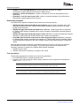
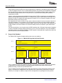
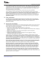

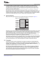
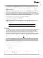
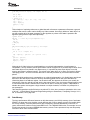

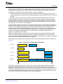
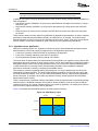
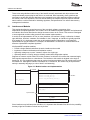
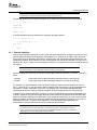
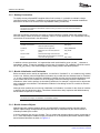
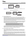
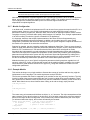

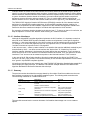
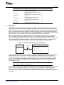
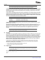
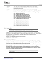
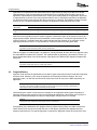

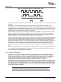
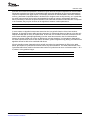

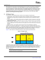
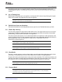

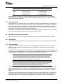

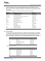

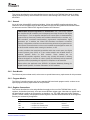
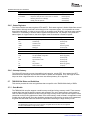

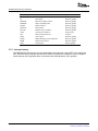
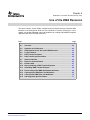
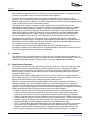
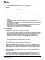
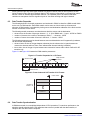
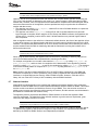
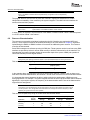
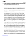
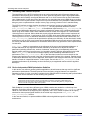
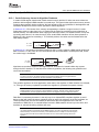
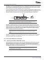
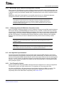
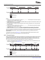
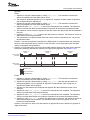


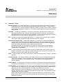
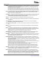
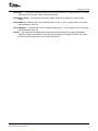
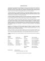


![manual [372769 bytes]](http://vs1.manualzilla.com/store/data/005891066_1-6553408cfa4c941a2bbbbb48a824c132-150x150.png)