1
RingMaster™
Monitoring and Management Guide
Release
7.4
1 February 2011 (Release Date)
Part Number: 730-9502-0232, Revision C
Copyright © 2011, Juniper Networks, Inc.
Juniper Network, Inc.
1194 N. Mathilda Avenue
Sunnyvale, CA 94089
USA
408-745-2000
www.juniper.net
ii
Copyright © 2011, Juniper Networks, Inc.
About This Guide
RingMaster 7.4 Management Guide
This guide is part of a Publications Suite intended for network administrators or persons responsible
for installing and managing a Wireless Local Area Network (WLAN) using RingMaster software. It
provides detailed procedures for managing a Wireless Local Area Network (WLAN) using RingMaster
software. As described in detail in the RingMaster Quick Start Guide, you install RingMaster
Services and RingMaster Client software on selected hosts. You start using RingMaster Services
(as described below) on a host and a RingMaster Client on the same or a different host to begin
management of your WLAN.
RingMaster Publication Suite
The following documents provide information on how to install RingMaster software and then use it
to plan, configure, and manage a WLAN.
Publications that make up the RingMaster Publication Suite are:
❑
RingMaster Quick Start Guide — This guide provides a description of prerequisites and
procedures required to install and begin using RingMaster software. Information is provided
about system requirements for optimum performance, as well as how to install RingMaster
Client and RingMaster Services software.
❑
RingMaster 7.1 Planning Guide— This guide provides instructions for planning a WLAN with
the RingMaster tool suite.It describes RingMaster planning tools. It is intended for network
administrators or persons responsible for planning a WLAN using RingMaster software.
❑
RingMaster 7.1 Configuration Guide — This guide provides instructions for configuring a WLAN
with the RingMaster tool suite. It describes RingMaster WLAN configuration tools. It is
intended for administrators or persons responsible for configuring a WLAN using RingMaster
software.
❑
RingMaster 7.1 Management Guide (this document) — This guide is described above.
Mobility System Configuration and Management
RingMaster is used with Trapeze Mobility System hardware and software, as described in the
following publications:
❑
Trapeze Mobility System Software Configuration Guide — This guide provides instructions for
configuring and managing a system using the Trapeze Mobility System Software (MSS)
Command Line Interface (CLI).
❑
Trapeze Mobility System Software Command Reference — This publication provides functional
and alphabetic reference to all MSS commands supported on MXs and MPs
❑
Trapeze Mobility Exchange Hardware Installation Guide — Instructions and specifications for
installing an MX.
❑
Trapeze Mobility System Software Quick Start Guide — Instructions for performing setup of
secure (802.1X) and guest (WebAAA™) access, and configuring a Mobility Domain for roaming
❑
Trapeze Mobility Point MP-422 Installation Guide — Instructions and specifications for installing
an MP access point and connecting it to an MX.
❑
Trapeze Mobility Point MP-620 Installation Guide — Instructions and specifications for installing
the MP-620 access point and connecting it to an MX.
❑
Trapeze Regulatory Information — Important safety instructions and compliance information
that you must read before installing Trapeze Networks products
Documentation Conventions
This section describes documentation conventions used by various RingMaster publications.
Copyright © 2011, Juniper Networks, Inc.
i
Safety and Advisory Notices
The following types of safety and advisory notices appear in this guide.
This situation or condition can lead to data loss or damage to the product or
other property.
This is a process or procedural tip or other useful suggestion.
Tip
This information you should note relevant to the current topic.
This alerts you to a possible risk of personal injury or major equipment problems.
Hypertext Links
Hypertext links appear in Blue.
As an example, this is a link to Contacting the Technical Assistance Center.
Illustration Formats
RingMaster software presents a Graphical User Interface (GUI) to its users, consisting of a series of
screens, windows, and dialog boxes. In many cases, sample images of these GUI elements have
been included in this publication. The RingMaster GUI allows you to resize these elements, and this
has been done to minimize element illustration sizes in this publication, while retaining all of the
information visible in them. This resizing of screens, windows and dialog results in illustrations that
may differ in appearance from what you may see on your workstation display.
Whenever possible, RingMaster screens, windows and dialog boxes are shown in their entirety, with
consistent relative sizes, except where large sizes precludes this, then they are shown as large as
possible. In addition to overall screen, window and dialog box resizing, you can adjust columns in
tables, etc. to change their appearance. To change these items, move your cursor over a border,
column separator, etc. and you will see a “resize” indication (a double ended arrow).
Text and Syntax Conventions
Trapeze guides use the following text and syntax conventions:
ii
Convention
Use
Monospace text
Sets off command syntax or sample commands and system responses.
Bold text
Highlights commands that you enter or items you select.
Italic text
Designates command variables that you replace with appropriate values
or highlights publication titles or words requiring special emphasis.
Copyright © 2011, Juniper Networks, Inc.
Convention
Use
Bold italic text font
Bold italic text font in narrative, capitalized or not, indicates a program
name, function name, or string.
Menu Name > Command Indicates a menu item. For example, File > Exit indicates that you select
Exit from the File menu.
[ ] (square brackets)
Enclose optional parameters in command syntax.
{ } (curly brackets)
Enclose mandatory parameters in command syntax.
| (vertical bar)
Separates mutually exclusive options in command syntax.
For information about Juniper support services, visit
http://www.trapezenetworks.com/supportportal/,
or call 1-866-877-9822 (in the US or Canada) or +1 925-474-2400 and select option 5.
Juniper Networks sells and services its products primarily through its authorized resellers and
distributors. If you purchased your product from an authorized Trapeze reseller or distributor and
do not have a service contract with Trapeze Networks, you must contact your local reseller or
distributor for technical assistance.
Contacting the Technical Assistance Center
Contact the Juniper Networks Technical Assistance Center (TAC) by telephone, email, or via web
support portal.
❑
Within the US and Canada, call 1-866-TRPZTAC (1-866-877-9822).
❑
Within Europe, call +31 35 64 78 193.
❑
From locations outside the US and Canada, call +1 925-474-2400.
❑
In non-emergencies, send email to [email protected]
❑
If you have a service contract or are a Trapeze Authorized Partner, log in to http://
www.trapezenetworks.com/support portal/ to create a ticket online.
TAC Response Time
TAC responds to service requests as follows:
Contact method
Telephone
Email
Priority
Response time
Emergency
One hour
Non-emergency
Next business day
Non-emergency
Next business day
Information Required When Requesting Service
To expedite your service request, please have the following information available when you call or
write to TAC for technical assistance:
❑
Your company name and address
❑
Your name, phone number, cell phone or pager number, and email address
❑
Name, model, and serial number of the product(s) requiring service
❑
Software version(s) and release number(s)
❑
Output of the show tech-support command
❑
Wireless client information
❑
License levels for RingMasterTM and Mobility ExchangeTM (MX™) products
Copyright © 2011, Juniper Networks, Inc.
iii
❑
Description of any problems and status of any troubleshooting effort
Main Menu “Report Problem” Tool
You can click Help from the Main menu bar to access online help and to send a report to Trapeze TAC
electronically:
1. Select Help > Help to display HTML help about configuring and using RingMaster.
Select Help > Report Problem to report a problem to Trapeze Technical Support. This dialog
allow you to report problems to Trapeze Networks by filling in particulars and then clicking
Send Now to compose and send an email to Trapeze.
Warranty and Software Licenses
Current Trapeze Networks warranty and software licenses are available at
http://www.trapezenetworks.com/support/warranty.
Limited Warranty for Hardware and Software
TERMS AND CONDITIONS OF SALE
1. Software
Any software provided is licensed pursuant to the terms of Trapeze Networks' Software
License Agreement, an electronic copy of which is provided with the Software and a printed
copy of which is available upon request. The terms and conditions of the Software License
iv
Copyright © 2011, Juniper Networks, Inc.
2.
3.
4.
5.
6.
Agreement are incorporated herein in its entirety in this Terms and Conditions of Sale (“Terms
and Conditions of Sale”) by this reference. The terms of the Software License Agreement
control, except for the limited warranty set forth below (“Limited Warranty”).
Limited Hardware Warranty
Trapeze Networks, Inc. (“Trapeze Networks” or “Trapeze”) warrants to Customer, subject to
the limitation and disclaimer below, that all Trapeze hardware will be free from defects in
material and workmanship under normal use as follows: (a) if the hardware was purchased
directly from Trapeze Networks, for a period of one (1) year after original shipment by Trapeze
Networks to Customer or (b) if the hardware was purchased from a Trapeze Networks
Authorized Reseller, for a period of one (1) year from the date of delivery to Customer, but in
no event more than fifteen (15) months after the original shipment date by Trapeze (“Limited
Hardware Warranty”).
The date of original shipment from Trapeze Networks will be determined by shipping evidence
on file at Trapeze Networks. This Limited Hardware Warranty extends only to the Customer
who was the original purchaser of the hardware and may not be transferred to any subsequent
repurchasing entity. During the Limited Hardware Warranty period upon proper notice to
Trapeze Networks by Customer, Trapeze Networks will, at its sole option, either:
❍ Repair and return of the defective hardware;
❍ Replace the defective hardware with a new or refurbished component;
❍ Replace the defective hardware with a different but similar component that
contains compatible features and functions; or
❍ Refund the original purchase price upon presentation of proof of purchase to
Trapeze Networks.
Restrictions on the Limited Hardware Warranty.
This Limited Warranty does not apply if hardware (a) is altered from its original specifications,
(b) is installed, configured, implemented or operated in any way that is contrary to its
documentation, (c) has damage resulting from negligence, accident, or environmental stress,
(d) was subject to unauthorized repair or modification or (e) is provided to Customer for
pre-production, evaluation or charitable purposes.
Limited Software Warranty
Trapeze Networks warrants to Customer, subject to the limitation and disclaimer below, that
the software will substantially conform to its published specifications as follows: (a) if the
software was purchased directly from Trapeze Networks, for a period of ninety (90) days after
original shipment by Trapeze Networks to Customer or (b) if the software was purchased from
a Trapeze Networks Authorized Reseller, for a period of ninety (90) days from the date of
delivery to Customer commencing not more than ninety (90) days after original shipment date
by Trapeze), (“Limited Hardware Warranty”). The date of original shipment from Trapeze
Networks will be determined by shipping evidence on file at Trapeze Networks. This Limited
Software Warranty extends only to the Customer of original purchaser of the software and may
not be transferred to any subsequent repurchasing entity.
During the Limited Software Warranty period upon proper notice to Trapeze Networks by
Customer, Trapeze Networks will, at its option, either:
❍ Use reasonable commercial efforts to attempt to correct or provide workarounds
for errors;
❍ Replace the software with functionally equivalent software; or
❍ Refund to Customer the license fees paid by Customer for the software.
Trapeze Networks does not warrant or represent that the software is error free or that the
software will operate without problems or disruptions. Additionally, and due to the steady and
ever-improving development of various attack and intrusion technologies, Trapeze Networks
does not warrant or represent that any networks, systems or software provided by Trapeze
Networks will be free of all possible methods of access, attack or intrusion.
Restrictions on the Limited Software Warranty
This Limited Software Warranty does not apply if software (a) is altered in any way from its
specifications, (b) is installed, configured, implemented or operated in any way that is contrary
to its documentation, (c) has damage resulting from negligence, accident, or environmental
stress, (d) was subject to unauthorized repair or modification, or (e) is provided to Customer for
pre-production, evaluation or charitable purposes.
General Warranty Disclaimer
Copyright © 2011, Juniper Networks, Inc.
v
EXCEPT AS SPECIFIED IN THIS LIMITED WARRANTY, ALL EXPRESS OR IMPLIED
CONDITIONS, REPRESENTATIONS, AND WARRANTIES INCLUDING, WITHOUT
LIMITATION, ANY IMPLIED WARRANTY OR CONDITION OF MERCHANTABILITY,
FITNESS FOR A PARTICULAR APPLICATION OR PURPOSE, NONINFRINGEMENT,
SATISFACTORY QUALITY OR ARISING FROM A COURSE OF DEALING, LAW, USAGE,
OR TRADE PRACTICE, ARE HEREBY EXCLUDED TO THE EXTENT ALLOWED BY
APPLICABLE LAW. TO THE EXTENT AN IMPLIED WARRANTY CANNOT BE EXCLUDED,
SUCH WARRANTY IS LIMITED IN DURATION TO THE AFOREMENTIONED WARRANTY
PERIOD. BECAUSE SOME STATES, COUNTRIES OR JURISDICTIONS DO NOT ALLOW
LIMITATIONS ON HOW LONG AN IMPLIED WARRANTY LASTS, THE ABOVE LIMITATION
MAY NOT APPLY. THIS LIMITED WARRANTY GIVES YOU SPECIFIC LEGAL RIGHTS, AND
YOU MAY ALSO HAVE OTHER RIGHTS, WHICH VARY FROM JURISDICTION TO
JURISDICTION. THE LIMITED WARRANTY ABOVE IS THE SOLE REMEDY FOR ANY
BREACH OF ANY WARRANTY WITH RESPECT TO THE HARDWARE AND SOFTWARE
AND IS IN LIEU OF ANY AND ALL OTHER REMEDIES.
7. Limitation of Liabilities
IN NO EVENT SHALL TRAPEZE NETWORKS, ITS SUPPLIERS, OR ITS AUTHORIZED
RESELLERS BE LIABLE TO CUSTOMER OR ANY THIRD PARTY FOR ANY LOST
REVENUE, PROFIT, OR DATA, OR FOR SPECIAL, INDIRECT, CONSEQUENTIAL,
INCIDENTAL, OR PUNITIVE DAMAGES REGARDLESS OF HOW THOSE DAMAGES
WERE CAUSED. NOR WILL TRAPEZE NETWORKS, ITS SUPPLIERS, OR ITS
AUTHORIZED RESELLERS BE LIABLE FOR ANY MONETARY OR PUNITIVE DAMAGES
ARISING OUT OF THE USE OF, OR INABILITY TO USE TRAPEZE NETWORKS
HARDWARE OR SOFTWARE. TRAPEZE NETWORKS' LIABILITY SHALL NOT EXCEED
THE PRICE PAID BY THE CUSTOMER FOR ANY HARDWARE OR SOFTWARE COVERED
UNDER THE TERMS AND CONDITIONS OF THIS WARRANTY.
THIS LIMITATION OF LIABILITY AND RESTRICTION ON DAMAGES APPLIES WHETHER
IN CONTRACT, TORT, NEGLIGENCE, OR OTHERWISE, AND SHALL APPLY EVEN IF THE
LIMITED WARRANTY FAILS OF ITS ESSENTIAL PURPOSE. WARRANTY LAWS VARY
FROM JURISDICTION TO JURISDICTION, AND THE ABOVE LIMITATIONS AND
EXCLUSION OF CONSEQUENTIAL AND INCIDENTAL DAMAGES MAY NOT APPLY TO
YOU, DEPENDING UPON YOUR STATE, COUNTRY OR JURISDICTION.
8. Procedures for Return of Hardware or Software under the Limited Warranty
Where repair or replacement is required under the Limited Warranty, Customer will contact
Trapeze Networks and obtain a Return Materials Authorization number (“RMA Number”) prior
to returning any hardware and/or software, and will include the Trapeze Networks RMA
Number on all packaging. Trapeze Networks will ship repaired or replacement components
within a commercially reasonable time after receipt of any hardware and/or software returned
for the Limited Warranty purposes to the address provided by Customer. Customer will pay
freight and handling charges for defective return to the address specified by Trapeze Networks
and Trapeze Networks will pay freight and handling charges for return of the repair or
replacement materials to Customer.
9. Miscellaneous
The Limited Warranty shall be governed by and construed in accordance with the laws of the
State of California without reference to that State's conflict of laws rules and as if the contract
was wholly formed within the State of California. Customer agrees that jurisdiction and venue
shall be in Santa Clara County, California. Under no circumstances shall the United Nations
Convention on the International Sale of Goods be considered for redress of grievances or
adjudication of any warranty disputes that include Trapeze Networks hardware or software. If
any provision of these Terms and Conditions of Sale are held invalid, then the remainder of
these Terms and Conditions of Sale will continue in full force and effect. Where a Customer
has entered into a signed contractual agreement with Trapeze Networks for supply of
hardware, software or services, the terms of that agreement shall supersede any terms
contained within this Limited Warranty. Customer understands and acknowledges that the
terms of this Limited Warranty, as well as material information regarding the form, function,
operation and limitations of Trapeze Networks hardware and software will change from time to
time, and that the most current revisions will be publicly available at the Trapeze Networks
corporate web site (www.trapezenetworks.com).
vi
Copyright © 2011, Juniper Networks, Inc.
1
RingMaster Services
This chapter describes the use of RingMaster Services software.
Starting or Stopping RingMaster Services
The method for starting and stopping RingMaster Services depends on the platform on which the
service is installed:
❑
Windows systems — RingMaster Services are started automatically when you complete
installation and start automatically whenever you restart your system.
❑
Linux systems — You can start and stop these services manually from the command line using
a shell script installed when you install RingMaster Services. You can configure services to
start and stop automatically.
❑
Macintosh systems — RingMaster Services are not started automatically — you must start
them manually.
All clients using RingMaster Services should be closed before you stop services. If a RingMaster
Client is using a network plan on RingMaster Services when you stop the services, you cannot select
objects or options in the client. In this case, to close the client, click the X in the upper right corner of the
window or use Task Manager to end the client session.
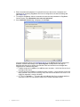
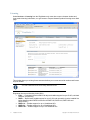
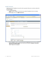
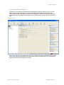
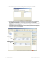
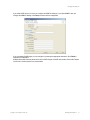
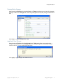
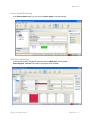
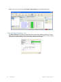
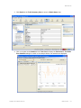
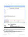
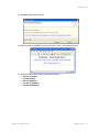
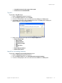
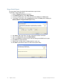
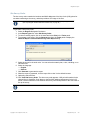
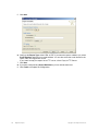
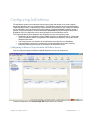
Windows Systems
You can start RingMaster Services on a Windows system from within RingMaster or from Windows
Services.
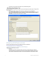
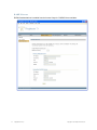
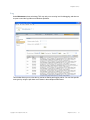
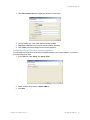
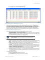
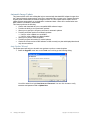
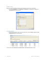
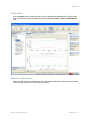
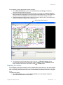
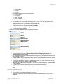
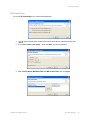
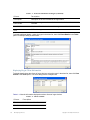
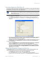
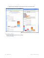
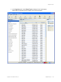
1. Display the Services window. Here is an example of the Services window in Windows.
This is located in Control Panel > Administrative Tools > Services. (The window might look
different on your system.)
2. Scroll down and select RingMaster Services.
1.
Copyright © 2011, Juniper Networks, Inc.
RingMaster Services
1
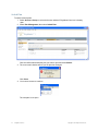
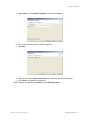
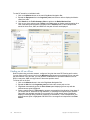
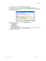
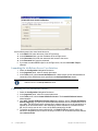
3. Select the Start or Stop item in the Action menu item.
4. Close the Services window.
5. Within RingMaster, enable it to access the service. (See Connecting a Client to RingMaster
Services.)
Linux Systems
To start RingMaster Services manually on a Linux system, as the root user, type:
prompt# rm-services start
To stop RingMaster Services manually, type:
prompt# rm-services stop
These examples assume RingMaster Services are installed in the default location.
Macintosh Systems
To start RingMaster Services manually on a Macintosh system, open a Terminal window, either by
using the shortcut on the dock, or by browsing to /Applications/Utilities and launching Terminal from
there. In the Terminal window, change to the bin directory in the RingMaster installation directory. By
default, this is /Applications/RingMaster/bin.
For example:
# cd /Applications/RingMaster/bin
To start RingMaster Services, enter:
# sudo ./rm-services start
Enter the password, if prompted.
To stop or restart RingMaster Services, enter:
# sudo ./rm-services stop
# sudo ./rm-services restart
Either of these commands may require you to enter a password. These examples assume that
RingMaster Services is installed in the default location.
Configuring a Daemon on SUSE 9.1
To add services to a SUSE 9.1 installation, use the insserv command.
Enter the following commands (as root):
suse# cd /etc/init.d
suse# ln -s /opt/ringmaster/bin/rm-services rm-services
suse# insserv rm-services
Configuring a Daemon on Red Hat WS 3
To add services to a Red Hat WS 3 system, use the chkconfig command.
Enter the following (as root):
redhat# cd /etc/init.d
redhat# ln -s /opt/ringmaster/bin/rm-services rm-services
redhat# chkconfig --add rm-services
2
RingMaster Services
Copyright © 2011, Juniper Networks, Inc.
RingMaster Services
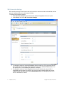
Connecting a Client to RingMaster Services
If a firewall is enabled on the host where you install RingMaster Services, RingMaster Services will
not be able to communicate with RingMaster Clients or with MXs unless the firewall is configured to
allow through traffic for the SSL and SNMP ports (443 and 162 by default).
To connect to RingMaster Services:
1. Start RingMaster Client. Do one of the following:
❑
On Windows systems, select Start > Programs > Trapeze Networks > RingMaster >
RingMaster, or double-click the RingMaster icon on the desktop.
❑
On Linux systems, change directories to RingMaster_installation_directory/bin, and
enter ./ringmaster.
❑
On Macintosh systems, select Finder > Applications > RingMaster, or click the
RingMaster icon in the dock.
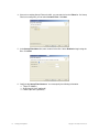
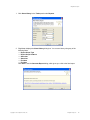
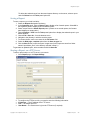
The RingMaster Services Connection dialog appears.
2. Enter the IP address or fully-qualified hostname of the server on which the service is installed
(if not pre-filled). If the service is installed on the same server as the one you are using to run
RingMaster, enter 127.0.0.1 as the IP address. This is a standard IP loopback address.
3. Specify the service port, if different from the port number in the Port selector list.
The port number used by RingMaster Services must not be used by another application on the
server where RingMaster Services is installed. If the port number is used by another application,
change the port number on RingMaster Services. (See Setup Tab.)
Copyright © 2011, Juniper Networks, Inc.
RingMaster Services
3
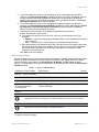
4. Enter a username and password, if required for access to the service. Usernames and
passwords for accessing RingMaster Services are configured on the Service Settings tab.
(See Setup Tab.)
5. To configure RingMaster Client to remember the username and password for RingMaster
Service access, select Remember user name and password.
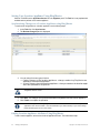
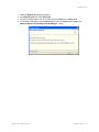
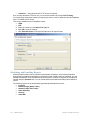
6. If the Certificate Check dialog is displayed, click Accept.
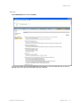
(For more certificate options, see Certificate Check.) If the Finish button does not become
available, read the last message in the Open Progress message area of the page to
determine why the service could not be reached. Here are common error messages and
suggestions for troubleshooting them:
❍ Unable to connect to address: ip-addr:tcp-port-number— Verify that the service is
running on the server.
❍ Connection error for address: ip-addr:tcp-port-number — Verify that the service has
been started. If the service is running, verify that the certificate on the server is still
valid (for example, is not out of date).
❍ HTTP 403: Forbidden — This message can indicate that the username and password are invalid. Ask the administrator for a username and password.
4
RingMaster Services
Copyright © 2011, Juniper Networks, Inc.
RingMaster Services
Certificate Check
If a License message appears, go to “Licensing” in the publication RingMaster Planning Guide.
When the RingMaster Client connects to RingMaster Services, it checks the certificate presented by
RingMaster Services to verify the certificate’s validity. The certificate is in a key store file on the
server. The default key store file is .rmservices_keystore. This file contains a self-signed certificate
for RingMaster Services. You can use this certificate or you can configure services to use a different
key store file containing a different certificate. (See Setup Tab.) By default, the RingMaster Client
does not accept self-signed certificates, even from RingMaster Services. Instead, when RingMaster
Services or another device presents a self-signed certificate to the RingMaster Client, the
Certificate Check dialog box appears on the client and displays the certificate information.
Options you select in this dialog box apply to all HTTPS connections with a RingMaster Client. For
example, the RingMaster Client also checks the validity of certificates presented by MXs, and the
settings you select in this dialog affect those connections too.
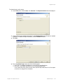
To complete the connection:
1. Select one or both of the following options, within 60 seconds after the Certificate Check
dialog is displayed:
❑
Always accept self-signed certificates — Use this option to configure the RingMaster
Client to always accept a self-signed certificate from the RingMaster monitoring service
and from MXs.
❑
Install this certificate to validate future connections — Use this option to accept the
certificate and consider the certificate to be valid for future connections.
When you use this option, the Certificate Check dialog box is not shown again for the certificate, even if
the certificate becomes out of date.
Copyright © 2011, Juniper Networks, Inc.
RingMaster Services
5
2. Click Accept. To reject the certificate and refuse the connection, click Reject. RingMaster
ends the connection.
If none of the checkboxes in Step 1 are checked, the Certificate Check dialog box is re-displayed each
time the RingMaster Client attempts to establish a connection with RingMaster Services.
3. A dialog is shown briefly as a RingMaster Services connection is established. Click Finish.
6
RingMaster Services
Copyright © 2011, Juniper Networks, Inc.
RingMaster Services
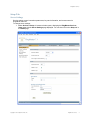
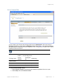
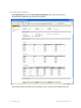
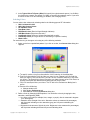
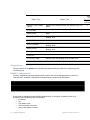
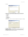
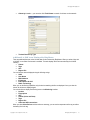
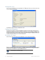
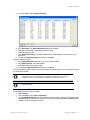
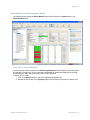
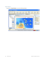
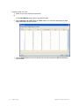
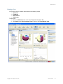
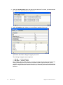
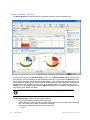
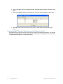
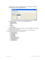
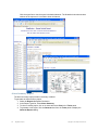
RingMaster Services Home Page
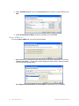
To change server settings:
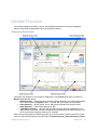
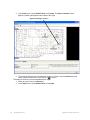
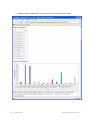
1. Select Services > Setup. A browser window opens, displaying the RingMaster Services
Setup page displayed. Click on Home and you see the following page.
The window above shows you information on the RingMaster Server and its performance, allows you
to Launch a Web Start Client, and provides status regarding Users on the server.
You can click on the tabs for Setup, Plan Management, Reports and Maintenance. Each of these is
described in paragraphs below.
Copyright © 2011, Juniper Networks, Inc.
RingMaster Services
7
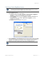
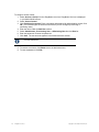
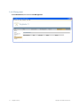
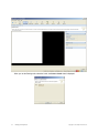
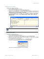
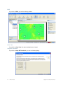
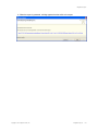
Web Start Client
If you click Launch Client, a RingMaster Web Start Client will be installed on your workstation. You
will see a Java startup image, followed by the dialog below:
If this fails, click on the link provided to install JRE 6.0.
You then see the RingMaster Services connection dialog shown below:
Select or enter the address of the RingMaster Server you wish to connect to and continue normally.
8
RingMaster Services
Copyright © 2011, Juniper Networks, Inc.
RingMaster Services
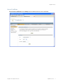
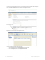
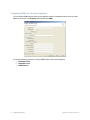
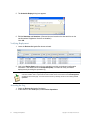
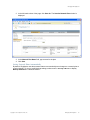
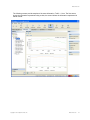
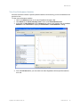
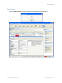
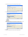
Setup Tab
Server Settings
Service settings control connection parameters, key store information, and access control to
RingMaster Services.
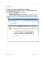
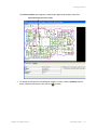
To change server settings:
1. Select Services > Setup. A browser window opens, displaying the RingMaster Services
Setup page with the Server Settings page displayed. You can also click on the Setup tab in
the Home page.
Copyright © 2011, Juniper Networks, Inc.
RingMaster Services
9
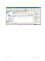
The port numbers used by RingMaster Services must not be used by other applications on the
server where RingMaster Services is installed. If port 443 or 162 is used by another application,
change the port number for RingMaster Services or for the other application.
You can only access this page to change RingMaster port 443 if it was able to get this port. If another
application is running, RingMaster Services cannot display this web page. services-conf.xml must
be edited manually or you must call TAC.
2. To change the TCP port on which RingMaster Services listens for requests from RingMaster,
type or select the port number in the HTTPS Server Port field.
The default is 443.
When you click Save, all instances of the RingMaster Client lose connection with the
service and must re-connect on the new port number. The HTTPS port number is
automatically updated for the RingMaster Client and connection is restored. Other
clients must use the Monitor Service Select wizard to change the service port and
reconnect.
3. To enable RingMaster to re-use an MX configuration to replace an old MX with a new one,
select Auto-Config IP Subnet Matching. (For more information about this option, see
“Replacing an MX and Reusing the Configuration” in the publication RingMaster
Configuration Guide.)
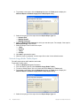
4. The change the UDP port on which RingMaster Services listens for SNMP traps, type or
select the port number in the Trap Receiver Port field. The default is 162.
5. To enable RingMaster Services to receive traps, select one or both of the following trap
types:
❑
SNMP V1 Traps
❑
SNMP V3 Traps
You also must add RingMaster Services as a notification target on each MX. RingMaster
Services does not start listening for SNMP notifications from an MX until you add RingMaster
Services as an SNMP notification target to the MX. (To configure RingMaster Services as a
notification target for an MX, see “Configuring RingMaster Services as a Notification Target” in the
publication RingMaster Configuration Guide.)
6. To change the name of the key store file that contains the encryption keys RingMaster
Services uses for authentication with RingMaster, edit the name in the File field. The default
name is .rmservices_keystore.
Caution must be used when editing this. If a change is unsuccessful, you will not be able to start
RingMaster Services. You will have to call TAC.
7. To change the password that protects access to the key store file, edit the value in the
Password field.
8. To specify the file type for the key store file, select one of the following:
❑
PKCS12 — Public-Key Cryptography Standard number 12.
❑
JKS — Java Key Store, a format used by Java platforms and applications.
10
RingMaster Services
Copyright © 2011, Juniper Networks, Inc.
RingMaster Services
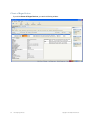
Server Certificate
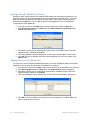
Select Server Certificate from the Setup browser window and view server certificates.
Copyright © 2011, Juniper Networks, Inc.
RingMaster Services
11
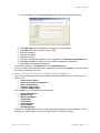
Licensing
Select Services > Licensing from the RingMaster main menu bar to open a browser window and
view product licensing information, or to get access to Trapeze Networks product licensing server Web
page.
This window shows you existing license status and allows you to enter new serial numbers and license
keys as needed.
You need a valid base license before adding additional licenses
Ringmaster has several licensing levels (SKU):
❑
EVAL — Evaluation license is valid for 90 days and enables support for up to 50 APs, unlimited
switches, and planning.
❑
RMTS — Base license enables support for up to 5 APs and one switch (must be installed first
before installing other RMTS licenses like the RMTS-50, RMTS-100, RMTS-500 and
RMTS-PLAN).
❑
RMTS-10 — Enables support for up to 10 additional APs.
❑
RMTS-50 — Enables support for up to 50 additional APs.
❑
RMTS-100 — Enables support for up to 100 additional APs.
12
RingMaster Services
Copyright © 2011, Juniper Networks, Inc.
RingMaster Services
❑
❑
❑
❑
❑
❑
❑
❑
❑
RMTS-250 — Enables support for up to 100 additional APs.
RMTS-500 — Enables support for up to 500 additional APs.
RMTS-1000 — Enables support for up to 1000 additional APs.
RMTS-PLAN — Enables planning.
RMTS-AGENT — Enables RM Agent.
SP-EVAL — SmartPass evaluation license is valid for 90 days and enables support for 50 user
accounts.
SP — Base license for SmartPass valid for 50 user accounts
SP-ENT — Enterprise license for SmartPass valid for 10050 user accounts.
SP-ACC — Access license for the access control plug-in (with API), needs SP and
SP-ENT for activation.
Copyright © 2011, Juniper Networks, Inc.
RingMaster Services
13
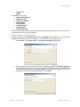
MX Connection Settings
MX connection settings control timeout and retry intervals for connections with monitored MXs, and the
types of certificates the service will accept from MXs.
To change MX connection settings:
1. Select Services > Setup or select the browser window if RingMaster Services is open.
2. Select Setup, then select MX Connection Settings.
3. To change the number of seconds RingMaster Services waits for a TCP connection with an
MX to reach the Connect stage, type or select the value in the Connect Timeout field. You
can specify from 1 to 30 seconds. The default is 5 seconds.
4. To change the number of times RingMaster Services will reattempt to query an MX, if
RingMaster Services does not receive a reply to the first query attempt within the connect
timeout, type or select the value in the Connect Retries field. You can specify from 0 to 5
retries. The default is 3 retries.
14
RingMaster Services
Copyright © 2011, Juniper Networks, Inc.
RingMaster Services
5. To prevent RingMaster Services from accepting all types of certificates from the MXs it
monitors, click Accept all certificates to disable the option. By default, RingMaster Services
accepts certificates from MXs regardless of whether they are generated by a certificate
authority (CA) or they are self-signed certificates. When you disable this option, the Accept
self-signed certificates option remains enabled.
6. To prevent RingMaster Services from accepting self-signed certificates from the MXs it
monitors, click Accept Self-signed certificates to disable the option. When both the Accept
all certificates and Accept Self-signed certificates options are disabled, RingMaster
Services accepts only CA generated certificates.
7. To specify a key store filename and a password to protect access to that file:
a. Enter the filename in the File field.
b. To change the file type for the key store file, select one of the following in the Type
pull-down:
◆ PKCS12 — Public-Key Cryptography Standard number 12, the standard format used by
Linux machines.
◆ JKS — Java Key Store, a format used by Java platforms and applications.
c. Enter the password in the Password field. When both the Accept all certificates and Accept
self-signed certificates options are disabled, and you specify a key store file, RingMaster
Services accepts a certificate from an MX only if the public key information for that
certificate is in the key store file.
Click Save to save the changes.
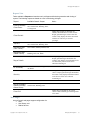
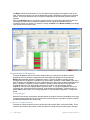
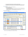
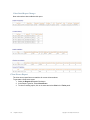
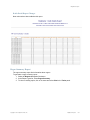
Monitoring Settings
By default, status monitoring and monitoring of MX notifications is enabled. Status monitoring supplies
data for the Explore and Status Summary windows of the Monitor tab. SNMP notifications (traps)
generated by MXs supply data for the Client Monitor, RF Monitor, and RF Trends windows.
Table 1– 1 lists the source of the data for each window in the Monitor button and for the Performance
Statistics window.
Table 1– 1. Sources of Monitor Data
RingMaster Client Display
Data Source
Default
Monitor — Status Summary
Status monitoring of MXs by RingMaster Services
Enabled
Monitor — Clients
Enable Client Session Collection option
Enabled
Monitor — Traffic
Radio and Port statistics.
Enabled
Monitor — High Utilization,
RF Interference, and
Coverage Hole
Enable Traffic & RF Trending option and configure RF
Threshold Settings
Enabled
Alarms
Input from all polls
Enabled
The monitoring options require SNMP traps to be enabled on the monitored MXs and also require
RingMaster Services to be configured as a notification target (trap receiver) for each of the MXs.
The data for some reports also requires monitoring options to be enabled. For information, see
descriptions for each report in Chapter 7 “RingMaster Reports”.
To change monitoring settings:
Copyright © 2011, Juniper Networks, Inc.
RingMaster Services
15
1. Select Services > Setup or select the browser window if RingMaster Services is already
open.
2. Select Setup, then select Monitoring Settings.
16
RingMaster Services
Copyright © 2011, Juniper Networks, Inc.
RingMaster Services
3. To change Polling Options, use click boxes to enable features and enter values you want for
enabled items, including:
❑
Auto-Adjust Poll Intervals — By default, Auto-Adjust Poll Interval is selected. If the
server detects the number of devices exceeding a certain limit, it will automatically adjust
the poll interval for all to a higher value. You will not be able to set a poll interval lower than
the recommended setting. If Auto-Adjust Poll Interval is not selected, you can change the
poll interval to any value between 5 and 60 minutes.
❑
Status
❑
Client Sessions
❑
Radio and Port Statistics
❑
Rogue Devices
❑
Configuration Changes
4. To make choices regarding the Radio and Port Statistics Database, make the following
selections:
❑
Average Specific Times in Rollup — Checkbox
❑
Include Days of week and Hours — This restricts data averaging for reports for higher
accuracy within specified hours/days.
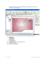
5. To change the RF Threshold Settings, enter new settings for the following statistics [default
settings are indicated in brackets]:
❑
Radio Retransmit Threshold (%) [10]
❑
Radio Noise Floor Threshold (dBm) [-85]
❑
Radio Signal Level Threshold (dBm) [-75]
❑
Utilization Threshold (%) [80]
❑
SNR Threshold (dBm) [15]
❑
Number of Clients per Radio [15]
You can click Reset Threshold Settings to revert to default values.
Click Save to save changes.
Copyright © 2011, Juniper Networks, Inc.
RingMaster Services
17
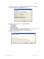
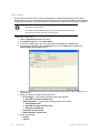
SNMP Notification
SNMP traps that the RingMaster Server will be able to generate will be sent to receivers configured in
the RM Web page.
To set up SNMP notifications:
1. Select Services > Setup or select the browser window if RingMaster Services is already
open.
2. Select Setup, then select SNMP Notification.
3. Enter a Target IP, accept or change the Port aned Community entries and select a versio of
SNMP from the Version pull-down. Use check boxes to determine Category and Severity
filter settings and then click Add.
SNMP Targets will be displayed.
18
RingMaster Services
Copyright © 2011, Juniper Networks, Inc.
RingMaster Services
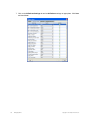
Access Control Tab
You can create a user account with privileges either as a full Administrator, allow users to have
Provision capabilities, or allow them only Monitor privileges. See Table 1– 2 for privilege definitions.
For details, refer to “Restricting Access to RingMaster” in the “Getting Started” chapter of the Trapeze
RingMaster Reference Manual.
You must add a user first if none are defined before enabling access control.
Table 1– 2. User Privilege Levels
Privilege Level
Access
Control
Configurati
on
Monitoring
Administrator
yes
yes
yes
Provision
no
yes
yes
Monitor
no
no
yes
To change Access Control settings:
1. Select Services > Setup or select the browser window if RingMaster Services is open.
2. Select Setup, then select Access Control.
Copyright © 2011, Juniper Networks, Inc.
RingMaster Services
19
To configure access control:
1. Select Services > Setup from the RingMaster menu bar. RingMaster Services is displayed
in your default Web browser.
2. Select Access Control.
3. Click Enable login-required. Enter a username and password for administrative access. Click
OK. (You must configure an admin account before you can configure provisioning or
monitoring users.)
4. Enter the name under the Add User section.
5. Select Administrator, Provisioning User, or Monitoring User form the Role list.
6. Enter the password. Re-enter the password.
7. Click Save. The new account appears in the Authorized Users section.
The RingMaster Services Home Page lists authorized users, their roles and
connection status/times
8. To remove an account, click Delete next to the desired account.
9. To reset a password, click Edit.
20
RingMaster Services
Copyright © 2011, Juniper Networks, Inc.
RingMaster Services
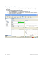
User Groups
User Groups are created in the Add User Group section of the Setup > Access Control page for
configuring view restriction rules for Monitoring Users. View restriction rules are configured only for the
current plan. These rules are not applied when switching to a different plan.
The following new fields are added to the Add User section of the Setup Access Control page as
well as the Edit User Info popup window.
These fields are enabled when Monitoring Users are specified:
❑
A check box for view restriction.
❑
Scope Type Combo box that allows a user to select a restriction scope type. Site and Building
are the only two supported scope types in the 7.0 release.
❑
Scope Instance Combo box that shows all the related instances of the selected scope type.
The following is a screen shot showing the Access Control > User Groups window containing these
new fields:
Copyright © 2011, Juniper Networks, Inc.
RingMaster Services
21
RADIUS Servers
RADIUS authentications is enabled from the Access Conytrol > RADIUS Servers window.
22
RingMaster Services
Copyright © 2011, Juniper Networks, Inc.
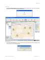
RingMaster Services
Plan Management Tab
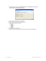
New Plan
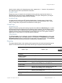
To set up a new network plan:
1. Select Services > Setup or select the browser window if RingMaster Services is already
open.
2. Select Plan Management, then select New Plan.
Enter a new Network Plan Name, select a Country Code, select Open This Plan? and click
Create.
Copyright © 2011, Juniper Networks, Inc.
RingMaster Services
23
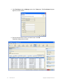
Switch Plan
To switch network plans:
1. Select Services > Setup or select the browser window if RingMaster Services is already
open.
2. Select Plan Management, then select Switch Plan.
Click the radio button beside the plan you wish to open and select Switch.
3. The current main window will tell you the plan has changed:
Click Close.
4. You must re-connect to continue.
The new plan is now open.
24
RingMaster Services
Copyright © 2011, Juniper Networks, Inc.
RingMaster Services
Delete Plans
To delete network plans:
1. Select Services > Setup or select the browser window if RingMaster Services is already
open.
2. Select Plan Management, then select Delete Plans.
Click the check boxes beside plans you wish to delete and select Delete.
Import Plan
To import network plans:
1. Select Services > Setup or select the browser window if RingMaster Services is already
open.
2. Select Plan Management, then select Import Plan.
Select the plan you wish to import from the pull-down menu.
Copyright © 2011, Juniper Networks, Inc.
RingMaster Services
25
Save As
To import network plans:
1. Select Services > Setup or select the browser window if RingMaster Services is already
open.
2. Select Plan Management, then select Save As.
Enter a new plan name and click Save.
26
RingMaster Services
Copyright © 2011, Juniper Networks, Inc.
RingMaster Services
Backup and Restore
RingMaster Services regularly back up network plans at configurable intervals. In addition to regular
backups, you can create a backup at any time. You can create a backup from within RingMaster or at
a command line. From within RingMaster, you change settings for automatic backups. To manage
backups, select Services > Backup & Restore. If RingMaster Services is already open in the
browser window, select Plan Management, then select Backup & Restore.
Existing backups for network plans are listed. Backups automatically created by RingMaster do not
have names, and their type is Automatic. Backups you create have names, and their type is Manual.
Only backups for the currently open plan are listed. By default, backups created automatically by
RingMaster are stored in the following location:
RingMaster\backup\auto\plan_name
Backups created by you are stored in the following location by default:
RingMaster\backup\manual\plan_name
RingMaster zips backup files and assigns them unique names. You can assign a name to a backup
that you create. However, this name does not appear in the backup directory. To select a plan based
on a name you assign, use the Backup/Restore dialog.
Backing Up a Plan
To immediately create a backup:
1. Select Services > Backup & Restore. If RingMaster Services is already open in the browser
window, select Plan Management, then select Backup & Restore.
2. Type a name for the backup in the Backup Name field.
3. Click Create Backup. When the backup is complete, it appears in the list of backups. (If you
do not see the backup, scroll to the bottom of the list.)
Copyright © 2011, Juniper Networks, Inc.
RingMaster Services
27
Changing Backup Settings
To change settings for automatic backups:
1. Select Services > Backup & Restore. If RingMaster Services is already open in the browser
window, select Plan Management, then select Backup & Restore.
2. To change how often RingMaster automatically backs up network plans, select Hourly or
Daily from the Backup Interval pull-down list.
3. If you select Daily, specify the time to create the backup.
4. To change the maximum number of backup copies RingMaster will keep for a plan, change the
number in the Number of backup copies field. Click Save.
Restoring a Plan from a Backup
To restore a plan from a backup:
1. Select Services > Backup & Restore. If RingMaster Services is already open in the browser
window, select Plan Management, then select Backup & Restore.
2. Select the backup you want to restore. Click Restore.
Copying a Plan Backup from One Server to Another
Copy a plan to another server by copying the backup file for that plan to the other server, and then
restoring the plan on the other server from the backup.
To copy a network plan backup from one server to another:
1. Select Services > Backup & Restore. If RingMaster Services is already open in the browser
window, select Plan Management, then select Backup & Restore.
2. Select the backup you want to restore. Click Transfer. The Transfer Backup dialog appears.
3. Type the IP address of the host where another instance of RingMaster Services is installed.
RingMaster Services must be running on the host where you want the backup
transferred to.
4. If the port on which the other instance of RingMaster Services listens for traffic from
RingMaster is different from the default, edit the number in the Service Port field to match.
5. Type the username and password required by the other instance of RingMaster Services.
Click Transfer.
6. On the server to which you copied the backup, access the Backup/Restore page.
7. Select the backup and click Restore.
28
RingMaster Services
Copyright © 2011, Juniper Networks, Inc.
RingMaster Services
Deleting a Plan Backup
To delete a plan backup:
1. Select Services > Backup & Restore. If RingMaster Services is already open in the browser
window, select Plan Management, then select Backup & Restore.
2. Select the backup and click Delete.
For more information on network plans, refer to the publication RingMaster
Planning Guide.
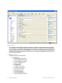
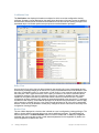
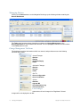
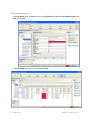
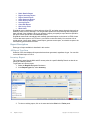
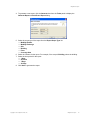
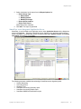
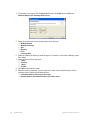
Reports Tab
This tab allows you to view, with and without filtering, and to delete reports.
The Filter by report type pull-down provides items by which reports can be filtered:
❑
All
❑
RF Summary
❑
Inventory
❑
Radio Details
❑
Mobile Domain Configuration
❑
Rogue Details
❑
Client Summary
❑
Rogue Summary
❑
Client Details
❑
Alarm Summary
❑
Client Errors
❑
Alarm History
❑
Wireless Network Usage (Radio Traffic)
❑
Security
❑
Wireless Network Usage (Port Traffic)
❑
Client OUI
Select reports using radio buttons adjacent report entries. There is a Reload button provided.
Copyright © 2011, Juniper Networks, Inc.
RingMaster Services
29
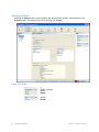
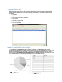
Maintenance Tab
Maintenance pages let you make a of settings, described in the following paragraphs.
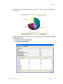
Memory
To access memory settings:
1. Select Services > Setup, if RingMaster Services is not displayed in a browser window.
2. Select Maintenance, then select Memory.
This screen shows Server Memory Used, Allocated, and Maximum, and provides a button to
force Java memory recovery.
30
RingMaster Services
Copyright © 2011, Juniper Networks, Inc.
RingMaster Services
Alarms
Select Maintenance, then select Alarms.
This window shows Server Performance Alarms and Alarm Statistics for the server.
Copyright © 2011, Juniper Networks, Inc.
RingMaster Services
31
Device Requests Statistics
Select Maintenance, then select Device Requests Statistics. This is used to assist TAC in
troubleshooting RingMaster server performance problems
This window provides information on server threads, queues, executing and completed items, etc.
32
RingMaster Services
Copyright © 2011, Juniper Networks, Inc.
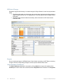
RingMaster Services
Log
Select Maintenance, then select Log. TAC may ask you to set a log level for debugging, and then run
a report or send the log folder to troubleshoot problems.
This window allows you to review the log, and to set filtering and logging values. You can view specific
error types by using the pull-down menu shown in the example window above.
Copyright © 2011, Juniper Networks, Inc.
RingMaster Services
33
Lock Management
Select Maintenance, then select Lock Management.
34
RingMaster Services
Copyright © 2011, Juniper Networks, Inc.
RingMaster Services
Threads
Select Maintenance, then select Threads.
This screen contains trouble shooting/debugging information on server threads that may be useful in
working with TAC on any server problems you may encounter.
Copyright © 2011, Juniper Networks, Inc.
RingMaster Services
35
36
RingMaster Services
Copyright © 2011, Juniper Networks, Inc.
RingMaster Client Preferences
This chapter describes how to change RingMaster Client preferences. You can set
RingMaster preferences for a user session on the system on which RingMaster is installed.
The preferences you set are valid only for that user on that system. Initial setting of RingMaster Client
preferences is described in detail in “Setting Preferences” in the publication RingMaster Planning
Guide. This chapter deals with updating and changing preferences.
Preferences Values
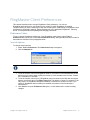
To set or change RingMaster preferences, in the RingMaster main window, select Tools >
Preferences and you will see a multi-tabbed Preferences dialog. Settings made with items on each of
these tabs are described in the paragraphs below.
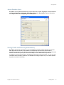
Network Options
To change network options:
1. Select Tools > Preferences. The Preferences dialog box appears.
2. Click the Network tab.
You can access these same settings as described above in MX Connection Settings.
3. To set the amount of time that RingMaster waits for a connection to be established to an MX
before trying to connect again, specify the timeout (1 to 30 seconds) in the Connect Timeout
box. The default is 5 seconds.
4. To set the number of times (0 to 5) RingMaster tries to reconnect to the MX after the original
attempt, specify the value in the Retry Count field. The default is 3 times. For example, if the
retry count is 3, RingMaster attempts to establish a connection to an MX four times. If you
specify 0, RingMaster does not attempt to establish a connection if the first attempt is
unsuccessful.
5. Click Close to close the Preferences dialog box, or click another tab to continue making
changes.
Copyright © 2011, Juniper Networks, Inc.
RingMaster Client Preferences
35
Tools Options
You can change the Telnet and Web browser applications that start from the RingMaster Tools menu.
The default Telnet application is Microsoft Telnet Client. The default Web browser is Microsoft Internet
Explorer.
To change tools options:
1. Select Tools > Preferences. The Preferences dialog box appears.
2. Click the Tools tab.
3. To change the Telnet executable file or location used by RingMaster, type the path of the
executable file in the Telnet Executable field. For Windows systems, the default Telnet
executable file is C:\WINDOWS\system32\telnet.exe. For Linux systems, the default is
/usr/bin/telnet. For Macintosh systems, the default is bin/sh telnet. You can also click
Browse to navigate a computer filesystem.
4. To change the Web browser executable file or location used by RingMaster, type the path of
the executable file in the Browser Executable field. For Windows systems, the default Web
browser executable file is C:\Program Files\Internet Explorer\iexplore.exe. For Linux
systems, the default is /usr/bin/mozilla. For Macintosh systems, the default is open. You can
also click Browse to navigate a computer filesystem.
5. Click Close to close the Preferences dialog box, or click another tab to make more changes.
RF Options
You can change the following RF planning options:
❑
Typical transmit power for clients in the Trapeze network.
❑
Color schemes for showing RF information
To change the transmit power of a typical client:
1. Select Tools > Preferences. The Preferences dialog box appears.
2. Click the RF tab.
36
RingMaster Client Preferences
Copyright © 2011, Juniper Networks, Inc.
RingMaster Client Preferences
3. In the Typical Client Tx Power (dBm) field, specify the typical transmit power (1 to 20 dBm)
for clients in the network. The default is 13 dBm, a common client transmit power. If you want
to choose a color for an RF technology or obstacle, see Changing Colors.
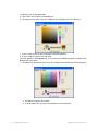
Selecting Colors
You can select color schemes by selecting tabs for the following types of RF information:
❑
802.11a Channel Colors
❑
802.11b/g Channel Colors
❑
RF Obstacle Colors
❑
Data Rate Colors
❑
RSSI Band Colors (Receive Signal Strength Indicator)
❑
SNR Band Colors (Signal-to-noise ratio)
❑
Load Band Colors (number of clients associated with a radio)
❑
Probability Colors (of a rogue device or client being in a specific location)
❑
Mesh Colors
For each scheme, you change a color using any of the following methods:
1. Select a color from a predefined palette. If you click on a color, the Choose Color dialog box
appears.
a. To specify a color using the color palette, click Swatches in the dialog box.
b. From the color palette, click the color you want to see. Repeat until you find the
color you want. In the Preview box, you can see the swatches and text in the color
you chose. The Recent box shows the colors you have chosen so far. Click Reset to
choose the original pre-defined color and clear the Recent field.
c. Click OK to accept colors you chose. The RF tab in the Preferences dialog box is
active.
d. Do one of the following:
◆ Change another color.
◆ Click another Preferences tab.
◆ Click Close to close the Preferences dialog box.
2. Define a Color by Changing HSB Properties. You can define colors by changing the hue,
saturation, and brightness (HSB).
❑
Hue is the color itself (for example, blue, orange, or purple). Hue is measured in degrees
(0 to 360 degrees).
❑
Saturation is the strength of the color. Saturation values are measured in percentages,
with 0 percent indicating no color saturation (gray) and 100 percent indicating full
saturation.
❑
Brightness is the amount of light in the color. Brightness is also measured in percentages,
with 0 percent indicating black and 100 percent indicating white.
Copyright © 2011, Juniper Networks, Inc.
RingMaster Client Preferences
37
To specify a color by changing HSB:
a. Click HSB in the Choose Color dialog box.
b. To change a hue value, click the H radio button and do one of the following.
c. In the H field, specify a value between 0 and 360 degrees.
d. Use the slider to specify the hue value.
The color appears in the Preview field. You can also see the RGB equivalent in the R, G, and
B fields next to the slider.
e. To change the saturation value, click the S radio button and do one of the following:
◆
◆
38
Use sliders to specify color values.
In the S selector box, specify a value between 0 and 100 percent.
RingMaster Client Preferences
Copyright © 2011, Juniper Networks, Inc.
RingMaster Client Preferences
f. To change the brightness value, click the B radio button and do one of the following
◆ In the B selector box, specify a value between 0 and 100 percent.
◆ Use the slider to specify a brightness value.:
g. Click OK to accept a color.
3. You can define a color by changing Red, Green, and Blue (RGB) color properties. To specify a
color by changing RGB:
a. Click RGB in the Choose Color dialog box.
b. Use the Red, Green, and Blue sliders to define a color. You can see a preview of the
color in the Preview field.
c. Click OK to accept a color.
Copyright © 2011, Juniper Networks, Inc.
RingMaster Client Preferences
39
Logging Options
You can change the severity and type of RingMaster events logged. By default, event logging level is
set to Critical, and all events are logged.
To change RingMaster logging options:
1. Select Tools > Preferences. The Preferences dialog box appears.
2. Click the Logging tab.
3. In the Log Event Level pull-down, select one of the following event levels:
❑
Critical — A critical condition has occurred that requires immediate resolution.
❑
Warning — An event that might require attention has occurred.
❑
Info — Informational messages only. No action is required.
❑
Debug — All events are shown, including debug messages.
Select the Debug option only if the Trapeze Networks TAC has advised you to do so. Debug-level
logging (changed only on this client) significantly impacts network performance and should only be
enabled temporarily to troubleshoot problems, as directed by TAC.
4. There are check boxes that allow you to select items to be saved in reports generated by
RingMaster. This includes the following:
❑
Log General Events
❑
Log Model Events
❑
Log UI Infrastructure Events
❑
Log Device Interface Events
❑
Log Persistence Events
❑
Log Mapper Events
❑
Log UI Events
❑
Log Transaction Manager Events
❑
Log Network Events
❑
Log Syslog Manager Events
❑
Log Service Events
❑
Log RDBMS Events
5. There are Reset and Reset All buttons to cancel changes or revert to default settings.
Click Close to close the dialog box, or click another tab to continue making changes.
40
RingMaster Client Preferences
Copyright © 2011, Juniper Networks, Inc.
RingMaster Client Preferences
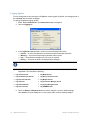
Certificate Management
By default, RingMaster does not accept self-signed certificates from MXs or from the monitoring
service. You can change this option in the Preferences dialog box. (For more information about
certificate handling, see Certificate Check.
To change certificate management options:
1. Select Tools > Certificates. The Certificate Management dialog box appears.
2. To automatically accept self-signed certificates, click to check the Always accept self-signed
certificates checkbox. To clear this option, clear Always accept self-signed certificates
checkbox. By default, this option is disabled. The RingMaster Client accepts a certificate only
if it is signed by a Certificate Authority (CA). You see a list of certificates in use and have
buttons to see Details and to Delete.
Click Close to close the Certificate Management dialog box, or click another tab to continue
making changes.
Copyright © 2011, Juniper Networks, Inc.
RingMaster Client Preferences
41
42
RingMaster Client Preferences
Copyright © 2011, Juniper Networks, Inc.
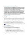
Managing with RingMaster
This chapter provides information on deploying services — enabling services for wireless clients on a
network. It also provides information about configuring MX management services and performing
administrative tasks. For detailed information on performing administrative tasks on an MX, refer to
“Configuring MX System Parameters” in the publication RingMaster Configuration Guide.
New Features in RingMaster
There are a number of new feature in RingMaster :
❑
Database improvements in RingMaster Software
With the release of RingMaster Version 7.4, a new relational database is supported that
allows you greater scalability with larger deployments of RingMaster. While this is
transparent to you when you install this version, you should be aware of the changes as
you upgrade your current version of RingMaster or perform a fresh installation of
RingMaster.
❑
Reporting Enhancements in RingMaster Software
You can now store reports on an FTP server in your network or store them locally.
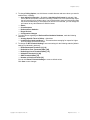
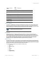
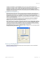
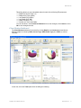
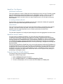
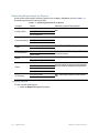
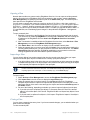
Audit Trail
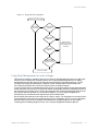
RingMaster Server software receives and stores audit records in an internal or external database.
If a client sends a specific audit record to the server, the server extends an audit record with other
information (session details, the system time, etc.) and stores the record in a database. Before storing
records, the server adapts audit records based on their database format. The server retrieves audit
entries from the database using a filter, then it sends these audit entries to a client to display them. A
simple diagram for this flow is shown below:
Add server-specific
record entries
Client
Send client audit
Server
Acct
Audit
Record
Store
Audit
Record
Retrieve
Filter
RADIUS
Local
Audit
Operations Tracked
Operations tracked in audit files include the following:
❑
Client actions that send a change set to the server
❑
Client actions that do not send a change to the server, and
❑
Server actions
Copyright © 2011, Juniper Networks, Inc.
Managing with RingMaster
43
Client Actions Sent to Server
Client actions that send a Change Set to the server include one or more of the following:
❑
Finishing a Wizard (in RF Planning, Policy, Configuration, Verification, or Alarm views)
❑
Finishing a Properties dialog
❑
Pressing the Save button in the main window
❑
Deleting an object using a wizard or by pressing the Delete button in a form
❑
Perform a Copy & Paste
❑
Uploading an MX / Creating an MX / Deleting an MX
❑
Creating/Modifying/Deleting a Policy
❑
Uploading or Creating an MX with an existing policy
Client Actions Not Sent to Server
Client actions that do not send a Change Set to the server include one or more of the following:
❑
Deploying
❑
Image Installation
❑
Accepting Network changes
❑
Undoing Local Changes
❑
Undoing Network Changes
❑
Applying a Policy
❑
Scheduling a Deploy
❑
Scheduling an Image Upgrade
❑
Managing / Unmanaging a device
Server Actions
Server actions that send a Change Set to the server include one or more of the following:
❑
Server Deployment
❑
Server Image Installation
❑
Merging object cache / Finishing a transaction
❑
Performing XML transactions (SET, DELETE, ACTION)
User Entries
The user audit entry stores information about user names and roles (e.g. administrator, monitor).
Time and Date Entries
Time and Date audit entries contain information about the time when an operation occurred. They
include the time zone by specifying an offset of minutes and hours.
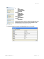
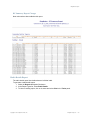
External Database
RingMaster stores audit records in an external RADIUS server as accounting information. Therefore,
RingMaster does not need to send accounting messages to a RADIUS server.
44
Radius Attribute
Name
RADI
US
Field Value
Value
Acct-Status-Type
40
Always set to STOP value
User-Name
1
The user name
Event-Timestamp
55
Timestamp of the event in UTC format
Calling-Station-Id
31
Ip address of the user
Managing with RingMaster
Copyright © 2011, Juniper Networks, Inc.
Managing with RingMaster
Radius Attribute
Name
RADI
US
Field Value
Value
Acct-Session-Id
44
Acct-Multi-Session-I 50
d
Unique accounting session id for each record
Unique value for a same user session
NAS-Port
5
TTY port or connection port used
NAS-Port-Type
61
Type of connection
NAS-IP-Address
4
MX Ip address
NAS-Identifier
32
Always set to "Trapeze"
Trapeze-Audit
13
A string VSA containing audit information
Access Control
In release 7.1, RingMaster’s access control capabilities are improved. This version provides a more
generic and flexible mechanism to allow you to set up access controls to meet specific operational
needs. This allows you to partition a network according to your specific requirements and define which
functions each type of user has authority to access in specific areas of a network.
Refer to the publication RingMaster Configuration Guide for details on
setting up Access Control for your network.
Data Model
Setting up access control begins by defining a User Group. You are no longer limited to three
pre-defined User types — administrator, provisioning user, and monitor user. After creating a user
group, privileges for that group can be associated with various sets of objects in a plan. For example,
you can assign configuration editing privileges for a specific MobilityDomain and its associated
member devices. After associating privileges for a set of objects to a user group, users can be
assigned to the group. Assigned users acquire the group’s privileges in the plan.
Object Group
An Object Group identifies a set of objects in a plan. Object Groups are defined as part of assigning
privileges to a user group. A separate object group is defined for each privilege type assigned to a user
group. An object group is bound to the user group for which it was originally created. The set of objects
an object group refers to can be referenced by other object groups.
The following types of objects may be added to an object group:
❑
Network Plan
❑
MX
❑
Mobility Domain
❑
Site
❑
Building
❑
Floor
❑
Location Group
❑
Equipment Group
Copyright © 2011, Juniper Networks, Inc.
Managing with RingMaster
45
Only two objects may be added to an object group. Furthermore, if two objects are choosen, each
must be of a different category as shown below (i.e. only one object per category).
❑
Location-related objects
❍ Location group
❍ Site
❍ Building
❍ Floor
❑
Equipment-related objects
❍ Equipment group
❍ Mobility Domain
❍ MX
Privileges
The following privileges may be assigned to a user group:
❑
Viewing of configuration data
❑
Editing of configuration data
❑
Viewing of monitoring data
❑
Server administration
User
Users are global entities shared across all plans. Their associations to user groups are maintained
across plans. A user can only be assigned to a single user group.
User Privileges
There are changes to user privileges for various views as detailed in the next paragraphs.
46
Managing with RingMaster
Copyright © 2011, Juniper Networks, Inc.
Managing with RingMaster
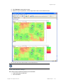
Configuration/RF Planning View
Privileges to view and edit configuration data are assigned to groups of objects in a plan. If a user
does not have viewing privileges for an object, that object will not appear in the organizer tree.
Configuration viewing privileges do not affect what is displayed in monitoring views. Monitoring is a
separate privilege. This allows an administrator to set up users whose primary role is for monitoring
only.
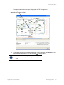
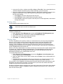
Organizer Tree
When a user switches to the configuration view, the root object in the organizer tree is the single object
(in the object group) associated with the configuration viewing privilege for that user’s assigned user
group (as shown in the example screen below).
Copyright © 2011, Juniper Networks, Inc.
Managing with RingMaster
47
Object Editing
If a user does not have editing privileges for an object, all tasks involving modifications to that object
are unavailable. All configuration data input fields for that object are disabled in the main details panel.
In some cases, a user may have editing privileges for an object, but a change causes a modification of
some other object that they are not privileged to edit. In this case, the change and all other side effect
changes involved in the transaction are rejected. An error message is dosplayed, informing the user of
an access control violation.
Configuration Tasks
Available configuration tasks include:
❑
NetworkPlan
❍ Create Mobility Domain
❍ Create Mobility Exchange
❍ Create Equipment Group
❍ Create Third Party AP
❍ Country Code
❍ Channel Set
❍ Disable Auto-Tune
❍ Authentication Mode
❍ AP Local Switching
❍ SmartPass Server
❍ Set Up AirDefense
❍ Launch AirDefense UI
❍ Create AirDefense Sensor
48
Managing with RingMaster
Copyright © 2011, Juniper Networks, Inc.
Managing with RingMaster
Upload MX
Convert Auto AP
❍ Remove Auto AP
❍ Network Domain
MobilityDomain
❍ Mobility Exchange
❍ Create Equipment Group
❍ Setup MX-MX Security
❍ AP Signature
❍ AP Redundancy
❍ Add Members to Cluster
❍ Remove Members from Cluster
❍ Remove Secondary Seed
❍ Delete cluster
❍ Upload MX
MX
❍ Review
❍ Deploy
❍ System Setup
❍ Software Version
❍ Model
❍ Authentication Mode
❍ Time
❍ System Information
❍ Add to Cluster
❍ Go to Monitor
❍ Go to Verification
❍ Go to Alarms
❍ Go to RF View
Third Party APs
❍ Create Third Party AP
❍ Create Ignore List Entry
❍
❍
❑
❑
❑
Copyright © 2011, Juniper Networks, Inc.
Managing with RingMaster
49
Verification View
The Verification view displays information on objects for which a user has configuration viewing
privileges. Summary counts displayed on the status line at the bottom of the main screen are based on
access control-filtered results. Resolutions are disabled if a user does not have editing privileges for an
associated object. Verification options setup requires server administration privileges.
Policy View
Access control for a policy object is derived based on the specific policy’s set of associated devices.
Users having viewing privileges for at least one of a policy’s associated devices will be allowed to view
the policy’s configuration data. To create, delete, or edit a policy, a user must have edit privileges for
the entire plan. This is required because, once a policy is created, it can result in automatic device
configuration changes. This can occur whenever a device is created or uploaded. As part of these
operations, the system searches for policies that match a device’s model and version. The base
configuration of these matching policy objects is automatically applied to the new device. To associate
a new device with a policy, a user edits the privileges for the device being associated. In order to apply
policy changes to member devices, a user must have edit privileges for all of the policy’s associated
devices. A user will only be allowed to review policy changes for the set of devices for which they have
configuration viewing privileges.
Devices View
The set of MXs displayed in a devices view is based on a user’s configuration viewing privileges. The
ability to invoke tasks for selected devices may require additional privileges. The table below lists
these requirements. The MX Credentials column is used to indicate that, in addition to RingMaster
privileges, the user must also provide a valid username/password for the target MX. By default, the
user’s RingMaster credentials are used.
50
Managing with RingMaster
Copyright © 2011, Juniper Networks, Inc.
Managing with RingMaster
Required Privilege for Device
Task
Config.
Editing
MX
Credentia
ls
Deploy
●
●
Undo Local Changes
●
Review Local Changes
Review Network Changes
Config.
Viewing
●
●
Accept Network Changes
●
Undo Network Changes
●
Go to Configuration
●
Go to Verification
●
Refresh
●
Upload MX
View Operations Log
●
Image Install
●
●
Reboot MX
Manage/Unmanage
●
●
Distribute Certificates
Image Repository
●
●
Reports View
Access to certain reports requires configuration data viewing privileges. When generating reports, a
user must select a scope. All scope types are available for selection, but object instances for each type
are limited to those for which the user has access. A user must have configuration viewing privileges
for an object as a whole in order for an object to appear in the selection list. In addition to report
generation, access control is enforced for the set of pre-existing reports available for viewing. For each
report stored on the server, information is maintained regarding the set of objects represented in the
report. If a user attempts to view a pre-existing report, a check is performed to ensure the user has
configuration viewing privileges for the complete set of referenced objects.
The reports shown below require configuration data viewing privileges. Access to other reports will be
based on monitoring privileges.
Report
Available Search Scopes
Inventory
NetworkPlan, MobilityDomain
Mobility Domain Configuration
MobilityDomain
Copyright © 2011, Juniper Networks, Inc.
Managing with RingMaster
51
Report
Available Search Scopes
MX Configuration
MX
Site Survey Order, Work Order
NetworkPlan, Site, OutdoorArea ,Building, Floor
Monitoring Privileges
The ability to view monitoring data for objects in a plan is a separate privilege that must be assigned to
a user group explicitly. The privilege to view configuration data does not imply monitoring access.
Likewise, monitoring access does not imply the ability to view configuration data.
Organizer Tree
When a user switches to the Monitoring view, the root object in the organizer tree is the single object
(in the object group) associated with the monitoring viewing privilege for that user’s assigned user
group. By setting the organizer root node this way, a user always has full monitoring privileges for
everything in the tree. This avoids the complexity of calculating access control-filtered monitoring
results for nodes in the tree for which the user has only partial access.
Find Clients
The Find Clients task is launchable from the client panel in the status summary tab as well as from
the Client Details monitor tab. When a task is invoked, a dialog appears with the current scope object
pre-selected as the initial search criteria. To enforce access control restrictions, the ability to change
this search scope to some other object in the plan is removed.
Find RFID Tag
The Find RFID Tag task is launchable from the Client Details monitor tab. This task is always
present, regardless of the organizer tree’s current scope selection. The dialog for this task contains
controls to search a specific MobilityDomain or a specific device. Similar to the Find Clients task, this
dialog allows you to change search criteria to an object different from the current tree selection. To
prevent users from invoking searches against devices for which they do not have monitoring
privileges, this task is only available in the context of a MobilityDomain or device tree selection. Users
are not be allowed to alter pre-selected scope values in the dialog.
Report Tasks
The Client, Traffic, and Radio Monitor tabs contain tasks that generate reports related to particular
areas of monitoring. When a task’s dialog is launched, the current tree object is pre-selected in the
search criteria fields. Users are allowed to change to some other object in the plan. These dialogs do
not allow pre-selected values to be altered.
Aalarms View
The Alarms view displays alarms for objects in a user’s allowed monitoring set. Alarm counts on the
summary line at the bottom of the frame reflect this. The alarm query function restricts the scopes by
which a user is allowed to search. In the dialog used to enter search criteria, the scope type field
contains possible values. Upon selection, however, the instance field only contains selections for
objects in a user’s allowed monitoring set.
Security View
The Security view previously provided a Network Plan-wide view of rogues and their associated
clients. This information is based on certain types of alarms raised against device objects. This view is
changed so it only displays information based on alarms raised against devices in a user’s allowed
monitoring set.
52
Managing with RingMaster
Copyright © 2011, Juniper Networks, Inc.
Managing with RingMaster
Reports View
Tasks available in Reports are based a user's privileges and limits the generation and viewing of
reports. The following reports are based on a user’s monitoring privileges:
Report
Available Search Scopes
Client Summary,
Client Errors
NetworkPlan, MobilityDomain, MX,
Site, OutdoorArea, Building, Floor,
CoverageArea
Dialog only prompts for username, IP
address, and client MAC as search criteria.
Report generation logic needs to filter the
results to only display the clients associated
with the set of devices per user has
privileges.
Client Details
Top APs
NetworkPlan, MobilityDomain, MX,
Site, OutdoorArea, Building, Floor
Network Usage
(Port Traffic)
NetworkPlan, MobilityDomain, MX
Network Usage
(Radio Traffic)
NetworkPlan, MobilityDomain, Site,
Building, Floor, AP, Radio
Dialog only prompts for MAC address.
Report generation logic should filter the
results to only display rogue information if it
was detected by a device in the user’s
allowed monitoring set.
Rogue Details
RF Summary
Notes
Site, OutdoorArea, Building, Floor,
AP, Radio
Dialog does not prompt for any search
criteria. Report generation logic should filter
the results to only display information related
to the devices in the user’s allowed
monitoring set.
Security
Radio Details
Radio
Rogue Summary,
Alarm Summary,
Alarm History
NetworkPlan, MobilityDomain, Site,
OutdoorArea, Building, Floor
Client OUI
Dialog does not prompt for any search
criteria. ISSUE: What type of filtering needs
to be done?
Web Pages
Access Control web pages support configuration for:
❑
User,
❑
User Group, and
❑
Radius Servers
Copyright © 2011, Juniper Networks, Inc.
Managing with RingMaster
53
On the Access Control Web page you can enable or disable Access Control functionality. You can
perform user operations on this page. On the RADIUS Servers page you can set up the parameters
for RADIUS Servers.
Grouping
As networks continue to scale, the need for a network partitioning feature grows. With larger
installations, responsibility for managing a network is distributed among individuals, where each one is
concerned only with a particular subset of the overall network. The way networks are partitioned is
dependent on the structure of the associated business. It may be physical location-oriented (e.g. a
group of Sites), or it may be more logical (e.g. department-oriented).
This feature provides a user flexibility to partition a network in a way that matches their organization
and their IT support group. The access control feature provides an ability for an administrator to assign
privileges to various entities throughout a network. Network partitioning provides a way of identifying
entities at a high level, rather than individually.
Refer to the publication RingMaster Configuration Guide for details on
setting up Groups for your network.
Object Groups
Two types of object grouping schemes are supported:
❑
Equipment groups, and
❑
Location groups.
There is no direct relation between these two and users may choose to use both, just one, or no
grouping scheme at all.
Equipment Group
An equipment group can contain the following types of objects:
❑
MobilityDomain – All member devices are implicitly included as equipment group members.
❑
Standalone MX – A device not associated with a MobilityDomain
❑
MobilityDomain member MX – A device associated with a MobilityDomain where the
MobilityDomain as a whole is not a member of the equipment group.
Equipment groups can be created under a top-level plan object, or under a MobilityDomain.
Organizer
The equipment organizer tree is enhanced to support the concept of equipment groups. Equipment
group nodes appear in the tree to contain associated device and/or MobilityDomain members. Device
nodes hang directly under an equipment group node, unless a device’s Mobility Domain is a member
of the group. Selecting a device node, reveals any MobilityDomain membership information in the
configuration view’s detail panel.
Cluster Configuration
Whenever a Mobility Domain is cluster-enabled, an associated Cluster node will appear in the
organizer. This node will contain the cluster’s seeds, members, and the DomainConfiguration node.
The following example illustrates a simple case involving no equipment groups. A MobilityDomain’s
cluster node may appear multiple times in the tree. There is no method for assigning a cluster as a
whole to an equipment group. Only devices and MobilityDomains can be assigned to a group. One
restriction is enforced regarding assignment of devices to equipment groups, which is that, if a device
is a cluster seed, the other cluster seed must also be assigned to the same equipment group. This is
required to ensure that a deploy target switchover will not to be rejected due to access control
restrictions.
Flat View
The organizer is enhanced to provide a context-sensitive “flatten” operation that can be invoked on
group nodes. This transforms a selected subtree into a flat list of immediate child nodes. Child node
54
Managing with RingMaster
Copyright © 2011, Juniper Networks, Inc.
Managing with RingMaster
labels include the labels of all collapsed parent nodes, separated by a “:” character. Only members of
the equipment group will be represented as child nodes.
Group Creation
Equipment groups are created in the configuration view by selecting a top-level plan object or a
MobilityDomain object and invoking a Create Group task. This opens a dialog where you assign a
name to the group and select objects to become members.
Location Group
A location group is used to group RF planning-related objects. A location group is limited to Site
containment. In future releases, this may be enhanced to allow individual buildings, floors, outdoor
areas, coverage areas, and placed AP to be added to a location group.
Group Usage
Monitoring View
Support for equipment groups and location groups has been added to the Monitoring view. Location
and equipment groups are represented in the monitoring view’s organizer. The tree nodes for these
objects provide a scope for displaying group-specific aggregated monitoring data. The monitoring view
organizer provides a way to inhibit the display of group objects in the tree. The organizer contains a
toggle button to control whether or not group nodes are displayed.
Client Monitor
The Client Summary view is enhanced to provide a Clients by Location Group option when a plan
object is the selected scope in the Sites organizer. If the organizer is in Equipment mode, a Clients
by Equipment Group option is provided when the plan object is the selected scope. The Find Clients
function is enhanced to provide searching by a location group or equipment group
Reporting
The scope selection feature in the reporting module supports the new location and equipment group
objects. The table below lists each type of report and the type of support that has been added.
New
Sup
Report Type
Report Type
Equipme
nt Group
Inventory
Network Plan, Mobility Domain
Y
Mobility Domain
Configuration
Mobility Domain
MX Configuration
Mobility Exchange
Client Summary
Network Plan, Mobility Domain, Mobility Exchange, Site,
Outdoor Area, Building, Floor, Coverage Area
Y
Client Errors
Network Plan, Mobility Domain, Mobility Exchange, Site,
Outdoor Area, Building, Floor, Coverage Area
Y
Top APs
Network Plan, Mobility Domain, Mobility Exchange, Site,
Outdoor Area, Building, Floor
Y
Network Plan, Mobility Domain, Mobility Exchange
Y
Client Details
Network Usage (Port
Traffic)
Copyright © 2011, Juniper Networks, Inc.
Managing with RingMaster
55
New
Sup
Report Type
Report Type
Equipme
nt Group
Network Usage (Radio
Traffic)
Network Plan, Mobility Domain, Site, Building, Floor, AP,
Radio
Y
RF Summary
Site, Outdoor Area, Building, Floor, AP, Radio
Radio Details
Radio
Rogue Summary
Network Plan, Mobility Domain, Site, Outdoor Area,
Building, Floor
Y
Alarm Summary
Network Plan, Mobility Domain, Site, Outdoor Area,
Building, Floor
Y
Alarm History
Network Plan, Mobility Domain, Site, Outdoor Area,
Building, Floor
Y
Rogue Details
Security
Client OUI
Site Survey Order
Network Plan, Site, Building, Floor, Outdoor Area
Work Order
Network Plan, Site, Building, Floor, Outdoor Area
Alarm Queries
The query feature in the Alarms view is enhanced to support filtering by instances of equipment group
or location group.
RADIUS Authentication
Currently, RingMaster uses basic authentication in which user names and passwords are stored in a
local data store. In addition, RADIUS-based authentication is supported by RingMaster.
A new option is available to enable RADIUS Authentication. If this option is enabled, a user must
provide the following RADIUS server information:
❑
IP Address
❑
Key
❑
Port (default 1812)
❑
Timeout (default 5 seconds)
❑
Retry Count (default 3 retries)
56
Managing with RingMaster
Copyright © 2011, Juniper Networks, Inc.
Managing with RingMaster
Users can configure one primary RADIUS server and one secondary RADIUS server globally, across
all network plans. If a user is successfully authenticated, the RADIUS server will send an Access
Accept response. This response will contain a custom VSA (Trpz-RM-User-Group) for the user group
to which the user belongs. RingMaster software restricts user access based on the user group
returned by the RADIUS Server. If RADIUS authentication is enabled, users must specify a default
user group. This user group is used if the RADIUS server does not return a VSA. If the RADIUS server
returns an invalid VSA, user access is rejected.
The administrator is able to configure local users. This is optional. Administrators can provision a user
and not have to wait until the user is added to a central RADIUS server. Any user trying to connect to
the RingMaster Server is first authenticated locally. If local authentication fails, the user is
authenticated using the configured RADIUS server. If access control is enabled, there should be at
least one user configured locally. This ensurse that a user can access RingMaster even if the RADIUS
server is unreachable.
RingMaster Server RM-200
The RM-200 platform provides a means of choosing between RADIUS-based authentication and its
current local authentication with regards to its Web and CLI platform management interfaces.
Managing the LA-200E
With the acquisition of Newbury Networks, the LA-200E is now a premier product for Trapeze Networks.
Integrating the LA-200E with RingMaster allows you to manage an LA-200E using network management software.
After adding the LA-200E to your network plan, you can manage, plan, and configure RFID listening APs from a
central server.
The integration of the LA-200E into RingMaster is supported by software version 6.4.1 or higher on the
LA-200E.
Adding a Managed LA-200E to RingMaster
To add an LA-200E to RingMaster, you must install an LA-200E in your wiring closet or have it located somewhere
in your network. After installation, you need the following information to add the LA-200E to RingMaster:
❑
IP Address
❑
User Name
❑
Password
Copyright © 2011, Juniper Networks, Inc.
Managing with RingMaster
57
You also need a Location Appliance license in order to activate the feature in RingMaster. After installing the
license, the Create Location Server task is available in the RingMaster interface.
Location Appliance License
RingMaster 7.4 with an activated Location Appliance license.
To add an LA-200E to RingMaster, follow these steps:
1. Open RingMaster and click Configuration from the menu bar.
2. From the Organizer panel, select Application Servers.
58
Managing with RingMaster
Copyright © 2011, Juniper Networks, Inc.
Managing with RingMaster
3. From the Task list, select Create Location Server and the associated wizard opens.
4. Select Managed to allow RingMaster to manage the location appliance.
5. In the Name field, enter the name of the LA-200E.
6. Enter the IP address.
7. Enter the User Name.
8. Enter the Password.
9. If there is a management password, enter the password in the Management Password field.
10. Click Next. RingMaster connects to the LA-200E and establishes a connection.
11. Click Finish to complete the configuration.
The LA-200E now appears in the Organizer panel under Application Servers.
To review LA-200E settings, highlight the Location Appliance in the list and click Properties. You can then change
any of the original settings for the server.
Available Tasks for All Managed LA-200E Location Appliances
There is a list of available tasks for all location appliances managed by RingMaster. You can select any of the
following tasks:
❑
Create Location Server
❑
Setup Synchronization Parameters
❑
Edit a Location Server
❑
Configure a Snoop Filter
❑
Configure SNMP Settings
From the Other List, you can select from the following tasks:
❑
Platform Management
❑
Appliance Logs
❑
Backup and Restore
❑
Configuration
❑
Factory Reset
❑
Schedule Reboot
❑
System Update
❑
User Management
Selecting any of the Other tasks opens the corresponding software feature on the location appliance. For more
information on using these features, refer to the Trapeze Networks LA-200E User's Guide.
Copyright © 2011, Juniper Networks, Inc.
Managing with RingMaster
59
Available Location Appliance Tasks
If the location appliance already has a configuration, the details are displayed when you select the LA-200E in the
Organizer panel.
After it is selected, the following information is displayed:
❑
Location Server
❑
Managed
❑
Name
❑
Port
❑
Version
❑
IP Address
❑
Locales
❑
Name
❑
Description
❑
Associated Fingerprints
❑
Associated Floor
❑
RF Fingerprints
❑
Name
❑
Description
❑
Associated Locale
In the Tasks panel, you can select from a list of available tasks. Under Create, you can select
❑
Create Locale
❑
Create RF Fingerprint
Under Setup, you can select
❑
Synchronize
❑
Edit Location Server
60
Managing with RingMaster
Copyright © 2011, Juniper Networks, Inc.
Managing with RingMaster
Snoop Filter
SNMP
Under Other, you can select
❑
Platform Management
❑
Appliance Logs
❑
Backup and Restore
❑
Configuration
❑
Factory Reset
❑
Schedule Reboot
❑
System Update
❑
User Management
Selecting any tasks under Other, opens the operating system of the location appliance and you can perform any
of these tasks directly on the location appliance.
❑
❑
Creating Locales Using RingMaster
Select an LA-200E from the Application Servers list in the Organizer panel. The Task list is now populated with
available tasks to perform on the location appliance. To create a locale, use the following steps:
1. Under Create, click Create Locale. The Create Locale Wizard is displayed.
2. Enter the name and description of the locale in the appropriate fields. Create RF Fingerprint
is selected by default. If you do not want to create an RF Fingerprint, clear the checkbox. If you
are also using Active Asset on the location appliance, you must follow a specific format for the
description. The format is Campus:Building:Floor. Click Next.
Copyright © 2011, Juniper Networks, Inc.
Managing with RingMaster
61
3. Enter the RF Fingerprint information including Name and Description. Click Next.
4. If there are other RF Fingerprints configured on the location appliance, they are displayed in
the Available RF Fingerprints list. You can select one and add it to the Current RF
Fingerprints list. You can also remove RF Fingerprints by selecting one from the Current RF
Fingerprints list and clicking Remove.
5. Click Finish to complete the configuration. The new locale and RF Fingerprints appear in the
Location Server and RF Fingerprints section. You can view the properties of a RF Fingerprints
by selecting it and then clicking Properties.
Added Locale
Added RF Fingerprint
62
Managing with RingMaster
Copyright © 2011, Juniper Networks, Inc.
Managing with RingMaster
Creating Locales Using RF Planning
You can also create Locales using the RF Planning feature of RingMaster. Click RF Planning and select a plan
from the Organizer. You can also import locales from CAD drawings.
Under Location Services, click Create Locale. The Create Locale wizard is displayed.
Copyright © 2011, Juniper Networks, Inc.
Managing with RingMaster
63
When you use the Drawing tools to draw the Locale, the Create a Locale wizard is displayed.
64
Managing with RingMaster
Copyright © 2011, Juniper Networks, Inc.
Managing with RingMaster
1. Select a Location Server from the list and click Next.
2. You can now select an existing locale or create a new locale. If you select an existing locale,
click Finish to complete the configuration. If you select Create a Locale, click Next.
3. Type a name and description of the Locale in the Name and Description fields. Click Finish to
complete the configuration.
Copyright © 2011, Juniper Networks, Inc.
Managing with RingMaster
65
Adding RF Fingerprints Using RF Planning
You can add RF Fingerprints to the Locale you just created by clicking RF Fingerprint in the Task list. When you
move your cursor over the locale, it changes to a crosshair. Click and drag to display the RF Fingerprint wizard.
Enter a name and description for the RF Fingerprint and click OK. The RF Fingerprint now appears on the Locale.
Calibrating RF Fingerprints Using RF Planning
To calibrate an RF Fingerprint, click on the fingerprint icon in the locale to select it. Then click Calibrate RF
Fingerprint.
Enter the MAC address of the device and click Start. You can see the status in the Progress bar. Once the
process is complete, you can click Next to add it to the locale.
Creating RF Fingerprints
Select an LA-200E from the Application Servers list in the Organizer panel. The Task list is now populated with
available tasks to perform on the location appliance. To create a RF Fingerprint, use the following steps:
66
Managing with RingMaster
Copyright © 2011, Juniper Networks, Inc.
Managing with RingMaster
1. Under Create, click Create RF Fingerprint. The wizard is displayed.
2. Enter a name and description for the RF Fingerprint.
3. Click Next.
4. Select a locale from the Associated Locale list to associate with the RF Fingerprint.
5. Click Finish to complete the configuration.
The RF Fingerprint now appears in the Locales list and the RF Fingerprints list.
Copyright © 2011, Juniper Networks, Inc.
Managing with RingMaster
67
Setting Up a Location Appliance Using RingMaster
Select an LA-200E from the Application Servers list in the Organizer panel. The Task list is now populated with
available tasks to perform on the location appliance.
Synchronizing Changes on a Location Appliance using RingMaster
To synchronize configurations on a location appliance, use the following steps:
1. In the Task list, click Synchronize.
2. The Review Changes panel is displayed.
3. You can select from two types of action:
❍ Deploy Changes to the location appliance - changes made using RingMaster are
applied to the location appliance.
❍ Accept Changes from the location appliance - changes made on the location appliance are uploaded to RingMaster.
You cannot undo this operation. Once you click Next, the changes are synchronized between
RingMaster and the LA-200.
4. Click Next. The changes are synchronized between RingMaster and the location appliance.
5. Click Finish to complete the operation.
The LA-200 image created using RingMaster is transferred to the LA-200 where it is used by other
applications such as Active Asset. It is recommended that you create a backup of your current image
before transferring the new on to the LA-200.
Editing Location Appliance Attributes Using RingMaster
To edit a location appliance, select it from the list of Application Servers. Then follow these steps:
68
Managing with RingMaster
Copyright © 2011, Juniper Networks, Inc.
Managing with RingMaster
1. Click Edit Location Server to display the attributes for the server.
2. You can modify any of the listed attributes, and click Next.
3. RingMaster establishes a connection with the location appliance.
4. Click Finish to send the changes to the location appliance.
Configuring a Snoop Filter for a Location Appliance
You can configure a snoop filter on an MX using RingMaster and apply it to a location appliance. To configure a
snoop filter, follow these steps:
1. In the Task list, under Setup, click Snoop Filter.
2. Select an MX to target from the Select a MX list.
3. Click Next.
Copyright © 2011, Juniper Networks, Inc.
Managing with RingMaster
69
4. If there is an existing Snoop Filter on the MX, you can select it from the Filters list. If a Snoop
Filter is not configured, you can select Create a Filter. Click Next.
5. In the Snoop Filter Name field, enter a name for the filter. Select Enabled to begin using the
filter. Click Next.
6. Configure the Snoop Filter Observer. You must specify the following information:
❍ Target IP Address
❍ Snap Length Limit (optional)
❍ Frame Gap Limit (optional)
70
Managing with RingMaster
Copyright © 2011, Juniper Networks, Inc.
Managing with RingMaster
7. Click Next.
8. Optionally, you can create Snoop Filter Conditions by specifying a list of conditions that
match the criteria for packets. The following conditions can be added to the Snoop Filter:
❍ Direction
❍ Frame Type
❍ Channel
❍ BSSID
❍ Source MAC
❍ Destination MAC
❍ Host MAC
❍ MAC Pair
When you select a condition, a list of attributes is displayed that can be applied to it. Click Next
.
9. You can also configure optional Snoop Mapping by selecting radios on an MP to map the
Snoop Filter. Click Next.
10. Additionally, you can map a Snoop Filter to a specific radio profile. Select one from the
Available Radio Profiles list and click Add to move it into the Current Radio Profiles list.
11. Click Finish to complete the Snoop Filter configuration.
Copyright © 2011, Juniper Networks, Inc.
Managing with RingMaster
71
Configuring SNMP for a Location Appliance
You can configure SNMP settings for the Location Appliance using the RingMaster interface. Select a Location
Appliance from the list in the Organizer panel and then click SNMP.
You need the following information to configure SNMP targets on the Location Appliance:
❑
Destination Host
❑
Destination Port
❑
SNMP Version
72
Managing with RingMaster
Copyright © 2011, Juniper Networks, Inc.
Managing with RingMaster
If you select SNMP Version v2c, then you configure the SNMPv2c Settings. If you select SNMPv3, then you
configure the SNMPV3 settings. Click Next to continue with the configuration.
If you a secondary SNMP target, you can configure it by entering the appropriate information. Click Finish to
complete the configuration.
All tasks listed under Other are performed on the LA-200E using the LA-200E user interface. Consult the Trapeze
LA-200 User’s Guide to perform any of these tasks.
Copyright © 2011, Juniper Networks, Inc.
Managing with RingMaster
73
Monitoring the LA-200E
You can see the following status information on the LA-200E when you click Monitoring and then select the
LA-200E from the Organizer panel.
The Monitor feature displays the following information:
❑
Status Summary — click Details for more information.
❍ Appliance Name
❍ Status
❍ Admin Status
❍ IP Address
❍ Server Type
❍ Management Port
❍ Version
❍ Up Time
❑
Alarm Summary — click Details for more information.
74
Managing with RingMaster
Copyright © 2011, Juniper Networks, Inc.
Managing with RingMaster
❑
Clients by Locale — you can also click Find Clients to search for clients on the network.
❑
Tracked Devices by Type
Additional LA-200E Areas Monitored by RingMaster
There are additional features on the LA-200E that can be monitored by RingMaster. When you select a floor with
a LA-200E, a new Show Devices task is available. This task displays all the devices tracked by the LA-200E
including:
❑
Clients
❑
Tags
❑
APs
❑
Rogue APs
You can filter the devices displayed using the following strings:
❑
SSID
❑
User Name
❑
MAC Address
❑
IP Address
❑
End Address for SIP
❑
Radio Technology
When you use the filtering capabilities, only the devices matching the filter are displayed. Once you clear the
criteria, all devices are displayed again.
You can also hide or display the following items on the Monitoring interface:
❑
Locales
❑
Fingerprints
❑
APs
❑
Clients (Voice and Data)
❑
Tags
❑
Rogue APs
❑
Client and AP Connections
When you select Show Devices and then select an asset tag, you can see the temperature of the tag as well as
the battery life for the tag.
Copyright © 2011, Juniper Networks, Inc.
Managing with RingMaster
75
Managing Devices
Clicking on the Devices button on the Navigation Bar brings up the following window containing the
Devices Dashboard:
The Tasks panel contents change depending on whether the Change Management or the
Device Operations tab near its bottom are selected. The next paragraphs describe the items shown
in the Tasks panel for each.
Change Management Tab Items
This dashboard provides information on MXs in a network, and provides access to the following
functions and or tasks:
❍Local
Changes
◆Review
◆Deploy
◆Schedule
Deploy
◆Undo
❍Network
Changes
◆Review
◆Accept
◆Undo
❍Go
To
to Configuration
◆Go to Verification
◆Go
❍Other
◆Refresh
◆Upload
MX
Operations Log
◆Cancel Operation
◆View
Local Changes
Undo deletes all local changes from RingMaster. Deleted
changes will not be deployed to an MX.
76
Managing with RingMaster
Copyright © 2011, Juniper Networks, Inc.
Managing with RingMaster
Network Changes
Network changes can be reviewed in the same manner as local changes. Click Review to
examine items created, deleted, or modified on an MX via CLI, Webview or another instance of
RingMaster appliance. Click Accept to store network changes in RingMaster and allow them to be
managed. To cancel or undo network changes and revert an MX configuration to the stored
RingMaster configuration, do this:
1. Click Undo network changes.
2. Click Deploy local changes.
All local changes made before clicking “Undo network changes” will be
deployed at step 2.
Device Operations Tab Items
❍
❍Images
◆Image
Install
Install
◆Image Repository
◆Schedule
❍Actions
◆Reboot
MXs
Device
◆Unmanage Device
◆Distribute Certificates
◆Manage
❍Go
To
to Configuration
◆Go to Verification
◆Go
❍Other
◆Refresh
◆Upload
MX
Operations Log
◆Cancel Operation
◆View
Copyright © 2011, Juniper Networks, Inc.
Managing with RingMaster
77
Managing Policies
Selecting the Polcies button on the Navigation Bar shows policies related to a selected item in the
Organizer panel. The example below is for the policy pol_alphanet:
Policy Tab Items
❍
❍Policy
Changes
◆View
◆Apply
❍Setup
◆Areas
78
Managing with RingMaster
Copyright © 2011, Juniper Networks, Inc.
Managing with RingMaster
Viewing Policy Changes
After selecting the Policies tab, selecting View in the Tasks panel allows you to view policy changes.
Selecting an item in the Changed List of the dialog that appears shows policy changes related to that
item.
Click Print for a copy and Close when done.
Applying Policy Changes
After selecting the Policies tab, selecting Apply in the Tasks panel allows you to apply policy
changes. Selecting an item in the Changed List of the dialog that appears shows policy changes
related to that item. You see a dialog like that below:
Click Apply to apply changes and Close when done.
Copyright © 2011, Juniper Networks, Inc.
Managing with RingMaster
79
Selecting Policy Areas
After selecting the Policies tab, selecting Areas in the Tasks panel allows you to select policy areas.
You see a dialog like that below:
Click OK after making selections or Cancel when done.
Configuration Management
Any changes you make to a network in RingMaster are saved in a network plan on the server, but
changes are not applied to the network until they are deployed. You see changes in RingMaster, but
these changes are only present in a network plan until you deploy them to the MXs in a network. You
can apply a configuration to multiple MXs, or deploy changes to a single MX. RingMaster allows you
to deploy changes immediately, or to schedule deployment.
Reviewing Local Changes
Select device(s) with local changes and click Review. You see a dialog like that below:
Examine changes that will be made to an MX. The Review window is a table with expandable rows to
drill down to individual attributes. Created items are green, deleted items are orange, and modified
items are black. Click Print for a copy and Close when done.
Local changes cannot be deployed when network changes are detected. You
must first accept or undo network changes.
80
Managing with RingMaster
Copyright © 2011, Juniper Networks, Inc.
Managing with RingMaster
Deploying Local Changes
To deploy local changes immediately:
1. Select the Devices Navigation Bar button.
2. At the bottom of the Tasks panel, select Change Management.
3. Select one or more managed MXs. To select multiple MXs, press Shift (for contiguous MXs) or
Control (for non-contiguous MXs) while clicking. Multiple selection enables tasks applicable to
all selected devices, including reviewing local changes.
4. In the Local Changes group in the Tasks panel, click Deploy. The Deploy Configurations
dialog box appears. This dialog lists MX Mobility Domain, Version, Status, History and
Selected Errors.
Click Close.
This dialog may show verification errors. Resolve these using the Verification button on the Navigation
Bar. You can click Close at any time after clicking Deploy. The operation continues in the background.
To review the status of the operation, use the operation log. (Select View Operation Log in the Tasks
panel.)
Scheduling Deployment
To schedule local change deployment:
1. Select the Devices Navigation Bar button.
2. At the bottom of the Tasks panel Local changes group, select Schedule Deploy.
3. Select one or more MXs. To select multiple MXs, press Shift (for contiguous MXs) or Control
(for non-contiguous MXs) while clicking.
4. In the Tasks panel in the Local Changes group, click Schedule Deploy.
If there are errors preventing deployment, you see the following dialog:
When errors are cleared, this deployment must be repeated.
Copyright © 2011, Juniper Networks, Inc.
Managing with RingMaster
81
5. The Schedule Deploy dialog box appears.
6. Edit the Start date and Start time. (Date and time are based on the date and time on the
machine where RingMaster Services are installed.)
Click OK.
Verifying Deployment
1. Leave the Devices Navigation Bar button selected.
2. Look in the Deploy Status column for the switch(es) to which you deployed configuration
information. Their status should be Completed (Date). You also can verify successful
deployment by checking the operation log.
Tip
When a local change or image deploy hangs and is incomplete, an MX is locked by RingMaster and
cannot be modified. This is a special server-side lock that cannot be removed via the Lock Management
RingMaster server Web page. You must remove this lock by selecting an MX row and clicking Cancel
operation.
Accessing the Log
1. Select the Devices Navigation Bar button.
2. At the bottom of the Tasks panel, select Device Operations.
82
Managing with RingMaster
Copyright © 2011, Juniper Networks, Inc.
Managing with RingMaster
3. In the Tasks panel, select View Operations Log.
Performing Basic Administrative Tasks
This section contains information about basic administrative tasks you perform in RingMaster. For
detailed information about administrative tasks, such as configuring MX management services, refer to
the “Configuring MX System Parameters” chapter in the publication RingMaster 7.0 Configuration
Guide. For more information about image and file management, see the chapter “Managing MX
System Images and Configurations” in the Trapeze Mobility System Software Command Reference.
Configuring MX Management Services
You configure the following information and management services for an MX:
❑
System information — You can specify system contact information, as well as CLI prompt and
the banner message that appears in each session.
❑
HTTPS — By default, HTTPS is enabled. TCP port 443 is used for secure access by Web View,
the Trapeze Web-based application for managing an MX.
RingMaster communications also use HTTPS, but RingMaster is not affected by the
HTTPS configuration on an MX. For RingMaster, HTTPS is always enabled and
listens to port 8889.
Telnet — By default, Telnet is disabled. You can enable Telnet for unencrypted access to the
CLI.
❑
SSH — By default, SSH is enabled. You can use SSH for encrypted access to the CLI.
❑
SNMP — By default, SNMP is disabled. You can configure SNMP community strings and User
Security Model (USM) users, notification profiles, and notification targets.
❑
Logging — The system log provides event information for monitoring and troubleshooting. You
can send the log information to a local data buffer on an MX, to the console, to a Telnet session,
and to a configured set of syslog servers.
❑
Tracing — Tracing allows you to review diagnostic information for debugging MSS. Tracing
allows you to review messages about the status of a specific area of MSS.
❑
Time zone and summertime settings — You can statically configure system time and date. You
can configure MSS to offset the time by an additional hour for daylight savings time or similar
summertime period.
To manage services on an MX:
1. Select the Configuration Navigation Bar button.
2. In the Organizer panel, click the plus sign next to the MX.
❑
Copyright © 2011, Juniper Networks, Inc.
Managing with RingMaster
83
3. Click the plus sign next to System.
4. Select Management Services. Management services/settings appear in the Content panel.
5. Use the Content panel and Tasks options to modify settings. (For information about
management options, refer to the “Configuring MX System Parameters” chapter in the
publication RingMaster 7.0 Configuration Guide.)
Distributing System Images
You can use RingMaster to upgrade or downgrade a system image (MSS software) on MXs. System
images include switch software and AP software.
Using the Image Repository
Use the image repository to add or delete MX system images. An image file is checked
and its version verified when it is added to the image repository. Images are stored in the
RingMaster_installation_directory\images\dp directory.
To add a system image:
1. Select the Devices Navigation Bar button.
2. At the bottom of the Tasks panel, select Device Operations.
84
Managing with RingMaster
Copyright © 2011, Juniper Networks, Inc.
Managing with RingMaster
3. From the Tasks, select Image Repository.
4.
5.
6.
7.
Click Add Image. The Add to Repository dialog box appears.
Navigate to the directory containing the system image.
Select the system image.
Click Add to Repository. The image is added to the image repository and appears in the
Image List.
8. To close the Image Repository dialog box, click Close.
To delete a System Image:
1. In the Image Repository dialog box, select an image to delete.
2. Click Remove Image. A prompt appears.
3. Click Yes to delete the system image.
4. To close the Image Repository dialog box, click Close.
You can distribute a system image to one or more MXs in a network plan. To use a new system image,
you must reboot an MX.
Trapeze Networks recommends that you use the Verification button to resolve any
configuration errors or warnings before you distribute system images. See “Verifying
Configuration Changes” in the publication RingMaster Configuration Guide.
Before you can distribute an image, you must add it to the image repository. (See Using the
Image Repository.)
To immediately install an image on MXs:
1. Select Devices.
2. From the Tasks, select Device Operations.
3. From the Managed Devices list, select MXs to install the image. To select more than one MX,
click Shift while clicking to select contiguous items, or click Ctrl (Macintosh: Command) while
clicking to select noncontiguous items.
Copyright © 2011, Juniper Networks, Inc.
Managing with RingMaster
85
4. In the Tasks panel, select Image Install.
5. Click Select an Image to display the list of images in the repository.
6. Select the image and click Install.
To schedule installation of an image on MXs:
1. Select the Devices Navigation Bar button.
2. At the bottom of the Tasks panel, select Device Operations.
3. In the Managed Devices list, select the MXs to install an image. To select more than
one MX, click Shift while clicking to select contiguous items, or click Ctrl (Macintosh:
Command) while clicking to select noncontiguous items.
4. In the Tasks panel, select Schedule Install.
5. Click Select an Image to display the list of images in a repository. Click Next.
6. Edit the start date and time. (The date and time are based on the date and time on the
computer with the RingMaster Services installation.) Click Finish.
Saving Versions of Network Plans
You can save multiple versions of a network plan in RingMaster. After deploying a network plan to an
MX, you can save a snapshot of the plan as a version. You should create versions of a network plan
on a regular basis, and at major baseline events, for network configurations. This stores snapshots of
network configurations in case you need to revert to one of them. If you need to roll back configuration
changes, you use a saved version to roll back the software image and configuration files to a known
state. Before you save a version of a network plan, you must deploy and save the network plan.
Versions of network plans are saved in the db/xml/versions directory in the RingMaster installation
directory. After saving a version of a network plan, a version appears in the list of available network
plans. If you open a version of a network plan, you can deploy it or open it. When a version is open, its
version name is displayed in the title bar of the RingMaster window.
To save a version of a network plan:
1. Select Services > Plan Management. The Plan Management page is displayed in your
default browser.
86
Managing with RingMaster
Copyright © 2011, Juniper Networks, Inc.
Managing with RingMaster
2. In the left-hand column of the page, click Save As. The Save As Network Plan window is
displayed.
3. In the Network Plan Name field, type a name for the plan.
4. Click Save.
Saving Network Plans Automatically
By default, RingMaster uses the autosave feature to automatically save changes to a network plan at
regular intervals. To view or modify backup settings, select Services > Backup & Restore to display
Backup & Restore in a browser window.
Copyright © 2011, Juniper Networks, Inc.
Managing with RingMaster
87
RingMaster SNMP Agent
SNMP
Traps
AirDefense
Server
XML-based
APIs
Alarms/
Monitoring
Configuration
RingMaster Services
LA-200
RingMaster Client
Managed MXs
The RingMaster SNMP Agent provides access to allow upstream application programs to perform
WLAN management tasks without GUI interaction. An upstream application can retrieve the
configuration of MPs in a RingMaster managed network domain. This software can, for example, get
information on a set of MPs by serial number or MP type. After an upstream application binds to utilize
the RingMaster SNMP Agent, that application can initiate transactions using this interface.
The capabilities enabled by RingMaster SNMP Agent include:
❑
Client/session information
❑
Alarms
❑
Monitoring
❑
Security (rogues, neighbor lists, etc.)
❑
Policies
❑
Reports
❑
RF Planning
❑
Software Generics Management
Transactions enacted between upstream application(s) and the RingMaster SNMP Agent are often
scoped with regards to applicable managed entities. This limits the amount of time an upstream
application needs to process resulting information flows. RingMaster SNMP Agent’s interface meets
recommendations of standards authorities such as the World Wide Web Consortium (W3C). See the
figure above for a high-level view of interfaces. The RingMaster SNMP Agent software’s goal is to
provide programmable access to upstream applications so they can accomplish required WLAN
management tasks without GUI interaction. There are two interfaces that will be available as described
in the next paragraphs.
This interface allows use of an XML API to query configuration and monitoring data. It uses REST
based web services for easy integration. It uses standard Internet protocols including XML over
HTTPS,
Web Services API
The Web Services API is used to set up the SNMP interface and provide other alarm / inventory
details using polling rather than using a trap mechanism.
❑
The Agent version is the REST interface version which is not the same as the RingMaster
software version. This is defined for upgrades and future use.
❑
The Web API provides an alarm summary from the RingMaster alarm module (each alarm
type, criticality and their counts). The alarm summary can be filtered based on query criteria
using the Web API. (For example, client failure alarms with a certain SSID).
88
Managing with RingMaster
Copyright © 2011, Juniper Networks, Inc.
Managing with RingMaster
The Web API provides inventory information, such as a list of devices (MXs and APs) and their
information in RingMaster (name, model, serial number, build number, system IP, location,
contact info, admin state, and operational status).
For configuration of this API, refer to the publication RingMaster Web Services API.
❑
SNMP Traps
SNMP traps provide a standards-based mechanism for encoding and delivery of RingMaster alarms
and retrieval of status and configuration information.
The RingMaster Agent supports new components including the RM-200 Appliance.
The SNMP Trap interface is designed to provide an asynchronous mechanism for encoding and
delivering RingMaster alarms and monitoring information.
Areas of integration are:
❑
Fault Management — Monitors of enterprise network infrastructure, such as HP OpenView
❑
Security — WLAN intrusion detection and prevention systems (IDS/IPS), example, Enterasys
Dragon.
Network alarm notifications are made by:
❑
Correlation of SNMP Traps across MXs
❑
Correlation of AirDefense Traps across MXs
❑
Periodic audts by RingMaster
Configurable notification filters can be set using the SNMP Manager to filter alarms by:
❑
Alarm Category
❑
Alarm Severity
Alarm Notifications Via SNMP Traps
The SNMP interface deals primarily with alarm notification.
❑
The RingMaster Agent generates SNMP v1 and v2c traps.
❑
The SNMP interface forwards alarms as SNMP traps, including alarms created and correlated
from MX traps, alarms generated from RingMaster itself, and alarms collected from other
sources, such as AirDefense traps.
❑
The RingMaster agent sends an SNMP trap when an alarm’s state changes, such as when an
alarm is cleared or acknowledged, or when it is updated.
❑
To deal with a burst of cleared or new alarms, the RingMaster Agent buffers traps at a
configurable interval sends them during a specified interval. This update interval can be
configured via The RingMaster’s Web interface.
RingMaster Agent License
RingMaster Agent will be a licensed feature. The license SKU is RMTS-AGENT and it works just like
the RMTS-PLAN license. It needs a base RMTS license installed first.
Product
Code
SKU
Description
02
RMTS
Base license enabling support for up to 5 APs and one switch.
07
RMTS-AGENT
Enables RingMaster Agent feature
WebAPI Interface
The Web Services API provides a management interface. It allows third party applications to build
interfaces or applications to access or manage devices and alarms. For example, an upstream
application can retrieve the configuration of MPs in a RingMaster managed network domain. This can
be more than a basic query with respect to information requested — for example, a set of MPs
corresponding to certain serial numbers or MP type may be requested.
Copyright © 2011, Juniper Networks, Inc.
Managing with RingMaster
89
Automatic Image Update
This feature allows users with a SafetyNet login to automatically download MSS software images from
the Trapeze Networks support portal. In the past, customers had to connect to the Trapeze Networks
support portal to download new software images for MXs. The auto update feature allows users to
update software automatically on a scheduled or on-demand basis. Users will be notified when new
MSS software is available or downloaded.
This feature performs the following:
❑
Checks and downloads any new, compatible MSS software images
❑
Provides the ability to set up automatic updates
❑
Allows you to specify the frequency and time for automatic updates
❑
Provides notification options for automatic updates:
❍ Notifies when updates are available
❍ Notifies when updates are downloaded
❑
Allows you to perform manual updates
❑
Provides progress information for manual updates
❑
Checks the current version of MSS software on MXs currently in a plan and displays/downloads
only relevant software
Auto Update Wizard
The update panel will help you schedule auto updates or perform a manual update.
1. Select the Upgrade menu item on the Tools menu to bring up the following dialog:
You will be asked for a login User Name and Password. You can click a button to verify
username and password and to Update Now.
90
Managing with RingMaster
Copyright © 2011, Juniper Networks, Inc.
Managing with RingMaster
This button will check your SafetyNet Login User name and Password and confirm whether it
is valid or not and if so you see the window below. This dialog will list and allow you to
download updates when available. Click Close on this dialog.
When you select a manual update, you see:
❑
A list of compatible new versions of software, if available, displayed in a table. You can
select which software to download and click the Download button. If you select software,
corresponding files are downloaded
The system will display the status of the download.
2. If you clicked the Enable Auto Updates check box on the previous dialog and clicked Next
you see the following:
You have the option of scheduling an auto update or performing a manual update.
You can enable auto update, choose an update frequency at which to check the support portal:
❑
Daily
Copyright © 2011, Juniper Networks, Inc.
Managing with RingMaster
91
Monthly
Weekly
If you select daily, you then select a time If you select weekly, you then select a day of the week and
time. If you select monthly, you then select a date and time.
You are able to select one of the following actions:
❑
Notify when the updates are available
❑
Notify after the updates have been downloaded
❑
❑
92
Managing with RingMaster
Copyright © 2011, Juniper Networks, Inc.
Monitor Function
This chapter highlights the Monitor function, which displays information retrieved by RingMaster.
Monitor views show correlated data and let you navigate to details.
Monitoring Dashboards
Information is presented in a four-segment “dashboard” in the Content panel when you select the
Monitor Navigation Bar button:
❑
Status Summary — Shows high-level status for Trapeze equipment. This view changes based
on the selections in the Organizer panel — Domain, MX, AP or Radio can be selected.
❑
Client Summary — Shows activity, errors, and session information for network clients.
❑
Alarm Summary — Shows faults (alarms) for MXs.
❑
Traffic/Radio Summary — Shows Traffic Summary or Radio Summary depending on the
object selected in the tree. If an MX is selected, this segment shows a Traffic Summary, but if
an AP is selected the segment shows an RF Summary.
Each view provides answers to specific questions, such as the number of clients connected over the
last hour, and which MX has the most traffic load. The Status Summary, Alarms Summary, Clients,
Copyright © 2011, Juniper Networks, Inc.
Monitor Function
93
and Radio sections provide buttons so you can switch between graphical and tabular views in any
area. These buttons allow you to see the data behind graphs. RingMaster provides many monitoring
options. This section describes how to use these monitoring tools to determine problems that are
reported.
Clicking the Details button in any subview (area) provides more information about data in that view.
This chapter provides three monitoring examples to use as a guide to troubleshooting user
connectivity issues in a network. For example, clicking on Details in the Status Summary area brings
up a window like that shown below:
Requirements for Monitoring
To enable RingMaster Services to monitor network data, you must specify the MXs to monitor.
RingMaster Services software collects data from these MXs and updates it in views under the
Monitor Navigation Bar button for RingMaster clients. To specify the MXs to monitor, upload
configurations into RingMaster or add them to a network plan. In addition, enable SNMP traps on the
MXs. By default, the RingMaster Services supplies data to all views under the Monitor Navigation Bar
button. This data is refreshed at regular intervals, according to the polling interval configured for
RingMaster Services. The default polling interval is 15 minutes. You can optionally disable
RingMaster Services from supplying data to specified views. To configure RingMaster Services for
monitoring, see “Selecting Monitoring Settings” in the publication RingMaster Planning Guide. To
enable SNMP traps on MXs, see “Configuring SNMP” in the publication RingMaster Configuration
Guide
Network Types
Networks have varying requirements and expectations for network monitoring, depending on the type
of network being monitored. The two most common network types are corporate or campus networks,
and distributed networks with remote sites.
Corporate or Campus Networks
Corporate or campus networks have two to thirty two high-capacity MXs, such as MX-2800s. These
networks can include a high number of APs and clients in a wide variety of location types, including
94
Monitor Function
Copyright © 2011, Juniper Networks, Inc.
Monitor Function
multiple sites managed by a single RingMaster server. One or more mobility domains can be
configured for this type of network. RingMaster has sufficient bandwidth to periodically collect detailed
information from all MXs in such a network. With SNMP traps and all trending options enabled,
RingMaster collects data and provides network-wide reports on demand. RingMaster provides an
administrator with status and fault information, and the administrator can retrieve data at any time from
a single MX or an entire network.
Distributed Networks with Remote Sites
Distributed networks with remote sites have a large number of smaller MXs, such as MX-R-2s or
MX-8s, spread over a many sites — for example, branch offices or a chain of stores. Each site has few
APs and clients. Domains may not be configured for mobility because sites are geographically
distributed and each may have only a single MX. You can configure a network domain for this type of
network. For distributed networks, RingMaster communicates with MXs over a WAN. You can turn off
data collection and SNMP traps.
You can retrieve fault and status information, but cannot control what is collected or RingMaster
polling intervals. With RingMaster, the administrator of a distributed network can monitor and
diagnose a single site or MX by collecting data as needed.
While RingMaster collects graphical or tabular data, it might take longer to display data in one area
than it does in another. Consequently, RingMaster displays the message Loading data, please wait
in the chart or table area. However, RingMaster allows you to view data from another view while it
collects data from the previously selected view. In other words, RingMaster will load selected data in
the background so that you can view corresponding data in another section.
. In addition, you can print displayed tables
Refresh RingMaster data by clicking the Refresh icon
and graphs by clicking the Print icon
.
Monitoring With RingMaster
Monitoring capabilities decribed below depend upon restrictions placed on users as described in
Restricted User Monitor View.
Copyright © 2011, Juniper Networks, Inc.
Monitor Function
95
Restricted User Monitor View
Restricted users see a limited view after configuration, as shown in the example below:
This view shows only Monitor and Alarms buttons on the Navigation Bar.
❑
It does not show configuration error/warning counts, local/network change counts on the
Status Bar.
❑
Alarm counts on the Status Bar are filtered based on view restrictions selected.
96
Monitor Function
Copyright © 2011, Juniper Networks, Inc.
Monitor Function
Cluster Status Monitoring
In the Domain Status panel, you can click on Cluster Status to see the following:
MX Status Monitoring
In the MX Status panel, RingMaster shows the status of MX Status, including Fans,
Power Supplies, Licenses and a table of information about its Ports.
Copyright © 2011, Juniper Networks, Inc.
Monitor Function
97
AP Status Monitoring
In the AP Status panel, RingMaster shows a new AP Ports table that lists Port, Speed, Duplex, and
PoE for both ports.
In the AP Status table, there is a new column for PoE.
98
Monitor Function
Copyright © 2011, Juniper Networks, Inc.
Monitor Function
This table indicates both the Primary MX andd Backup MX that manage each AP. This provides an
indication of MX failover fro Primary to Backup, and failback when a Primary “returns”.
Radio Status Monitoring
RingMaster displays a Radio Status monitoring panel. The channel column shows both primary and
secondary channels (MP-432s only) in a format of (44, 48). For a radio that is using single channel, the
display format is just 44, as before.
Mesh Links Monitoring
Mesh Links monitoring view shows the Mesh Portal/Mesh AP, Mesh AP and SSID of each mesh link.
You can select a mesh link and click on Tasks panel items to view Link Properties, perform a Link
Test, or view Link Statistics.
Copyright © 2011, Juniper Networks, Inc.
Monitor Function
99
RF Neighborhood Monitoring
RF Neighborhood monitoring view shows the Mesh Portal/Mesh AP, Mesh AP and SSID of each
mesh link.
You can select radio buttons to Show RF Neighbors by:
❑
Transmitters (heard by this Radio)
❑
Listeners (who heard this Radio).
When you click Refresh, this dialog lists each Neighbor, BSSID, Channel and RSSI for Trsnsmitters
or Listeners, based on which of these buttons is selected.
Client Session Monitoring
RingMaster Client Session monitoring changes include:
❑
RingMaster Client session shows the corresponding radio type for each client session.
100
Monitor Function
Copyright © 2011, Juniper Networks, Inc.
Monitor Function
❑
RingMaster provides sorting based on radio type such as 11na and 11ng and identifies them
as 11n clients.
❑
RingMaster also provides the following 11n related capabilities for client sessions in the Client
Session Details dialog:
❍ 11n maximum receiving MSDU rate
❍ 11n maximum receiving MPDU rate
❍ 11n maximum channel width
Copyright © 2011, Juniper Networks, Inc.
Monitor Function
101
RF Detect Changes
RingMaster supports the following 11n related changes for Rogue Detection in the Security and Alarm
Panel:
❑
RingMaster adds radio type information in the security alarm description identifying whether a
rogue or suspect device is an 11n capable device. The radio type will also be added to alarm
information.
❑
RingMaster adds channel width and secondary channel information to RF Detect listener
information data.
Reports
Due to monitoring changes in AP/Radio Status, Client Session monitoring, and RF Detect monitoring
changes, there are corresponding changes to various reports related to these areas.
Status Summary Dashboard
The Status Summary dashboard is accessed by clicking Details in the upper left quadrant of the
Content panel. When a site name is selected, and the Equipment tab at the bottom of the Organizer
102
Monitor Function
Copyright © 2011, Juniper Networks, Inc.
Monitor Function
panel is selected, selecting the Details button to the right side of the Status Summary brings up a
window like that shown below:
You can pass your cursor over a radio entry (in blue) to see details as shown below:
Copyright © 2011, Juniper Networks, Inc.
Monitor Function
103
When in this view, you can click on AP Status or Radio Status to see views like that below:
Using the Status Summary View
The Status Summary view shows the operational status and property details of equipment such as
MXs, AP access points, and AP radios. For example, an MX can show a list of APs or radios, and the
information for APs and radios can include the status and other relevant data.
104
Monitor Function
Copyright © 2011, Juniper Networks, Inc.
Monitor Function
Status Monitor or Status Summary Details
The following screen shows the Status Monitor panel after clicking on the Details button in the
Status Summary area.
Floor Viewer and Visualizations
You can select an AP access point from a Monitoring Equipment tree and display a floor map with an
AP selected. From this view, you can generate visualizations of operational statistics such as RSSI,
re-transmissions, SNR, and signal level in order to solve problems.
To find an AP on a floor:
1. Click on the Monitor button in the main RingMaster Navigation Bar.
2. Expand the site list tree in the Organizer panel and select an access point you want to view.
Copyright © 2011, Juniper Networks, Inc.
Monitor Function
105
3. RingMaster automatically opens the Floor View panel, displaying a floor map with the
selected access point highlighted.
From this window, there are visualization tools available in the Tasks panel including:
❑
Noise Floor
❑
RF Interference
❑
High Utilization
❑
Coverage Hole
❑
Clear Visualization
Also in the Tasks panel, there is a Manage panel option:
❑
Setup RF Thresholds.
Each of these tools is described next.
106
Monitor Function
Copyright © 2011, Juniper Networks, Inc.
Monitor Function
Noise Floor
If you click on Noise Floor and select a technology from the pull-down menu, you see the a progress
dialog and then the visualization window shown below:
RF Interference
If you click on RF Interference, you see a window showing areas where there is RF interference, and
if none exists you see the following dialog:
Copyright © 2011, Juniper Networks, Inc.
Monitor Function
107
High Utilization
If you click on High Utilization, you see the following window:
108
Monitor Function
Copyright © 2011, Juniper Networks, Inc.
Monitor Function
Coverage Hole
If you click on Coverage Hole, you see the following window (in this case showing no holes):
Copyright © 2011, Juniper Networks, Inc.
Monitor Function
109
RSSI
If you click on RSSI, you see the following window:
Clear View
If you click on Clear View, floor plan visualizations are cleared.
Setup RF Thresholds
If you click on Setup RF Thresholds, you see the following dialog:
110
Monitor Function
Copyright © 2011, Juniper Networks, Inc.
Monitor Function
This dialog allows you to set threshold values for each of the following RF parameters:
❍ Radio Retransmit Rate (%)
❍ Radio Noise Floor (dBm)
❍ Low Radio RSSI (dBm)
❍ Low Radio SNR (dB)
❍ Radio Utilization (%)
❍ Number of Clients per Radio
You can set values, use the Reset to Default button to clear changes, click Cancel to exit or
OK to save changes and exit.
Client Monitor Dashboard
The Client Monitor dashboard is accessed by clicking Details in the Content panel and shows
different graphs for clients by Radio, Access Type, SSID, Radio Type plus Traffic (in various
intervals):
In this view, there are Tasks panel items including the following:
Copyright © 2011, Juniper Networks, Inc.
Monitor Function
111
❍View
◆Top
◆Find
Bandwidth Clients
Clients
❍Manage
◆RFID
Tag
❍Reports
◆Client
◆Client
Summary
Errors
Options are either active or inactive for each item. Some data might not be
available depending on scope and server setup options, but you can retrieve
and view details of current sessions. Click on an active option to see more information. Inactive options
will be gray.
Find Clients Dashboard
More client options are available from the Find Clients dashboard. These options under the Find
Clients tab as shown below:
In this view, there are Tasks panel items including the following:
112
Monitor Function
Copyright © 2011, Juniper Networks, Inc.
Monitor Function
❍
View
◆Session Details
◆Accounting History
◆Find Clients
❍Manage
◆Locate
Client
Client
◆RF Link Test
◆Terminate
❍Poll
Statistics
◆Client Statistics
❍Reports
◆Client
Report
Options are either active or inactive for each item. Some data might not be
available depending on scope and server setup options, but you can
retrieve and view details of current sessions. Click on an active option to
see more information. Inactive options will be gray.
Session Details
The following screen provides a sample of the Session Details option for Clients by MX.
Copyright © 2011, Juniper Networks, Inc.
Monitor Function
113
Finding a Client
When the network level polling is disabled, do the following to monitor one or more clients:
1. From the Client Monitor, choose Manage > Find Clients in the Task panel to display the
Find Clients dialog (shown below).
Find Client Results
2. Enter the desired search criteria, select the search scope, and click Next to display the Find
Client(s) Result screen (shown below).
You can access the Locate Client, Terminate Client, and RF Link Test options as well.
114
Monitor Function
Copyright © 2011, Juniper Networks, Inc.
Monitor Function
Locating A User
Display a user’s approximate location by doing the following:
1. On the Find Client(s) Result screen, click the Locate Client task (under Manage).
RingMaster retrieves information about a client’s location and adds an icon on the floor plan.
2. If three or more APs have not detected the client within 15 seconds of each other, the
Select Listeners dialog box appears, displaying a list of APs that have detected the client.
You can select up to six APs from this list. RingMaster uses selected APs to calculate the
location of a client.
3. RingMaster displays the approximate location of the client on the floor plan. The client’s
location is indicated with a laptop icon.
4. To refresh the list of APs that detect the client, click the
(Refresh Listeners) button
5. To change the APs used for calculating the client’s location, click the Listeners tab and select
or deselect APs from the list, then click the
(Locate) button.
Refreshing Client Data
RingMaster refreshes client monitor data at regular intervals (every 15 minutes by default).
The administrator can specify the refresh rate using the client monitor polling interval.
(See Monitoring Settings.) Click the Refresh icon
to refresh data on demand. Counters are
incremented each time the RingMaster Services receives a client activity trap generated by an MX.
Counters represent activity for all clients within the selected scope.
Performing an RF Link Test
Running an RF Link Test can provide a quick, simple summary and breakdown of basic RF statistics
for troubleshooting wireless performance problems. When an RF Link Test is started, it sends 20 null
data packets from the associated AP to the client.
This returns the following information:
❑
Number of null data packets sent
❑
Number of null data packets received and acknowledged
❑
Transmission time for each null packet
❑
Indication of signal strength relative to the AP
❑
Signal-to-noise ratio (SNR)
Copyright © 2011, Juniper Networks, Inc.
Monitor Function
115
To perform an RF Link Test:
1. Select a user on the Client(s) Result screen.
Or
In the Client Monitor panel, select a user from the table.
2. Choose Manage > RF Link Test in the Tasks panel to run a link test and display the Link
Test results dialog, as shown below.
3. Click the Refresh button to perform another link test and repopulate the RF Link Test table
with new data.
116
Monitor Function
Copyright © 2011, Juniper Networks, Inc.
Monitor Function
Traffic Monitor Dashboard
The lower right corner of the Content panel shows network usage and summary data. If you click on
Details in this area, you access the Traffic Monitor dashboard. RingMaster shows bytes and packet
counter statistics for the following scopes:
In this view, there are Tasks panel items including the following:
Copyright © 2011, Juniper Networks, Inc.
Monitor Function
117
❍Trends
◆Throughput
◆Noise
Floor, SNR & RSSI
◆Errors
❍Statistics
◆Bytes
In/Out
◆Packets
◆Errors
◆Rate
❍Reports
◆Traffic
◆RF
Summary
Details
◆Radio
Using Traffic Summary View
The Traffic Summary view displays network usage and RF summary data.
RingMaster shows both traffic and RF statistics for Radio, AP, Floor,
Building, and Site options, but only traffic data is applicable for MS, Mobility Domain, and Network Plan
options. Click the tabular icon
or the graph icon
to switch between the chart and table views.
The following options are available for MX, Mobility Domain, and Network Plan:
❑
1 Hour
❑
7 Days
❑
3 Months
❑
❑
24 Hours
❑
30 Days
❑
6 Months
❑
1 Year
The following options are available for Radio, AP, Floor, Building, and Site:
118
❑
1 Hour (Radio)
❑
7 Days (Radio)
❑
1 Hour (Traffic)
❑
7 Days (Traffic)
❑
24 Hour (Radio)
❑
30 Days (Radio)
❑
24 Hour (Traffic)
❑
30 Days (Traffic)
Monitor Function
Copyright © 2011, Juniper Networks, Inc.
Monitor Function
The following screens provide samples of the same information, Traffic - 1 Hour. The first screen
shows the information represented using a chart, the second shows the information represented in
tabular format.
Copyright © 2011, Juniper Networks, Inc.
Monitor Function
119
120
Monitor Function
Copyright © 2011, Juniper Networks, Inc.
Monitor Function
Traffic Details
Click the Details button to switch the view from the Traffic Monitor dashboard to the Traffic Details
view. The following screen is a sample of the data available for Traffic - 1 Hour in Traffic Monitor
view.
Additional Traffic Options
Additional traffic options are available from the Traffic Monitor dashboard. These options are located
on the right side of the screen and include the following:
Copyright © 2011, Juniper Networks, Inc.
Monitor Function
121
❍Trends
◆Bytes
& Packets In/Out
Detail
◆Packets
❍Statistics
◆Bytes
& Packets In/Out
Detail
◆Ether In
◆Ether Out
◆Packets
❍Reports
◆Traffic
Voice Monitoring with Traffic Views
RingMaster includes monitoring functions that help with voice deployments. QoS statistics —
including per-queue Tx and Rx counts — can be accessed via the Traffic Monitor dashboard,
allowing you to perform real-time monitoring of QoS on a specific radio or client.
On-Demand Statistics Monitoring
Each of the Monitor dashboard views offers a way to see on-demand statistics. For example, selecting
a session from the Client Monitor panel launches the current statistics for that session.
Viewing Performance Data
RingMaster opens a separate window for the statistics panel, and you can open multiple statistics
panels. You can keep the windows separate, or group multiple statistic windows together by dragging
them across the windows.
Monitoring Individual Users
If an individual user notifies you that the network is very slow or inaccessible, perform the following
steps to identify the problem:
1. Find the user in the list of users on the network.
2. Locate the user on the floor plan. (If you can locate them, then the problem scope can be
narrowed to performance.)
3. View the network activity of the user.
4. View network performance statistics for the user session.
122
Monitor Function
Copyright © 2011, Juniper Networks, Inc.
Monitor Function
Finding a User
You can find a user or multiple users based on the following criteria:
❑
Username
❑
IP address
❑
MAC address
❑
VLAN name
To find a user:
1. Click on the Monitor button on the main RingMaster Navigation Bar.
2. Click Details in the Client Summary View to switch to the Client Monitor View.
Copyright © 2011, Juniper Networks, Inc.
Monitor Function
123
3. Click Find Clients under the Manage section of the Tasks panel. The Find Clients dialog box
appears, as shown below.
4. Enter the desired search criteria, and search scope. Click OK.
RingMaster displays search results.
124
Monitor Function
Copyright © 2011, Juniper Networks, Inc.
Monitor Function
You can display a user’s approximate location as follows:
1. On the Find Clients Result screen, click Locate Client (under Manage). RingMaster
retrieves information about the location.
2. If three or more APs have not detected a client within 15 seconds, the Listeners Selection
dialog box appears, displaying a list of APs that have detected the client. You can select up to
six APs from the list. RingMaster uses selected APs to calculate the location of a client.
3. RingMaster displays the approximate location of a client on the floor plan. The location of the
client is indicated with a laptop icon, as shown below.
Approximate Client Location
4. To refresh the list of APs that detect a client, click the
(Refresh Listeners) button.
To change the APs used for calculating the location of a client, click the Listeners tab and
select or deselect APs from the list, then click the
(Locate) button.
Displaying User Activity
You can display event types recorded for a user. Disassociation events can occur, and users dropped
from a network. These events can indicate a reason why access is barred or performance is slow for a
user. For example, authorization failures occur if a local database or RADIUS server fails to recognize
a user.
To display user activity:
1. On the Find Clients screen, click the Session Details task (under View). RingMaster
retrieves information about a client session.
Copyright © 2011, Juniper Networks, Inc.
Monitor Function
125
2. Select the Location History tab to see where a user has been. From here, you can determine
the areas in a WLAN where there is interference.
3. Select the Statistics tab to display current and lifetime statistics for the user.
Operational rate statistics display throughput per second.
The following throughput rates are optimum:
802.11b — 11 Mb/s (optimum)
❑
802.11g/a — 36 Mb/s or higher
Signal to Noise Ratio (SNR) statistics can help you determine whether the interference
is being created by too much noise on a channel. Receive Signal Strength (RSSI)
statistics can indicate whether a low signal strength is creating the user’s performance
problem. A high number of Transmit Timeouts (tx-timeouts) can indicate interference
problems.
❑
126
Monitor Function
Copyright © 2011, Juniper Networks, Inc.
Monitor Function
View User Performance Statistics
If an issue cannot be traced to a specific problem based on current activity, you can view statistics over
a period of time.
To view user performance statistics:
1. Click on the Monitor button on the main RingMaster Navigation Bar.
2. Click Details in the Client Summary View to move to the Client Monitor View.
3. In the table of Client Sessions in the Content panel, select a user session, then click Client
Statistics in the Task Panel to display the Performance - Client Statistics... dialog.
4. From the Poll Interval list, you can select how often RingMaster collects specified statistics
for a user.
Copyright © 2011, Juniper Networks, Inc.
Monitor Function
127
Monitoring a Group of Users
If a group of users in a specific area of a floor say they are experiencing poor performance, target a
radio or radios those users are associating with and view performance statistics and trends for just
those radios.
To view performance statistics for an individual radio:
1. Click on the Monitor button on the main RingMaster Navigation Bar.
2. Expand the Equipment list in the Organizer panel, and select a radio. Monitor views display
summary information for a selected radio.
128
Monitor Function
Copyright © 2011, Juniper Networks, Inc.
Monitor Function
3. Click Details in the Traffic Summary View to move to a Radio Status view.
4. Click on an option under Statistics in the Task Panel to display the Performance - Per Radio
Error Statistics dialog for a radio. In the example below, error statistics are displayed.
Copyright © 2011, Juniper Networks, Inc.
Monitor Function
129
To view RF trends for an individual radio:
1. Click on the Monitor button on the main RingMaster Navigation Bar.
2. Expand the Equipment list in the Organizer panel, and select a radio to display the Monitor
views for a radio.
3. Click Details in the Traffic Summary View to switch to the Radio Monitor View.
4. Click on one of the options under Trends in the Tasks panel to display trend information for a
radio. Selected trend information is displayed in the Content panel. In the example below,
trends for Noise Floor, SNR, and RSSI over the past 24 hours are displayed.
Finding an AP on a Floor
Before implementing a wireless network, configure a floor plan that uses RF Planning and Location.
You can select an AP access point from the Monitoring Equipment tree and display a floor map with
that AP selected. From this view, you can generate visualizations of operational statistics such as
RSSI, re-transmits, SNR, and signal level to determine problem areas.
To find an AP on the floor:
1. Click on the Monitor button in the main RingMaster Navigation Bar.
2. Expand the Site list in the Organizer panel and select the access point to view.
3. RingMaster automatically opens the Floor Viewer panel displaying a floor map with the
selected access point highlighted.
4. Select a statistic from the Task panel to generate a topographical visualization of that data. (If
you choose the RF Interference, High Utilization, or Coverage Hole options and re-transmit
rates within the depicted area that do not exceed 10% of total network bytes, RingMaster
displays a message dialog instead of generating a visualization.) In the example below, the
selected access point is highlighted and RSSI for the coverage area is depicted in the Floor
Viewer.
130
Monitor Function
Copyright © 2011, Juniper Networks, Inc.
Monitor Function
Optimize your network by importing RF measurement data to correct RF attenuation obstacle
information if you have a reported coverage area problem or if you want to verify your RF network
coverage. For more information about optimizing your network plan, refer to “Optimizing a Network
Plan” in the publication RingMaster Planning Guide.
Copyright © 2011, Juniper Networks, Inc.
Monitor Function
131
132
Monitor Function
Copyright © 2011, Juniper Networks, Inc.
Managing Alarms
Fault Management is a feature included in RingMaster to manage faults in a network. A fault is
reported as an alarm generated by a trap, rule, status, or threshold- exceeded event. This system
monitors traps from Trapeze and OEM devices. It monitors traps from third-party applications and
adds new trap support when necessary. The type of traps and their IP sources determine how new
traps correlate with existing traps.
Alarm Management
An alarm is generated by a trap, a network verification rule, a status or a threshold exceeded event.
There is a one or many to one mapping between faults and the traps/events. Besides monitoring traps
from Trapeze and OEM devices, RingMaster fault management provides standard traps and traps for
third party APs. An interface is provided for adding new trap support. These traps will be correlated
based on the type and the source IP only.
In this document, Fault and Alarm are used interchangeably
Copyright © 2011, Juniper Networks, Inc.
Managing Alarms
129
Alarms Summary Window
The Alarm Summary view shows alarms organized by category, severity and alarm type.
There are three ways to view Alarm Summary details. Like the Status Summary table, blue numbers
are hyperlinks. Click on a hyperlink to view the details for that item. You can also click Details to switch
from the Alarm Summary view to the Alarm Monitor panel, or select Alarms from the navigation bar. All
three selections transfer the view from the Monitor dashboard to the Alarms dashboard. In the Alarms
dashboard, you can navigate to a table view for all or specific alarms. For example, clicking on the
Critical area of the previous graph opens the Alarms dashboard view. RingMaster filters data so that
only critical system alarms are shown.
To get to an alarms detail view, you can click on an alarm category.
The Alarms Summary window has the following features:
❑
A single panel displays all fault related information.
❑
System allows correlation (periodic or toggle) so that trap events do not always generate a new
fault. This reduces the number of faults to be managed.
❑
Faults are be categorized by different functional areas:
❍ Client
130
Managing Alarms
Copyright © 2011, Juniper Networks, Inc.
Managing Alarms
Performance
Security
❍ System
❑
Faults are assigned one of several severities:
❍ Critical (Red)
❍ Info (Blue)
❍ Major (Orange)
❍ Minor (Yellow)
❑
Source information (MX, RingMaster) for a fault is provided.
❑
For each fault, you are provided information such as cause, fault object and event history.
❑
Overall status (consolidation of operational status and fault severity) is propagated to the
appropriate physical or logical entity in the Monitoring view.
❑
You can sort faults based on any of the displayed columns. When faults are sorted on time/date
of occurrence they are organized as Today, Yesterday.
❑
Filtering based on Category, Severity, and Type is available.
❑
Provides text search capability
In this view, there are Tasks panel items including the following:
❍
❍
❍View
◆Setup
◆Query
❍Manage
◆Acknowledge
◆Unacknowledge
◆Delete
◆Delete
Active
Cleared
❍Reports
◆Alarm
◆Alarm
Summary
History
Fault Management
❑
❑
❑
❑
❑
❑
❑
❑
Each fault has an associated state — active, acknowledged, cleared).
You can perform tasks such as Acknowledge, UnAcknowledge Delete Active and
Delete Cleared to manage faults.
For some faults, there is a pre-determined task list to guide you on tasks/resolutions that can
be performed on a fault.
If the RingMaster Server restarts after being down for a prolonged period of time, say 1 hour,
all faults are cleared on restart since we can no longer guarantee if these faults are valid.
If a fault has already been cleared or acknowledged and a new event occurs which can be
correlated to this fault, this fault is made active again
Whenever the state of a fault is changed — from active to acknowledge etc — the last update
time is updated
You can multi-select faults and perform any fault management operations.
RFDetect and Status summary subsystems generate relevant events which are displayed as a
fault.
Fault Storage and History
❑
❑
❑
Fault information is stored on the server so multiple clients can access it.
For each fault, all correlated traps/events are stored.
Active fault information and fault information history are maintained by the server (in the
database)
Copyright © 2011, Juniper Networks, Inc.
Managing Alarms
131
❑
❑
You can view historic Fault information, if required (on-demand reports).
Fault database is periodically purged so it does not keep growing. Purging is based on criteria
such as the number of active faults (events) or number of days for which data is preserved.
Fault Reporting
❑
❑
Provides the capability to export fault data (.csv).
Provides the following reports:
❍ Alarm Summary report — Counts of current faults in the system by Category, Severity, Type, Active or Cleared.
❍ Alarm History report — This report provides a list of faults in the system over a specified time period. Filter criteria may be Category, Severity or Type.
Alarms Detail Window
If you click on the Alarms Detail tab, you see the following window:
In this view, there are Tasks panel items including the following:
132
Managing Alarms
Copyright © 2011, Juniper Networks, Inc.
Managing Alarms
❍Alarms
◆Event
Details
◆Setup
◆Query
❍Manage
◆Acknowledge
◆Unacknowledge
◆Delete
❍Reports
◆Add
to Rogue List
to Neighbor List
◆Create Third-Party AP
◆Locate
◆Add
You can select individual alarms and click Event Details in the Tasks panel
to see more detail:
LA-200E Alarms Displayed by RingMaster
If you choose to integrate the LA-200E with RingMaster to manage your network management software the
following LA-200E alarms are displayed in the Alarms panel of RingMaster:
❑
AP Snoop Status
❑
Agent Status
❑
Asset Tag Button Pressed
❑
Asset Tag Battery Low
❑
Asset Tag Detached
Setting Up the Fault Management System
Setting up of the Fault Management system is done by users, service administrators, provisioning
users, and monitoring users, including performing the following tasks:
❑
Customize faults — for example: assign severity to faults and set up e-mail notifications.
❑
Enable or disable faults based on their category or severity.
❑
Modify fault settings in the Fault Management System — Service administrators only.
❑
Manage faults and invoke resolutions, if available — Provisioning users.
❑
View faults and acknowledge or disregard the faults — Monitoring users.
Copyright © 2011, Juniper Networks, Inc.
Managing Alarms
133
To set up the Fault Management System:
1. Select the Alarms button on the main RingMaster Navigation Bar.
2. Click Setup in the Task Panel. The Alarm Setup dialog is displayed.
3. Select the type of alarms to enable by selecting the appropriate check box. Notice that there
are several types available for various severity levels.
4. Click the Notification tab, click on Create and set an alarm Profile Name, enable it by clicking
the Enable Alarm Notification checkbox, enter an e-mail address where you wish to receive
alerts, and use check boxes to indicate the severity levels for which RingMaster sends an
e-mail notification.
134
Managing Alarms
Copyright © 2011, Juniper Networks, Inc.
Managing Alarms
You can select severity levels for the following categories:
❑
Critical
❑
Major
❑
Minor
❑
Informational
5. Click the Database Maintenance tab. The Database Maintenance tab allows you to specify
how many faults to store in a database how many days to keep uncleared faults. In addition,
this tab is used to specify the number of days to keep active Critical, Major, Minor, and
Informational alarms in the database.
Enter the desired values in the following fields as follows:
❑
Number of events per alarm — The number of recent events that should be retained in
the database for each alarm.
❑
Number of days — The number of days after which any cleared alarms are deleted from
the database.
Age Time section:
❑
Critical — The number of days after which any active Critical alarms will be aged.
❑
Major — The number of days after which any active Major alarms will be aged.
❑
Minor — The number of days after which any active Minor alarms will be aged.
❑
Informational — The number of days after which any active Informational alarms
will be aged.
6. Click Save to save your changes, then Close to close the dialog.
Copyright © 2011, Juniper Networks, Inc.
Managing Alarms
135
7. Click on the AirDefense Settings tab and set AirDefense settings as appropriate. Click Save
and then Close.
136
Managing Alarms
Copyright © 2011, Juniper Networks, Inc.
Managing Alarms
Alarms Database Query
RingMaster can filter alarms based on any of the columns in the table. RingMaster sorts faults based
on a Scope, Date/Time, Categories, Severities, States and/or Description Text you indicate by
selecting an alarm and clicking Query in the Tasks panel.
Storing Faults and Retrieving Fault History
RingMaster stores fault information in a server database and allows multiple clients to access this
data. With each fault stored in the database, correlated traps and events are stored. Data is
periodically purged to keep the database a manageable size. Purging is based on criteria such as the
number of active faults (events) or the number of days for which data should be preserved.
In addition to active fault information, this database holds historic fault information. You can view this
information when necessary. However, it is available for viewing in reports only. You cannot perform
any action on historic information.
Copyright © 2011, Juniper Networks, Inc.
Managing Alarms
137
138
Managing Alarms
Copyright © 2011, Juniper Networks, Inc.
Detecting Rogue Devices
AP radios automatically scan the RF spectrum for other devices transmitting in the same spectrum. RF
scans discover third-party transmitters in addition to other Trapeze radios. MSS considers
non-Trapeze transmitters to be devices of interest, which are potential rogues. You can display
information about potential rogues. To identify friendly devices, such as non-Trapeze access points in
your or a neighbor’s network, you can add them to the known devices list. You can enable
countermeasures to prevent clients from using devices that are true rogues. With RingMaster, you
also can display the physical location of a rogue device.
Rogue Detection Requirements
Rogue detection in RingMaster has the following requirements:
❑
The Enable Rogue Detection option must be selected on the Monitoring Settings section of
the RingMaster Services Setup page. (Refer to Monitoring Settings.)
❑
To use countermeasures, they must be enabled. You can enable them on an individual radio
profile basis. (See “Viewing and Configuring Radio Profiles” in the publication RingMaster
Configuration Guide.)
❑
SNMP notifications must be enabled on the MXs. Table 1– 1 lists the notification types related
to RF detection. The notification types for Intrusion Detection System (IDS) and Denial of
Service (DoS) protection are also listed. (To enable notifications on a switch, see “Configuring
SNMP” in the publication RingMaster Configuration Guide.)
Table 1– 1. SNMP Notifications for RF Detection
Notification Type
Description
RogueDetect
MSS has detected a rogue AP.
RFDetectRogueDisappear
MSS is no longer detecting a previously detected rogue AP.
RFDetectInterferingRogueAP MSS has detected an interfering device.
RFDetectInterferingRogueDi MSS is no longer detecting a previously detected interfering device.
sappear
RFDetectAdHocUser
MSS has detected an ad-hoc user.
has detected an SSID that is not on the permitted SSID list.
RFDetectUnAuthorizedSSID MSS
(See Rogue Detection Lists.)
RFDetectUnAuthorizedOUI
MSS has detected a wireless device that is not on the list of
permitted vendors. (See Rogue Detection Lists.)
RFDetectUnAuthorizedAP
MSS has detected the MAC address of an AP that is on the attack
list. (See Rogue Detection Lists.)
IDS/DoS notifications
For more information about IDS/DoS, see the “IDS and DoS Alerts”
section in the “Rogue Detection and Countermeasures” chapter of
the Trapeze Mobility System Software Configuration Guide.
CounterMeasureStart
MSS has begun countermeasures against a rogue AP.
CounterMeasureStop
MSS has stopped countermeasures against a rogue access point.
RFDetectSpoofedMacAP
MSS has detected a wireless packet with the source MAC address of
a Trapeze AP, but without the AP’s spoofed signature (fingerprint).
Copyright © 2011, Juniper Networks, Inc.
Detecting Rogue Devices
139
Table 1– 1. SNMP Notifications for RF Detection (continued)
Notification Type
Description
RFDetectSpoofedSSIDAP
MSS has detected beacon frames for a valid SSID, but sent by a
rogue AP.
RFDetectDoS
MSS has detected a DoS attack other than an associate request
flood, reassociate request flood, or disassociate request flood.
RFDetectDoSPort
MSS has detected an associate request flood, reassociate request
flood, or disassociate request flood.
RFDetectClientViaRogueWir MSS has detected, on the wired part of the network, the MAC
address of a wireless client associated with a third-party AP.
edAP
Mobility Domain Requirement
RF Detection requires a Mobility Domain to be available. If no Mobility Domain is operational — not all
members are up — no new RF Detection data is processed. Existing RF Detection information ages
normally. Processing of RF Detection data is resumed when all members of a Mobility Domain are up.
If a seed MX in a Mobility Domain cannot resume full operation, you can restore the Mobility Domain to
full operation, and therefore resume RF Detection data processing, by removing inoperative MXs from
the member list on the seed.
Rogue Detection Lists
Rogue detection lists specify third-party devices and SSIDs that MSS allows on a network, and
devices MSS classifies as rogues.
You can configure the following rogue detection lists:
❑
Permitted SSID list — A list of SSIDs allowed in the Mobility Domain. MSS generates a
message if an SSID not on the list is detected.
❑
Permitted vendor list — A list of the wireless networking equipment vendors whose
equipment is allowed on the network. RingMaster identifies the vendor using the
Organizationally Unique Identifier (OUI) The OUI is the first three bytes of the MAC address of
the equipment. MSS generates a message if an AP or wireless client with an OUI that is not on
the list is detected.
❑
Rogue list — A list of AP MAC addresses to attack whenever they are present on the network.
❑
Client black list — A list of MAC addresses of wireless clients who are not allowed on the
network. MSS prevents clients on the list from accessing the network through an MX. If the
client is placed on the black list dynamically by MSS due to an association, reassociation or
disassociation flood, MSS generates a log message.
❑
Ignore list — A list of third-party devices that you want to exempt from rogue detection. MSS
does not count devices on the ignore list as rogues or interfering devices, and does not issue
countermeasures against them.
An empty permitted SSID list or permitted vendor list implicitly allows all SSIDs and vendors. When
you add an entry to the SSID or vendor list, SSIDs or vendors not in the list are disallowed. An empty
client black list allows all clients, and an empty ignore list considers all third-party wireless devices to
be potential rogues. All lists except the black list require manual configuration. You can configure
entries in the black list, and MSS can place a client in the black list, due to an association,
reassociation, or disassociation flood from a client.
The rogue classification algorithm examines each of these lists when determining if a device is a
rogue. Figure 1–1 shows how the rogue detection algorithm uses lists.
140
Detecting Rogue Devices
Copyright © 2011, Juniper Networks, Inc.
Detecting Rogue Devices
Figure 1–1. Rogue Detection Algorithm
MP radio detects wireless packet.
Source MAC in
Ignore List?
No
SSID in Permitted
SSID List?
Yes
No
Yes
OUI in Permitted
Vendor List?
No
Generate an alarm.
Classify device as a rogue.
Issue countermeasures
(if enabled).
Yes
Source MAC in
Rogue List?
Yes
No
Rogue classification
algorithm deems the
device to be a rogue?
Yes
No
Device is not a threat.
Using Fault Management to Locate a Rogue
This section provides an example of how you can use the Fault Management system to locate rogue
devices on your network, then configure MSS to use countermeasures against them. AP radios
automatically scan the RF spectrum for other devices transmitting in the same spectrum. The RF
scans discover third-party transmitters in addition to other Trapeze radios. MSS considers the
non-Trapeze transmitters to be devices of interest, which are potential rogues.
A rogue access point is an unauthorized access point on your network. Rogue access points and their
clients undermine the security of an enterprise network by potentially allowing unchallenged access to
the network by any wireless user or client in the physical vicinity. Rogue access points and users can
also interfere with the operation of your enterprise network. You can configure RingMaster to
automatically use countermeasures against rogue APs to disable them.
Not all access points placed on the rogue list are “hostile” rogues. You may want to move some of the
access points from the rogue list to a known devices list or a third-party AP list. For more information
about this topic as well as more detailed information about combatting rogues, see the chapter
“Detecting and Combatting Rogue Devices” in the Trapeze RingMaster Reference Manual.
Copyright © 2011, Juniper Networks, Inc.
Detecting Rogue Devices
141
To locate a rogue
1. Click on the Alarms button on the main RingMaster Navigation Bar. An Alarms Summary is
displayed.
2. Click on Query and select options including “rogue” in the description field in the dialog that
appears.
142
Detecting Rogue Devices
Copyright © 2011, Juniper Networks, Inc.
Detecting Rogue Devices
Select OK and you will see a list of rogues reported, or a rapid indication of none being found.
3. You can also click on one of the alarms in the Alarms Detail list to display details about it.
4. Click the Event Details tab to display events RingMaster has recorded about the rogue. The
number of listeners (other APs) that detected the rogue are displayed. The larger the number
of listeners detecting the rogue, the easier it is for RingMaster to locate the rogue in the RF
coverage area.
5. You can locate the rogue in the RF coverage area. In the Tasks panel, under Related Tasks,
click Locate.
Copyright © 2011, Juniper Networks, Inc.
Detecting Rogue Devices
143
6. You will see a Select Listeners dialog that allows you to select which listeners to use in this
location effort. Make selections, then click OK.
7. You will see a Progress dialog.
144
Detecting Rogue Devices
Copyright © 2011, Juniper Networks, Inc.
Detecting Rogue Devices
The approximate location of a rogue is displayed in the RF coverage area.
Approximate Rogue Location
8. To change the APs used for calculating the location of the rogue, click the Listeners tab and
select or deselect APs from the list, then click the
(Locate) button.
To enable countermeasures agains rogues, refer to “Configuring
Countermeasures” in the publication RingMaster Configuration
Guide.
Copyright © 2011, Juniper Networks, Inc.
Detecting Rogue Devices
145
Security Button
There is a Security button on the main window that allows you to both Setup and View items related
to Unauthorized Networks, IDS Alarms and DoS Alarms. Wen you click the Security button on the
main RingMaster window, you see the following security information in the Content panel.
In this view, there are Tasks panel items including the following:
❍Setup
◆RF
Classification
SSIDs List
◆Known
❍View
◆Rogue
Devices
Devices
◆Clients of Rogue Devices
◆Unauthorized Devices
◆Suspect
Each of these is discussed in detail in the next few sections of this guide.
146
Detecting Rogue Devices
Copyright © 2011, Juniper Networks, Inc.
Detecting Rogue Devices
RF Classification
If you click RF Classification, you see the following dialog:
1. You can select checkboxes to create policies and control devices n which rules are to be
applied.
2. If you select Create a new policy..., then click Next, you see the following:
3. Enter a Policy Name, MX Model Filter and MX Version Filter, then click Next.
Copyright © 2011, Juniper Networks, Inc.
Detecting Rogue Devices
147
4. Select Available Devices to move to Current Devices (for inclusion in policy) and then click
Next.
5. Select RF Classification Rules as listed in the dialog, then click Finish.
Known SSIDs List
If you click Known SSIDs List, you see the following dialog:
1. Make selections to create policies and determine device and policy associations. If you click
Create a new policy..., you see and complete dialogs like those in step 2 and step 3 above,
then you see the following dialog:
Move Rogue and Suspect SSIDs to Known SSIDs as appropriate, then click Finish.
148
Detecting Rogue Devices
Copyright © 2011, Juniper Networks, Inc.
Detecting Rogue Devices
Rogue Devices
If you click Rogue Devices, you see a progress screen followed by the window below:
Copyright © 2011, Juniper Networks, Inc.
Detecting Rogue Devices
149
Suspect Devices
If you click Rogue Devices, you see a dialog where you specify a rogue by MAC-address and click on
Next.
You then see the Generate Report dialog shown below:
150
Detecting Rogue Devices
Copyright © 2011, Juniper Networks, Inc.
Detecting Rogue Devices
Clicking on the link provided shows the report.
Click Finish.
Copyright © 2011, Juniper Networks, Inc.
Detecting Rogue Devices
151
Clients of Rogue Devices
If you click Clients of Rogue Devices, you see the following window:
152
Detecting Rogue Devices
Copyright © 2011, Juniper Networks, Inc.
Detecting Rogue Devices
Unauthorized Devices
If you click Unauthorized Devices, you see the following dialog:
Copyright © 2011, Juniper Networks, Inc.
Detecting Rogue Devices
153
Displaying Rogue Information
To display rogue information, select the Monitor button on the main RingMaster Navigation Bar and
click on Details in the Alarm Summary area to see the Alarms Detail window below.
Each rogue is listed only once, even if multiple entries for it appear in the Alarms log. If a rogue is
detected during three polling intervals, separate entries for each interval appear in the Alarms log.
You can adjust selection criteria on the fault dashboard to filter an alarm list to display the following
types of entries:
❑
Rogue APs — Unauthorized APs on the Trapeze network.
❑
Interfering APs — Devices that are not part of the Trapeze network but also are not rogues.
No clients connected to these devices have been detected communicating with any network
entity listed in the forwarding database (FDB) of any MX in a Mobility Domain. Although
interfering devices are not connected to your network, they might be causing RF interference
with AP radios.
❑
Suspect APs — Devices that are not part of the Trapeze network and are suspected as rogues
❑
Ad-hoc clients — Clients configured to communicate wirelessly outside of the network
infrastructure. Ad-hoc clients are not necessarily malicious, but they steal bandwidth from your
infrastructure users. Ad-hoc clients are further categorized into rogues and interfering devices.
The word Rogue or Interfering appears in parentheses next to the word Ad-hoc.
154
Detecting Rogue Devices
Copyright © 2011, Juniper Networks, Inc.
Detecting Rogue Devices
Displaying Rogue Details
To display information about a rogue, select the rogue. Additional information appears in the lower
section of the screen as shown above.
Table 1– 2 describes the fields that appear on the Alarm Details for a rogue.
Table 1– 2. Alarm Details for Rogues
Field
Description
Type
The alarm type; for example, Rogue AP Detected.
Category
The category of alarm; alarms generated by rogue fall into the Security
category.
State
The status of the alarm.
Time Created
The time the alarm was created.
Last Updated Time
The time the alarm was last updated by RingMaster
Last Updated By
Where in RingMaster the alarm was updated.
Generated By
The device that generated the alarm
Alarm Object
The device where the rogue alarm was detected.
Transmitter MAC
address
The MAC address used by the rogue to transmit data
Radio Type
Radio technology.
Crypto
Encryption used.
Vendor
Manufacurer of device.
SSID
SSID of the rogue.
DoS Type
Type of vulnerability.
Port Number
Port number involved.
Distributed AP
Number
Assigned number for this AP.
Access Type
Access to this device.
Number of Events
Count of events associated with this rogue.
Description
Description of items detected.
Help
Information of risks associated with this rogue.
Table 1– 3 describes the fields that appear on the Events tab for a rogue.
Table 1– 3. Events tab information for Rogues
Column
Description
Time Occurred
When the event related to the rogue alarm occurred.
Copyright © 2011, Juniper Networks, Inc.
Detecting Rogue Devices
155
Table 1– 3. Events tab information for Rogues (continued)
Column
Description
Description
Description of the event related to the rogue alarm.
Event State
Whether the rogue was detected in the network at the time the event was
recorded.
No. of Listeners
Number of AP radios that detected the rogue or noted its absence.
SSID
SSID of the rogue.
To display additional details , select the rogue in the alarm list, then click Event Details in the Tasks
panel. An example dialog is shown here:
Displaying Rogue Client Information
To display details about the clients of rogue devices, select the rogue in the alarm list, then click View
Clients in the Tasks panel. You see a dialog like the example here:
Table 1– 4 lists the information displayed on about clients of rogue devices.
Table 1– 4. Clients Columns
156
Column
Description
Client
MAC address of the client.
Vendor
Manufacturer of the client.
Detecting Rogue Devices
Copyright © 2011, Juniper Networks, Inc.
Detecting Rogue Devices
Table 1– 4. Clients Columns (continued)
Column
Description
Channel
Channel the client is on.
SSID
SSID the client is associated with.
Displaying Rogue History
To display the alarms generated during the most-recent 30-day period, click Alarm History in the
Tasks panel. You see the Alarm History Report dialog, where you select a Report Scope Type,
Report Scope Instance, Start Time and End Time and click Next to invoke report generation.
You then see the Generate Report dialog, where you click the likk provided to get the report.
Click Finish.
Displaying the Location of a Rogue
If building and floor information for the site is modeled in the network plan, you can display the likely
physical location of a rogue, as well as clients associated with the rogue. RingMaster displays the floor
plan for the floor where the rogue is believed to be located, and displays the areas where the rogue is
probably located.
This option displays the likely location of the rogue when the data was collected by the monitoring service
from the seed switch and a Mobility Domain. If the rogue has moved since then, the location information
is out of date.
To display the location of a rogue within a site:
1. Select a rogue in the alarm list.
Copyright © 2011, Juniper Networks, Inc.
Detecting Rogue Devices
157
2. In the Tasks panel, under Related Tasks, click Locate. The Device Location screen
appears, indicating the approximate location of the rogue
Approximate Rogue Location
3. To change the APs used for calculating the location of a rogue, click the Listeners tab and
select or deselect APs from the list, then click
Locate.
To display the location of a client associated with a rogue:
1. Select the rogue client in the Alarm list.
2. In the Tasks panel, under Related Tasks, click Locate.
158
Detecting Rogue Devices
Copyright © 2011, Juniper Networks, Inc.
Detecting Rogue Devices
The Client Location screen appears, indicating the approximate location of the client
Approximate Rogue Client Location
3. To change the APs used for calculating the location of a client, click the Listeners tab and
select or deselect APs from the list, then click
(Locate).
Copyright © 2011, Juniper Networks, Inc.
Detecting Rogue Devices
159
Ignoring Friendly Third-Party Devices
By default, when countermeasures are enabled, MSS considers any third-party transmitter to be a
rogue device and can send countermeasures to prevent clients from using that device. To prevent
MSS from sending countermeasures against a friendly device, add the device to the Ignore list.
Each MX has an Ignore list. You can add an address to the Ignore list of one or multiple MXs.
To add a device to the Ignore list:
1. In the list of rogues on the Alarm screen, select the devices to add to the Ignore list.
2. Click Add to Ignore List in the Tasks panel. The Select Devices to Create Ignore list
Entries dialog is displayed.
3. If the MXs on which you are configuring an ignore list are in a Mobility Domain, select the
Mobility Domain. Otherwise, select None.
4. Click next to Select to select all MXs listed, or click next to individual MXs to select them.
5. Click OK. Devices are added to the ignore list and disappear from the list of rogues in the
Alarm screen.
Adding a Device to the Rogue List
The rogue list is a list of AP MAC addresses belonging to a switch. RingMaster attacks the AP MAC
addresses in the rogue list whenever they are present on the network.
1. From the list of rogues on the Alarm screen, select devices you want to place on the rogue list.
2. Click Add to Rogue List in the Tasks panel. The Select Devices dialog is displayed.
3. If the MXs on which you are configuring a rogue list are in a Mobility Domain, select the
Mobility Domain. Otherwise, select None.
4. Click next to Select to select all MXs listed, or click next to individual MXs to select them.
5. Click OK. Devices are added to the rogue list. If countermeasures are enabled, MSS uses
them to attack devices on the list.
160
Detecting Rogue Devices
Copyright © 2011, Juniper Networks, Inc.
Detecting Rogue Devices
Converting a Rogue into a Third Party AP
If a device in the alarm list belongs to a third-party AP in your network, you can convert the rogue into
a third-party AP. When you convert a rogue into a third-party AP, the rogue disappears from the alarm
list, and allows you to place the AP in your network plan.
Converting a rogue into a third-party AP applies only to the network plan. RingMaster does not send
this information in any form to the MXs in the network. To prevent MSS from issuing countermeasures
against a third-party AP, you must also add the AP to the Ignore list. RingMaster does send the Ignore
list to the MXs in the network.
To convert a rogue into a third-party AP:
1. In the Alarm screen rogues list, select the device you want to convert to a third-party AP.
2. Click Create Third Party AP in the Tasks panel. The Third Party AP Properties dialog is
displayed.
3. Enter the information for the AP and place the icon for the AP in the floor location, if applicable.
(See “Placing Third-Party Access Points” on page 105.) When you have finished, the AP
appears under Objects to Place in RF Planning.
4. To display the list, select the Configuration option in RingMaster Navigation Bar and click on
Third Party APs in the Organizer panel. Third-party APs are listed in the Content panel.
To remove a third-party AP:
1. Select the Configuration button on the RingMaster Navigation Bar and click on Third Party
APs in the Organizer panel. Third-party APs are listed in the Content panel.
2. Select the third-party AP you want to remove and click the Delete button. The address is
removed from the third-party AP list. If a device is detected by rogue detection, it appears in
the rogue list. Set the display filter of the Rogue Detection screen to Current and click the
Refresh option on the toolbar.
Adding Clients Belonging to a Rogue to the Black List
The Client Black List is a list of MAC addresses belonging to wireless clients not allowed on the
network. MSS prevents clients on the list from accessing the network through an MX.
1. In the Alarm screen, select the client to place on the Black List.
2. Click Add to Black List on the toolbar. The Select Devices dialog is displayed.
3. Select the clients you want to add to the Black List. The Select Devices dialog is displayed.
Copyright © 2011, Juniper Networks, Inc.
Detecting Rogue Devices
161
4. If MXs on the Black List are in a Mobility Domain, select the Mobility Domain. Otherwise, select
None.
5. Click next to Select to select all of MXs listed, or click next to individual MXs to select them.
6. Click OK. Selected clients are added to the black list. MSS drops all packets from these
clients.
Configuring RF Detection Options from the Organizer Panel
Although the Rogue Detection tools provide a way to configure rogue detection features, you can also
configure rogue detection settings for a single MX. See “Viewing and Changing RF Detection Settings”
in the publication RingMaster Configuration Guide.
162
Detecting Rogue Devices
Copyright © 2011, Juniper Networks, Inc.
RingMaster Reports
The Reports button on the RingMaster Navigation Bar enables you to generate reports for network
clients, RF usage, rogue devices, and Trapeze equipment. Reports are grouped by feature and listed
alphabetically in the Organizer panel.
RingMaster collects data from the network and stores it in a database on the server. You can also
store reports on an FTP server in your network or store them locally. This data is available in the following
reports:
❑
Client Monitoring Reports
❍ Client Summary
❍ Client Details
❍ Client Errors
❑
Traffic Reports
❍ Network Usage (Port Traffic)
❍ Network Usage (Radio Traffic)
❑
RF Statistics
❍ RF Summary
❍ Radio Details
❑
Rogue Reports
❍ Rogue Details
❍ Rogue Summary
❑
Alarm Reports
❍ Alarm Summary
❍ Alarm History
❍ Security
❍ Client OUI
❑
RF Planning Reports:
❍ Site Survey Order
❍ Work Order
For each report, use the wizard to configure the report scope type, report scope instance, and time
period settings. Some reports may require additional parameters. RingMaster generates a report and
saves it on the server. To view the report, click the report link provided by the wizard. (For more
information on RingMaster reports, see Chapter , “RingMaster Reports,” on page 161.)
Report Types
The various reports that can be created include:
❑
Inventory Report
❑
Inventory Report
❑
Mobility Domain Configuration Report
❑
MX Configuration Report
❑
Client Summary Report
❑
Client Details Report
❑
Client Errors Report
❑
Top APs
❑
SmartPass Accounting Summary
❑
SmartPass Accounting Details
❑
Network Usage (Port Traffic) Report
❑
Network Usage (Radio Traffic) Report
❑
RF Summary Report
Copyright © 2011, Juniper Networks, Inc.
RingMaster Reports
161
Radio Details Report
Rogue Summary Report
❑
Rogue Details Report
❑
Alarm Summary Report
❑
Alarm History Report
❑
Security Report
❑
Client OUI Report
❑
Site Survey Order
❑
Work Order
RingMaster uses a database to collect and store client, RF, and other system dynamic data, such as
statistics, status, events, and traps. You can generate reports from the monitoring and configuration
data collected in the database. When you generate a report, you specify a scope and time period for
the report. Some reports also have additional options.
RingMaster saves both automatically and manually generated reports on the server in HTML format.
You can also store reports on an FTP server in your network or store them locally. You can view a list of
saved reports, view a report, delete a saved report, generate a new report, or schedule a report to be
automatically generated and e-mailed.
❑
❑
Report Descriptions
Each type of report available is described in this section.
All Report Type Item
Selection of this item displays All reports that have been generated, regardless of type. You can click
on an individual report to view it.
Inventory Report
The inventory report lists the MXs and AP access points in a specific Mobility Domain or that do not
belong to a Mobility Domain.
To generate an inventory report:
1. Select the Reports Navigation Bar button.
2. In the Report Types list, select Inventory.
3. To view an existing report, click on its name and select View in the Tasks panel.
162
RingMaster Reports
Copyright © 2011, Juniper Networks, Inc.
RingMaster Reports
4. To generate a new report, choose the Reports section Generate item from the Tasks panel to
display the Generate Report > Inventory Report dialog.
5. Select the scope type of the report from the Report Options area:
❑
Report Scope Type
◆ Network Plan
◆ Mobility Domain
❑
Report Scope Instance
Select the Report Scope Instance for which you want a report. For example, if the
scope is Mobility Domain, select the Mobility Domain.
6. You can add report filters using fields and values in the Report Filter area.
7. Click Next to generate a report.
Copyright © 2011, Juniper Networks, Inc.
RingMaster Reports
163
8. When the report is generated, click the report link provided to view it in the default browser.
Table 1– 1 lists the sections in the Inventory Report.
Table 1– 1. Inventory Report Sections
Section
Description
Summary
Lists the equipment models and the number of each model in the
network plan for the selected Mobility Domain.
Mobility Exchange
Inventory
Lists information for each MX in the selected Mobility Domain.
Access Point Inventory
Lists information for each AP in the selected Mobility Domain.
Mobility Domain Configuration Report
A Mobility Domain Configuration Report lists information on all MXs in a Mobility Domain, including
VLANs, radio/service profiles, RADIUS server groups, and servers configured on MXs.
To generate a Mobility Domain Configuration report:
1. Select the Reports Navigation Bar button.
164
RingMaster Reports
Copyright © 2011, Juniper Networks, Inc.
RingMaster Reports
2. In the Report Types list, select Mobility Domain Configuration.
3. To view an existing report, click on its name and select View in the Tasks panel.
4. To generate a new report, click Generate to display the Generate Reports > Mobility domain
Configuration Report dialog.
5. Select the scope type of the report from the Report Options area:
❑
Report Scope Type
◆ Network Plan
◆ Mobility Domain
❑
Report Scope Instance
Select the Report Scope Instance for which you want a report. For example, if the
scope is Mobility Domain, select the Mobility Domain.
6. Click Next to generate a report.
Copyright © 2011, Juniper Networks, Inc.
RingMaster Reports
165
7. When the report is generated, click the Report link to view it in your default browser.
166
RingMaster Reports
Copyright © 2011, Juniper Networks, Inc.
RingMaster Reports
Copyright © 2011, Juniper Networks, Inc.
RingMaster Reports
167
Table 1– 2 lists the sections in the report.
Table 1– 2. Mobility Domain Configuration Report Sections
Section
Description
Mobility Exchanges
Name, model, and system IP address of each MX in the Mobility Domain.
The number of directly attached and Distributed APs configured on each
switch are also listed.
VLANs
VLANs configured on the MXs.
Radio Profiles
Radio profiles configured on the MXs.
Service Profiles
Service profiles configured on the MXs.
RADIUS Server Groups RADIUS server groups configured on the MXs.
RADIUS Servers
RADIUS servers configured on the MXs.
APs
Lists information for each AP in the selected Mobility Domain.
MX Configuration Report
The MX configuration report lists configuration details for an MX.
1. Select the Reports Navigation Bar button.
2. In the Report Types list, select MX Configuration.
3. To view an existing report, click on its name and select View in the Tasks panel.
4. To generate a new report, click Generate to display the Generate Reports > MX
Configuration Report dialog.
5. Select the scope type of the report from the Report Options area:
❑
Report Scope Type
◆ Network Plan
◆ Mobility Domain
❑
Report Scope Instance
Select the MX for which you want a report.
6. Click Next to generate a report.
168
RingMaster Reports
Copyright © 2011, Juniper Networks, Inc.
RingMaster Reports
7. When the report is generated, click the report link to view it in the default browser.
Copyright © 2011, Juniper Networks, Inc.
RingMaster Reports
169
170
RingMaster Reports
Copyright © 2011, Juniper Networks, Inc.
RingMaster Reports
Table 1– 3 lists the sections in an MX Configuration report.
Table 1– 3. MX Configuration Report Sections
Section
Description
System Info
Name, system IP address, software, states of the management services, and
states of active RF scanning and countermeasures.
Mobility Domain
System IP address of the seed for the Mobility Domain the switch is in.
10/100 Ports
10/100 Ethernet port settings configured on the switch.
Gig Ports
Gigabit port settings (if applicable) configured on the switch.
VLANs
VLANs configured on the switch.
Spanning Tree
STP settings configured on the switch.
IP Properties
IP settings, including routes and DNS parameters, configured on the switch.
ACLs
Access Control Lists (ACLs) configured on the switch.
APs
Directly connected APs configured on the switch.
Distributed APs
Distributed APs configured on the switch.
Radio Profiles
Radio profiles configured on the switch.
Service Profiles
Service profiles configured on the switch.
802.1X
802.1X parameters configured on the switch.
RADIUS
RADIUS server groups and servers configured on the MX.
Access Rules
AAA rules configured on the switch.
Mobility Profile
Mobility profiles configured on the switch.
Location Policy
Location policies configured on the switch.
Local User DB
Users configured in the local database.
Client Summary Report
The client summary report lists current client sessions.
To generate a client summary report:
1. Select the Reports Navigation Bar button.
2. In the Report Types list, select Client Summary.
3. To view an existing report, click on its name and select View in the Tasks panel.
Copyright © 2011, Juniper Networks, Inc.
RingMaster Reports
171
4. To generate a new report, click the Generate item from the Tasks panel to display the
Generate Report > Client Summary Report dialog.
5. Select the scope type of the report from the Report Scope Type list:
❑
Mobility Domain
❑
Mobility Exchange
❑
Site
❑
Building
❑
Floor
❑
Coverage Area
6. Select the instance for the report. For example, if the scope is Building, select the building.
7. Click Next to generate the report.
8. When the report is generated, click the report link to view it in the default browser.
The client summary report contains the following sections:
❑
Session Summary
❑
Total Num Sessions
❑
Average SNR
❑
Average RSSI
❑
SSID Summary
❑
Access Type Summary
❑
Top Bandwidth Sessions
❑
Low RSSI Sessions
❑
Low SNR Sessions
172
RingMaster Reports
Copyright © 2011, Juniper Networks, Inc.
RingMaster Reports
Client Summary Report Changes
In the chart shown below, a column Radio Type has been added:
Client Details Report
The client details report lists details about current client sessions.
To generate a client details report:
1. Select the Reports Navigation Bar button.
2. In the Report Types list, select Client Details.
3. To view an existing report, click on its name and select View in the Tasks panel.
4. To generate a new report, click the Generate item from the Tasks panel to display the
Generate Report > Client details Report dialog.
Copyright © 2011, Juniper Networks, Inc.
RingMaster Reports
173
5. Click Add to add a report filter. The filter configuration fields are activated.
6. Click Select, and select one of the following from the list:
User Name
IP Address
❑
MAC Address
7. Click the Value field. Erase the text in the field and type a username, IP address, or MAC
address of a user, depending on the selection criterion you specified in step 6.
❑
❑
8. Press Next.
9. Repeat step 5 through step 8 for each user you want to display details for.
174
RingMaster Reports
Copyright © 2011, Juniper Networks, Inc.
RingMaster Reports
10. Click Next to generate the report.
11. When the report is generated, click the report link to view it in the default browser.
12. The client details report contains the following sections:
❑
Session Properties
❑
Location History
❑
Session Statistics
❑
Current AP Statistics
❑
Lifetime AP Statistics
Copyright © 2011, Juniper Networks, Inc.
RingMaster Reports
175
Client Detail Report Changes
New columns have been added to this report.
Client Errors Report
The client errors report lists error statistics for current client sessions.
To generate a client errors report:
1. Select the Reports Navigation Bar button.
2. In the Report Types list, select Client Errors.
3. To view an existing report, click on its name and select View in the Tasks panel.
176
RingMaster Reports
Copyright © 2011, Juniper Networks, Inc.
RingMaster Reports
4. To generate a new report, click the Generate item from the Tasks panel to display the
Generate Report > Client Errors Report dialog.
5. Select the scope type of the report from the Report Scope Type list:
❑
Mobility Domain
❑
Mobility Exchange
❑
Site
❑
Building
❑
Floor
❑
Coverage Area
6. Select the instance for the report. For example, if the scope is Building, select the building.
7. Select the time period for the report:
❑
1 Hour
❑
24 Hours
❑
7 Days
❑
30 Days
8. Click Next to generate the report.
Copyright © 2011, Juniper Networks, Inc.
RingMaster Reports
177
9. Click the report link provided to view it in the default browser.
The client errors report contains the following sections:
178
RingMaster Reports
Copyright © 2011, Juniper Networks, Inc.
RingMaster Reports
❑
❑
Cumulative errors for the scope of the report
Client errors on individual MXs
Top APs
To generate a Top APs report:
1. Select the Reports Navigation Bar button.
2. From the Report Types list, select Top APs.
3. To view an existing report, click on its name and select View in the Tasks panel.
4. To generate a new report, click the Generate item from the Tasks panel to display the
Generate Report > Top AP Report dialog.
5. Select the scope type of the report from the Report Options list:
❑
Report Scope Type
◆ Network Plan
◆ Mobility Domain
◆ Mobility Exchange
◆ Site
◆ Outdoor Area
◆ Floor
❑
Report Scope Instance
❑
Report Time Period
SmartPass Accounting Summary
To generate a SmartPass Accounting Summary report:
1. Select the Reports Navigation Bar button.
2. From the Report Types list, select SmartPass Accounting Summary.
3. To view an existing report, click on its name and select View in the Tasks panel.
Copyright © 2011, Juniper Networks, Inc.
RingMaster Reports
179
4. To generate a new report, click Generate.
Select parameters for the report from the Report Options list:
❑
Report Scope Type
◆ Network Plan
◆ Mobility Domain
◆ Mobility Exchange
❑
Report Scope Instance
❑
Report Time Period
Add a Report Filter if desired.
5. Click Next. The report is generated.
SmartPass Accounting Details
To generate a SmartPass Accounting Details report:
1. Select the Reports Navigation Bar button.
2. From the Report Types list, select SmartPass Accounting Details.
3. To view an existing report, click on its name and select View in the Tasks panel.
4. To generate a new report, click Generate.
180
RingMaster Reports
Copyright © 2011, Juniper Networks, Inc.
RingMaster Reports
5. Select parameters for the report from the Report Options list:
❑
Report Scope Type
◆ Network Plan
◆ Mobility Domain
◆ Mobility Exchange
❑
Report Scope Instance
❑
Report Time Period
Add a Report Filter if desired.
6. Click Next. The report is generated.
SmartPass as an Integrated Application Server
SmartPass is now included as an application server under Application Servers in the Monitoring
section of RingMaster. Selecting a SmartPass server displays server attributes and SmartPass
license information. For SmartPass servers of versions lower than Uptime, Version, and License
Information information is not available.
The following tasks are available after selecting a SmartPass server Organizer panel:
❑
Session Monitoring
❑
Accounting History
❑
Clients by Time
❑
SmartPass Accounting Summary report
❑
SmartPass Accounting Details report
❑
SmartPass SMS/Email Notifications report
Copyright © 2011, Juniper Networks, Inc.
RingMaster Reports
181
Accounting History Data
RingMaster can display and print the accounting history data polled from all the configured (and
managed) SmartPass servers. You must first supply information for the following fields used for
filtering data:
❑
Username
❑
MAC address
❑
Date range (start date & end date)
❑
SSID name
❑
Location
❑
Quantity of bytes in/out
❑
Filter by throughput
SmartPass Configured User State Display
The Types task under Clients by User launches a new pop-up window that contains a chart
representing the distributed state of the configured users per user type. The data is polled from all the
managed SmartPass servers and shown as one result. SmartPass configured users can exist in
different states- Activated, Expired, Unauthenticated or Locked. RingMaster states can be chosen
from a drop down list. You can also switch the results to be displayed in a table.
182
RingMaster Reports
Copyright © 2011, Juniper Networks, Inc.
RingMaster Reports
SmartPass New Reports
SMS/Email Notifications
This report displays the number of SMSs and email notifications sent per user type. The data is polled
from all configured and managed SmartPass severs in RingMaster, version or above. A message
displays if no SmartPass servers are present in the network plan. If the report is run from the
Monitoring panel and the selected context is a single SmartPass server, the the data is polled only
from that server.
Accounting Summary/Details
The SmartPass Accounting Summary/Details report has been enhanced to display the aggregated
data from all configured and managed SmartPass servers.
Client Details
This report can be enhanced to show if the client was authenticated by a SmartPass server and the
user type. This report includes voice data. If the report is run from the Monitoring panel and the
selected context is a single SmartPass server, the data is polled only from that server.
Call Summary/Details
The calls data is polled from all configured (and managed) servers and aggregated in the same result.
SmartPass Access Control
If access control is enabled on RingMster, only users who have administrative privileges or
configuration/monitoring privileges at network plan level are able to manage/monitor a SmartPass
server. During the process of uploading a SmartPass server in RingMaster, a check for administrative
privileges prevents any management activity, if the credentials provided by the user do not correspond
to an administrator account. The same thing happens when attempting to manage an unmanaged
server through the Edit SmartPass Server task, or when synchronizing a managed server through the
Synchronize task.
If access control is enabled on SmartPass, but the user and the password configured in RingMaster for
a managed SmartPass server does not correspond to an administrator account (credentials may have
changed since the moment of the upload), the Synchronize and Deploy operations fail. User names
and password are always specified in the RingMaster request, so SmartPass is able to check if the
credentials correspond to an administrator account and return an error response if they belong to a
provisioning or self-signed account.
Network Usage (Port Traffic) Report
The network usage report lists network usage statistics.
To generate a network usage report:
1. Select the Reports Navigation Bar button.
2. From the Report Types list, select Network Usage (Port Traffic).
3. To view an existing report, click on its name and select View in the Tasks panel.
Copyright © 2011, Juniper Networks, Inc.
RingMaster Reports
183
4. To generate a new report, click the Generate item from the Tasks panel to display the
Generate Report > Network Usage (Port Traffic) Report dialog.
5. Select the scope type of the report from the Report Scope Type list:
❑
Network Plan
❑
Mobility Domain
❑
Mobility Exchange
6. Select the Report Scope Instance for which you want the report. For example, if the scope is
Mobility Exchange, select an MX.
7. Select the Report Time Period for the report:
❑
1 Hour
❑
24 Hours
❑
7 Days
❑
30 Days
8. Click Next to generate the report.
9. When the report is generated, click the report link to view it in the default browser.
Network Usage (Radio Traffic) Report
The traffic report shows traffic statistics and trends.
To generate a traffic report:
1. Select the Reports Navigation Bar button.
2. From the Report Types list, select Network Usage (Radio Traffic).
3. To view an existing report, click on its name and select View in the Tasks panel.
4. To generate a new report, click the Generate item from the Tasks panel to display the
Generate Report > Network Usage (Radio Traffic) Report dialog.
5. Select the scope type of the report from the Report Scope Type list:
184
RingMaster Reports
Copyright © 2011, Juniper Networks, Inc.
RingMaster Reports
Network Plan
Mobility Domain
❑
Site
❑
Building
❑
Floor
❑
Distributed AP
❑
AP
❑
Radio
Select the instance for which you want the report. For example, if the scope is Building, select
the building.
Select the time period for the report:
❑
1 Hour
❑
24 Hours
❑
7 Days
❑
30 Days
Click Next to generate the report.
When the report is generated, click the report link to view it in the default browser.
❑
❑
6.
7.
8.
9.
Network Usage (Radio Traffic) Report Changes
New columns have been added to this report
RF Summary Report
The RF summary report lists summary RF statistics.
To generate an RF summary report:
1. Select the Reports Navigation Bar button.
2. In the Report Types list, select RF Summary.
3. To view an existing report, click on its name and select View in the Tasks panel.
Copyright © 2011, Juniper Networks, Inc.
RingMaster Reports
185
4. To generate a new report, click the Generate item from the Tasks panel to display the
Generate Report > RF Summary Report dialog.
5. Select the scope of the report from the Report Scope Type list:
❑
Mobility Domain
❑
Mobility Exchange
❑
Site
❑
Building
❑
Floor
❑
Coverage Area
6. Select the instance for which you want the report. For example, if the scope is Building, select
the building.
7. Select the time period for the report:
❑
1 Hour
❑
24 Hours
❑
7 Days
❑
30 Days
8. Click Next to generate the report.
9. When the report is generated, click the report link to view it in the default browser. The RF
summary report contains the following sections:
❑
Cumulative data for the scope of the report
❑
Detailed data for each MX within the scope of the report
186
RingMaster Reports
Copyright © 2011, Juniper Networks, Inc.
RingMaster Reports
RF Summary Report Changes
New columns have been added to this report:
Radio Details Report
The radio details report lists details about an individual radio.
To generate a radio details report:
1. Select the Reports Navigation Bar button.
2. In the Report Types list, select Radio Details.
3. To view an existing report, click on its name and select View in the Tasks panel.
Copyright © 2011, Juniper Networks, Inc.
RingMaster Reports
187
4. To generate a new report, click the Generate item from the Tasks panel to display the
Generate Report > RF Details Report dialog.
5. Select a Report Scope Type in the pull-down.
6. Select a Report Scope Instance in the pull-down.
7. Select the time period for the report:
❑
1 Hour
❑
24 Hours
❑
7 Days
❑
30 Days
8. Click Next to generate the report.
9. When the report is generated, click the report link to view it in the default browser.
188
RingMaster Reports
Copyright © 2011, Juniper Networks, Inc.
RingMaster Reports
Radio Detail Report Changes
New columns have been added to this report
Rogue Summary Report
The rogue summary report lists information about rogues.
To generate a rogue summary report:
1. Select the Reports Navigation Bar button.
2. In the Report Types list, select Rogue Summary.
3. To view an existing report, click on its name and select View in the Tasks panel.
Copyright © 2011, Juniper Networks, Inc.
RingMaster Reports
189
4. To generate a new report, click the Generate item from the Tasks panel to display the
Generate Report > Rogue Summary Report dialog.
5. Select the scope type of the report from the Report Scope Type list:
❑
Mobility Domain
❑
Site
❑
Building
❑
Floor
6. Select the instance for which you want the report. For example, if the scope is Building, select
the building.
7. Select the time period for the report:
❑
1 Hour
❑
24 Hours
❑
7 Days
❑
30 Days
8. To specify the rogue type, click on the Value field in the Report Filter area of the dialog, and
select one of the following from the list:
❑
Rogue
❑
Interfering
❑
Ad-hoc
❑
All (This option displays all three types: rogue, interfering, and ad-hoc.)
The default is Rogue.
9. Click Next to generate the report.
190
RingMaster Reports
Copyright © 2011, Juniper Networks, Inc.
RingMaster Reports
10. When the report is generated, click the report link to view it in the default browser.
The report lists the BSSIDs of the rogues detected by each MX. The report also shows graphs of the
distribution of rogues on the MXs, and of trend data.
Copyright © 2011, Juniper Networks, Inc.
RingMaster Reports
191
Rogue Details Report
The rogue details report lists detailed information about rogue devices.
To generate a rogue details report:
1. Select the Reports Navigation Bar button.
2. In the Report Types list, select Rogue Details.
3. To view an existing report, click on its name and select View in the Tasks panel.
4. To generate a new report, click the Generate item from the Tasks panel to display the
Generate Report > Rogue Details Report dialog.
5. Click Add to add a report filter. The filter configuration fields are activated.
6. Click on the Select field, and select MAC Address.
7. Click on the Value field. Erase the text in the field and type the BSSID of the rogue.
8. Press Next to complete the filter.
9. Repeat step 5 through step 8 to display details for each user.
10. Click Next to generate the report.You will see a progress dialog:
192
RingMaster Reports
Copyright © 2011, Juniper Networks, Inc.
RingMaster Reports
11. When the report is generated, a dialog appears that has a link to the report.
Copyright © 2011, Juniper Networks, Inc.
RingMaster Reports
193
Click the report link to view the report in the default browser. The illustration below shows three
sections of the report as it is scrolled to show all features.
Alarm Summary Report
The alarm summary report provides a summary of alarms.
To generate an alarm summary report:
1. Select the Reports Navigation Bar button.
2. In the Report Types list, select Alarm Summary.
3. To view an existing report, click on its name and select View in the Tasks panel.
4. To generate a new report, click the Generate item from the Tasks panel to display the
Generate Reports dialog.
194
RingMaster Reports
Copyright © 2011, Juniper Networks, Inc.
RingMaster Reports
5. Select the scope type of the report from the Report Scope Type list:
Network Plan
Mobility Domain
❑
Site
❑
Building
❑
Floor
6. Select the instance for which you want the report. For example, if the scope is Building, select
the building.
7. Click Next to generate the report. You will see a dialog while the report is generated:
❑
❑
Copyright © 2011, Juniper Networks, Inc.
RingMaster Reports
195
8. When the report is generated, click the report link to view it in the default browser.
Alarm History Report
The alarm history report provides a history of alarms.
To retrieve fault history:
196
RingMaster Reports
Copyright © 2011, Juniper Networks, Inc.
RingMaster Reports
1. Click Alarm History in the Tasks panel under Reports.
2. RingMaster displays the Alarm History dialog box. You can sort history using any of the
following fields:
❑
Report Scope Type
❑
Report Scope Instance
❑
Start date
❑
Start time
❑
End date
❑
End time
Click Next to see the Generate Report dialog, which gives you a link to the final report:
Copyright © 2011, Juniper Networks, Inc.
RingMaster Reports
197
An example report looks like this:
Security Report
The security alarm report provides information about security alarms.
To generate a security alarm report:
1. Select the Reports Navigation Bar button.
2. In the Report Types list, select Security.
3. To generate a new report, click the Generate item from the Tasks panel to display the
Generate Report > Generating Security Report... dialog.
4. When the report is generated, click the report link to view it in the default browser.
Client OUI Report
The client OUI report provides information about client-related alarms.
To generate a Client OUI report:
198
RingMaster Reports
Copyright © 2011, Juniper Networks, Inc.
RingMaster Reports
1.
2.
3.
4.
Select the Reports Navigation Bar button.
In the Report Types list, select Client OUI.
To view an existing report, click on its name and select View in the Tasks panel.
To generate a new report, click the Generate item from the Tasks panel to display the
Generate Report > Generating Client OUI Report... dialog.
Copyright © 2011, Juniper Networks, Inc.
RingMaster Reports
199
5. When the report is generated, click the report link to view it in the default browser.
200
RingMaster Reports
Copyright © 2011, Juniper Networks, Inc.
RingMaster Reports
Site Survey Order
The site survey order contains the locations and MAC addresses of the line-of-site (LOS) points for
use when conducting a site survey, and also provides a GIF image of the floor.
For a site survey order to be meaningful, you must specify the line-of-site (LOS) points first.
(See “Importing RF Obstacle Data from a Site Survey” on page 82.)
To generate a site survey order:
1. Select the Reports Navigation Bar button.
2. In the Report Types list, select Site Survey Order.
3. To view an existing report, click on its name and select View in the Tasks panel.
4. To generate a new report, click the Generate item from the Tasks panel to display the
Generate Report > Generate Site Survey Order Report dialog.
5. Select the scope for the work order. You can select the network plan, a site, a building, or an
individual floor.
6. Select the language:
❑
English
❑
German
7. Click Generate to generate the report.
8. When the report is generated, click the report link to view it in the default browser.
9. Optionally, select the floor.
10. Click View Site Survey Order. The site survey order appears. LOS point information for the
selected floor is displayed. Scroll down to view the MAC address assignments for the LOS
points. Use the instructions in the Ekahau Site Survey Initial Setup section of the work order to
set up the survey.
When you import the floor map into the site survey tool, make sure you use the map name specified in
the work order. The site survey data does not appear when you import RF measurements into
RingMaster unless the map name is correct.
Copyright © 2011, Juniper Networks, Inc.
RingMaster Reports
201
Work Order
A work order provides all of the necessary information for the physical installation of the Trapeze
Mobility System. A work order shows where the AP access points should be installed, MX initial setup
configuration information, and projected RSSI information that is useful when verifying the installation.
A work order has meaning only after adding planning information. (See the publication
RingMaster Planning Guide.)
Work Order and Rogue detail reports can be only generated and viewed. These
reports do not go into the report list in the main panel.
To generate a work order:
1. Select the Reports Navigation Bar button.
2. In the Report Types list, select Work Order.
3. To view an existing report, click on its name and select View in the Tasks panel.
4. To generate a new report, click the Generate item from the Tasks panel to display the
Generate Work Order Report dialog.
5. Select the scope for the work order. You can select the network plan, a site, a building, or an
individual floor.
6. Select the options you want to use for the report:
❑
RF Coverage — if selected the following options are available:
◆ Show RF Coverage On Entire Floor
❑
RSSI Projections — if selected the following options are available:
◆ Show Disabled APs
◆ Show RF Coverage On Entire Floor
◆ Show Unreachable APs
❑
Show APs on Other Floors
❑
RSSI Heat Map on Entire Floor
7. Select the language:
❑
English
❑
German
202
RingMaster Reports
Copyright © 2011, Juniper Networks, Inc.
RingMaster Reports
8. Click Generate to generate the report.
9. When the report is generated, click the report link to view it in the default browser.
10. You can use links in this window to view desired items.
The origin reference point used in work orders to indicate AP placement is the upper left
corner of the coverage area. (Typically, this origin point does not match the origin point
used on the floor plan.)
Work Order Report Changes
Work Order reports include the following new information:
❑
Power information for MP-432.
❑
Zone information
Copyright © 2011, Juniper Networks, Inc.
RingMaster Reports
203
Monitoring Requirements for Reports
Some reports require specific monitoring options to be enabled in RingMaster Services. Table 1– 4
lists these requirements for each report type.
Table 1– 4. Monitoring Requirements for Reports
Category
Configuration
Report
Monitoring Option Requirement
Inventory
None. Information comes from the network
plan.
Mobility Domain Configuration
MX Configuration
Client Summary
Enable Client Session Collection
Client monitoring Client Details
Client Errors
Traffic
RF Information
Rogue
Network Usage (Radio Traffic)
Network Usage (Port Traffic)
RF Summary
Radio Details
Rogue Details
Enable Traffic & RF Trending and RF
Threshold Settings
Enable Rogue Detection
Rogue Summary
Alarm Summary
Alarm
Enable Traffic & RF Trending
Alarm History
None. Information comes from SNMP. Traps
must be enabled on the MXs and RingMaster
Services must be enabled as a trap receiver.
Security
Client OUI
RF Planning
Site Survey Order
Work Order
None. Information comes from the network
plan.
Viewing Reports
To view or delete saved reports:
1. Select the Reports Navigation Bar button.
204
RingMaster Reports
Copyright © 2011, Juniper Networks, Inc.
RingMaster Reports
2. In the Organizer panel, select Report Types to display a list of saved reports.
Select All in the Organizer panel to display a list of all saved reports.
Copyright © 2011, Juniper Networks, Inc.
RingMaster Reports
205
3. Click on a report and click View in the Tasks panel option list to display the selected report in
your default browser.
or
206
RingMaster Reports
Copyright © 2011, Juniper Networks, Inc.
RingMaster Reports
To delete the selected report from the saved reports directory on the server, select a report
and click Delete from the Tasks panel option list.
Saving a Report
To save a report to your local hard drive:
1. Select the Reports Navigation Bar button.
2. In the Organizer panel, select a Report Type to display a list of saved reports. Select All in
the Organizer panel to display a list of all saved reports.
3. Select a report from the Saved Reports panel. (If there are no saved reports, the Content
panel displays an empty table.)
4. Choose Reports > View from the Tasks panel option list to display the selected report in your
default browser.
5. Choose File > Save As... from the browser menu.
6. Navigate to the directory in which to save the report.
7. To rename the file, enter a new name in the File name: field.
8. Select the Web page, complete option from the Save as type: list.
9. Click the Save button to save the report. Images used in the report are saved in a folder
named “reportName_files” in the directory selected in Step 6.)
To generate an updated report, select an alarm and click Generate.
Storing a Report on a FTP Server
To store a report locally or on an FTP server in your network:
1. On the Reports page, click Report Settings.
2. To configure the FTP Server Info, you need to enter the following information:
❑
IP Address — The IP address of the FTP server
❑
Port — the default port is 21.
❑
User Name— The username to log into the FTP server (if required).
Copyright © 2011, Juniper Networks, Inc.
RingMaster Reports
207
❑
Password — The password for the FTP server (if required).
Once you have entered the FTP Server Info, you can test the connection by clicking Test FTP Setting.
You can also purge locally stored reports by configuring the interval, in days, to delete them from the RingMaster
server. The default value is 10 days.
There are two available formats for RingMaster reports:
❑
HTML
❑
PDF
3. Select the format from the Report File Type list.
4. Click OK to save the settings.
5. Click Generate Report to configure the options for the report format.
Scheduling and E-mailing Reports
Selected network reports can be generated automatically according to a user-defined schedule.
Automatically generated reports appear in the Reports panel. When a report is scheduled, you can
manage the attributes of the schedule and choose to have it e-mailed to recipients on a mailing list
created using the Schedule task. You can create different schedules and mailing lists for different
reports.
The following reports can be automatically generated and distributed by e-mail:
❑
Inventory
❑
Network Usage (Radio Traffic)
❑
Network Usage (Port Traffic)
❑
Alarm Summary
❑
Security
❑
Client OUI
208
RingMaster Reports
Copyright © 2011, Juniper Networks, Inc.
RingMaster Reports
To schedule and e-mail a report:
1. In the Tasks panel, under Create, click Schedule. The Report Schedule wizard is displayed.
2. Create a name for the schedule and enter it in the Schedule Name field. The report is enabled
by default. To disable the Report Schedule, clear the Enabled checkbox.
3. Click Next.
4. From the Schedule Type, select one of the following types:
❍
❍
One Time - the Report Schedule runs once at the scheduled time.
Recurring - the Report Schedule runs at the designated times.
If you select Recurring, then you can select specific days and times to run the report
as well as the range of the schedule.
Copyright © 2011, Juniper Networks, Inc.
RingMaster Reports
209
5. Click Next.
6. Configure the Report Type, either HTML or PDF. If you want the report e-mailed to you, select
E-mail Enabled, and enter your e-mail address. You can also select the e-mail format for the
report, either as a hyperlink or a PDF.
If you want to copy the report to an FTP server, select Copy to FTP Server.
7. Click Next.
8. If you have configured any Report Definitions, you can include them here.
9. Click Finish to complete the configuration.
210
RingMaster Reports
Copyright © 2011, Juniper Networks, Inc.
Working with Network Plans
A network plan is identified by a button in the Organizer panel of the RingMaster Client main window.
A network plan is at the top of a hierarchy containing all sites and system elements of a network, each
with an icon that allows selection of configuration and operational settings, monitoring, etc. Network
elements include MXs, AP access points and optionally, third-party access points. You must create a
network plan before you can configure or manage MXs or monitor network data.
A network plan allows modular management of large networks based on organizational or
geographical boundaries. For example, a network plan can represent a campuswide network. If you
install a license RingMaster key for RF planning, you can define a physical representation of network
sites, buildings, and floors. You can import drawings of floor plans into a network plan or draw plan
details manually. You can identify RF characteristics by importing data from a site survey or manually
by identifying RF objects. You should limit a network plan to a single campus or Mobility Domain
(Trapeze network domain).
Regulatory limits for 802.11 radios very in different countries. Setting a country code in a network plan
enforces appropriate regulatory limits for configured radios. The greatest geographical scope for a
network plan is a country, because a network plan is based on one country code.
Managing Network Plans
After creating a network plan, you can save, close, open, or delete it. You can also share a network
plan with others.
Saving a Plan
When you create a network plan and save changes, a directory with the same name as the network
plan is created in the config-db directory of the RingMaster installation directory on the RingMaster
Services host. Each time you save a configuration change, RingMaster saves changes to a network
plan. You do not need to explicitly save a network plan itself. However, if a network plan has unsaved
changes when you select to exit RingMaster or close a network plan, RingMaster displays a prompt
asking if you want to save or discard changes, or cancel the request. (See “Saving or Discarding
Configuration Changes” in the publication RingMaster Configuration Guide.) (In addition to this
section, see “Managing Network Plans” in the publication RingMaster Management Guide.)
You should regularly back up the config-db directory so that you have additional copies of your
network plans.
If a plan has unsaved changes and RingMaster Services becomes unavailable before the changes are
saved, RingMaster Client buffers the changes until RingMaster Services becomes available again.
However, for the changes to be buffered, you must leave your RingMaster Client session open and leave
the network plan open.
Saving a Network Plan with a New Name
You can save a network plan with a new name by using the Save As feature.
To save a network plan with a new name:
1. Select Services > Plan Management to access the RingMaster Plan Management page in
your default browser.
2. Click Save As in the left column to display the Save As Network Plan page.
3. In the Network Plan Name field, type a name for the network plan. You can use 1 to 60
alphanumeric characters, with no spaces, tabs, or any of the following: slash (/), backslash (\),
quotation marks (“ ”), asterisk (*), question mark (?), angle brackets (< >), or vertical bar (|).
To place the name of an existing plan into the Network Plan Name field, click the button next
to the name of the network plan, and then click Select.
4. Click Save to save the network plan with the new name.
Copyright © 2011, Juniper Networks, Inc.
Working with Network Plans
207
Opening a Plan
Network plans reside on a system running RingMaster Services. You can open an existing network
plan by connecting to the RingMaster Services host where the plan resides, selecting Services >
Plan Management, then specifying the name of plan in the Switch Plan page. The network plan is
then opened in the RingMaster main window.
You can open a network plan created in a previous version of RingMaster with a later version of
RingMaster. For example, if you created a network plan in RingMaster 5.0, you can open the plan in
RingMaster . However, because a network plan created in RingMaster 5.0 manages MXs running
MSS 5.0, you cannot use new features available in MSS 7.0 unless you upgrade the MXs to MSS 7.0.
(To upgrade MXs, see “Distributing System Images” in the publication RingMaster Management
Guide.)
To open a network plan:
1. Establish a connection to the RingMaster Services host on which the network plan is saved.
You can do this by restarting RingMaster or selecting File > Connect, and then entering the
IP address of the RingMaster Services host in the RingMaster Services Connection
dialog box.
2. After a connection is established with the RingMaster Services host, select Services > Plan
Management to access the RingMaster Plan Management page.
3. Click Switch Plan in the left column to display a list of available network plans.
4. Select the network plan you want to open and click Switch. If any changes were made to the
currently loaded network plan, you are prompted to save them and close the file. The Switch
Network Plan dialog box appears. RingMaster establishes a new connection to the host
running RingMaster Services and loads the specified network plan.
Importing a Plan
You can import objects from another network plan into the currently open plan. When you import
objects from another plan, objects are added to the currently open plan as follows:
❑
If an object (object name) exists in the plan you are importing but not in the open plan, the object
is added to the open plan. If an object (object name) exists in both plans, the copy of the object
in the imported plan replaces the object in the open plan.
If both plans have the same floor name, the floor in the plan you are importing completely replaces
the floor of the same name in the other plan. You should save a backup copy of the plan before
importing objects from another plan. To save a backup copy, use the Save As page.
To import a plan:
1. Select Services > Plan Management to access the RingMaster Plan Management page.
2. Click Import Plan in the left column to display the Import Plan page.
3. Select the network plan you want to import, from the Plan pull-down list. RingMaster
compares object names in a plan to be imported with object names in the open plan. If both
plans have objects of the same name and type, the objects are listed and Conflict appears in
the Status column.
4. Do one of the following, depending on whether you want to import all objects from the plan:
a. If you do not want to replace the objects in the open plan with their like-named
objects in the other plan, click Cancel. RingMaster does not import any objects from
the plan.
b. If you do want to replace the objects, click Import. RingMaster imports the objects
into the open plan.
Closing a Plan
You can close a network plan at any time. If you have unsaved changes, you are asked whether you
want to save the changes.
To close a network plan:
208
Working with Network Plans
Copyright © 2011, Juniper Networks, Inc.
Working with Network Plans
1. In the main RingMaster window, select File > Close or File > Exit. If the network plan has no
unsaved changes, the network plan is closed. Otherwise, go to the next step.
2. If there are unsaved changes, RingMaster displays a dialog asking whether you want to save
changes, discard them, or cancel the request to close the plan or exit the application.
Do one of the following:
❑
Select Apply to save the changes and close the plan.
❑
Select Discard to close the plan without saving the changes.
❑
Select Cancel to cancel the request to close the plan or exit the application, and continue
working with the plan.
Deleting a Plan
You can delete a network plan at any time.
You cannot delete the currently active plan. To delete the active plan, first use the Switch Plan page to
select another plan to be active, then delete the plan.
To delete a network plan:
1. Select Services > Plan Management to access the RingMaster Plan Management page.
2. Click Delete Plans in the left column to display the Delete Plans page.
3. Select one or more the network plans from the list.
4. Click Delete. The network plan is deleted.
Sharing a Plan
Since the RingMaster plan repository resides on a networked server (the host running RingMaster
Services), you can share access to network plans among hosts running the RingMaster Client.
When you make changes to a network plan, RingMaster locks the portion of the plan you are
modifying. Other RingMaster clients can open the network plan, but the lock prevents them from
modifying the part of the plan you are modifying. The lock remains in effect until your modification is
saved. RingMaster then removes the lock.
When a user with an administrator or provision account tries to access a part of a plan already locked
by another user, RingMaster displays a Lock Info page. This Lock Info page indicates who has
locked the network plan. You can optionally override a user’s lock. Note that only a user with
Administrator privileges can override another user’s lock.
To override another user’s lock:
1. Select Services > Lock Management to access the RingMaster Lock Information page.
A list of objects that are locked appears.
2. Select the object whose lock you want to delete and click Delete. (Only an Administrator can
delete a lock.)
3. A message is displayed indicating that the user whose lock you selected cannot save their
changes when you delete their lock. Click Yes to confirm that you want to do this.
If you override a lock, RingMaster unlocks the part of the plan that was locked, and notifies the other
RingMaster users about the lock change. From this point on, the former lock holder cannot save
changes to the previously locked portion of the plan.
By default, RingMaster sends a message to all users with the plan open to inform them when changes
are saved to a plan. In addition, RingMaster sends a message to each monitor user, so that one of
them can then edit the plan.
Copyright © 2011, Juniper Networks, Inc.
Working with Network Plans
209
210
Working with Network Plans
Copyright © 2011, Juniper Networks, Inc.
Configuring AirDefense
The AirDefense system is an enterprise-class security solution that allows you to protect against
threats and intrusions into your wireless network. The AirDefense solution can be integrated with the
Trapeze Mobility System, complementing Trapeze network security features by providing a centralized
server dedicated to security analysis and record keeping. AirDefense sensors constantly monitor a
network, relaying information to a central AirDefense server that collects and analyzes information.
RingMaster can be configured to receive alert information from an AirDefense server.
The Trapeze Mobility System integrates with AirDefense security in the following ways:
❑
RingMaster can be configured to receive SNMP traps from an AirDefense server. These traps
can be correlated to alarms in RingMaster, and viewed and managed by clicking the Alarms
Navigation Bar button.
❑
You can access the user interface of the AirDefense server directly from RingMaster
❑
Trapeze Mobility Points can be configured to operate as AirDefense sensors, reporting
information about possible threats or intrusions to an AirDefense server
Configuring to Receive Traps from an AirDefense Server
From the Configuration page of RingMaster, highlight Application Servers in the Organizer list.
To add an AirTight server, click Create AirTight SGE server located in the Tasks list.
Copyright © 2011, Juniper Networks, Inc.
Configuring AirDefense
211
Use the following steps in the wizard to add the server:
1. In the Name field, enter the name of the AirTight server.
2. In the IP Address field, type the IP address of the AirTight server.
3. In the Username field, enter the username with access to the server.
4. In the Password field, type the password.
5. If you want to enable SNMP traps for the AirTight server, be sure that Enable Traps is
selected.
Launching the AirDefense Server User Interface
1. Select the Configuration Navigation Bar button.
2. In the Organizer panel, select a network plan name.
3. In the Tasks panel, select Launch AirDefense UI. A Web browser opens and establishes a
connection to the AirDefense server specified in the Set Up AirDefense wizard.
A connection is established only if you had previously specified the IP address of an
AirDefense server in the Set Up AirDefense wizard.
Converting APs to AirDefense Sensors
1. Select the Configuration Navigation Bar button.
2. In the Organizer panel, select the network plan name.
3. In the Tasks panel, select Create AirDefense Sensor. The Create AirDefense Sensor
wizard appears.
4. Click Next. Transfer AirDefense Sensor Image page appears. On the Transfer AirDefense
Sensor Image page, you specify an AirDefense sensor software file to be transferred to one or
more MXs. The AirDefense sensor software file is software that runs on an AP and allows it to
operate as an AirDefense sensor. After AirDefense sensor software file is transferred to an
MX, the file can be sent to one or more of the DAPs managed by the MX.
5. To transfer an AirDefense sensor software file, click Select a File and specify a file to be
transferred. Regardless of the name of the file you choose, it will be saved on the MXs with the
name adconvert.bin.
212
Configuring AirDefense
Copyright © 2011, Juniper Networks, Inc.
Configuring AirDefense
6. From the MX List, select each of the MXs you want to transfer the AirDefense sensor software
file to, then click Start Transfer. The AirDefense sensor software file is transferred to selected
MXs.
7. After transfer is completed, click Next. A list of DAPs managed by MXs appears.
8. Select APs you want to convert to AirDefense sensors and click Next. A page indicating
progress appears.
9. After the DAPs have been converted to AirDefense sensors, click Finish.
Specifying the AirDefense Server as a Trap Receiver on MXs
MXs in a network plan must be configured with the AirDefense server as a trap receiver for AP traps.
To do this, perform the following steps for each MX:
1. Create a notification profile. See “Configuring a Notification Profile” in the publication
RingMaster Configuration Guide for configuration steps. In a notification profile, the AP traps
APNonOperStatus and APOperRadioStatus must be enabled.
2. Create a notification target. See “Configuring a Notification Target” in the publication
RingMaster Configuration Guide for configuration steps. Enter the AirDefense server address
in the IP Address field. From the Notification Profiles list, select the notification profile you
created in step 1.
Copyright © 2011, Juniper Networks, Inc.
Configuring AirDefense
213
214
Configuring AirDefense
Copyright © 2011, Juniper Networks, Inc.