1
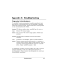
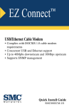
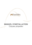
CE Mark Declaration of Conformance for EMI and Safety (EEC) This is to certify that this product complies with ISO/IEC Guide 22 and EN45014. It conforms to the following EMC specifications: EN55022(1988)/CISPR-22(1985) Class A EN60555-2(1995) Class A EN60555-3 IEC1000-4-2(1995) 4kV CD, 8kV AD IEC1000-4-3(1995) 3V/m IEC1000-4-4(1995) 1kV - (power line), 0.5kV - (signal line) IEC 1000-4-6(1995) 3Vrms This product complies with the requirements of the Low Voltage Directive 73/23/EEC and the EMC Directive 89/336/EEC. Warning! Do not plug a phone jack connector in the RJ-45 port. This may damage this device. Les raccordeurs ne sont pas utilisé pour le système téléphonique! VCCI Class A Compliance (Japan) Warranty Accton warrants to the original owner that the product delivered in this package will be free from defects in material and workmanship for the lifetime of the product. For the warranty to apply, you must register your purchase by returning the registration card indicating the date of purchase and including proof of purchase. There will be a minimal charge to replace consumable components, such as fuses, power transformers, and mechanical cooling devices. The warranty does not cover the product if it is damaged in the process of being installed. THE ABOVE WARRANTY IS IN LIEU OF ANY OTHER WARRANTY, WHETHER EXPRESS, IMPLIED OR STATUTORY, INCLUDING BUT NOT LIMITED TO ANY WARRANTY OF MERCHANTABILITY, FITNESS FOR A PARTICULAR PURPOSE, OR ANY WARRANTY ARISING OUT OF ANY PROPOSAL, SPECIFICATION OR SAMPLE. ACCTON SHALL NOT BE LIABLE FOR INCIDENTAL OR CONSEQUENTIAL DAMAGES. ACCTON NEITHER ASSUMES NOR AUTHORIZES ANY PERSON TO ASSUME FOR IT ANY OTHER LIABILITY. Copyright Copyright © 1997 by Accton Technology Corporation. All rights reserved. All trademarks or brand names are properties of their respective companies. Product specification are subject to change without notice. EM3554 E1297-R01 150826-101 EM3554 Slide-in Switch Modules Users Guide Warning: Optical Safety for Fiber Optic Modules The EM3554 Slide-in Modules The EM3554 Slide-in Modules are designed for use in Accton switch models which have a 4-port Fast Ethernet transceiver slot. At present, suitable units include the: CheetahSwich Workgroup (ES3508A) Caution: Do not install these modules in any other units. Contact your distributor for advice on newly released switches which may be designed for use with these modules. The EM3554 includes the following modules: EM3554-TX 4 10BASE-T/100BASE-TX (RJ-45) Ports EM3554-FX-SC 4 100BASE-FX (SC-Type) Ports EM3554-FX-ST 4 100BASE-FX (ST-Type) Ports Under normal conditions, the fiber optic transmit LED (Light Emmitting Diode) presents no hazard to your eyes. However, we recommend that you do not directly view the fiber TX port or fiber cable ends when the unit is powered on. Nor should you view the LED through a magnifying device when the unit is powered on. Handling the Module EM3554-TF-SC 2 10BASE-T/100BASE-TX (RJ-45) Ports and 2 100BASE-FX (SC-Type) Ports EM3554-TF-ST 2 10BASE-T/100BASE-TX (RJ-45) Ports and 2 100BASE-FX (ST-Type) Ports Caution: The EM3554 can easily be damaged by electrostatic discharge. To prevent electrostatic damage, observe the following guidelines: Do not remove the EM3554 from its packaging until you are ready to install it. These modules provide all the available ports for applicable units, and provide high-speed access to your network, or a direct connection to a local server or workstation. Do not touch any of the modules pins, connectors or components. Information about configuring these modules and advice about Fast Ethernet configuration rules can be found in the switchs user guide. Hold the module only by its edges or front panel. Wear an anti-static wristband connected to a suitable earth ground whenever handling the module. Store or transport these modules only in appropriate anti-static packaging. Safety Warning Before installing or removing the EM3554, first disconnect the switch from the main power supply. For full safety instructions, please refer to the user guide that accompanies the switch. Installing the EM3554 Making Twisted-Pair Connections Specifications 1 Ensure that the switch is disconnected from the main power supply, and you are wearing an anti-static wristband connected to a suitable earth ground. 1 2 Place the unit on a flat surface. Using a flathead screwdriver, remove the screws from the cover plate covering an empty slot on the front panel of the switch. 2 Power Consumption 12.5 Watts at 5 VDC Temperature 0°C to 40°C (32 to 104°F) Standard Operating Humidity 5% to 95% (Noncondensing) Standards IEEE 802.3, IEEE 802.3u ISO/lEC 8802-3 3 4 Keep the cover plate in a safe place. If you remove the module, replace the cover plate to prevent dust and debris from entering the unit and to maintain proper air flow. To make a direct connection to another compatible switch or repeater hub, connect the (RJ-45) MDI daisy-chain port on the module to an MDI-X port on the other device. When using the port with the selector switch, set it to MDI. Holding the module with the text on the front panel upright, slide it into the unit, ensuring that the edge connector is fully engaged. Be sure the front panel of the module is flush against the switch, and then attach it to the unit with the retainer screws attached to the face plate. Caution: Do not plug a phone jack connector into any RJ-45 port. This may damage the switch. Instead, use only twisted-pair cables with RJ-45 connectors that conform with FCC standards. Notes: When connecting to another switch or hub, you can also connect any MDI-X port on the module to an MDI port on the other device; or if an MDI port is not available, you can use crossover cabling and attach to MDI-X ports at both ends. Make sure each twisted-pair cable does not exceed 100 meters (328 feet). We advise using Category 5 cable for all network connections to avoid any confusion or inconvenience in the future when you upgrade attached devices to Fast Ethernet. Making Fiber Optic Connections 1 Remove the cover from the fiber connector on the EM3554. Keep it in a safe place, and place it back on the connector if you unplug the fiber cable from the module. 2 Plug the fiber connector on the cable into the fiber optic socket on the module. 3 Connect the other end of the cable to any device that has a standard 100BASE-FX Fast Ethernet fiber interface. Notes: A fiber optic cable cannot exceed 2 km (1.24 miles) at full duplex or 412 m (1351 ft) at half duplex. This maximum length may be less when connecting to a Fast Ethernet repeater. (Refer to the switchs user guide for more detailed information on cable length.) 4 Use the configuration method provided by your switch to match the communication mode of the attached device by setting the module to full or half duplex. Prepare 100W Category 3, 4 or 5 cable for standard 10 Mbps Ethernet connections, or 100W Category 5 cable for 100 Mbps Fast Ethernet connections. To connect to any device that uses a standard network interface such as a workstation or server, use the MDI-X (RJ-45) ports on the module. When using the port with the selector switch, set it to MDI-X. Putting the Switch Online 1 Power up the switch. 2 Check the LED indicators on the switch to ensure that the EM3554 is operating correctly. Refer to the switchs user guide for a description of the LED indications. Certification Emissions Immunity Safety CE Mark FCC Class A, VCCI Class A, CISPR Class A IEC 1000-4-2/3/4/6 UL, CSA, TÜV/GS EMI Certification EM3554 Slide-in Modules Troubleshooting If you experience any problems with the module, check the following items before contacting your distributor: Ensure the switch with the slide-in module is powered up. Ensure that the device attached to the module is powered up and operating correctly. Ensure that the module is properly seated in the slot. Verify that the ports are configured to match to the communication mode used by the attached device (full or half duplex, or autonegotiation for the RJ-45 ports). Check all connectors on both ends of the cables to be sure they are properly engaged. When inserting twisted-pair cable into an RJ-45 port, be sure the plug clicks into place to ensure that it is properly seated. If you are using fiber optic cable Try switching the TX and RX connections. Clean the cable plugs by wiping them gently with a clean tissue or cotton ball moistened with a little ethanol. Dirty fiber terminators on the fiber optic cables will impair the quality of the light transmitted through the cable. FCC Class A (USA) This equipment has been tested with a Class A computing device and has been found to comply with part 15 of FCC Rules. Operation in a residential area may cause unacceptable interference to radio and TV receptions requiring the operator to take whatever steps are necessary to correct the interference. You may use unshielded twisted-pair (UTP) for RJ-45 connections - Category 3 or greater for 10 Mbps connections, and Category 5 for 100 Mbps connections. Class A (Canada Department of Communications) This digital apparatus does not exceed the Class A limits for radio noise emissions from digital apparatus as set out in the interferencecausing equipment standard entitled "Digital Apparatus," ICES-003 of the Department of Communications. Cet appareil numérique respecte les limites de bruits radioélectriques applicables aux appareils numériques de Classe A prescrites dans la norme sur le matériel brouilleur: "Appareils Numérques," NMB-003 édictée par le ministère des Communications.