1
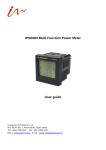
IPM3400 Compact Power Meter User guide IA Networks Technology Co., Ltd. 5F-1, No.44, Sec. 2, Roosevelt Rd., Taipei, Taiwan TEL:886-2-2395-3153 FAX:886-2-2395-3152 http:// www.iantech.com.tw E-mail:[email protected] IA Networks Technology IPM3400 User Guide Content Chapter 1 Introduction 1.1 Introduction 1.2 Caution 1.2.1 Danger 1.2.2 Products Warranty and Customer Support 1.2.3 Limitation of Warranty Chapter 2: Specification Chapter 3 : Installation 3.1 Inspection 3.2 safety 3.3 Size and Latch 3.4 Mounting and Dismounting 3.4.1 Mounting 3.4.2 Dismounting Chapter 4 : Wiring Diagrams 4.1 Connection Diagrams Chapter 5 : Dip switch On/Off Chapter 6: Communication Formats 6.1 Specification 6.2 Modbus Register Appendix : Question and Answer 3 IA Networks Technology IPM3400 User Guide Chapter 1 Introduction 1.1 Product Introduction IPM3400 series are designed for general single phase or poly phase power measurement, with wide range. it con be applied either on low voltage primary side or medium/high voltage secondary side for its high accuracy (<1%, IEC62053-21) under 5A current. IPM3400 equipped with clip-on CT, standard communication, small size and low cost. Features: 1. True RMS energy and power parameters measurement in compact size。 2. clip-on CT, easy wiring for on-line installation。 3. RS485 communication support Modbus protocol。 4. Wh accuracy better than 0.5%(pf =1)。 5. Support Lon Talks (option)。 6. wild range of measurement with various size of CT , up to 200A(24Φmm) 。 7. LED pulse output。 1.2 Caution 1.2.1 Danger The meter contains hazardous voltages. The meter should never be disassembled. Failure to observe this practice can result in serious injury or death. Any work on or near energized meters, meter sockets, or other metering equipment can present a danger of electrical shock. It is strongly recommended that all work should be performed only by qualified industrial electricians and metering specialist. IA Networks assumes no responsibility if your electrical installer does not follow the appropriate national and local electrical codes. 1.2.2 PRODUCT WARRANTY & CUSTOMER SUPPORT IA Networks warrants all products free from defects in material and workmanship for a period of one year from the date of shipping. During the warranty period, we will, at our position, either repair any product that proves to be defective. To report any defect, please contact :+886-2-23953153 or [email protected]. Please have the model, serial number and a detailed problem description available when you call. If the problem concerns a particular reading, please have all meter readings available. When returning any merchandise to IA Networks, a return SN. is required. 1.2.3 LIMITATION OF WARRANTY This warranty does not apply to defects resulting from unauthorized modification, misuse, or use for reason other than electrical power monitoring. The supplied meter is not a user-serviceable product. 4 IA Networks Technology IPM3400 User Guide Chapter 2 Specification Input V 10-300V Input I Aux Power Frequency Starting I Wiring diagram CT Φ10mm (60A) , CT Φ16mm(100A)、CT Φ24mm( 200A) DC 10-30V 60/50Hz <0.025A 1-phase 4-channel Power Parameters Measures Communication kWh Accuracy Size Operation Temp Installation V1, V1, V2, V2 I 1, I 2, I 3, I 4 kW1, kW2, kW3, kW4 kVA1, kVA2, kVA3, kVA4 kvar1, kvar2, kvar3, kvar4 PF1, PF2, PF3, PF4 kWh1, kWh2, kWh3, kWh4 kVAh1, kVAh2, kVAh3, kVAh4 kvarh1, kvarh2, kvarh3, kvarh4 Frequency RS485, half duplex isolated Baud Rate:9600, 19200(default), 38400 Protocol:Modbus LonTalks:(option) 0.5%(PF=1),better than IEC62053-21 78(L) × 35(W) × 99(H) mm -10℃~60 ℃ Rail-mounted 5 IA Networks Technology IPM3400 User Guide Chapter3: Installation 3.1 Inspection On receipt of the instrument and prior to installation, makes sure it has not been damaged during shipment. The instrument is no longer safe when, a) shows clear signs of damage b) does not work c) long storage under extreme conditions d) damage during shipment 3.2 Safety Please use the soft dry clothes to clean the instrument. Please do not use any chemical or detergent or volatile solvents to clean the instrument, in order to avoid any possibility of the cover damage。 3.3 Size and Latch Top View (mm) Side View (mm) Position of latch 6 IA Networks Technology IPM3400 User Guide Dimension of this product is 99mm(length)× 32mm(wide)× 78mm(high) Products come with external split type clip on CT’s. Use only the attached CT’s, and do not disconnect CT’s from meter. and never direct connect the other CT’s from the secondary side。 Please read this operation manual carefully before using。 Please re-confirm the measure position。 IPM3400 can be installed as rail mounting mode or embedded, no need to drill a hole or screw to fix it(rail mounting width can up to the length of 35 mm )。 Meter auxiliary power for IPM3400 is DC 10V -30V。 3.4 Mounting and Dismounting 3.4.1 Mounting Pull down the “latch” of meter, and mount the meter on to the rail and lock it, as shown in below picture. Pull down 3.4.2 Dismounting Wire Disconnection 1. Open the clicked CT first and remove CTS from lines,Do not disconnect CT from terminals. 2. Disconnect the voltage input wires from terminals and wrap the wire tips with plastic tape. 3. Disconnect the communication wires from terminal. 4. Disconnect the Aux power from terminal and wrap the wire tip with plastic tape. Dismount From the back to pull down the latch, then can release the meter 7 IA Networks Technology IPM3400 User Guide Chapter 4 : Wiring Diagrams Voltage Input This instrument can measure voltage up to a maximum 300V. Higher than 300V, please add the PT in front to protect the instrument. Confirm the voltage. Current Input The external CT’s are friable, please handle with care. The current input for this instrument is in mA range. Only the attached CT’s can be used. The normal CT’s from panel will damage the instrument due to its large current (around 5A) When more than one instrument will be installed, please do not disconnect the CT with its instrument. Each instrument is calibrated with matching CT’s. To install CT’s, confirm the lines with terminals and latch on the split CT with each cable. (Detail will be found in next section) CT bending area is quite frangible; please handle with extra care, especially when the room between CT’s is limited. The current direction must follow K-L marked on CT Please select the right size CT for different size current cables. The maximum current value can not exceed the CT rating. 8 IA Networks Technology IPM3400 User Guide 4.1 Connection diagram IPM3400 Please first check the current input terminal, and follow the white black, white black, white black, white black wired order(1S 1L 2S 2L 3S 3L 4S 4L).After connection the CT’s, clip on CT’s. Make sure the arrow sign on CT’s follow current flow direction(K→L)Note: it must in same direction。 Connect the voltage input terminal. For IPM3400, connect V2- V2+ and V1- V1+。 Then, Connect RS485 D+ D- ,LonTalks D+ D- (”-”, ”+” sequence base on the top cover mark showed)。And then, add the auxiliary power。DC10- 30V (+ - FG) 16Φ/100A 9 24Φ/200A IA Networks Technology 1S IPM3400 User Guide 1P4W(IPM3400) 1L 2S 2L 3S 3L 4S V2- 4L V2+ V1- L1 L1 L1 L2 L2 L2 L1 L1 L1 L2 L2 L2 V1+ Chapter 5 : Dip Switch ON /OFF Dip Switch Dip switch is used for Modbus address setting, default is 1 i.e. all OFF For example : Modbus address is 10,find the table of dip switch 1-6 is on, off, off, on, off, off SW1 -6 setting the Modbus address of communication, 1-64 Modbus Address 1 2 3 4 5 6 1 2 3 4 5 6 7 8 9 10 11 12 13 14 15 16 17 18 19 20 21 OFF ON OFF ON OFF ON OFF ON OFF ON OFF ON OFF ON OFF ON OFF ON OFF ON OFF OFF OFF ON ON OFF OFF ON ON OFF OFF ON ON OFF OFF ON ON OFF OFF ON ON OFF OFF OFF OFF OFF ON ON ON ON OFF OFF OFF OFF ON ON ON ON OFF OFF OFF OFF ON OFF OFF OFF OFF OFF OFF OFF OFF ON ON ON ON ON ON ON ON OFF OFF OFF OFF OFF OFF OFF OFF OFF OFF OFF OFF OFF OFF OFF OFF OFF OFF OFF OFF OFF ON ON ON ON ON OFF OFF OFF OFF OFF OFF OFF OFF OFF OFF OFF OFF OFF OFF OFF OFF OFF OFF OFF OFF OFF 10 IA Networks Technology 22 23 24 25 26 27 28 29 30 31 32 33 34 35 36 37 38 39 40 41 42 43 44 45 46 47 48 49 50 51 52 53 54 55 56 57 58 59 60 61 62 63 64 ON OFF ON OFF ON OFF ON OFF ON OFF ON OFF ON OFF ON OFF ON OFF ON OFF ON OFF ON OFF ON OFF ON OFF ON OFF ON OFF ON OFF ON OFF ON OFF ON OFF ON OFF ON OFF ON ON OFF OFF ON ON OFF OFF ON ON OFF OFF ON ON OFF OFF ON ON OFF OFF ON ON OFF OFF ON ON OFF OFF ON ON OFF OFF ON ON OFF OFF ON ON OFF OFF ON ON ON ON ON OFF OFF OFF OFF ON ON ON ON OFF OFF OFF OFF ON ON ON ON OFF OFF OFF OFF ON ON ON ON OFF OFF OFF OFF ON ON ON ON OFF OFF OFF OFF ON ON ON ON 11 IPM3400 User Guide OFF OFF OFF ON ON ON ON ON ON ON ON OFF OFF OFF OFF OFF OFF OFF OFF ON ON ON ON ON ON ON ON OFF OFF OFF OFF OFF OFF OFF OFF ON ON ON ON ON ON ON ON ON ON ON ON ON ON ON ON ON ON ON OFF OFF OFF OFF OFF OFF OFF OFF OFF OFF OFF OFF OFF OFF OFF OFF ON ON ON ON ON ON ON ON ON ON ON ON ON ON ON ON OFF OFF OFF OFF OFF OFF OFF OFF OFF OFF OFF ON ON ON ON ON ON ON ON ON ON ON ON ON ON ON ON ON ON ON ON ON ON ON ON ON ON ON ON ON ON ON ON IA Networks Technology IPM3400 User Guide SW7-8 are used to select Wh pulse output (IPM3400) to the LED for each of four channels IPM3400:Select Wh pulse output to LED Wh pulse output 7 8 Wh1(ch1) Wh2(ch2) Wh3(ch3) Wh4(ch4) OFF ON OFF ON OFF OFF ON ON 12 IA Networks Technology IPM3400 User Guide Chapter 6 communication Formats 6.1 Specifications Communication protocol :Modbus Transport specification Bits per Byte:1 start bit 8 data bits, least significant bit sent first 1 or 2 stop bits(default = 1, stop) Error Check:Cyclical Redundancy Check(CRC) Baud Rate:9600, 19200(default), 38400 Modbus slave address:1-64(default:1) Modbus Function Code:03h, 04h, 10h Code MODBUS_ name Description 03h Read Holding Registers Read the contents of read/write location 04h Read Input Registers Read the contents of read only location 10h Pre-set Multiple Registers Set the contents of read/write location Note: the max. data reading of Function 03 and Function04 is 125 registers Format of data Integer: 16 bits with sign Unsigned Integer:16 bits without sign Float:IEEE 754 Format ,each with 2 registers, Low Word is first priority while transmit IEEE 754 Format Definition of the floating format of the Bits Data Hi Word, Data Hi Word, Data Lo Word, Data Lo Word, Hi Byte Lo Byte Hi Byte Lo Byte SEEE EEEE EMMM MMMM MMMM MMMM MMMM MMMM Value = (-1)S2E - 127(1.M) 0 < E < 255 Where: S represents the sign bit where 1 is negative and 0 is positive E is the two’s complement exponent with an offset of 127. i.e. an exponent of zero is represented by 127, an exponent of 1 by 128 etc. M is the 23-bit normal mantissa. The highest bit is always 1 and, therefore, is not stored. transport sequence 1 2 3 4 Data Lo Word,Hi Byte Data Lo Word,Lo Byte Data Hi Word,Hi Byte Data Hi Word,Lo Byte 13 IA Networks Technology IPM3400 User Guide 6.2 Modbus Register Modbus Module #1 Holding Register : Setup Parameter Modbus Register Len Data Type 0x1000 Word UInt 44098 0x1001 Word UInt Meter_Ratio 44099 0x1002 Word UInt 0: 9600 1: 19200 2: 38400 0:1 Stop bit, 1:2 Stop bit 1-65535 PT_Ratio 44100 0x1003 Word UInt 1-65535 Parameter name Modicom Format Hex Comm_485_BaudRate 44097 Comm_485_StopBit CT_Ratio 44101 0x1004 Word Range UInt 1-65535 Default value Units 1 bps Comment 0 500 100 0.01 10 0.1 0.01-655.35 (V1.26) 0.1-6553.5 (V1.00~V1.25) 1 Modbus Module #2 Input Register : Voltage, Current, Power, Energy(Float) for IPM3400 Parameter name V_a I_a kW_a kvar_a kVA_a PF_a kWh_a kvarh_a kVAh_a V_b I_b kW_b kvar_b kVA_b PF_b kWh_b kvarh_b kVAh_b V_c I_c kW_c kvar_c Modbus Register Modicom Hex Format 343530x110034354 0x1101 343550x110234356 0x1103 343570x110434358 0x1105 343590x110634360 0x1107 343610x110834362 0x1109 343630x110A34364 0x110B 343650x110C34366 0x110D 343670x110E34368 0x110F 343690x111034370 0x1111 343710x111234372 0x1113 343730x111434374 0x1115 343750x111634376 0x1117 343770x111834378 0x1119 343790x111A34380 0x111B 343810x111C34382 0x111D 343830x111E34384 0x111F 343850x112034386 0x1121 343870x112234388 0x1123 343890x112434390 0x1125 343910x112634392 0x1127 343930x112834394 0x1129 343950x112A- Len Data Type DWord Units Comment Float Volt Primary DWord Float Amp Primary DWord Float kW Primary DWord Float kvar Primary DWord Float kVA Primary DWord Float Primary DWord Float Primary DWord Float Primary DWord Float Primary DWord Float Volt Primary DWord Float Amp Primary DWord Float kW Primary DWord Float kvar DWord Float kVA DWord Float DWord Float DWord Float DWord Float Dword Float Volt Dword Float Amp Dword Float kW Dword Float kvar 14 Range Primary Primary Primary Primary Primary Primary Primary Primary Primary IA Networks Technology kVA_c PF_c kWh_c kvarh_c kVAh_c V_avg(V_d) I_avg(I_d) kW_tot(kW_d) kvar_tot(kvar_d) kVA_tot(kVA_d) PF_tot(PF_d) kWh_tot(kWh_d) kvarh_tot(kvarh_d) kVAh_tot(kVAh_d) Frequency 34396 3439734398 3439934400 3440134402 3440334404 3440534406 3440734408 3440934410 3441134412 3441334414 3441534416 3441734418 3441934420 3442134422 3442334424 3442534426 0x112B 0x112C0x112D 0x112E0x112F 0x11300x1131 0x11320x1133 0x11340x1135 0x11360x1137 0x11380x1139 0x113A0x113B 0x113C0x113D 0x113E0x113F 0x11400x1141 0x11420x1143 0x11440x1145 0x11460x1147 0x11480x1149 IPM3400 User Guide Dword Float kVA Dword Float Dword Float Dword Float Dword Float Volt Dword Float Amp Dword Float kW Dword Float kvar Dword Float kVA Dword Float Dword Float Dword Float Dword Float Dword Float Primary Primary Primary Primary Primary Primary Primary Primary Primary Primary Hz After V1.29-3 Modbus Module #4 Input Register : Voltage, Current, Power, Energy(Int) for IPM3400 Parameter name V_a I_a kW_a kvar_a kVA_a PF_a kWh_a kvarh_a kVAh_a V_b I_b kW_b kvar_b kVA_b Modbus Register Modicom Hex Format 346090x120034610 0x1201 346110x120234612 0x1203 346130x120434614 0x1205 346150x120634616 0x1207 346170x120834618 0x1209 34619 0x120A 3462034621 3462234623 3462434625 3462634627 3462834629 3463034631 3463234633 3463434635 0x120B0x120C 0x120D0x120E 0x120F0x1210 0x12110x1212 0x12130x1214 0x12150x1216 0x12170x1218 0x12190x121A Len Data Type DWord Range Units Comment UInt32 0.1 Volt Primary DWord UInt32 0.1A Primary DWord Int32 0.1kW Primary DWord Int32 0.1kvar Primary DWord Int32 0.1kVA Primary Word Int -1000~+1000 0.001PF -1.000~1.000 DWord Int32 0~99999999 0.1kWh 0~9999999.9 DWord Int32 0~99999999 0.1kvarh 0~9999999.9 DWord Int32 0~99999999 0.1kVAh 0~9999999.9 DWord UInt32 0.1 Volt Primary DWord UInt32 0.1A Primary DWord Int32 0.1kW Primary DWord Int32 0.1kvar Primary DWord Int32 0.1kVA Primary PF_b 34636 0x121B Word Int -1000~+1000 0.001PF -1.000~1.000 kWh_b 3463734638 0x121C0x121D DWord Int32 0~99999999 0.1kWh 0~9999999.9 kvarh_b 34639- 0x121E- DWord Int32 0~99999999 0.1kvarh 0~9999999.9 15 IA Networks Technology kVAh_b V_c I_c kW_c kvar_c kVA_c PF_c kWh_c kvarh_c kVAh_c V_avg(V_d) I_avg(I_d) kW_tot(kW_d) kvar_tot(kvar_d) kVA_tot(kVA_d) PF_tot(PF_d) kWh_tot(kWh_d) kvarh_tot(kvarh_d) kVAh_tot(kVAh_d) Frequency 34640 3464134642 3464334644 3464534646 3464734648 3464934650 3465134652 0x121F 0x12200x1221 0x12220x1223 0x12240x1225 0x12260x1227 0x12280x1229 0x122A0x122B 34653 0x122C 3465434655 3465634657 3465834659 3466034661 3466234663 3466434665 3466634667 3466834669 0x122D0x122E 0x122F0x1230 0x12310x1232 0x12330x1234 0x12350x1236 0x12370x1238 0x12390x123A 0x123B0x123C 34670 0x123D 3467134672 3467334674 3467534676 0x123E0x123F 0x12400x1241 0x12420x1243 34677 0x1244 IPM3400 User Guide DWord Int32 DWord 0~99999999 0.1kVAh 0~9999999.9 UInt32 0.1 Volt Primary DWord UInt32 0.1A Primary DWord Int32 0.1kW Primary DWord Int32 0.1kvar Primary DWord Int32 0.1kVA Primary Word Int -1000~+1000 0.001PF -1.000~1.000 DWord Int32 0~99999999 0.1kWh 0~9999999.9 DWord Int32 0~99999999 0.1kvarh 0~9999999.9 DWord Int32 0~99999999 0.1kVAh 0~9999999.9 DWord UInt32 0.1 Volt Primary DWord UInt32 0.1A Primary DWord Int32 0.1kW Primary DWord Int32 0.1kvar Primary DWord Int32 0.1kVA Primary Word Int -1000~+1000 0.001PF -1.000~1.000 DWord Int32 0~99999999 0.1kWh 0~9999999.9 DWord Int32 0~99999999 0.1kvarh 0~9999999.9 DWord Int32 0~99999999 0.1kVAh 0~9999999.9 Word UInt16 0~9999 0.01Hz 0.00~99.99 After V1.29-3 Appendix:Question and Answer Q1. if the turn point of the split type clip on CT break, or inner iron -core break, how to settle this condition? (1)the measure data will be not accuracy as before, and can not use again。 (2)please do not use the tape to fix it and then re-use again。 Q2. if multiple set of meter are being installed,the split type clip on CT and set of meter are able to take it apart and to mix use? Please do not mix use,because the set of ct and meter from IA Networks, are all calibrate well and Gain after QC。 16 IA Networks Technology IPM3400 User Guide Q3. the real power rate(kw), if the value of measure is negative? (1)first check the current input end – line terminal, (check the connect is it 1S、1L、2S、2L、3S、 3L、4S、4L) ,base on white black, white black, white black follow the sequence order。 (2)check the field current is same direction of(K→L)must follow the same direction on the split type clip on CT inner arrow。 Q4. PC and meter can not make the communication? (1)confirm the Modbus Address,default is 1。 (2)confirm the Band Rate,default is 9600。 (3)confirm the stop bit,default is 2。 (4)confirm the RS485 之 connect line terminal +、-is it connect correct。 Q5. Regarding to the combine shipment of the meter with split type CT, what is the maximum dimension? (1)power line if <Φ10 use 60A CT,Φ10~Φ16 use 100A CT,Φ16~Φ24 use 200A CT。 Q6. Regarding to the split type small CT , if the wire is not longer enough ? (1)Φ10split type CT,fix wire is 1.8M,if need extension, please use the same size wire, and dimension to apply it,the connection part is need to use tinning and insulate tape to cover it the copper。 (2)Φ16and Φ24split type CT,the std. wire of length is 2M, if over 2M you can choice the suitable one to add。 17