1
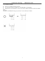
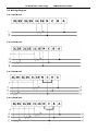
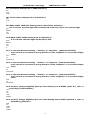
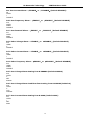
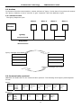
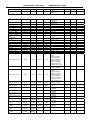
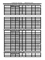
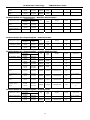
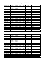
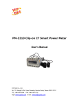
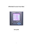
IPM3300 Multi-Function Power Meter User guide IA Networks Technology Co., Ltd. 5F-1, No.44, Sec. 2, Roosevelt Rd., Taipei, Taiwan TEL:886-2-2395-3153 FAX:886-2-2395-3152 http:// www.iantech.com.tw E-mail:[email protected] IA Networks Technology IPM3300 User Guide Content Chapter 1 Introduction 1.1 Product Introduction 1.2 Caution 1.2.1 Danger 1.2.2 PRODUCT WARRANTY & CUSTOMER SUPPORT 1.2.3 LIMITATION OF WARRANTY 1.3 Specification Chapter 2 Installation 2.1 Safety 2.2 Mounting 2.2.1 Size and Latch Chapter 3 Connection 3.1 Back view of connect port 3.1.1 Aux. Power Supply 3.1.2 Digital Output 3.1.3 Current Terminal 3.1.4 Voltage Terminal 3.2 Wiring diagram 3.2.1 1P2W/1CT 3.2.2 1P3W/2CT 3.2.3 3P3W/2CT 3.2.4 3P3W/3CT 3.2.5 3P4W/3CT Chapter 4 Display and setup 4.1 Display 4.2 Operation 4.2.1「M」Button 4.2.2 「P」Button 4.2.3「E/T」Button 4.2.4 「V/A」button 4.3 Setting「M」、「P」、「E/T」and「V/A」 4.3.1 General Setting (N) 4.3.2 Clear Setting (C) 4.3.3 Alarm Setting (A) Chapter 5 Communication format 5.1 RS485 5.1.1 RS485 standard 5.1.2 Wiring for instruments communication 5.2 Modbus 5.2.1 Modbus Format 5.3 Communication protocol 5.4 IEEE 754 Format 5.5 Modbus RTU Mode 5.6 Modbus Function Code 5.7 IPM3300 Parameter 1 IA Networks Technology IPM3300 User Guide Chapter 1 Product Introduction 1.1 IPM3300 Introduction IPM3300 is designed for single and three phase power monitoring and measurement. It provides wide rang of measurements including current, voltage, energy, watt, power factor, watt-hour, frequency…etc. Product Features: Comply IEC62053-22 Class 0.5 standard V、I accuracy <0.2%, Wh<0.5%, with bi-directional energy measurement More than 90 parameters measure Current direction setting to correct the display value Large size of LCD with backlight adjustment in 4-stage, easy to operate Power Quality measurement in V/I unbalance、V Eligibility、Min.& Max. parameters Compact size, standard DIN 96*96, equipped with four clips to tight the meter on the sheet metal With RS485 communication protocol 1.2 Caution 1.2.1 Danger The meter contains hazardous voltages. The meter should never be disassembled. Failure to observe this practice can result in serious injury or death. Any work on or near energized meters, meter sockets, or other metering equipment can present a danger of electrical shock. It is strongly recommended that all work should be performed only by qualified industrial electricians and metering specialist. IA networks Corporation assumes no responsibility if your electrical installer does not follow the appropriate national and local electrical codes. 1.2.2 PRODUCT WARRANTY & CUSTOMER SUPPORT IA Networks Corporation warrants all products free from defects in material and workmanship for a period of one year from the date of shipping. During the warranty period, we will, at our position, either repair any product that proves to be defective. To report any defect, please contact : +886-2-2395-3153 or [email protected] Please have the model, serial number and a detailed problem description available when you call. If the problem concerns a particular reading, please have all meter readings available. When returning any merchandise to IA Networks Corporation a return SN. is required. 1.2.3 LIMITATION OF WARRANTY This warranty does not apply to defects resulting from unauthorized modification, misuse, or use for reason other than electrical power monitoring. The supplied meter is not a user-serviceable product. 2 IA Networks Technology IPM3300 User Guide 1.3 Product Spec. Aux Power Input Voltage Input Current Accuracy Frequency Measures Alarms Power Quality Display Communication Timer Wiring Ports I/O Operation Temperature Storage Temperature Humidity Dust/Water Proof Rating Size Power consumption Environmental Conditions AC80-264V/DC100-300V, Max.2.3W CATII 10V-600V L-L* 2mA-5A V、I 0.2%, W 0.5% (PF=1.0) 45-65Hz V, I, kW, kvar, kVA, kWh, kvarh, kVAh PF, Frequency, Demand, Running hour NONE、OVER V/I、OVER F; UNDER V /I、UNDER F; OVER Dmd; ANY V/I unbalance、V Eligibility、Min.& Max. parameters Mono 68X59 LCD RS485*1, LonTalk(option) RTC Aux Power、Voltage、Current、DO*2、RS485、LON DO OUTPUT*2;DO1 Alarm output、DO2 Pulse/ Alarm output -20℃-70℃ -25℃-80℃ 20-90%RH Panel:IP52,Case:IP20 96(W) × 96(H) × 97(L) mm 0.45~0.7W (Backlight off) 1.3~1.7W (Max. ,Backlight) 2.3W (Max. Backlight & Lon module) Indoor use Altitude up to 2000M Transient overvoltage on the mains supply is 2500V Pollution degree:2 *CATII-Is for measurement performed on circuits directly connected to the low voltage installation 3 IA Networks Technology IPM3300 User Guide Chapter 2 Installation 2.1 Safety On receipt of the instrument and prior to installation, makes sure it has not been damaged during shipment. The instrument is no longer safe when, a) Shows clear signs of damage b) Does not work c) Long storage under extreme conditions d) Damage during shipment 2.2 Mounting This instrument should install on vibration free switchboard and with environment temperature between -20℃~70℃, humility between 20-90%RH(no condensing) For the instrument is already equipped with an internal protection fuse, a 1AmAT HBC fuse is still recommended during installation Prior to maintain/repair this instrument, always disconnect this instrument from all power sources Only have qualified and authorized personnel to carry out installation, maintenance and repair Water proof for front panel IP52, case IP20 2.2.1 Size and Latch Front View(mm) Back View (mm) Side View(mm) After mounting the instrument, place all four support latch in position. Panel cut-out area is 91.5x91.5mm (+/-0.5mm) 4 IA Networks Technology IPM3300 User Guide Chapter 3 Connection 3.1 Back view of connect port 1 2 4 3 5 6 1.Aux Power(N-, ,L+) 2.Digital output (Com2 DO2 Com1 DO1) 3.Current Terminal (3L 3S 2L 2S 1L 1S) 4.Lon Port(D-,D+) 5.Voltage Terminal (N,C,B,A) 6.RS485 Port (D-,COM,D+) 3.1.1 Aux. Power Supply Before powering the instrument, verify the pin position at L and N, leave the middle pin blank. Power standard is 80-264Vac/100-300Vdc. An internal protection fuse 250V, 1A is equipped. The instrument Aux. power must not be earthed. 3.1.2 Digital Output 2 channel 4 pin digital output (Com2 DO2 Com1 DO1) 12-240VAC-DC/120mA max Com1 DO1 for digital output1, Com2 DO2 for digital output 2 Port 1 assign selection : NONE、OVER V/I、OVER F; UNDER V /I、UNDER F; OVER Dmd; ANY。 Port 2 assign selection : Energy pulse output base on kh(wh/ pulse) setting or alarm output same as port 1 3.1.3 Current Terminal The current input are 3 channels/6 terminals(3L 3S 2L 2S 1L 1S) Input current range from 2mA to 5A (CT secondary) Warning ! The CT input current must not exceed 10A Warning ! Be sure to short secondary’s of each current transformer, before removing the CT connection inputs. 5 IA Networks Technology IPM3300 User Guide 3.1.4 Voltage Terminal There are 4 voltage terminals (N.C.B.A) 。 The instrument measure voltage from 10V-600V RMS.(PT secondary) Voltage must not exceed 600V, in case of over 600V, voltage transformer need to be applied. Note ! 3P3W/2CT and 3P3W/3CT wiring, only connect “C A N”, and leave “B” blank 6 IA Networks Technology IPM3300 User Guide 3.2 Wiring diagram 3.2.1 1P2W/1CT 3.2.2 1P3W/2CT 3.2.3 3P3W/2CT 3.2.4 3P3W/3CT 7 IA Networks Technology IPM3300 User Guide 3.2.5 3P4W/3CT 8 IA Networks Technology IPM3300 User Guide Chapter 4 Operation & Setting 4.1 Display The IPM3300 is equipped with a large back-lit LCD and 4 function buttons. It shows up to five measurements simultaneously. 1 3 9 4 5 11 10 6 7 13 8 2 12 Item 1 2 3 4 5 6 7 8 9 10 11 12 13 Display Content Values, for V,I,KW……Demand, eligibility rate and unbalance rate Values, for energy & time Load percentages Unbalance rate indicator Types of measurement (I,U,E,P….) Alarm buzzer on/off Indicator for time display in zone 2 Indicator for energy display in zone 2 Indicator for pulse output and communication Display for power factor and load characteristics Units for measurements Function Buttons, “M” “P” “E/T” “V/A” DO1, DO2 Status ***THD、DI、DO3、DO4:To be available in near future 9 IA Networks Technology IPM3300 User Guide 4.2 Operation The IPM3300 equipped with function buttons to easily view all values and modify device setting. From left to right, there are「M」 、「P」 、「E/T」and「V/A」respectively. Button「M」to display maximum and minimum values Button 「P」 to display power for each phase and total , power factor (PF), frequency (F) and power demand. Button「E/T」to display Energy、RTC and running hour Button「V/A」to display Voltage and Current 4.2.1「M」Button Press successively to present the maximum minimum and average values of present measure parameters. For example, if IPM3300 is currently display “Voltage” with “U” shown on the left middle of the screen, press “M” Button will show the Max./Min. and average values of Voltages. The following lists all the values that can be shown for Max./Min. and average values depending on the display parameters which are showing now Max./Min. Voltage(L-L,L-N,Average) Max./Min. Current(Per phase,Average) 「V/A」button then「M」button Max./Min. Voltage & Current unbalance rate Max./Min. kW(Per phase,Total) Max./Min. kvar (Per phase,Total) Max./Min. kVA (Per phase,Total) 「P」button then「M」button Max./Min. kW-t, kVA-t, kvar-t Min. PF Max./Min. Frequency Max. Power Demand 4.2.2 「P」Button 「P」Button is for power selection. Press「P」Button successively to obtain: Active power (P) per phase and total Reactive power (Q) per phase and total Apparent power (S) per phase and total Total active power (P), reactive power (Q) , apparent power (S) and power factor(PF) Total active power (P), reactive power (Q) , apparent power (S) and frequency(F) Previous power demand kW, , demand subinterval remain time (sec) and current power demand kW 4.2.3「E/T」Button 「E/T」Button is for Energy & Time. Press「E/T」successively to obtain the following values in the zone 8 (bottom lane of the screen) Total active energy (kWh-t) Total reactive energy (kvarh-t) Total apprerant energy (kVAh-t) Total meter running hours (Total) Total meter running hours with load (Net) Year-Month-Day Hr-Min-Sec. 4.2.4 「V/A」button 「V/A」button is for showing the Voltage and Current. Press button successively to obtain Phase to phase voltages and average (U) Phase to neutral voltages and average (U) Instantaneous current (I) Unbalance rate for voltages and current Voltage eligibility rate 10 IA Networks Technology IPM3300 User Guide 4.3 Setting「M」、「P」、「E/T」and「V/A」 To enter setting mode, press「M」and 「V/A」buttons simultaneously. The setting mode is used for: basic operation, clear informal data and alarms setting 「M」to move cursor right ward like「」 「P」to move the cursor down ward like「」or 「reduce one」 「E/T」to move the cursor up ward like「」or 「add one」 「V/A」to confirm the selection like「Enter」, and turn to next page 「M」and「V/A」together to move back like「ESC」or back to operation display First, to press「M」a「V/A」simultaneously to enter password entering page, it required 4 digits (default is 0000). PASS WORD 0000 Then, select the setting from「BASIC」 、「ALARM+I/O」、 「CLEAR」by used「P」or「E/T」 P0 MAIN MENU BASIC / ALARM+I/O / CLEAR 4.3.1 General Setting (N) N1: Address Setting from 1-255 (Default 15) N1 Add 015 N2: BAUD RATE Setting - 4800, 9600, 19200, 38400, 57600. (Default 19200) N2 BAUD RATE 19200 N3: STOP BIT Setting - “1” or “2” (Default 1) N3 STOP BIT 1 N4: Wire Type Setting -1P2W,1P3W,3P3W-2CT,3P3W-3CT,3P4W-Y,AUTO (Default AUTO) N4 WIRE TYPE 3P4W N5: PT Primary Setting from 60-600000 (Default 110) N5 PT1 000110 N6: PT2 Secondary Setting from 1-600 (Default 110) N6 PT2 110 11 IA Networks Technology IPM3300 User Guide N7: CT Primary Setting from 1-5000 (Default 1) N7 CT1 0001 N8: CT Secondary Setting from 1-5 (Default 1) N8 CT2 1 N9: BACK LIGHT TIME OUT Setting from 0-120 minutes (Default 1) . If 0 is chosen, the back light will be always ON. Enter any key to turn on back light. N9 BACK LIT 120 N10: BACK LIGHT LEVEL Setting from 0-4 (Default 3). If 0 is chosen, the back light will be always OFF. N10 BACK LIT LVL 3 N11: I-1 Current Direction Setting - “Positive” or “Negative”. (Default POSITIVE). If the current is connected in wrong direction, select “Negative” to correct the display value. N11 I-1 POSITIV E N12: I-2 Current Direction setting - “Positive” or “Negative”. (Default POSITIVE). If the current is connected in wrong direction, select “Negative” to correct the display value. N12 I-2 POSITIVE N13: I-3 Current Direction setting - “Positive” or “Negative”. (Default POSITIVE). If the current is connected in wrong direction, select “Negative” to correct the display value. N13 I-3 POSITIVE N14: V1(V12) Voltage Eligibility Rate Up Limit Setting from 0-65535 (Scale 0.1, refer to Secondary) (Default 65535) N14 U1 UP LMT 65535 N15: V1(V12) Voltage Eligibility Rate Low Limit Setting from 0-65535 (Scale 0.1, refer to Secondary) (Default 0) N15 U1 LOW LMT 00000 12 IA Networks Technology IPM3300 User Guide N16: V2(V23) Voltage Eligibility Rate Up Limit Setting from 0-65535 (Scale 0.1, refer to Secondary) (Default 65535) N16 U2 UP LMT 65535 N17: V2 (V23) Voltage Eligibility Rate Low Limit Setting from 0-65535 (Scale 0.1, refer to Secondary) (Default 0) N17 U2 LOW LMT 00000 N18: V3 (V31) Voltage Eligibility Rate Up Limit Setting from 0-65535 (Scale 0.1, refer to Secondary) (Default 65535) N18 U3 UP LMT 65535 N19: V3 (V31) Voltage Eligibility Rate Low Limit Setting from 0-65535 (Scale 0.1, refer to Secondary) (Default 0) N19 U3 LOW LMT 00000 N20: Demand Mode Setting -「BLOCK」or「ROLLING」(Default BLOCK) N20 DMD MODE BLOCK N21: Sub-Interval Number Setting - 1,2,3,4,5,6,10, only used for “Rolling Mode” (Default 1) N21 SUB INTV NUM 1 N22: Sub-Interval Length (Time) Setting - 1,2,3,4,5,6,10,12,15,30,60 min. (Default 15) N22 SUB INTV LENG 15 N23: Date Setting N23 DATE 2009.02.20 13 IA Networks Technology IPM3300 User Guide N24: Time Setting N24 TIME 00:00:00 N25: Password Setting-four digits from 0000-FFFF (Default 0000) N25 PASS WORD 0000 4.3.2 Clear Setting (C) C1: Energy Reset – Yes or No C1 ENRG RST NO C2: Reset All – Yes or No C2 RST ALL NO C3: Reset OF Total Meter Run Hour – Yes or No C3 RST R-HR TOT NO C4: Reset OF Net Load Run Hour – Yes or No C4 RST R-HR NET NO C5: Demand Reset – Yes or No C5 RST DMD NO C6: Reset of Max and Min values – Yes or No C6 RST MAX MIN NO C7: Reset to Default - Yes or No C7 RST DEFT NO 14 IA Networks Technology IPM3300 User Guide C8: Reset Voltage Eligibility Rate – Yes or No C8 RST VER NO 4.3.3 Alarm Setting (A) A1: Enable Alarm – On or Off (Default OFF) A1 ALRM OFF A2: Enable Buzzer – On or Off (Default OFF) A2 BUZZ OFF A3: DO1 can be assigned as the alarm output, and can be selected from「None」 、 「Any」 、 「Over V」、「Over I」、「Over F」、「Over Dmd」、「Over V」、 「Under I」、「Under F」(Default None) A3 DO1 ALRM NONE A4: DO2 can be assigned to output「PULSE」or「ALARM」(Default PULSE) A4 DO2 OUT PUT PULSE /ALARM A5: If DO2 is assigned to「ALARM」 , then select from 「None」 、「Any」、 「Over V」、 「Over I」、 「Over F」 、「Over Dmd」、「Over V」、「Under I」、「Under F」(Default None) A5 DO2 ALRM NONE A6: If DO2 is assigned to「PULSE」, then select from「NONE」 、 「kWh」 、 「kvarh」 、 「kVAh」(Default NONE) A6 PULS OUT PUT NONE A7: If DO2 is assigned to「PULSE」, pulse rate can be 1 to 6000, 1 stand for 0.1kwh/pulse (Default 10) A7 kh 0001 A8: Over Voltage Alarm – 「ENABLE」or 「DISABLE」(Default DISABLE) A8 OVER V DISABLE 15 IA Networks Technology IPM3300 User Guide A9: Over Current Alarm –「ENABLE」or 「DISABLE」(Default DISABLE) A9 OVER I DISABLE A10: Over Frequency Alarm –「ENABLE」or 「DISABLE」(Default DISABLE) A10 OVER FREQ DISABLE A11: Over Demand Alarm –「ENABLE」or 「DISABLE」(Default DISABLE) A11 OVER DMD DISABLE A12: Under Voltage Alarm –「ENABLE」or 「DISABLE」(Default DISABLE) A12 UNDE V DISABLE A13: Under Current Alarm –「ENABLE」or 「DISABLE」(Default DISABLE) A13 UNDE I DISABLE A14: Under Frequency Alarm –「ENABLE」or 「DISABLE」(Default DISABLE) A14 UNDE FREQ DISABLE A15: Over Voltage Alarm Setting from 0-600000 (Default 600000) A15 OVER V SET 600000 A16: Over Voltage Alarm Condition Clear Setting from 0-600000 (Default 0) A16 OVER V CLR 0000000 A17: Over Current Alarm Setting from 0-9999 (Default 9999) A17 OVER I SET 9999 16 IA Networks Technology IPM3300 User Guide A18: Over Current Alarm Condition Clear Setting from 0-9999 (Default 0) A18 OVER I CLR 0000 A19: Over Frequency Alarm Setting from 45-65 (Default 65) A19 OVER FREQ SET 63 A20: Over Frequency Alarm Condition Clear Setting from 45-65 (Default 45) A20 OVER FREQ CLR 43 A21: Over Demand Alarm Setting from 0-65535 kW (Default 65535) A21 OVER DMD SET 65535 A22: Over Demand Alarm Condition Clear Setting from 0-65535 kW (Default 0) A22 OVER DMD CLR 00000 A23: Under Voltage Alarm Setting from 0-600000 (Default 0) A23 UNDE V SET 000000 A24: Under Voltage Alarm Condition Clear Setting from 0-600000 (Default 600000) A24 UNDE V CLR 600000 A25: Under Current Alarm Setting from 0-9999 (Default 0) A25 UNDE I SET 0000 A26: Under Current Alarm Condition Clear Setting from 0-9999 (Default 9999) A26 UNDE I CLR 9999 17 IA Networks Technology IPM3300 User Guide A27: Under Frequency Alarm Setting from 45-65 (Default 45) A27 UNDE FREQ SET 45 A28: Under Frequency Alarm Condition Clear Setting from 45-65 (Default 65) A28 UNDE FREQ CLR 65 18 IA Networks Technology IPM3300 User Guide Chapter 5 Communication 5.1 RS485 5.1.1 RS485 standard PARAMETERS Mode of Operation Number of Drivers and Receives Maximum cable length( meters) Maximum data rate ( baud ) Maximum common mode voltage ( Volts ) Maximum Driver Output Levels ( Loaded ) Maximum Driver Output Levels ( Unloaded ) Drive Load ( Ohms) Driver Output short circuit Resistance ( kohms) Minimum receiver input Resistance ( kohms) Receiver sensitivity Differential 32 Drivers / 32 Receivers 1200 10M 12 to -7 +/- 1.5 +/- 6 60( min ) 150 to Gnd, 250 to -7 or 12V 12 +/- 200mv 5.1.2 Wiring for instruments communication RS485communication must used twisted paired wire, as show in the following program. “D+” connect to one wire and “D-” to the other one Master DD+ Slave D- Slave D+ D- D+ Slave D- D+ 120 ohm 120 ohm Cautions : There must be no more than two wires connected to each terminal, this ensures that a “Daisy Chain” or “Straight Line” configuration is used. A “star” or a network with “Stubs(Tees)” is not recommended as reflections within the cable may result in data corruption。 19 IA Networks Technology IPM3300 User Guide 5.2 Modbus In the start of modus communication, master will issue a “Query” to the slave. Every slave will monitor the “Query” address, so as to “execute’ or give “response” when the address is right 5.2.1 Modbus Format The Query-Response Cycle Slave 1 Slave 2 Slave 3 Slave n Master Query Response Query message from Master Device Address Device Address Function Code Function Code 8 bit Data Bytes 8 bit Data Bytes Error Check Error Check Response messages from Slave 5.3 Communication protocol IPM3300 use Modus RTU as the communication protocol. The following shows Query and Response format. Query: Slave Address Function Code 0x03, 0x04 Response: Slave Function Addre Code ss 0x03, 0x04 Start Address (Hi) Byte Count Start Address (Lo) Data (Hi) Number of Points (Hi) Data (Lo) Number of Points (Lo) Error Check (Lo) 20 Error Check (Lo) Error Check (Hi) Error Check (Hi) IA Networks Technology Query: Slav e Addr ess Functio n Code 0x10 Start Addres s (Hi) Response: Slave Function Address Code 0x10 Start Address (Lo) Start Address (Hi) Number of Points (Hi) Start Address (Lo) IPM3300 User Guide Number of Points (Lo) Number of Points (Hi) Byte Count Number of Points (Lo) Data (Hi) Data (Lo) Error Check (Lo) Error Check (Lo) Error Check (Hi) Error Check (Hi) 5.4 IEEE 754 Format The bits in an IEEE 754 format have the following significance: Data Hi Word, Data Hi Word, Data Lo Word, Data Lo Word, Hi Byte Lo Byte Hi Byte Lo Byte SEEE EEEE EMMM MMMM MMMM MMMM MMMM MMMM Where: S represents the sign bit where 1 is negative and 0 is positive E is the two’s complement exponent with an offset of 127, i.e. an exponent of zero is represented by 127, an exponent of 1 by 128 etc. M is the 23-bit normal mantissa. The highest bit is always 1 and, therefore, is not stored. For each floating point value requested two Modbus registers or points (four bytes) must be requested. The received order and significance of these four bytes for the Integral products is shown below: Data Lo Word, Data Lo Word, Data Hi Word, Data Hi Word, Hi Byte Lo Byte Hi Byte Lo Byte 5.5 Modbus RTU Mode Since Controllers can be setup to communicate on standard Modbus networks using either of two transmission modes:ASCII or RTU. IPM3300 uses RTU transmission mode only. Users select the RTU mode, along with the serial port communication parameters( baud rate, parity mode, etc ), during configuration of each controller. The mode and serial parameters must be the same for all devices on a Modbus connection. RTU Mode Coding System Bits per Byte Error Check Field 8-bit binary, hexadecimal 0-9, A-F Two hexadecimal character contained in each 8-bit field of the message 1 start bit 8 data bits, least significant bit sent first none parity 1/2 stop bit Cyclical Redundancy Check(CRC) 21 IA Networks Technology IPM3300 User Guide 5.6 Modbus Function Code The function code of a Modbus message defines the action to be taken by the slave. Function code use by IPM3300 is described below: Co Modbus name Description de 03 Read Holding Registers Read the content of read/write location ( 4X reference ) 04 Read Input Registers Read the contents of read only location ( 3X reference ) 16 Pre-set Multiple Set the contents of read/write location ( 4X reference ) Registers Note: The maximum registers of Function 03 & Function 04 is 125 22 IA Networks Technology IPM3300 User Guide 5.7 IPM3300 Parameter No. 1 2 3 4 5 6 7 8 9 10 11 12 13 14 Type Content Coil Holding Register Holding Register Holding Register Input Register Input Register Input Register Input Register Input Register Input Register Input Register Input Register Input Register Input Register 0x0000~0x0001 0x1000~0x1001 0x1002~0x1040 0x1200~0x1207 0x0000~0x000C 0x1000~0x0019 0x101A~0x1033 0x1034~0x1039 0x103A~0x103E 0x103F~0x1042 0x1043~0x1052 0x1053~0x1056 0x1057 0x1200~0x13BF Digital Output Digital Output Setup Parameter Clear Function Realtime Data (Integer) – partial Realtime Data V, I, Frequency Realtime Data Power Result Energy Demand Unbalance Rate Voltage Eligibility Rate Running Hour Alarm Flag Max/Min (value & time) No. of points 2 2 63 8 14 26 26 6 5 4 16 4 1 448 R/W R/W R/W R/W W R R R R R R R R R R Modbus Module #1 Coil Status : Digital Output Parameter name Digital Output 1 Digital Output 2 Modbus Register 00000 00001 Comment for function code 01: Read Coil Status & 05 : Force Single Coil for function code 01: Read Coil Status & 05 : Force Single Coil Modbus Module #2 Holding Register : Digital Output Modbus Register Parameter name Modicom Format Len Hex Data Type Range bit 0 : Digital Output 1 bit 1 : Digital Output 2 Digital Output 44097 0x1000 Word UInt Digital_Output_Res erved 44098 0x1001 Word UInt Default value Units Comment 0 Modbus Module #3 Holding Register : Setup Parameter Modbus Register Len Data Type 0x1002 Word UInt 44100 0x1003 Word UInt Comm_485_StopBi t 44101 0x1004 Word UInt Wiring_Mode 44102 0x1005 Word UInt 4410344104 44105 44106 44107 0x10060x1007 0x1008 0x1009 0x100A DWord UInt32 60-600000 110 Volt Word Word Word UInt UInt UInt 1-600 1-5000 1-5 110 1 1 Volt Amp. Amp. 44108 0x100B Word UInt 0-120 1 min Parameter name Modicom Format Hex Comm_485_Addre ss 44099 Comm_485_BaudR ate PT_Primary PT_Secondary CT_Primary CT_Secondary Back_Light_Timeou t 23 Range 1-255 0: 4800, 1: 9600 , 2: 19200, 3:38400 4: 57600 0:1 Stop bit, 1:2 Stop bit 0:1P2W, 1:1P3W, 2:3P3W-2CT, 3:3P3W-3CT, 4:3P4W-Y 5:Auto Default value Units 15 2 bps 0 5 Comment IA Networks Technology IPM3300 User Guide Brightnesst 44109 0x100C Word UInt I1_Flow 44110 0x100D Word UInt I2_Flow 44111 0x100E Word UInt I3_Flow 44112 0x100F Word UInt V1_Up_Limit V1_Low_Limit V2_Up_Limit V2_Low_Limit V3_Up_Limit V3_Low_Limit Demand_mode Number_of_Subint erval Subinterval_ Length Year Month Date Hour Min Second Password Alarm_Enable Buzzer_Enable 44113 44114 44115 44116 44117 44118 44119 0x1010 0x1011 0x1012 0x1013 0x1014 0x1015 0x1016 Word Word Word Word Word Word Word UInt UInt UInt UInt UInt UInt UInt 44120 0x1017 Word UInt 1,2,3,4,5,6,10 44121 0x1018 Word UInt 1,2,3,4,5,6,10,12, 15,20,30,60 44122 44123 44124 44125 44126 44127 44128 44129 44130 0x1019 0x101A 0x101B 0x101C 0x101D 0x101E 0x101F 0x1020 0x1021 Word Word Word Word Word Word Word Word Word BCD BCD BCD BCD BCD BCD UInt UInt UInt DO1_Alarm_Item 44131 0x1022 Word UInt DO2_Function 44132 0x1023 Word UInt DO2_Alarm_Item 44133 0x1024 Word UInt DO2_Pulse_Item 44134 0x1025 Word UInt DO2_Pulse_kh 44135 0x1026 Word UInt 44136 0x1027 Word UInt 44137 0x1028 Word UInt 44138 0x1029 Word UInt 44139 0x102A Word UInt 44140 0x102B Word UInt 44141 0x102C Word UInt 44142 0x102D Word UInt 4414344144 4414544146 0x102E0x102F 0x10300x1031 DWord UInt32 0-600000 600000 Volt DWord UInt32 0-600000 0 Volt Over_Voltage_Enab le Over_Current_Ena ble Over_Frequency_E nable Over_Demand_Ena ble Under_Voltage_Ena ble Under_Current_En able Under_Frequency_ Enable Over_Voltage_Set_ Point Over_Voltage_Clea r_Point 24 0-4 0:Positive 1:Negative 0:Positive 1:Negative 0:Positive 1:Negative 0-65535 0-65535 0-65535 0-65535 0-65535 0-65535 0:Block, 1:Rolling 0x0000-0xFFFF 0:OFF, 1:ON 0:OFF, 1:ON 0:None 1:Any 2:Over Voltage 3:Over Current 4:Over Frequency 5:Over Demand 6:Under Voltage 7:Under Current 8:Under Frequency 0:Pulse Output 1:Alarm Output 0:None 1:Any 2:Over Voltage 3:Over Current 4:Over Frequency 5:Over Demand 6:Under Voltage 7:Under Current 8:Under Frequency 0:None, 1:kWh 2:kvarh, 3:kVAh 1-6000 0:Disable 1:Enable 0:Disable 1:Enable 0:Disable 1:Enable 0:Disable 1:Enable 0:Disable 1:Enable 0:Disable 1:Enable 0:Disable 1:Enable 3 0 0 0 65535 0 65535 0 65535 0 0 0.1V 0.1V 0.1V 0.1V 0.1V 0.1V 1 15 min 0x0000 0 0 0 0 0 0 10 0.1 kWh 0 0 0 0 0 0 0 Secondary Secondary Secondary Secondary Secondary Secondary IA Networks Technology Over_Current_Set_ Point Over_Current_Clea r_Point Over_Frquency_Se t_Point Over_Frequency_Cl ear_Point Over_Demand_Set _Point Over_Demand_Cle ar_Point Under_Voltage_Set _Point Under_Voltage_Cle ar_Point Under_Current_Set _Point Under_Current_Cle ar_Point Under_Frquency_S et_Point Under_Frequency_ Clear_Point FWVersion IPM3300 User Guide 44147 0x1032 Word UInt 0-9999 9999 Amp 44148 0x1033 Word UInt 0-9999 0 Amp 44149 0x1034 Word UInt 45-65 65 Hz 44150 0x1035 Word UInt 45-65 45 Hz 44151 0x1036 Word UInt 0-65535 65535 kW 44152 0x1037 Word UInt 0-65535 0 kW 4415344154 4415544156 0x10380x1039 0x103A0x103B DWord UInt32 0-600000 0 Volt DWord UInt32t 0-600000 600000 Volt 44157 0x103C Word UInt 0-9999 0 Amp 44158 0x103D Word UInt 0-9999 9999 Amp 44159 0x103E Word UInt 45-65 45 Hz 44160 0x103F Word UInt 45-65 65 Hz 44161 0x1040 Word UInt read only Modbus Module #4 Holding Register : Clear Function Modbus Register Parameter name Reset_Energy Reset_All Reset_Meter_Runni ng _Hour Reset_Load_Runni ng _Hour Demand_Reset Period_Reset Reset_To_Default Reset_Voltage_Eligi bility Len Data Type Range Default value 0x1200 0x1201 Word Word UInt Uint 0x5aa5 0x5aa5 0 0 0x5aa5: clear 0x5aa5: clear 44611 0x1202 Word Uint 0x5aa5 0 0x5aa5: clear 44612 0x1203 Word Uint 0x5aa5 0 0x5aa5: clear 44613 44614 44615 0x1204 0x1205 0x1206 Word Word Word UInt Uint Uint 0x5aa5 0x5aa5 0x5aa5 0 0 0 0x5aa5: clear 0x5aa5: clear 0x5aa5: clear 44616 0x1207 Word Uint 0x5aa5 0 0x5aa5: clear Modicom Format 44609 44610 Hex Units Comment Modbus Module #5 Input Register : Realtime Data (Integer) Parameter name R(R-S) voltage S(S-T) voltage T(T-R) voltage R current S current T current Frequency PF. kW kvar kWH kVArh Modbus Register Modicom Hex Format 30001 0x0000 Len Data Type Range Units Comment Word UInt 0-65535 0.1 Volt 0-6553.5V 30002 0x0001 Word UInt 0-65535 0.1 Volt 0-6553.5V 30003 0x0002 Word UInt 0-65535 0.1 Volt 0-6553.5V 30004 0x0003 Word UInt 0-65535 0.1A 0-6553.5A 30005 0x0004 Word UInt 0-65535 0.1A 0-6553.5A 30006 0x0005 Word UInt 0-65535 0.1A 0-6553.5A 30007 0x0006 Word UInt 0-999 0.1Hz 30008 0x0007 Word Int -1000~+1000 0.001Pf 30009 0x0008 Word UInt 0-65535 0.1kW 30010 3001130012 3001330014 0x0009 0x00090x000A 0x000B0x000C Word UInt 0-65535 DWord UInt32 0-999999999 DWord UInt32 0-999999999 25 0.1kvar 0.1kWh 0.1kvarh 0-99.9Hz -1.000~1.000 0-6553.5kW 0-6553.5kvar 0-99999999.9 0-99999999.9 IA Networks Technology IPM3300 User Guide Modbus Module #6 Input Register : Realtime Data Voltage, Current, Frequency (Float) Parameter name Vln_a Vln_b Vln_c Vln_avg Vll_ab Vll_bc Vll_ca Vll_avg I_a I_b I_c I_avg Frequency Modbus Register Modicom Hex Format 340970x100034098 0x1001 340990x100234100 0x1003 341010x100434102 0x1005 341030x100634104 0x1007 341050x100834106 0x1009 3410734108 3410934110 3411134112 3411334114 3411534116 3411734118 3411934120 3412134122 0x100A0x100B 0x100C0x100D 0x100E0x100F 0x10100x1011 0x10120x1013 0x10140x1015 0x10160x1017 0x10180x1019 Len Data Type DWord Range Units Comment Float Volt Primary DWord Float Volt Primary DWord Float Volt Primary DWord Float Volt Primary DWord Float Volt Primary DWord Float Volt Primary DWord Float Volt Primary DWord Float Volt Primary DWord Float Amp. Primary DWord Float Amp. Primary DWord Float Amp. Primary DWord Float Amp. Primary DWord Float Hz Modbus Module #7 Input Register : Realtime Data Power Result (Float) Parameter name kW_a kW_b kW_c kW_tot kvar_a kvar_b kvar_c kvar_tot kVA_a kVA_b kVA_c kVA_tot PF Modbus Register Modicom Hex Format 341230x101A34124 0x101B 341250x101C34126 0x101D 341270x101E34128 0x101F 341290x102034130 0x1021 341310x102234132 0x1023 341330x102434134 0x1025 341350x102634136 0x1027 341370x102834138 0x1029 341390x102A34140 0x102B 341410x102C34142 0x102D 341430x102E34144 0x102F 341450x103034146 0x1031 341470x103234148 0x1033 Len Data Type DWord Range Units Comment Float kW Primary DWord Float kW Primary DWord Float kW Primary DWord Float kW Primary DWord Float kvar Primary DWord Float kvar Primary DWord Float kvar Primary DWord Float kvar Primary DWord Float kVA Primary DWord Float kVA Primary DWord Float kVA Primary DWord Float kVA Primary DWord Float Units Comment Modbus Module #8 Input Register : Energy (Float) Parameter name kWh Modbus Register Modicom Hex Format 341490x103434150 0x1035 Len Data Type DWord Float 26 Range IA Networks Technology kvarh kVAh 3415134152 3415334154 0x10360x1037 0x10380x1039 IPM3300 User Guide DWord Float DWord Float Modbus Module #9 Input Register : Realtime data Demand Parameter name Demand_kW_Pre_P eriod Demand_kW Demand_Remain_T ime Modbus Register Modicom Hex Format 341550x103A34156 0x103B 341570x103C34158 0x103D 34159 0x103E Len Data Type DWord Range Units Comment Float kW Primary DWord Float kW Primary Word UInt sec Modbus Module #10 Input Register : Unbalance Rate Parameter name V_Unbalance_Rate I_Unbalance_Rate Modbus Register Modicom Hex Format 341600x103F34161 0x1040 341620x104134163 0x1042 Len Data Type DWord Float % DWord Float % Range Units Comment Modbus Module #11 Input Register : Voltage Eligibility Rate Parameter name Va_Eligibility_Rate Vb_Eligibility_Rate Vc_Eligibility_Rate Vavg_Eligibility_Rat e Modbus Register Modicom Hex Format 341640x104334165 0x1044 341660x104534167 0x1046 341680x104734169 0x1048 Len Data Type DWord Float % DWord Float % DWord Float % DWord Float % Range Units Comment 3417034171 0x10490x104A Va Eligible Running Hour 3417234173 0x104B0x104C DWord Uint32 0-360000000 sec up to 100000 hr Vb Eligible Running Hour 3417434175 0x104D0x104E DWord Uint32 0-360000000 sec up to 100000 hr Vc Eligible Running Hour 3417634177 0x104F0x1050 DWord Uint32 0-360000000 sec up to 100000 hr V Eligible total check Running Hours 3417834179 0x10510x1052 DWord Uint32 0-360000000 sec up to 100000 hr Comment Modbus Module #12 Input Register : Running Hour Parameter name Load Running Hour Meter Running Hour Modbus Register Modicom Hex Format 341800x105334181 0x1054 341800x105534181 0x1056 Len Data Type Range Units DWord Uint32 0-360000000 sec DWord Uint32 0-360000000 sec 27 up to 100000 hr up to 100000 hr IA Networks Technology IPM3300 User Guide Modbus Module #13 Input Register : Alarm Flag Parameter name Alarm Flag Modbus Register Modicom Hex Format 34182 0x1057 Len Word Data Type Range Units UInt bit 0:Over Voltage 1:Over Current 2:Over Frequency 3:Over Demand 4:Under Voltage 5:Under Current 6:Under Frequency bit Comment 0 : Disable 1 : Enable Modbus Module #14 Input Register : Max/Min Data Parameter name Va_max Va_max_Year Va_max_Month Va_max_Date Va_max_Hour Va_max_Min Va_max_Second Va_min Va_min_Year Va_min_Month Va_min_Date Va_min_Hour Va_min_Min Va_min_Second Vb_max Vb_max_Year Vb_max_Month Vb_max_Date Vb_max_Hour Vb_max_Min Vb_max_Second Vb_min Vb_min_Year Vb_min_Month Vb_min_Date Vb_min_Hour Vb_min_Min Vb_min_Second Vc_max Vc_max_Year Vc_max_Month Vc_max_Date Vc_max_Hour Vc_max_Min Vc_max_Second Vc_min Vc_min_Year Vc_min_Month Vc_min_Date Vc_min_Hour Vc_min_Min Vc_min_Second Vlnavg_max Vlnavg_max_Year Vlnavg_max_Mont h Modbus Register Modicom Hex Format 346090x120034610 0x1201 34611 0x1202 34612 0x1203 34613 0x1204 34614 0x1205 34615 0x1206 34616 0x1207 346170x120834618 0x1209 34619 0x120A 34620 0x120B 34621 0x120C 34622 34623 34624 3462534626 34627 34628 34629 34630 34631 34632 3463334634 34635 34636 34637 34638 34639 34640 3464134642 34643 34644 34645 34646 34647 34648 3464934650 34651 34652 34653 34654 34655 34656 3465734658 34659 34660 0x120D 0x120E 0x120F 0x12100x1211 0x1212 0x1213 0x1214 0x1215 0x1216 0x1217 0x12180x1219 0x121A 0x121B 0x121C 0x121D 0x121E 0x121F 0x12200x1221 0x1222 0x1223 0x1224 0x1225 0x1226 0x1227 0x12280x1229 0x122A 0x122B 0x122C 0x122D 0x122E 0x122F 0x12300x1231 0x1232 0x1233 Len Data Type DWord Float Word Word Word Word Word Word BCD BCD BCD BCD BCD BCD DWord Float Word Word Word BCD BCD BCD 00-99 1-12 1-31 Word Word Word BCD BCD BCD 0-23 0-59 0-59 DWord Float Word Word Word Word Word Word BCD BCD BCD BCD BCD BCD DWord Float Word Word Word Word Word Word BCD BCD BCD BCD BCD BCD DWord Float Word Word Word Word Word Word BCD BCD BCD BCD BCD BCD DWord Float Word Word Word Word Word Word BCD BCD BCD BCD BCD BCD DWord Float Word BCD 00-99 Word BCD 1-12 28 Range Units Volt 00-99 1-12 1-31 0-23 0-59 0-59 Volt Volt 00-99 1-12 1-31 0-23 0-59 0-59 Volt 00-99 1-12 1-31 0-23 0-59 0-59 Volt 00-99 1-12 1-31 0-23 0-59 0-59 Volt 00-99 1-12 1-31 0-23 0-59 0-59 Volt Comment IA Networks Technology Vlnavg_max_Date Vlnavg_max_Hour Vlnavg_max_Min Vlnavg_max_Secon d Vlnavg_min Vlnavg_min_Year Vlnavg_min_Month Vlnavg_min_Date Vlnavg_min_Hour Vlnavg_min_Min Vlnavg_min_Secon d Vab_max Vab_max_Year Vab_max_Month Vab_max_Date Vab_max_Hour Vab_max_Min Vab_max_Second Vab_min Vab_min_Year Vab_min_Month Vab_min_Date Vab_min_Hour Vab_min_Min Vab_min_Second Vbc_max V.bc_max_Year Vbc_max_Month Vbc_max_Date Vbc_max_Hour Vbc_max_Min Vbc_max_Second Vbc_min Vbc_min_Year Vbc_min_Month Vbc_min_Date Vbc_min_Hour Vbc_min_Min Vbc_min_Second Vca_max Vca_max_Year Vca_max_Month Vca_max_Date Vca_max_Hour Vca_max_Min Vca_max_Second Vca_min Vca_min_Year Vca_min_Month Vca_min_Date Vca_min_Hour Vca_min_Min Vca_min_Second Vllavg_max Vllavg_max_Year Vllavg_max_Month Vllavg_max_Date 34661 34662 34663 34664 3466534666 34667 34668 34669 34670 34671 34672 0x1234 0x1235 0x1236 0x1237 0x12380x1239 0x123A 0x123B 0x123C 0x123D 0x123E 0x123F 3467334674 34675 34676 34677 34678 34679 34680 3468134682 34683 34684 34685 34686 34687 34688 3468934690 0x12400x1241 0x1242 0x1243 0x1244 0x1245 0x1246 0x1247 0x12480x1249 0x124A 0x124B 0x124C 0x124D 0x124E 0x124F 0x12500x1251 34691 34692 34693 34694 34695 34696 3469734698 34699 34700 34701 34702 34703 34704 3470534706 34707 34708 34709 34710 34711 34712 3471334714 34715 34716 34717 34718 34719 34720 3472134722 34723 34724 34725 0x1252 0x1253 0x1254 0x1255 0x1256 0x1257 0x12580x1259 0x125A 0x125B 0x125C 0x125D 0x125E 0x125F 0x12600x1261 0x1262 0x1263 0x1264 0x1265 0x1266 0x1267 0x12680x1269 0x126A 0x126B 0x126C 0x126D 0x126E 0x126F 0x12700x1271 0x1272 0x1273 0x1274 IPM3300 User Guide Word Word Word BCD BCD BCD 1-31 0-23 0-59 Word BCD 0-59 DWord Float Word Word Word Word Word BCD BCD BCD BCD BCD 00-99 1-12 1-31 0-23 0-59 Word BCD 0-59 DWord Float Word Word Word Word Word Word BCD BCD BCD BCD BCD BCD DWord Float Word Word Word Word Word Word BCD BCD BCD BCD BCD BCD DWord Float Word Word Word Word Word Word BCD BCD BCD BCD BCD BCD DWord Float Word Word Word Word Word Word BCD BCD BCD BCD BCD BCD DWord Float Word Word Word Word Word Word BCD BCD BCD BCD BCD BCD DWord Float Word Word Word Word Word Word BCD BCD BCD BCD BCD BCD DWord Float Word Word Word BCD BCD BCD 29 Volt Volt 00-99 1-12 1-31 0-23 0-59 0-59 Volt 00-99 1-12 1-31 0-23 0-59 0-59 Volt 00-99 1-12 1-31 0-23 0-59 0-59 Volt 00-99 1-12 1-31 0-23 0-59 0-59 Volt 00-99 1-12 1-31 0-23 0-59 0-59 Volt 00-99 1-12 1-31 0-23 0-59 0-59 Volt 00-99 1-12 1-31 IA Networks Technology Vllavg_max_Hour Vllavg_max_Min Vllavg_max_Secon d Vllavg_min Vllavg_min_Year Vllavg_min_Month Vllavg_min_Date Vllavg_min_Hour Vllavg_min_Min Vllavg_min_Second Ia_max Ia_max_Year Ia_max_Month Ia_max_Date Ia_max_Hour Ia_max_Min Ia_max_Second Ia_min Ia_min_Year Ia_min_Month Ia_min_Date Ia_min_Hour Ia_min_Min Ia_min_Second Ib_max Ib_max_Year Ib_max_Month Ib_max_Date Ib_max_Hour Ib_max_Min Ib_max_Second Ib_min Ib_min_Year Ib_min_Month Ib_min_Date Ib_min_Hour Ib_min_Min Ib_min_Second Ic_max Ic_max_Year Ic_max_Month Ic_max_Date Ic_max_Hour Ic_max_Min Ic_max_Second Ic_min Ic_min_Year Ic_min_Month Ic_min_Date Ic_min_Hour Ic_min_Min Ic_min_Second Iavg_max Iavg_max_Year Iavg_max_Month Iavg_max_Date Iavg_max_Hour Iavg_max_Min 34726 34727 34728 0x1275 0x1276 0x1277 3472934730 34731 34732 34733 34734 34735 34736 0x12780x1279 0x127A 0x127B 0x127C 0x127D 0x127E 0x127F 3473734738 34739 34740 34741 34742 34743 34744 3474534746 34747 34748 34749 34750 34751 34752 3475334754 34755 34756 34757 34758 34759 0x12800x1281 0x1282 0x1283 0x1284 0x1285 0x1286 0x1287 0x12880x1289 0x128A 0x128B 0x128C 0x128D 0x128E 0x128F 0x12900x1291 0x1292 0x1293 0x1294 0x1295 0x1296 34760 3476134762 34763 34764 34765 34766 34767 34768 3476934770 34771 34772 34773 34774 34775 34776 3477734778 34779 34780 34781 34782 34783 34784 3478534786 34787 34788 34789 34790 34791 0x1297 0x12980x1299 0x129A 0x129B 0x129C 0x129D 0x129E 0x129F 0x12A00x12A1 0x12A2 0x12A3 0x12A4 0x12A5 0x12A6 0x12A7 0x12A80x12A9 0x12AA 0x12AB 0x12AC 0x12AD 0x12AE 0x12AF 0x12B00x12B1 0x12B2 0x12B3 0x12B4 0x12B5 0x12B6 IPM3300 User Guide Word Word BCD BCD 0-23 0-59 Word BCD 0-59 DWord Float Word Word Word Word Word Word BCD BCD BCD BCD BCD BCD DWord Float Word Word Word Word Word Word BCD BCD BCD BCD BCD BCD DWord Float Word Word Word Word Word Word BCD BCD BCD BCD BCD BCD DWord Float Word Word Word Word Word BCD BCD BCD BCD BCD 00-99 1-12 1-31 0-23 0-59 Word BCD 0-59 DWord Float Word Word Word Word Word Word BCD BCD BCD BCD BCD BCD DWord Float Word Word Word Word Word Word BCD BCD BCD BCD BCD BCD DWord Float Word Word Word Word Word Word BCD BCD BCD BCD BCD BCD DWord Float Word Word Word Word Word BCD BCD BCD BCD BCD 30 Volt 00-99 1-12 1-31 0-23 0-59 0-59 Amp 00-99 1-12 1-31 0-23 0-59 0-59 Amp 00-99 1-12 1-31 0-23 0-59 0-59 Amp Amp 00-99 1-12 1-31 0-23 0-59 0-59 Amp 00-99 1-12 1-31 0-23 0-59 0-59 Amp 00-99 1-12 1-31 0-23 0-59 0-59 Amp 00-99 1-12 1-31 0-23 0-59 IA Networks Technology Iavg_max_Second Iavg_min Iavg_min_Year Iavg_min_Month Iavg_min_Date Iavg_min_Hour Iavg_min_Min Iavg_min_Second kWa_max kWa_max_Year kWa_max_Month kWa_max_Date kWa_max_Hour kWa_max_Min kWa_max_Second kWa_min kWa_min_Year kWa_min_Month kWa_min_Date kWa_min_Hour kWa_min_Min kWa_min_Second kWb_max kWb_max_Year kWb_max_Month kWb_max_Date kWb_max_Hour kWb_max_Min kWb_max_Second kWb_min kWb_min_Year kWb_min_Month kWb_min_Date kWb_min_Hour kWb_min_Min kWb_min_Second kWc_max kWc_max_Year kWc_max_Month kWc_max_Date kWc_max_Hour kWc_max_Min kWc_max_Second kWc_min kWc_min_Year kWc_min_Month kWc_min_Date kWc_min_Hour kWc_min_Min kWc_min_Second kWtot_max kWtot_max_Year kWtot_max_Month kWtot_max_Date kWtot_max_Hour kWtot_max_Min 34792 3479334794 34795 34796 34797 34798 34799 34800 0x12B7 0x12B80x12B9 0x12BA 0x12BB 0x12BC 0x12BD 0x12BE 0x12BF 3480134802 34803 34804 34805 34806 34807 34808 3480934810 34811 34812 34813 34814 34815 34816 3481734818 34819 34820 34821 34822 34823 34824 3482534826 34827 34828 0x12C00x12C1 0x12C2 0x12C3 0x12C4 0x12C5 0x12C6 0x12C7 0x12C80x12C9 0x12CA 0x12CB 0x12CC 0x12CD 0x12CE 0x12CF 0x12D00x12D1 0x12D2 0x12D3 0x12D4 0x12D5 0x12D6 0x12D7 0x12D80x12D9 0x12DA 0x12DB 34829 34830 34831 34832 3483334834 34835 34836 34837 34838 34839 34840 3484134842 34843 34844 34845 34846 34847 34848 3484934850 34851 34852 34853 34854 34855 0x12DC 0x12DD 0x12DE 0x12DF 0x12E00x12E1 0x12E2 0x12E3 0x12E4 0x12E5 0x12E6 0x12E7 0x12E80x12E9 0x12EA 0x12EB 0x12EC 0x12ED 0x12EE 0x12EF 0x12F00x12F1 0x12F2 0x12F3 0x12F4 0x12F5 0x12F6 IPM3300 User Guide Word BCD DWord Float Word Word Word Word Word Word BCD BCD BCD BCD BCD BCD DWord Float Word Word Word Word Word Word BCD BCD BCD BCD BCD BCD DWord Float Word Word Word Word Word Word BCD BCD BCD BCD BCD BCD DWord Float Word Word Word Word Word Word BCD BCD BCD BCD BCD BCD DWord Float Word Word BCD BCD 00-99 1-12 Word Word Word Word BCD BCD BCD BCD 1-31 0-23 0-59 0-59 DWord Float Word Word Word Word Word Word BCD BCD BCD BCD BCD BCD DWord Float Word Word Word Word Word Word BCD BCD BCD BCD BCD BCD DWord Float Word Word Word Word Word BCD BCD BCD BCD BCD 31 0-59 Amp 00-99 1-12 1-31 0-23 0-59 0-59 00-99 1-12 1-31 0-23 0-59 0-59 00-99 1-12 1-31 0-23 0-59 0-59 00-99 1-12 1-31 0-23 0-59 0-59 00-99 1-12 1-31 0-23 0-59 0-59 00-99 1-12 1-31 0-23 0-59 0-59 00-99 1-12 1-31 0-23 0-59 IA Networks Technology kWtot_max_Secon d kWtot_min kWtot_min_Year kWtot_min_Month kWtot_min_Date kWtot_min_Hour kWtot_min_Min kWtot_min_Second kvara_max kvara_max_Year kvara_max_Month kvara_max_Date kvara_max_Hour kvara_max_Min kvara_max_Second kvara_min kvara_min_Year kvara_min_Month kvara_min_Date kvara_min_Hour kvara_min_Min kvara_min_Second kvarb_max kvarb_max_Year kvarb_max_Month kvarb_max_Date kvarb_max_Hour kvarb_max_Min kvarb_max_Secon d kvarb_min kvarb_min_Year kvarb_min_Month kvarb_min_Date kvarb_min_Hour kvarb_min_Min kvarb_min_Second kvarc_max kvarc_max_Year kvarc_max_Month kvarc_max_Date kvarc_max_Hour kvarc_max_Min kvarc_max_Second kvarc_min kvarc_min_Year kvarc_min_Month kvarc_min_Date kvarc_min_Hour kvarc_min_Min kvara_min_Second kvartot_max kvartot_max_Year kvartot_max_Mont h kvartot_max_Date kvartot_max_Hour kvartot_max_Min kvartot_max_Seco nd 34856 0x12F7 3485734858 34859 34860 34861 34862 34863 34864 0x12F80x12F9 0x12FA 0x12FB 0x12FC 0x12FD 0x12FE 0x12FF 3486534866 34867 34868 34869 34870 34871 34872 3487334874 34875 34876 34877 34878 34879 34880 3488134882 34883 34884 34885 34886 34887 0x13000x1301 0x1302 0x1303 0x1304 0x1305 0x1306 0x1307 0x13080x1309 0x130A 0x130B 0x130C 0x130D 0x130E 0x130F 0x13100x1311 0x1312 0x1313 0x1314 0x1315 0x1316 0x1317 34888 3488934890 34891 34892 34893 34894 34895 34896 0x13180x1319 0x131A 0x131B 0x131C 0x131D 0x131E 0x131F 3489734898 34899 34900 34901 34902 34903 34904 3490534906 34907 34908 34909 34910 34911 34912 3491334914 34915 0x13200x1321 0x1322 0x1323 0x1324 0x1325 0x1326 0x1327 0x13280x1329 0x132A 0x132B 0x132C 0x132D 0x132E 0x132F 0x13300x1331 0x1332 0x1333 34916 34917 34918 34919 34920 0x1334 0x1335 0x1336 0x1337 IPM3300 User Guide Word BCD DWord Float Word Word Word Word Word Word BCD BCD BCD BCD BCD BCD DWord Float Word Word Word Word Word Word BCD BCD BCD BCD BCD BCD DWord Float Word Word Word Word Word Word BCD BCD BCD BCD BCD BCD DWord Float Word Word Word Word Word BCD BCD BCD BCD BCD 00-99 1-12 1-31 0-23 0-59 Word BCD 0-59 DWord Float Word Word Word Word Word Word BCD BCD BCD BCD BCD BCD DWord Float Word Word Word Word Word Word BCD BCD BCD BCD BCD BCD DWord Float Word Word Word Word Word Word BCD BCD BCD BCD BCD BCD DWord Float Word BCD 00-99 Word BCD 1-12 Word Word Word BCD BCD BCD 1-31 0-23 0-59 Word BCD 0-59 32 0-59 00-99 1-12 1-31 0-23 0-59 0-59 00-99 1-12 1-31 0-23 0-59 0-59 00-99 1-12 1-31 0-23 0-59 0-59 00-99 1-12 1-31 0-23 0-59 0-59 00-99 1-12 1-31 0-23 0-59 0-59 00-99 1-12 1-31 0-23 0-59 0-59 IA Networks Technology kvartot_min kvartot_min_Year kvartot_min_Month kvartot_min_Date kvartot_min_Hour kvartot_min_Min kvartot_min_Secon d kVAa_max kVAa_max_Year kVAa_max_Month kVAa_max_Date kVAa_max_Hour kVAa_max_Min kVAa_max_Second kVAa_min kVAa_min_Year kVAa_min_Month kVAa_min_Date kVAa_min_Hour kVAa_min_Min kVAa_min_Second kVAb_max kVAb_max_Year kVAb_max_Month kVAb_max_Date kVAb_max_Hour kVAb_max_Min kVAb_max_Second kVAb_min kVAb_min_Year kVAb_min_Month kVAb_min_Date kVAb_min_Hour kVAb_min_Min kVAb_min_Second kVAc_max kVAc_max_Year kVAc_max_Month kVAc_max_Date kVAc_max_Hour kVAc_max_Min kVAc_max_Second kVAc_min kVAc_min_Year kVAc_min_Month kVAc_min_Date kVAc_min_Hour kVAc_min_Min kVAc_min_Second kVAtot_max kVAtot_max_Year kVAtot_max_Month kVAtot_max_Date kVAtot_max_Hour kVAtot_max_Min 3492134922 34923 34924 34925 34926 34927 34928 0x13380x1339 0x133A 0x133B 0x133C 0x133D 0x133E 0x133F 3492934930 34931 34932 34933 34934 34935 34936 3493734938 34939 34940 34941 34942 34943 34944 3494534946 34947 34948 34949 34950 34951 34952 3495334954 34955 34956 34957 34958 34959 34960 3496134962 34963 34964 0x13400x1341 0x1342 0x1343 0x1344 0x1345 0x1346 0x1347 0x13480x1349 0x134A 0x134B 0x134C 0x134D 0x134E 0x134F 0x13500x1351 0x1352 0x1353 0x1354 0x1355 0x1356 0x1357 0x13580x1359 0x135A 0x135B 0x135C 0x135D 0x135E 0x135F 0x13600x1361 0x1362 0x1363 34965 34966 34967 34968 3496934970 34971 34972 34973 34974 34975 34976 3497734978 34979 34980 34981 34982 34983 0x1364 0x1365 0x1366 0x1367 0x13680x1369 0x136A 0x136B 0x136C 0x136D 0x136E 0x136F 0x13700x1371 0x1372 0x1373 0x1374 0x1375 0x1376 IPM3300 User Guide DWord Float Word Word Word Word Word BCD BCD BCD BCD BCD 00-99 1-12 1-31 0-23 0-59 Word BCD 0-59 DWord Float Word Word Word Word Word Word BCD BCD BCD BCD BCD BCD DWord Float Word Word Word Word Word Word BCD BCD BCD BCD BCD BCD DWord Float Word Word Word Word Word Word BCD BCD BCD BCD BCD BCD DWord Float Word Word Word Word Word Word BCD BCD BCD BCD BCD BCD DWord Float Word Word BCD BCD 00-99 1-12 Word Word Word Word BCD BCD BCD BCD 1-31 0-23 0-59 0-59 DWord Float Word Word Word Word Word Word BCD BCD BCD BCD BCD BCD DWord Float Word Word Word Word Word BCD BCD BCD BCD BCD 33 00-99 1-12 1-31 0-23 0-59 0-59 00-99 1-12 1-31 0-23 0-59 0-59 00-99 1-12 1-31 0-23 0-59 0-59 00-99 1-12 1-31 0-23 0-59 0-59 00-99 1-12 1-31 0-23 0-59 0-59 00-99 1-12 1-31 0-23 0-59 IA Networks Technology kVAtot_max_Secon d kVAtot_min kVAtot_min_Year kVAtot_min_Month kVAtot_min_Date kVAtot_min_Hour kVAtot_min_Min kVAtot_min_Secon d Frequency_max Frequency_max_Ye ar Frequency_max_M onth Frequency_max_D ate Frequency_max_H our Frequency_max_Mi n Frequency_max_S econd Frequency_min Frequency_min_Ye ar Frequency_min_Mo nth Frequency_min_Da te Frequency_min_Ho ur Frequency_min_Mi n Frequency_min_Se cond PF_min PF_min_Year PF_min_Month PF_min_Date PF_min_Hour PF_min_Min PF_min_Second Demand_max Demand_max_Year Demand_max_Mon th Demand_max_Dat e Demand_max_Hou r Demand_max_Min Demand_max_Sec ond V_Unbalance_max V_Unbalance_max _Year V_Unbalance_max _Month V_Unbalance_max _Date 34984 3498534986 34987 34988 34989 34990 34991 34992 3499334994 34995 34996 34997 34998 34999 35000 3500135002 35003 35004 35005 35006 35007 35008 0x1377 0x13780x1379 0x137A 0x137B 0x137C 0x137D 0x137E 0x137F 0x13800x1381 0x1382 0x1383 0x1384 0x1385 0x1386 0x1387 0x13880x1389 0x138A 0x138B 0x138C 0x138D 0x138E 0x138F 3500935010 35011 35012 35013 35014 35015 35016 0x13900x1391 0x1392 0x1393 0x1394 0x1395 0x1396 0x1397 3501735018 35019 0x13980x1399 0x139A 0x139B 35020 35021 35022 35023 35024 3502535026 35027 35028 35029 0x139C 0x139D 0x139E 0x139F 0x13A00x13A1 0x13A2 0x13A3 0x13A4 IPM3300 User Guide Word BCD 0-59 DWord Float Word Word Word Word Word BCD BCD BCD BCD BCD 00-99 1-12 1-31 0-23 0-59 Word BCD 0-59 DWord Float Word BCD 00-99 Word BCD 1-12 Word BCD 1-31 Word BCD 0-23 Word BCD 0-59 Word BCD 0-59 DWord Float Word BCD 00-99 Word BCD 1-12 Word BCD 1-31 Word BCD 0-23 Word BCD 0-59 Word BCD 0-59 DWord Float Word Word Word Word Word Word BCD BCD BCD BCD BCD BCD DWord Float Word BCD 00-99 Word BCD 1-12 Word BCD 1-31 Word BCD 0-23 00-99 1-12 1-31 0-23 0-59 0-59 Word BCD 0-59 Word BCD 0-59 DWord Float Word BCD 00-99 Word BCD 1-12 Word BCD 1-31 34 IA Networks Technology V_Unbalance_max _Hour V_Unbalance_max _Min V_Unbalance_max _Second V_Unbalance_min V_Unbalance_min_ Year V_Unbalance_min_ Month V_Unbalance_min_ Date V_Unbalance_min_ Hour V_Unbalance_min_ Min V_Unbalance_min_ Second I_Unbalance_max I_Unbalance_max_ Year I_Unbalance_max_ Month I_Unbalance_max_ Date I_Unbalance_max_ Hour I_Unbalance_max_ Min I_Unbalance_max_ Second I_Unbalance_min I_Unbalance_min_ Year I_Unbalance_min_ Month I_Unbalance_min_ Date I_Unbalance_min_ Hour I_Unbalance_min_ Min I_Unbalance_min_ Second 35030 35031 35032 3503335034 35035 35036 35037 35038 35039 35040 3504135042 35043 35044 35045 35046 35047 35048 3504935050 35051 35052 35053 35054 35055 35056 0x13A5 0x13A6 0x13A7 0x13A80x13A9 0x13AA 0x13AB 0x13AC 0x13AD 0x13AE 0x13AF 0x13B00x13B1 0x13B2 0x13B3 0x13B4 0x13B5 0x13B6 0x13B7 0x13B80x13B9 0x13BA 0x13BB 0x13BC 0x13BD 0x13BE 0x13BF IPM3300 User Guide Word BCD 0-23 Word BCD 0-59 Word BCD 0-59 DWord Float Word BCD 00-99 Word BCD 1-12 Word BCD 1-31 Word BCD 0-23 Word BCD 0-59 Word BCD 0-59 DWord Float Word BCD 00-99 Word BCD 1-12 Word BCD 1-31 Word BCD 0-23 Word BCD 0-59 Word BCD 0-59 DWord Float Word BCD 00-99 Word BCD 1-12 Word BCD 1-31 Word BCD 0-23 Word BCD 0-59 Word BCD 0-59 35