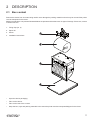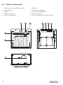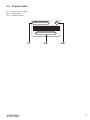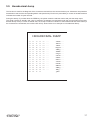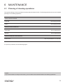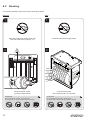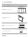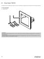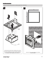
1
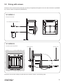
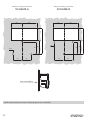
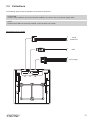
USER MANUAL
PLUS2
CUSTOM S.p.A.
CUSTOM S.p.A.
Via Berettine 2/B
43010 Fontevivo (PARMA) - Italy
Tel. : +39 0521-680111
Fax : +39 0521-610701
http: www.custom.biz
Customer Service Department:
Email : [email protected]
© 2014 CUSTOM S.p.A. – Italy.
All rights reserved. Total or partial reproduction of this manual in whatever form,
whether by printed or electronic means,
is forbidden. While guaranteeing that the
information contained in it has been carefully checked, CUSTOM S.p.A. and other
entities utilized in the realization of this
manual bear no responsibility for how the
manual is used.
Information regarding any errors found in it
or suggestions on how it could be improved
are appreciated. Since products are subject to continuous check and improvement,
CUSTOM S.p.A. reserves the right to make
changes in information contained in this
manual without prior notii cation.
The pre-installed multimedia contents
are protected from Copyright CUSTOM
S.p.A. Other company and product names
mentioned herein may be trademarks of
their respective companies. Mention of
third-party products is for informational
purposes only and constitutes neither
an endorsement nor a recommendation.
CUSTOM S.p.A. assumes no responsibility
with regard to the performance or use of
these products.
THE IMAGES USED IN THIS MANUAL ARE USED AS AN ILLUSTRATIVE EXAMPLES. THEY COULDN’T
GENERAL SAFETY INFORMATION
Your attention is drawn to the following
actions that could compromise the characteristics of the product:
• Read and retain the instructions which
follow.
• Follow all indications and instructions
given on the device.
• Make sure that the surface on which
the device rests is stable. If it is not, the
device could fall, seriously damaging it.
• Make sure that the device rests on a hard
(non-padded) surface and that there is
sufi cient ventilation.
• When positioning the device, make sure
cables do not get damaged.
• Use the type of electrical power supply
indicated on the device label. If uncertain, contact your dealer.
• Make sure the electrical system that
supplies power to the device is equipped
with a ground wire and is protected by a
differential switch.
• Do not block the ventilation openings.
• Do not insert objects inside the device as
this could cause short-circuiting or damage components that could jeopardize
printer functioning.
• Do not carry out repairs on the device
yourself, except for the normal maintenance operations given in the user
manual.
• Make sure that there is an easily-accessible outlet with a capacity of no less
than 10A closely to where the device is
to be installed.
• Periodically perform scheduled maintenance on the device to avoid dirt build-up
that could compromise the correct, safe
operation of the unit.
• Before any type of work is done on the
machine, disconnect the power supply.
• Do not touch the head heating line with
bare hands or metal objects. Do not
perform any operation inside the printer
immediately after printing because the
head and motor tend to become very
hot.
REPRODUCE THE DESCRIBED
MODEL FAITHFULLY.
UNLESS OTHERWISE SPECIFIED,
THE INFORMATION GIVEN IN THIS
MANUAL
ARE REFERRED TO ALL MODELS
IN PRODUCTION AT THE ISSUE
DATE OF THIS DOCUMENT.
GENERAL INSTRUCTIONS
CUSTOM S.p.A. declines all responsibility for accidents or damage to persons or
property occurring as a result of tampering,
structural or functional modii cations, unsuitable or incorrect installations, environments not in keeping with the equipment’s
protection degree or with the required temperature and humidity conditions, failure
to carry out maintenance and periodical
inspections and poor repair work.
THE CE MARK AFFIXED TO
THE PRODUCT CERTIFY
THAT THE PRODUCT SATISFIES THE BASIC SAFETY
REQUIREMENTS.
The device is in conformity with the essential Electromagnetic Compatibility and
Electric Safety requirements laid down in
Directives 2006/95/CE and 2004/108/CE
inasmuch as it was designed in conformity
with the provisions laid down in the following Standards:
• EN 55022 Class B (Limits and methods
of measurements of radio disturbance
characteristics of Information Technology Equipment)
• EN 55024 (Information Technology
Equipment – Immunity characteristics –
Limits and methods of measurement)
• EN 60950-1 (Safety of information
equipment including electrical business
equipment)
GUIDELINES FOR
THE DISPOSAL OF
THE PRODUCT
The crossed-out rubbish bin logo means
that used electrical and electronic products
shall NOT be mixed with unsorted municipal waste. For more detailed information
about recycling of this product, refer to the
instructions of your country for the disposal
of these products.
• Do not dispose of this equipment as
miscellaneous solid municipal waste, but
arrange to have it collected separately.
• The re-use or correct recycling of the
electronic and electrical equipment
(EEE) is important in order to protect
the environment and the wellbeing of
humans.
• In accordance with European Directive
WEEE 2002/96/EC, special collection
points are available to which to deliver
waste electrical and electronic equipment and the equipment can also be
handed over to a distributor at the moment of purchasing a new equivalent
type.
• The public administration and producers
of electrical and electronic equipment
are involved in facilitating the processes
of the re-use and recovery of waste electrical and electronic equipment through
the organisation of collection activities
and the use of appropriate planning arrangements.
• Unauthorised disposal of waste electrical
and electronic equipment is punishable
by law with the appropriate penalties.
The format used for this manual improves use of natural resources reducing the quantity of necessary paper to print this
copy.
MANUAL
For details on the commands,
refer to the manual with code 77200000002100
TABLE OF CONTENTS
1
INTRODUCTION . . . . . . . . . . . . . . . . . . . . . . . . . . . . . . . . . . . . . . . . . . . . . . . . . . . . . . . . . . . . . . 9
1.1 Document structure . . . . . . . . . . . . . . . . . . . . . . . . . . . . . . . . . . . . . . . . . . . . . . . . . . . . . . . . . . . . . . . . . 9
1.2 Explanatory notes used in this manual . . . . . . . . . . . . . . . . . . . . . . . . . . . . . . . . . . . . . . . . . . . . . . . . . . . 9
2
DESCRIPTION
2.1
2.2
2.3
2.4
2.5
2.6 Box content . . . . . . . . . . . . . . . . . . . . . . . . . . . . . . . . . . . . . . . . . . . . . . . . . . . . . . . . . . . . . . . . . . . . . . . 11
Device components . . . . . . . . . . . . . . . . . . . . . . . . . . . . . . . . . . . . . . . . . . . . . . . . . . . . . . . . . . . . . . . . 12
Product label . . . . . . . . . . . . . . . . . . . . . . . . . . . . . . . . . . . . . . . . . . . . . . . . . . . . . . . . . . . . . . . . . . . . . . 13
Key functions: power up . . . . . . . . . . . . . . . . . . . . . . . . . . . . . . . . . . . . . . . . . . . . . . . . . . . . . . . . . . . . . 14
Key functions: standby . . . . . . . . . . . . . . . . . . . . . . . . . . . . . . . . . . . . . . . . . . . . . . . . . . . . . . . . . . . . . . 15
Status led lashes . . . . . . . . . . . . . . . . . . . . . . . . . . . . . . . . . . . . . . . . . . . . . . . . . . . . . . . . . . . . . . . . . . 16
3
INSTALLATION . . . . . . . . . . . . . . . . . . . . . . . . . . . . . . . . . . . . . . . . . . . . . . . . . . . . . . . . . . . . . . . 17
3.1 3.2
3.3
3.4
3.5
3.6
“EASYLOCK” ixing system . . . . . . . . . . . . . . . . . . . . . . . . . . . . . . . . . . . . . . . . . . . . . . . . . . . . . . . . . . 17
Fixing with screws . . . . . . . . . . . . . . . . . . . . . . . . . . . . . . . . . . . . . . . . . . . . . . . . . . . . . . . . . . . . . . . . . . 19
Collections . . . . . . . . . . . . . . . . . . . . . . . . . . . . . . . . . . . . . . . . . . . . . . . . . . . . . . . . . . . . . . . . . . . . . . . 21
Pinout . . . . . . . . . . . . . . . . . . . . . . . . . . . . . . . . . . . . . . . . . . . . . . . . . . . . . . . . . . . . . . . . . . . . . . . . . . . 23
Serial port setting . . . . . . . . . . . . . . . . . . . . . . . . . . . . . . . . . . . . . . . . . . . . . . . . . . . . . . . . . . . . . . . . . . 25
Driver and SDK . . . . . . . . . . . . . . . . . . . . . . . . . . . . . . . . . . . . . . . . . . . . . . . . . . . . . . . . . . . . . . . . . . . . 27
4
OPERATION . . . . . . . . . . . . . . . . . . . . . . . . . . . . . . . . . . . . . . . . . . . . . . . . . . . . . . . . . . . . . . . . . . 29
. . . . . . . . . . . . . . . . . . . . . . . . . . . . . . . . . . . . . . . . . . . . . . . . . . . . . . . . . . . . . . . 11
4.1 Loading the paper roll . . . . . . . . . . . . . . . . . . . . . . . . . . . . . . . . . . . . . . . . . . . . . . . . . . . . . . . . . . . . . . . 29
5
CONFIGURATION. . . . . . . . . . . . . . . . . . . . . . . . . . . . . . . . . . . . . . . . . . . . . . . . . . . . . . . . . . . . 31
5.1 5.2
5.3
5.4
5.5
Coniguration mode . . . . . . . . . . . . . . . . . . . . . . . . . . . . . . . . . . . . . . . . . . . . . . . . . . . . . . . . . . . . . . . . 31
Setup report . . . . . . . . . . . . . . . . . . . . . . . . . . . . . . . . . . . . . . . . . . . . . . . . . . . . . . . . . . . . . . . . . . . . . . 32
Printer status . . . . . . . . . . . . . . . . . . . . . . . . . . . . . . . . . . . . . . . . . . . . . . . . . . . . . . . . . . . . . . . . . . . . . . 33
Printer parameters . . . . . . . . . . . . . . . . . . . . . . . . . . . . . . . . . . . . . . . . . . . . . . . . . . . . . . . . . . . . . . . . . 34
Hexadecimal dump . . . . . . . . . . . . . . . . . . . . . . . . . . . . . . . . . . . . . . . . . . . . . . . . . . . . . . . . . . . . . . . . . 37
6
MAINTENANCE . . . . . . . . . . . . . . . . . . . . . . . . . . . . . . . . . . . . . . . . . . . . . . . . . . . . . . . . . . . . . . 39
6.1 Planning of cleaning operations . . . . . . . . . . . . . . . . . . . . . . . . . . . . . . . . . . . . . . . . . . . . . . . . . . . . . . . 39
6.2 Cleaning . . . . . . . . . . . . . . . . . . . . . . . . . . . . . . . . . . . . . . . . . . . . . . . . . . . . . . . . . . . . . . . . . . . . . . . . . 40
6.3 Upgrade irmware . . . . . . . . . . . . . . . . . . . . . . . . . . . . . . . . . . . . . . . . . . . . . . . . . . . . . . . . . . . . . . . . . . 43
7
7
SPECIFICATION
7.1 7.2 7.3
7.4
7.5 7.6 Hardware speciications . . . . . . . . . . . . . . . . . . . . . . . . . . . . . . . . . . . . . . . . . . . . . . . . . . . . . . . . . . . . . 45
Character speciications in ESC/POS™ and PLUS emulation . . . . . . . . . . . . . . . . . . . . . . . . . . . . . . . . 48
Printer dimensions . . . . . . . . . . . . . . . . . . . . . . . . . . . . . . . . . . . . . . . . . . . . . . . . . . . . . . . . . . . . . . . . . 49
Power supply dimensions cod. 964GE010000003 . . . . . . . . . . . . . . . . . . . . . . . . . . . . . . . . . . . . . . . . . 50
Paper speciication . . . . . . . . . . . . . . . . . . . . . . . . . . . . . . . . . . . . . . . . . . . . . . . . . . . . . . . . . . . . . . . . . 51
Character sets in ESC/POS™ and PLUS emulation . . . . . . . . . . . . . . . . . . . . . . . . . . . . . . . . . . . . . . . 52
8
CONSUMABLES . . . . . . . . . . . . . . . . . . . . . . . . . . . . . . . . . . . . . . . . . . . . . . . . . . . . . . . . . . . . . 55
9 ACCESSORIES
. . . . . . . . . . . . . . . . . . . . . . . . . . . . . . . . . . . . . . . . . . . . . . . . . . . . . . . . . . . . . 45
. . . . . . . . . . . . . . . . . . . . . . . . . . . . . . . . . . . . . . . . . . . . . . . . . . . . . . . . . . . . . . 57
9.1 Grey frame 112X112 . . . . . . . . . . . . . . . . . . . . . . . . . . . . . . . . . . . . . . . . . . . . . . . . . . . . . . . . . . . . . . . . 58
10 TECHNICAL SERVICE . . . . . . . . . . . . . . . . . . . . . . . . . . . . . . . . . . . . . . . . . . . . . . . . . . . . . 63
8
1
INTRODUCTION
1.1
Document structure
This document includes the following chapters:
1
INTRODUCTION
information about this document
2
DESCRIPTION
general description of device
3
INSTALLATION
information required for a correct installation of the device
4
OPERATION
information required to make the device operative
5 CONFIGURATION description of the coniguration parameters of the device
6
information for a correct periodic maintenance
MAINTENANCE
7 SPECIFICATION technical speciication for the device and its accessories
8
CONSUMABLES
description and installation of the available consumables for the device
9
ACCESSORIES
description and installation of the available accessories for the device
11 TECHNICAL SERVICE
1.2
information required for contacting the technical service
Explanatory notes used in this manual
NOTE:
Gives important information or suggestions relative to the use of the device
ATTENTION:
Gives information that must be carefully followed to guard against damaging
the device
DANGER:
Gives information that must be carefully followed to guard against operator
injury or damage
9
10
2
DESCRIPTION
2.1
Box content
Remove the device from its carton being careful not to damage the packing material so that it may be re-used if the printer
is to be transported in the future.
Make sure that all the components illustrated below are present and that there are no signs of damage. If there are, contact
Customer Service.
1. Fixing clips (no. 2)
2. Paper roll
3. Printer
1
4. Installation instructions
2
3
4
• Open the device packaging.
• Take out the device.
• Take out the rest of the content.
• Keep the box, trays and packing materials in the event the printer must be transported/shipped in the future.
11
2.2
Device components
1. Socket for 8-42 Vdc extended range module
6. FEED key
2. Power supply port
7. OPEN key and status led
3. USB port
8. Paper out with serrated blade
4. RS232/TTL serial port
9. Paper compartment
5. Sensor for paper detection
10. Switch for RS232/TTL serial communication
7
6
8
9
TTL
12
RS232
10
5
4
3
2
1
2.3
Product label
PC = Product code (14 digits)
SN = Serial number
HW = Hardware release
XXXXXXXXXXXXXX
Rx
0000000000000000000
PC
SN
HW
13
2.4
Key functions: power up
POWER UP
Hold down
printing
SETUP report
Hold down
Fast
push
enter the SETUP MODE
Hold down
next
parameter
14
enter the FONT TEST MODE
Fast
push
modify
selected parameter
Hold down
printing
FONT TEST
Fast
push
skip the
FONT TEST
2.5
Key functions: standby
STANDBY
Fast push
advance the paper
(preset length)
15
2.6
Status led lashes
The status of the device is sent to the serial port. To get a visual feedback of the signallings is necessary to build a cable
to be connected to the serial port (see par. 3.3).
The Status led indicates hardware status of device. Given in the table below are the various led signals and the corresponding device status.
STATUS LED
16
DESCRIPTION
OFF
PRINTER OFF
ON
PRINTER ON: NO ERROR
x2
HEADING OVER TEMPERATURE
x3
PAPER END
x4
POWER SUPPLY VOLTAGE INCORRECT
x5
RECEPTION ERRORS
(PARITY, FRAME ERROR, OVERRUN ERROR)
x6
COMMAND NOT RECOGNIZED
x7
COMMAND RECEPTION TIME OUT
3
INSTALLATION
3.1
“EASYLOCK” ixing system
The device includes two plastic clips for ixing to the panel. This system allows you to lock the machine on the panels of thickness max. 8mm and requires no tools. Proceed as follows:
NOTE: All the dimensions shown in following igures are in millimetres.
1
2
82
82
Insert the fixing clips into the seat
on both the device sides
3
MAX. 8
Insert the device inside the panel
Push the two fixing clips
to strike the panel
17
4
To remove the fixing clips
lift the lever shown in figure
with a small screwdriver
18
3.2
Fixing with screws
The device can be secured to the panel with 3 screws (not supplied) to be tighten on the rear side of the device (SCHEME
A) or from the paper compartment (SCHEME B).
SCHEME A
Fixing on the rear side
No.3 self-tapping screws for plastic d = 3
max
6+A
A
SCHEME B
Fixing from paper compartment
No.3 threaded nut
No.3 M3 screws
The panel must provide a drilling complies with the measures shown in the following page.
19
Drilling for mounting on panel with
Drilling for mounting on panel with
SCHEME A
SCHEME B
30
40
75
40
75
30
25
25
View of the drilling
NOTE: All the dimensions shown in following igures are in millimetres.
20
25
25
40
35
ø3.5
40
35
ø3.5
3.3
Collections
The following igure shows the possible connections for the device.
ATTENTION:
In some using conditions, we recommend the installation of a ferrite core on the power supply cable.
NOTE:
If RS232 and USB connectors are inserted, communication port is USB.
Standard model 4÷7.5 Vdc
Serial
RS232/TTL
USB
Power supply
J3
J1
J8
21
Model with the 8÷42 Vdc extended range module plugged
Serial
RS232/TTL
USB
Power supply
22
3.4
Pinout
POWER SUPPLY
1
4
JST male connector (S4B-PH-K-S)
1 GND
2 GND
J8
3 +VP
4 +VCC
ATTENTION:
Respect power supply polarity.
NOTE: Power supply cable
The following igure shows the connector pinout of the power supply cable for the device:
Female JST connector
series PHR-4
Power supply cable
1
4
PIN
Segnal
1
Cable
color
Black
2
Black
GND
3
Orange
+VP
4
Red
+VCC
GND
MINI USB INTERFACE
5
1
Female MINI USB type B connector
1 VPLUG
2 D03 D0+
4 n.c.
J1
5 GND
SH1 GND
SH2 GND
SH3 GND
SH4 GND
23
RS232/TTL SERIAL INTERFACE
6
1
Molex male connector 53048-0610 series (90°)
1 RT
J3
2 TX
During transmission, oscillates between “0” and “1” depending on data
3 RX
During reception, oscillates between “0” and “1” depending on data
4 GND
5 EXT-FEED
6 EXT-LED
NOTES:
Given the presence of the RS232 standard, logic value “0” corresponds to a voltage level of between +3Vdc and +15Vdc
and logic value “1” corresponds to a voltage level of between -3Vdc and -15Vdc.
1
2
3
4
5
6
DTR
DTR
TX
RX
RX
TX
GND
GND
FEED
LED
1
2
DEVICE
1
2
3
4
5
6
7
8
9
DB9
MOLEX 51021
6 pin female
Device > PC connection
The following pictures shows an example of connections between the printer and a personal computer using a 9 pin
RS232 serial connectors:
PC
When use a serial cable, we recommend the installation of a ferrite core on the power supply cable.
24
3.5
Serial port setting
To set the serial port of the device, slide the switch shown in igure in the correct position:
RS232
RS232
TTL
TTL
In the serial protocol, the signals which distinguish the communication are TD, RD, and RTS if the RTS/CTS protocol has
been selected while, if the XON/XOFF protocol has been selected, the signals are TD and RD.
Transmission format
START
BIT
BIT 0
BIT 1
BIT 2
BIT 3
BIT 4
BIT 5
BIT 7(1)
BIT 6
PARITY
BIT(2)
STOP
BIT
NEXT
START
BIT
Notes:
(1) Bit 7 is present if only in the printer set-up is enabled 8 bit/char as data length.
(2) Parity Bit is preset if only in the printer set-up the parity is enabled.
RTS/CTS Protocol
STOP
RD
DATA
DATA
START
STOP
START
STOP
DATA
WAIT
START
RTS
25
XON/XOFF protocol
STOP
RD
STOP
DATA
WAIT
DATA
START BIT
START BIT
STOP
TD
0x13XOFF
START BIT
26
STOP
0x11XON
START BIT
3.6
Driver and SDK
The drivers are available for the following operating system:
OPERATING
SYSTEM
DESCRIPTION
INSTALLATION PROCEDURE
Driver per Windows XP
Driver per Windows VISTA (32/64bit)
Windows
Driver per Windows 7 (32/64bit)
From the START menu, press Run
and type-in the path where the SW
was saved on your PC, then click OK.
Follow the instructions that appear
on the screen to install the driver.
Driver per Windows 8 (32/64bit)
Follow the instruction get back on the
README.TXT ile. You can ind it in the
software package downloaded in advance.
Linux
Android
Library for CustomAndroidAPI
Extract the zipped folder to
the destination path desired.
Follow the instructions present
in the software package that you
downloaded on how to install
and use the library.
NOTA:
All drivers can be found in the DOWNLOAD section of the web site www.custom.biz.
27
28
4
OPERATION
4.1
Loading the paper roll
To change the paper proceed as follows. At every change of paper, check inside the printer to locate and remove any
scraps of paper.
1
3
Open the printer cover
2
Close the printer cover
4
Place the roll in the paper compartment and
pull out the paper for a few centimetres
Remove the excess paper
29
5
Print density
Thermal paper
√ -50%
√ -37%
√ -25%
√ -12%
√ 0
√ +12%
√ +25%
√ +37%
√ +50%
Print density
√ Linerless
Linerless thermal paper
When using normal thermal paper, set
the parameter "Print density" on one of the values
between -50% and +50% (see chap. 5).
When using linerless thermal paper, set the
parameter "Print density" on "linerless" (see chap. 5).
30
5
CONFIGURATION
5.1
Coniguration mode
To enter the coniguration mode and print a SETUP report with the operating parameters of the printer, proceed as follows.
1
2
Autofeed ....................................: CR enabled
Chars/Inch .................................: A=13B=17cpi
Columns 22 cpi..........................: 40 columns
Code Table [num] ......................: 00
Font Type...................................: International
Speed/quality.............................: Normal
PaperEnd Buffer Clear ..............: Disabled
Print density...............................: 0%
The printer prints the report with
parameters for printer settings
3
Enter
printer
setup
While pressing the FEED key, switch on the
printer by inserting the power supply cable
Press the FEED key to enter
the configuration mode
31
5.2
Setup report
The following igure show the setup report of the printer. The shown values for parameters are sample values; for the list and the description of printer parameters see the following paragraphs.
KEYS FUNCTIONS
PRINTER NAME and
FIRMWARE MODULES
RELEASE
[ FAST PUSH] to skip Setup
[ PUSH ] to enter Printer setup
PLUS2 printer
SCODE <code>
FCODE <code>
-
rel 1.00
rel 1.00
PRINTER SETTINGS
DEVICE
STATUS
PRINTER
PARAMETERS
32
PRINTER TYPE ....................................PLUS2
PRINTING HEAD TYPE ........................E48-CE
INTERFACE ..........................................RS232
PROGRAM MEMORY TEST.................OK
DYNAMIC RAM TEST...........................OK
EEPROM TEST.....................................OK
HEAD VOLTAGE
[V] = 04.84
HEAD TEMPERATURE
[°C] = 25
POWER ON COUNTER
= 4
PAPER PRINTED
[cm] = 40
Printer Emulation ............................. :
RS232 Baud Rate ........................... :
RS232 Data Length ......................... :
RS232 Parity ................................... :
RS232 Handshaking ....................... :
Busy Condition ................................ :
USB Address Number ..................... :
Print Mode ....................................... :
Autofeed .......................................... :
Chars / inch ..................................... :
Columns 22 cpi................................ :
Code Table [num] ............................ :
Font Type......................................... :
Speed / Quality................................ :
PaperEnd Buffer Clear .................... :
Print Density.................................... :
PLUS
9600 bps
8 bits/chr
None
Xon/Xoff
RxFull
0
Normal
CR Enabled
A=13 B=17 cpi
40 columns
00
International
Normal
Disabled
0%
5.3
Printer status
The printer operating status is indicated in the coniguration print-out in which, next to the name of the components displayed, the following information is given:
PRINTER TYPE
device model
PRINTING HEAD TYPE
print head model
INTERFACE
interface present
PROGRAM MEMORY TEST
OK appears if functioning and NOT OK if faulty
DYNAMIC RAM TEST
OK appears if functioning and NOT OK if faulty
EEPROM TEST
OK appears if functioning and NOT OK if faulty
HEAD VOLTAGE
voltage of the head
HEAD TEMPERATURE
temperature of the head
POWER ON COUNTER
number of power-ups made
PAPER PRINTED
centimetres of paper printed
33
5.4
Printer parameters
This printer allows the coniguration of the parameters listed in the following table.
The parameters marked with the symbol D are the default values.
Settings remain active even after the printer has been turned off and they are stored in non-volatile memory.
PRINTER EMULATION
Available emulations for the device:
PLUS D
ESC/POSTM
RS232 BAUD RATE
Communication speed of the serial interface:
115200
57600
38400
19200
9600 D
4800
2400
1200
NOTE: Parameter valid only with serial interface.
RS232 DATA LENGTH
Number of bit used for characters encoding:
7 bits/car
8 bits/car D
NOTE: Parameter valid only with serial interface.
RS232 PARITY
Bit for the parity control of the serial interface:
None D = parity bit omitted
Even = even value for parity bit
Odd =
odd value for parity bit
NOTE: Parameter valid only with serial interface.
RS232 HANDSHAKING
Handshaking:
XON/XOFF D = software low control
Hardware =
hardware low control (CTS/RTS)
NOTES:
Parameter valid only with serial interface.
When the receive buffer is full, if handshaking is set to XON/XOFF, the printer sends the XOFF (0x13) on the
serial port. When the receive buffer has cleared once again, if handshaking is set to XON/XOFF, the printer
sends the XON (0x11) on the serial port.
BUSY CONDITION
Activation mode for Busy signal:
OffLine/ RXFull = Busy signal is activated when the printer is both in OffLine status and
the buffer is full
RXFull D =
Busy signal is activated when the buffer is full
NOTE: Parameter valid only with serial interface.
34
USB ADDRESS NUMBER
Numerical address code for the univocal identiication of the USB device (in case of more
than a USB device connected with the same PC):
0D
1
2
PRINT MODE
3
4
5
6
7
8
9
Printing mode:
Normal D = enables printing in normal writing way
Reverse = enables printing rotated 180 degrees
AUTOFEED
Setting of the Carriage Return character:
CR disabled = Carriage Return disabled
CR enabled D = Carriage Return enabled
CHARS / INCH
Font selection:
A = 13 cpi, B = 17 cpi D
A = 17 cpi, B = 22 cpi
NOTES:
CPI = Characters Per Inch
COLUMNS 22 CPI
Number of columns to use when the 17x22 cpi font is in use (see parameter CHARS /
INCH):
40 columns D
42 columns
NOTES:
The parameter is printed only with PLUS emulation enabled.
To modify the parameter, set the PLUS emulation (see parameter PRINTER EMULATION) and the 17x22cpi
font (see parameter CHARS / INCH):
CODE TABLE [num]
Identiier number of the character code table to use.
The numeric value of the identiier is made up with the following two parameters for the
setting of two digits for the tens and the units:
Setting the digit for tens:
CODE TABLE [num x 10]
0D
1
2
3
4
5
Setting the digit for units:
CODE TABLE [num x 1]
0D
1
2
3
4
5
6
7
8
9
NOTES:
See the paragraph 7.6 to learn about the character tables corresponding to the identiication numbers set with this parameter.
The character tables set with this parameter are the same set with the command 0x1B 0x74 (refer to the
Commands Manual of the device).
35
FONT TYPE
Setting of the font type:
International D
Chinese GB18030
Korean PC949
=
=
=
Enables the use of the 256-characters font tables
Enables the use of the chinese extended font GB18030-2000
Enables the use of the korean font PC949
NOTE: When the “INTERNATIONAL” font type is enabled, must be selected the desired character code
table (parameter “CODE TABLE”). When the chinese or korean font is enabled, the selection of the character
code table is suspended (par. “CODE TABLE”).
SPEED / QUALITY
Setting of printing speed and printing quality:
Normal D
High Quality
PAPEREND BUFFER
CLEAR
PRINT DENSITY
Cleaning mode of the data in receive buffer, if the printing is stopped due to lack of paper:
Disabled D = The data remain in the receive buffer. When the paper runs out, the printer
keeps the remaining data in the receive buffer and prints the remaining
portion of the ticket after that the new paper is loaded.
Enabled = When the paper runs out, all data in the receive buffer are deleted.
Adjusting the printing density:
-50%
-37%
-25%
36
-12%
0D
+12%
+25%
+37%
+50%
Linerless
5.5
Hexadecimal dump
This function is used for the diagnosis of the characters received from the communications port. Characters are printed as
hexadecimal code and the corresponding ASCII code (see below). Each line is preceded by a counter in hexadecimal that
indicates the number of bytes received.
During the startup, if you hold down the FEED key, the printer enters the self-test routine and print the setup report.
The printer remains in standby until a key is pressed or characters are received through the communication port (Hexadecimal Dump mode). For each character sent, the receipt contain an indication of the hexadecimal and ASCII values (if
the characters are underlined, the receive buffer is full). Shown below is an example of a Hexadecimal Dump:
HEXADECIMAL DUMP
31
39
37
68
73
66
65
6F
6F
77
72
6B
64
73
66
6A
32
30
38
6B
64
73
69
72
75
65
69
6C
66
64
6B
6B
33
31
39
6A
66
64
6F
69
77
72
6F
73
6B
66
F2
6C
34
32
75
73
6B
66
79
75
65
69
75
64
73
6B
6A
68
35
33
69
64
6A
6B
75
77
72
6F
77
66
64
6A
73
...
...
...
...
...
...
...
...
...
...
...
...
...
...
...
12345 ...
90123 ...
789ui ...
hkjsd ...
sdfkj ...
fsdfk ...
eioyu ...
oriuw ...
ouwer ...
werio ...
riouw ...
klsdf ...
dfksd ...
sdfkj ...
fk≥j ...
jklh
37
38
6
MAINTENANCE
6.1
Planning of cleaning operations
The regular cleaning of the device keeps the print quality and extends its life. The following table shows the recommended
planning for the cleaning operations.
EVERY PAPER CHANGE
Printhead
Use isopropyl alcohol
Rollers
Use isopropyl alcohol
EVERY 5 PAPER CHANGES
Paper path
Use compressed air
Sensors
Use compressed air
EVERY 6 MONTHS OR AS NEEDED
Printer case
Use compressed air or a soft cloth
For speciic procedures, see the following pages.
NOTE:
If you use the device in dusty environments, you must reduce the intervals between the cleaning operations.
39
6.2
Cleaning
For periodic cleaning of the printer, see the instructions below
Sensors
Case
1
1
Disconnect the power supply cable and
open the printer cover (see par. 4.1)
2
2
To clean the machine,
use compressed air or a soft cloth.
Clean the printer sensor
by using compressed air
ATTENTION:
Do not use alcohol, solvents, or hard brushes.
Do not let water or other liquids get inside the machine.
ATTENTION:
Do not use alcohol, solvents, or hard brushes.
Do not let water or other liquids get inside the machine.
Alcohol, solvent
40
Disconnect the power supply cable
ON
Alcohol, solvent
ON
Paper path
Print head
1
1
Disconnect the power supply cable and
open the printer cover (see par. 4.1)
2
Disconnect the power supply cable and
open the printer cover (see par. 4.1)
2
Clean the area involved in the passage of paper
by using compressed air.
Clean the printing head by using
a non-abrasive cloth moistened with isopropyl.
ATTENTION:
Do not use solvents, or hard brushes.
Do not let water or other liquids get inside the machine.
ATTENTION:
Do not use alcohol, solvents, or hard brushes.
Do not let water or other liquids get inside the machine.
Alcohol, solvent
ISOPROPYL ALCOHOL
ON
ON
41
Printing roller
1
Disconnect the power supply cable and
open the printer cover (see par. 4.1)
2
ISOPROPYL ALCOHOL
Clean the printing roll by using
a non-abrasive cloth moistened with isopropyl.
ATTENTION:
Do not use solvents, or hard brushes.
Do not let water or other liquids get inside the machine.
ON
42
6.3
Upgrade irmware
9. Select the serial communication port (ex. COM1):
WARNING: During communication between PC/printer
for the irmware update it is strictly forbidden to disconnect the communication cable or to remove the power
supply of the devices not to endanger the proper functioning of the printer.
NOTES:
The latest irmware of the printer is available in the download area of the web site www.custom.biz
C:\PLUS2.PSW
Install on the PC used for printer upgrading the UPGCEPRN software available in the download area of the
web site www.custom.biz.
UPDATE VIA SERIAL INTERFACE
Proceed as follows:
1. Write down the product code (14 digits) printed on the
product label (see par. 2.3).
2. Go to the web site www.custom.biz and download the
appropriate irmware release from the DOWNLOAD area.
3. Print the SETUP report (see chapter 5).
4. Switch OFF the printer.
5. Connect the printer to the PC using a serial cable (see
paragraph 3.3).
6. Switch ON the printer.
7. Launch the software UPGCEPRN.
8. Select the update ile .PSW location:
10. Detecting and setting of the parameters necessary for
serial communication are performed automatically and
then updating begins.
11. After a few minutes a message on the screen warns
that the update is completed.
12. Print a new SETUP report to verify the new irmware release (see chapter 5).
43
UPDATE VIA USB INTERFACE
Custom PLUS2
ATTENTION:
Only during the irmware update, the connection between PC and printer must be direct, without the use
of HUB devices.
Only during the irmware update, do not connect or disconnect other USB devices.
C:\PLUS2.PSW
NOTE: For communication via USB you must install on
PC the printer driver available in the download area of
the web site www.custom.biz.
Proceed as follows:
1. Write down the product code (14 digits) printed on the
product label (see par. 2.3).
C:\PLUS2.PSW
2. Go to the web site www.custom.biz and download the
appropriate irmware release from the DOWNLOAD area.
3. Print the SETUP report (see chapter 5).
4. Switch OFF the printer.
5. Connect the printer to the PC using a USB cable (see
paragraph 3.3).
6. Switch ON the printer.
7. Launch the software UPGCEPRN.
8. Select the update ile .PSW location:
10. After a few minutes a message on the screen warns
that the update is completed.
11. Print a new SETUP report to verify the new irmware release (see chapter 5).
9. Select item USB and then select the USB device among
those proposed (ex. PLUS2):
44
7
SPECIFICATION
7.1
Hardware speciications
GENERAL
Sensors
Emulations
Printing driver
Head temperature, paper presence
PLUS
ESC/POSTM
Windows XP, VISTA (32/64bit), Windows 7 (32/64bit), Windows 8 (32/64bit)
Linux,
Android
INTERFACES
USB port
RS232/TTL serial port
12 Mbit/sec (USB 2.0 full speed)
from 1200 to 115200 bps
MEMORIES
Receive buffer
16 Kbytes
Flash memory
4 Mbytes (+768Kbytes internal)
RAM memory
128 Kbytes
Graphic memory
Logos dynamic management (max 32 Kbytes graphic memory)
PRINTER
Resolution
Printing method
203 dpi (8 dot/mm)
Thermal, ixed head
Printing width
48 mm
Printing mode
Normal, 90°, 180°, 270°
Printing format
Character fonts
Height/Width from 1 to 8, bold, reverse, underlined, italic
54 character code tables (see par. 7.6)
Extended chinese GB18030-2000
Korean PC949
45
Printable barcode
Printing speed (1) (2)
UPCA, UPCE, EAN13, EAN8,
CODE39, ITF, CODABAR,
CODE93, CODE128, CODE32,
PDF417, QRCODE
max. 50 mm/sec
PAPER
Type of paper
Paper width
Paper weight
Paper thickness
Recommended types of paper
External roll diameter
External roll core diameter
Thermal rolls, heat-sensitive side on outside of roll
Linerless thermal rolls (see paragraph 7.5)
57 mm ± 0,5 mm
from 55 g/m2 to 70 g/m2
from 63 μm to 85 μm
KANZAN KF50 and KP460
MITSUBISHI PG5075
max. 50 mm
12 mm (+ 1mm)
Paper end
Not attached to roll core
Core type
Cardboard or plastic
PRINTER ELECTRICAL SPECIFICATIONS
Power supply
standard model
From 4 to 7.5 Vdc ±10% (optional external power supply)
model with the extended range
module plugged
From 8 to 42 Vdc ±10% (optional external power supply)
Medium consumption (2)
standard model
1.25 A (4Vdc)
0.7 A (7.5Vdc)
model with the extended range
module plugged
0.21 A (8Vdc)
1 A (42Vdc)
Stand-by consumption
standard model
46
0.060 A
model with the extended range
module plugged
0.060 A
ELECTRICAL SPECIFICATIONS POWER SUPPLY cod. 964GE010000003
Power supply voltage
Frequency
Current (output)
Power
from 90 Vac to 264 Vac
from 50 Hz to 60 Hz
5A
25W
ENVIRONMENTAL CONDITIONS
Operating temperature
Relative humidity
Storage temperature
Storage relative humidity
from 0°C to +50°C
from 10% Rh to 85% Rh
from -20 °C to +70 °C
from 10% Rh to 90% Rh
NOTES:
(1) : Respecting the regular schedule of cleaning for the device components.
(2) : Referred to a standard CUSTOM receipt (L=10cm, Density = 12,5% dots on).
47
7.2
Character speciications in ESC/POS™ and PLUS emulation
Character set
Character density
3
13 cpi
17 cpi
22 cpi
Number of columns
24
32
40/42
Chars / sec
360
480
640
Lines / sec
15
15
15
2x3
1,5 x 3
1,125 x 3
Characters (L x H mm)-Normal
48
7.3
Printer dimensions
Length
56.9 mm
Length with cover open
111 mm
Height
85 mm
Width
85 mm
Weight
141 g
NOTE:
Dimensions referred to devices without paper roll.
All the dimensions shown in following igures are in millimetres.
56.9
43.2
85
85
70
49
7.4
Power supply dimensions cod. 964GE010000003
Length
90.6 mm
Height
28,8 mm
Width
51 mm
NOTE: All the dimensions shown in following igures are in millimetres.
79
55
25.4
10.5
11.6
+V
41
51
-V
N
L
7.62
3
M
2-
PE
66.5
28.8
12
14
1.9
3
M
2-
50
7.5
Paper speciication
Linerless thermal paper
LINERLESS paper is a thermal paper with a self-adhesive layer without liner (on non-thermal side). For the better use with
the printer the self-adhesive area must comply with the following dimensions:
THERMAL SIDE
SELF-ADHESIVE
10
10
57 ± 0.5
LINERLESS PAPER SPECIFICATIONS
Self-adhesive
Water based acrylic
Self-adhesive mass
Permanent 16 gr/mq ±2gr
Total thickness
93 μm ±2 μm
Total weight
96 gr/mq ±2gr
Recommended temperature
Stick
from +15°C to +40°C
Storage
from +10°C to +40°C
Resistance after stick
from -10°C to +50°C
WARNING:
Do not set “Printer Density” parameter on “Linerless” mode during the printer SETUP (see user manual) with common
thermal paper.
In “Linerless” mode, if the printer is turned off a few hours, the irst row of the press could be compressed, during the turning on. It is recommended to perform one or more paper FEED before printing.
51
7.6
Character sets in ESC/POS™ and PLUS emulation
The printer has 3 internal fonts with a width of 13, 17, 22 cpi, which can be associated with one of the coding tables stored
on the device.
To know the coding tables actually stored on the device, print the font test (see par.2.4).
The selection of the font and the encoding table is done via command (see the commands manual of the device) or through
the Setup procedure by properly setting the parameter “Chars / Inch”, “Code Table” and “Font Type” (see par. 5.4).
The following is the complete list of coding tables that can be installed on the device.
<CodeTable>
52
Character Tables
0
PC437 - U.S.A., Standard Europe
1
Katakana
2
PC850 - Multilingual
3
PC860 - Portuguese
4
PC863 - Canadian/French
5
PC865 - Nordic
11
PC851 - Greek
on request
12
PC853 - Turkish
on request
13
PC857 - Turkish
on request
14
PC737 - Greek
on request
15
ISO8859-7 - Greek
on request
16
WPC1252
17
PC866 - Cyrillic 2
18
PC852 - Latin 2
19
PC858 for Euro symbol at position 213
20
KU42 - Thai
on request
21
TIS11 - Thai
on request
26
TIS18 - Thai
on request
30
TCVN_3 - Vientamese
on request
31
TCVN_3 - Vientamese
on request
32
PC720 - Arabic
on request
33
WPC775 - Baltic Rim
on request
on request
<CodeTable>
Character Tables
34
PC855 - Cyrillic
on request
35
PC861 - Icelandic
on request
36
PC862 - Hebrew
37
PC864 - Arabic
38
PC869 - Greek
on request
39
ISO8859-2 - Latin 2
on request
40
ISO8859-15 - Latin 9
on request
41
PC1098 - Farci
on request
42
PC1118 - Lithuanian
on request
43
PC1119 - Lithuanian
on request
44
PC1125 - Ukranian
on request
45
WPC1250 - Latin 2
46
WPC1251 - Cyrillic
47
WPC1253 - Greek
48
WPC1254 - Turkish
49
WPC1255 - Hebrew
50
WPC1256 - Arabic
51
WPC1257 - Baltic Rim
52
WPC1258 - Vientamese
53
KZ1048 - Kazakhstan
255
Space page
on request
53
54
8
CONSUMABLES
The following table shows the list of available consumables for device:
DESCRIPTION
CODE
67300000000344
THERMAL PAPER ROLL
Width = 57mm
Ø external = 50mm
Ø core = 12mm
Length = 30 mt
67300000000346
LINERLESS THERMAL PAPER ROLL
Width = 57mm
Ø external = 50mm
Ø core = 12mm
Length = 16 mt
55
56
9
ACCESSORIES
The following table shows the list of available accessories for device:
DESCRIPTION
CODE
964GE010000003
POWER SUPPLY
(for technical speciications, see the paragraph 7.1)
974CW010000315
GREY FRAME 112X112 (WITH CLIPS)
(see the paragraph 9.1)
44000000033000
CABLE KIT
POWER SUPPLY + SERIAL/TTL INTERFACE 5 VOLT
(500mm)
979CW180000001
8÷42 VDC EXTENDED RANGE MODULE
57
9.1
Grey frame 112X112
An adaptor frame is available and makes the device mechanically compatible with CUSTOM F and P series panel printers.
The kit is composed of:
1. Fixing clips (No.2)
2. Adaptor frame
1
2
WARNING:
Pay attention that the external frame, the cover and the printer frame are made from polypropylene, so it’s better to
keep away from:
Ammonia, Methanol, Acetone, Washing-up liquid, Benzol, Dishwasher liquid, Hydrocarbon, Dichloromethane, Perchloroethylene, Ethylene, Trichlorethylene, Toluene.
58
Assembly instructions
NOTE: All the dimensions shown in following igures are in millimetres.
1
2
113
113
Sled with
beveled
corner
Gears
cover
Fit the device into the frame, making sure to orient
the side of the gears cover at the sled for hooking of
the frame (with beveled corner). Secure the printer
by using the clips supplied with the device.
Insert the device assembled with the frame
inside the panel
59
3
5
Insert the fixing clips included in the assembly kit
into the seat on both the frame sides
4
MAX. 10
Push the two fixing clips
to strike the panel
60
To remove the fixing clips
lift the lever shown in figure
with a small screwdriver
Printer dimensions with the frame assembled
119
119
123.2
17.4
max 46.5
112x112
61
TTL
RS232
62
10
TECHNICAL SERVICE
In case of failure, contact the Technical Service by sending an e-mail to [email protected] detailing:
1. Product code
2. Serial number
3. Hardware release
4. Firmware release
To get the necessary data, proceed as follows:
1
3
XXXXXXXXXXXXXX
Rx
0000000000000000000
Write down the data printed
on the product label (see paragraph 2.3)
2
FW
[email protected]
Customer Service Department
Send an e-mail to the Technical Service,
with the data collected
[ FAST PUSH] to skip Setup
[ PUSH ] to enter Printer setup
PLUS2 printer
SCODE <code>
FCODE <code>
-
rel 1.00
rel 1.00
PRINTER SETTINGS
PRINTER TYPE ....................................PLUS2
PRINTING HEAD TYPE ........................E48-CE
INTERFACE ..........................................RS232
PROGRAM MEMORY TEST.................OK
DYNAMIC RAM TEST...........................OK
Print a Setup report (see paragraph 5.1)
The Setup report shows
the firmware release
63
Rev. 1.00
Part Number : 76200000004700
CUSTOM S.p.A.
World Headquarters
Via Berettine, 2/B - 43010 Fontevivo, Parma ITALY
Tel. +39 0521 680111 - Fax +39 0521 610701
[email protected] - www.custom.biz
All rights reserved
www.custom.biz