1
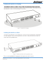
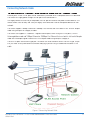
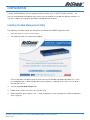
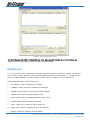
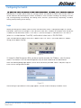
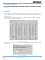
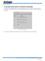
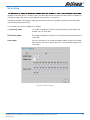
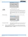
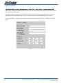
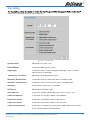
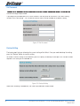
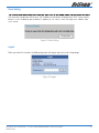
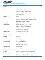
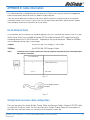
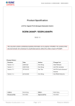
Contents
ABOUT THIS GUIDE ................................................................................................................................ 4
Purpose ............................................................................................................................. 4
Terms/Usage...................................................................................................................... 4
INTRODUCTION...................................................................................................................................... 5
Fast Ethernet Technology .................................................................................................... 5
Gigabit Ethernet Technology ................................................................................................ 5
Switching Technology ......................................................................................................... 6
VLAN (Virtual Local Area Network) ....................................................................................... 6
Power over Ethernet (PoE) ................................................................................................... 6
Features ............................................................................................................................ 7
UNPACKING AND INSTALLATION ............................................................................................................. 8
Unpacking ......................................................................................................................... 8
Installation ......................................................................................................................... 8
Installing the Switch on a Desktop ....................................................................................... 9
Installing the Switch on a Rack ............................................................................................ 9
Connecting Network Cable ................................................................................................ 11
IDENTIFYING EXTERNAL COMPONENTS ................................................................................................ 13
Front Panel ...................................................................................................................... 13
Rear Panel ....................................................................................................................... 14
UNDERSTANDING LED INDICATORS ...................................................................................................... 15
CONFIGURATION .................................................................................................................................. 17
Installing the Web Management Utility ............................................................................... 17
Discovery List .................................................................................................................. 18
Monitor List ..................................................................................................................... 19
View Trap ......................................................................................................................... 19
Web Access ..................................................................................................................... 22
Configuring the Switch...................................................................................................... 23
Setup Menu ..................................................................................................................... 24
Configuring Setup Setting ................................................................................................. 25
Port Settings .................................................................................................................... 25
VLAN Settings (Virtual Local Area Network) ........................................................................ 27
Trunk Setting ................................................................................................................... 28
PoE Setting ...................................................................................................................... 30
Device Status ................................................................................................................... 32
Statistic .......................................................................................................................... 33
System Setting ................................................................................................................ 34
2
NP2500 24-Port 10/100 PoE + 2-Port 10/100/1000 WebSMART Switch User Guide
YML842 Rev1
APPENDIX A Technical Specifications.................................................................................................... 38
APPENDIX B Cable Information ............................................................................................................. 41
RJ-45 Network Ports ....................................................................................................... 41
Straight and crossover cable configuration ........................................................................ 41
Straight-Through Cabling .................................................................................................. 42
Cross-Over Cabling .......................................................................................................... 42
APPENDIX C Registration and Warranty Information ............................................................................... 43
Contact Information .......................................................................................................... 43
Copyright Information ....................................................................................................... 43
Customer Information ....................................................................................................... 43
NP2500 24-Port 10/100 PoE + 2-Port 10/100/1000 WebSMART Switch User Guide
YML842 Rev1
3
ABOUT THIS GUIDE
Congratulations on your purchase of the NP2500 24-Port 10/100 PoE + 2-Port 10/100/1000 WebSMART
Switch. This Switch integrates 100Mbps Fast Ethernet and 10Mbps Ethernet network capabilities in a highly
flexible package. Since this Switch’s Port-1 to Port-24 are Power over Ethernet (PoE) ports, it will automatically detect the presence of IEEE 802.3af-compliant devices and will provide power through these PoE ports.
The Switch provides up to 15.4Watts per port and can be connected to WLAN access point, IP phone, video
camera, and other PD devices. The Switch will automatically detect the network appliance’s requirements,
and the Switch will supply the required power current to each appliance.
Purpose
This guide discusses how to install your NP2500 24-Port 10/100 PoE + 2-Port 10/100/1000 WebSMART
Switch.
Terms/Usage
In this guide, the term “Switch” (first letter upper case) refers to your NP2500 24-Port 10/100 PoE + 2-Port
10/100/1000 WebSMART Switch and “switch” (first letter lower case) refers to other Ethernet switches.
4
NP2500 24-Port 10/100 PoE + 2-Port 10/100/1000 WebSMART Switch User Guide
YML842 Rev1
INTRODUCTION
This chapter describes the features of the NP2500 24-Port 10/100 PoE + 2-Port 10/100/1000 WebSMART Switch and some background information about Fast Ethernet, Gigabit Ethernet, Switching, VLAN
and Power over Ethernet technologies.
Fast Ethernet Technology
The growing importance of LANs and the increasing complexity of desktop computing applications are
fueling the need for high performance networks. A number of high-speed LAN technologies have been
proposed to provide greater bandwidth and improve client/server response times. Among them, 100BASET (Fast Ethernet) provides a non-disruptive, smooth evolution from the current 10BASE-T technology. The
non-disruptive and smooth evolution nature, and the dominating potential market base, virtually guarantees
cost-effective and high performance Fast Ethernet solutions.
100Mbps Fast Ethernet is a standard specified by the IEEE 802.3 LAN committee. It is an extension of the
10Mbps Ethernet standard with the ability to transmit and receive data at 100Mbps, while maintaining the
CSMA/CD Ethernet protocol. Since the 100Mbps Fast Ethernet is compatible with all other 10Mbps Ethernet
environments, it provides a straightforward upgrade and takes advantage of the existing investment in hardware, software, and personnel training.
Gigabit Ethernet Technology
Gigabit Ethernet is an extension of IEEE 802.3 Ethernet utilizing the same packet structure, format, and support for CSMA/CD protocol, full duplex, flow control, and management objects, but with a tenfold increase in
theoretical throughput over 100Mbps Fast Ethernet and a one hundred-fold increase over 10Mbps Ethernet.
Since it is compatible with all 10Mbps and 100Mbps Ethernet environments, Gigabit Ethernet provides a
straightforward upgrade without wasting a company’s existing investment in hardware, software, and trained
personnel. The increased speed and extra bandwidth offered by Gigabit Ethernet are essential to coping
with the network bottlenecks that frequently develop as computers and their busses get faster and more
users use applications that generate more traffic. Upgrading key components, such as your backbone and
servers to Gigabit Ethernet can greatly improve network response times as well as significantly speed up the
traffic between your sub-networks. Gigabit Ethernet enables fast optical fiber connections to support video
conferencing, complex imaging, and similar data-intensive applications. Likewise, since data transfers occur
10 times faster than Fast Ethernet, servers outfitted with Gigabit Ethernet NIC’s are able to perform 10 times
the number of operations in the same amount of time. In addition, the phenomenal bandwidth delivered by
Gigabit Ethernet is the most cost-effective method to take advantage of today and tomorrow’s rapidly improving switching and routing internetworking technologies.
NP2500 24-Port 10/100 PoE + 2-Port 10/100/1000 WebSMART Switch User Guide
YML842 Rev1
5
Switching Technology
Another approach to pushing beyond the limits of Ethernet technology is the development of switching
technology. A switch bridges Ethernet packets at the MAC address level of the Ethernet protocol transmitting
among connected Ethernet or Fast Ethernet LAN segments.
Switching is a cost-effective way of increasing the total network capacity available to users on a local area
network. A switch increases capacity and decreases network loading by dividing a local area network into
different segments, which do not compete with each other for network transmission capacity.
The switch acts as a high-speed selective bridge between the individual segments. The switch, without interfering with any other segments, automatically forwards traffic that needs to go from one segment to another.
By doing this the total network capacity is multiplied, while still maintaining the same network cabling and
adapter cards.
Switching LAN technology is a marked improvement over the previous generation of network bridges, which
were characterized by higher latencies. Routers have also been used to segment local area networks, but the
cost of a router, the setup and maintenance required make routers relatively impractical. Today switches are
an ideal solution to most kinds of local area network congestion problems.
VLAN (Virtual Local Area Network)
A VLAN is a group of end-stations that are not constrained by their physical location and can communicate
as if a common broadcast domain, a LAN. The primary utility of using VLAN is to reduce latency and need for
routers, using faster switching instead. Other VLAN utility includes:
Security, Security is increased with the reduction of opportunity in eavesdropping on a broadcast network
because data will be switched to only those confidential users within the VLAN.
Cost Reduction, VLANs can be used to create multiple broadcast domains, thus eliminating the need of
expensive routers.
Port-based (or port-group) VLAN is the common method of implementing a VLAN, and is the one supplied in
the Switch.
Power over Ethernet (PoE)
Power over Ethernet (PoE) integrates power and data onto one single cabling infrastructure, eliminating the
need to have AC power available at all locations.
Power and Data are integrated onto the same cable. Supporting category 5/5e up to 100 Meters, PoE will
provide power to PoE compatible device, such as IP telephones, wireless LAN access points, and IP security
cameras.
PoE is already widely adopted in the market, saving up to 50% of overall installation costs by eliminating the
need to install separate electrical wiring and power outlets.
6
NP2500 24-Port 10/100 PoE + 2-Port 10/100/1000 WebSMART Switch User Guide
YML842 Rev1
Features
•
24×10/100Mbps Auto-negotiation Fast Ethernet RJ-45 ports PoE enabled
•
2 x 1000BASE-T Gigabit Ethernet ports
•
Compliant with 802.3af specification
•
Supports PoE power up to 15.4W for each PoE port
•
Supports PoE power maximum 170W for the device
•
Supports PoE Powered Device (PD) classification identify
•
Each port supports auto MDI/MDIX, so there is no need to use cross-over cables or an up-link port
•
Full-duplex transfer mode for speed of 10Mbps, 100Mbps and 1000Mbps
•
Half- duplex transfer mode for speed of 10Mbps and 100Mbps
•
Wire speed reception and transmission
•
Store-and-Forward switching scheme capability to support rate adaptation and ensure data integrity
•
Up to 4K unicast addresses entities per device, self-learning, and table aging
•
768KBytes packet buffer
•
Supports IEEE 802.3x flow control for full-duplex mode ports
•
Supports Back-pressure flow control for half-duplex mode ports
•
Supports Port-based VLAN
•
Supports Port-based Trunking
•
Supports Port-mirroring
•
Supports Port-setting for Speed/Disable, Flow control and Port based QoS (Quality of Service)
•
Easy configuration via Web Browser
•
Easy setting via Web Management Utility
•
Standard 19” Rack-mount size
NP2500 24-Port 10/100 PoE + 2-Port 10/100/1000 WebSMART Switch User Guide
YML842 Rev1
7
UNPACKING AND INSTALLATION
This chapter provides unpacking and installation information for the Switch.
Unpacking
Open the shipping cartons of the Switch and carefully unpacks its contents. The carton should contain the
following items:
•
One NP2500 24-Port 10/100 PoE + 2-Port 10/100/1000 WebSMART Switch
•
One AC power cord, suitable for your area’s electrical power connections
•
Four rubber feet to be used for shock cushioning
•
Screws and two mounting brackets
•
CD-ROM with Web Management Utility and Manual
If any item is found missing or damaged, please contact NetComm immediately.
Installation
The site where you install the hub stack may greatly affect its performance. When installing, consider the
following pointers:
8
•
Install the Switch in a fairly cool and dry place. See Technical Specifications for the acceptable temperature and humidity operating ranges.
•
Install the Switch in a site free from strong electromagnetic field generators (such as motors), vibration,
dust, and direct exposure to sunlight.
•
Leave at least 10cm of space at the front and rear of the hub for ventilation.
•
Install the Switch on a sturdy, level surface that can support its weight, or in an EIA standard-size equipment rack. For information on rack installation, see the next section, titled Rack Mounting.
•
When installing the Switch on a level surface, attach the rubber feet to the bottom of each device. The
rubber feet cushion the hub and protect the hub case from scratching.
NP2500 24-Port 10/100 PoE + 2-Port 10/100/1000 WebSMART Switch User Guide
YML842 Rev1
Installing the Switch on a Desktop
When installing the Switch on a desktop or shelf, the rubber feet included with the Switch should first be
attached. Attach these cushioning feet on the bottom at each corner of the device. Allow enough ventilation
space between the Switch and any other objects in the vicinity.
Figure 1. Installed on a Desktop
Installing the Switch on a Rack
The Switch can be mounted in an EIA standard-size, 19-inch rack, which can be placed in a wiring closet
with other equipment. Attach the mounting brackets at the Switch’s front panel (one on each side), and
secure them with the provided screws.
Figure 2. Combine the Switch with the provided screws.
Then, use screws provided with the equipment rack to mount each switch in the rack.
NP2500 24-Port 10/100 PoE + 2-Port 10/100/1000 WebSMART Switch User Guide
YML842 Rev1
9
Figure 3. Mount the Switch in the rack.
10
NP2500 24-Port 10/100 PoE + 2-Port 10/100/1000 WebSMART Switch User Guide
YML842 Rev1
Connecting Network Cable
The Switch supports 24 10/100BASE-TX Fast Ethernet PoE enabled ports and 2 1000BASE-T Gigabit
Ethernet ports. These 24 PoE ports will be automatically activated when a compatible terminal is identified.
The Switch will supply power through the PoE port to the connected PD.
For Legacy devices that are not yet compatible, the PoE port will not offer the power to these devices. This
feature allows users to freely and safely mix legacy and Power over Ethernet compatible devices on their
network.
The Switch supports 10Mbps Ethernet or 100Mbps Fast Ethernet and it runs both in half- and full- duplex
mode using two pairs of Category 5 cables.
The Switch also supports 2 1000BASE-T Gigabit Ethernet ports; When using the RJ-45 ports, it runs in
Auto-negotiation mode and 10Mbps Ethernet or 100Mbps Fast Ethernet that runs both in half and full duplex
mode and 1000Mbps Gigabit Ethernet runs in full duplex mode using four pair Category 5.
These RJ-45 ports are Auto-MDI type port. The Switch can auto transform to MDI-II or MDI-X type, so you
can just make an easy connection that without worrying if you are using a standard or crossover RJ-45
cable.
Figure 4. Connecting Network Cable
NP2500 24-Port 10/100 PoE + 2-Port 10/100/1000 WebSMART Switch User Guide
YML842 Rev1
11
AC Power
The Switch uses the AC power supply 100-240V AC, 50-60 Hz. The power switch is located at the rear of
the unit adjacent to the AC power connector and the system fan. The Switch’s power supply will adjust to
the local power source automatically and may be turned on without having any or all LAN segment cables
connected.
12
NP2500 24-Port 10/100 PoE + 2-Port 10/100/1000 WebSMART Switch User Guide
YML842 Rev1
IDENTIFYING EXTERNAL COMPONENTS
This chapter describes the front panel, rear panel, and LED indicators of the Switch.
Front Panel
The figure below shows the front panels of the Switch.
Figure 5. Front panel view
LED Indicator:
Comprehensive LED indicators display the status of the Switch and the network
(see the LED Indicators chapter below).
10/100Mbps PoE
Ports (Port 1~24):
These ports are PoE enable ports. These PoE ports will be automatically
activated when a compatible terminal is identified, and the PoE port will supply
power to the connected PoE device.
The Switch PoE function supports PoE ports priority management. When the system power is shortage with the PD, the Switch will enforce the PoE port priority
management, the lower port number will have the higher priority than the higher
port number, Port 1 > Port 2 > … > Port 24.
For legacy devices that are not yet compatible, the PoE port will not offer the
power to these devices. This feature allows users to freely and safely mix legacy
and Power over Ethernet compatible devices on their network.
These ports support network speeds of either 10Mbps or 100Mbps, and can
operate in half- and full- duplex transfer modes. These ports also support the
automatic MDI/MDIX crossover detection function, providing true “plug and play”
capability. Just plug-in the network cable to the hub directly and regardless if the
end node is a NIC (Network Interface Card) or switch and hub.
1000BASE-T Gigabit
Ethernet Ports (Port
25~26):
The Switch is equipped with two Gigabit twisted pair ports, supported auto
negotiable 10/100/1000Mbps and auto MDI/MDIX crossover detection function.
These two ports can operate in half-duplex mode for 10/100Mbps and full-duplex mode for 10/100/1000Mbps.
Note: When the port was set to “Forced Mode”, the Auto MDI/MDIX will be
disabled.
Reset:
The Reset button is to reset all settings back to the factory defaults.
Note: Be sure that you recorded the settings of your device, else all settings will
be erased when pressing the “Reset” button.
NP2500 24-Port 10/100 PoE + 2-Port 10/100/1000 WebSMART Switch User Guide
YML842 Rev1
13
Rear Panel
Figure 6. Rear panel of the Switch
AC Power Connector: This is a three-pronged connector that supports the power cord. Plug in the female
connector of the provided power cord into this connector, and the male into a power outlet. Supported input
voltages range from 100-240V AC at 50-60Hz.
14
NP2500 24-Port 10/100 PoE + 2-Port 10/100/1000 WebSMART Switch User Guide
YML842 Rev1
UNDERSTANDING LED INDICATORS
The front panel LEDs provides instant status feedback, and helps monitor and troubleshoot when needed.
Figure 7. LED indicators of the Switch
System LEDs
POWER
On
When the Power LED lights on, the Switch is receiving power.
Off
When the Power turns off or the power cord has improper connection.
Power Maximum On
(PWR MAX)
CPU: Management Indicator
When the system power resource remain <=15.4W (the system power
consumption >= 155W), the LED will be lights on, the system will not
provide power to the additional POE PD inserted.
Off
When the system has enough power more then 15.4W (the system
power consumption <155W).
Blinking
When the CPU is working, the CPU LED is blinking.
On/Off
The CPU is not working.
Fast Ethernet PoE Port Status LEDs (Port 1 ~ 24)
Link/ACT:
Link/Activity
100Mbps
On
When the Link/ACT LED lights on, the respective port is successfully connected to an Ethernet network.
Blinking
When the Link/ACT LED is blinking, the port is transmitting or receiving
data on the Ethernet network.
Off
There is no link.
On
When the 100Mbps LED lights on, the respective port is connected to a
100Mbps Fast Ethernet network.
Off
When the respective port is connected to a 10Mbps Ethernet network.
Green
When the PoE powered device (PD) was connected and the port supplies
power normally.
PoE Status
NP2500 24-Port 10/100 PoE + 2-Port 10/100/1000 WebSMART Switch User Guide
YML842 Rev1
15
Red
Off
When the PoE port have the following failure happens:
•
PoE power circuit shortage.
•
Power over current: over the power current of PD’s classification.
•
Out of PoE voltage of 44 ~ 57 VDC output.
•
Cause fail.
No PoE powered device (PD) connected or unplugged the PoE output
port.
Gigabit Ethernet Port Status LEDs
Link/ACT:
Link/Activity
1000Mbps
100Mbps
16
On
When the Link/ACT LED lights on, the respective port is successfully connected to an Ethernet network.
Blinking
When the Link/ACT LED is blinking, the port is transmitting or receiving
data on the Ethernet network.
Off
There is no link.
On
When the 1000Mbps LED lights on, the respective port is connected to a
1000Mbps Gigabit Ethernet network.
Off
When the respective port is connected to a 10Mbps Ethernet or 100Mbps
Fast Ethernet network.
On
When the 100Mbps LED lights on, the respective port is connected to a
100Mbps Fast Ethernet network.
Off
When the respective port is connected to a 10Mbps Ethernet or
1000Mbps Gigabit Ethernet network.
NP2500 24-Port 10/100 PoE + 2-Port 10/100/1000 WebSMART Switch User Guide
YML842 Rev1
CONFIGURATION
Through the Web browser you can configure Switch functions such as VLAN, Trunking, and QoS… etc.
With the attached Web Management Utility, you can easily discover all the Web Management Switches, assign the IP Address, changing the password, and upgrade new firmware.
Installing the Web Management Utility
The following instructions guide you through the installation of the Web Management utility.
1. Insert the Utility CD in the CD-ROM Drive.
2. The following screen will automatically appear.
If this screen does not appear, go to the Start menu on the Windows desktop and choose Run. In the
Run dialog box, type D:\Web Management Utility\setup.exe (D:\ depends where your CD-ROM drive is
located) and click OK.
3. Click on the Install Web Utility button.
4. Follow the on-screen instructions to install the utility.
5. Upon completion, go to Program Files -> web_management_utility and execute the Web Management
utility. (Figure 8.)
NP2500 24-Port 10/100 PoE + 2-Port 10/100/1000 WebSMART Switch User Guide
YML842 Rev1
17
Figure 8. Web Management Utility
The Web Management Utility is divided into four parts, Discovery List, Monitor List, Device Setting, and
Toolbar function, for detailed instructions, follow the sections below.
Discovery List
This is the list where you can discover all the Web management devices in the entire network. By pressing
the “Discovery” button, you can list all the Web Management devices in the discovery list. Double click or
press the “Add to monitor list” button to select a device from the Discovery List to the Monitor List.
System word definitions in the Discovery List:
18
•
MAC Address: Shows the device MAC Address.
•
IP Address: Shows the current IP address of the device.
•
Protocol version: Shows the version of the Utility protocol.
•
Product Name: Shows the device product name.
•
System Name: Shows the appointed device system name.
•
Location: Shows where the device is located.
•
Trap IP: Shows the IP where the Trap is to be sent.
•
Subnet Mask: Shows the Subnet Mask set of the device.
•
Gateway: Shows the Gateway set of the device.
NP2500 24-Port 10/100 PoE + 2-Port 10/100/1000 WebSMART Switch User Guide
YML842 Rev1
Monitor List
All the Web Smart Devices in the Monitor List can be monitored; you can also receive the trap and show the
status of the devices.
System word definitions in the Monitor List:
•
S: Shows the system symbol of the Web-Smart device, represents a device system that is not alive.
•
IP Address: Shows the current IP address of the device.
•
MAC Address: Shows the device MAC Address.
•
Protocol version: Shows the version of the Utility protocol.
•
Product Name: Shows the device product name.
•
System Name: Shows the appointed device system name.
•
Location: Shows where the device is located.
•
Trap IP: Shows the IP where the Trap is to be sent.
•
Subnet Mask: Shows the Subnet Mask set of the device.
•
Gateway: Shows the Gateway set of the device.
View Trap
The Trap function can receive the events that happen on the Web Management Switch in the Monitor List.
There is a light indicator behind the “View Trap” button. When the light is green, it means that there is no trap
transmitted, and when it is red, it means that a new trap has been transmitted, reminding us to view the trap.
(Figure 9)
Figure 9. View trap button
When the “View Trap” button is clicked, a Trap Information window will pop up. It will display the trap information including the Symbol, Time, Device IP, and the Event occurred. (Figure 10)
The symbol “” represents the trap signal, this symbol will disappear after you review and click on the event
record.
NP2500 24-Port 10/100 PoE + 2-Port 10/100/1000 WebSMART Switch User Guide
YML842 Rev1
19
Figure 10. Trap information
Note:
In order to receive Trap information, the Switch has to be configured with Trap IP and
Trap Events in the Web browser. These settings are available in the Trap Setting Menu.
Add Item
To add a device to the Monitor List manually, enter the IP Address of the device that you want to monitor.
Delete Item
To delete the device in the Monitor List.
Device Setting
You can set the device by using the function key in the Device Setting Dialog box.
Configuration Setting
You can set the device by using the function key in the Device Setting Dialog box.
Configuration Setting: In this Configuration Setting, you can set the IP Address, Subnet Mask, Gateway, Set
Trap to (Trap IP Address), System name and Location.
Select the device in the Discovery list or Monitor List and press this button, then the Configuration Setting
window will pop out as Figure 11, after filling up the data that you want to change, you must fill up the
password and press the “Set” to process the data changed immediately. The default password of this 24-Port
10/100/1000Mbps Gigabit Ethernet Web Smart Switch configuration is “admin”.
Figure 11. Configuration Setting
20
NP2500 24-Port 10/100 PoE + 2-Port 10/100/1000 WebSMART Switch User Guide
YML842 Rev1
Password Change
You can use this when you need to change the password. Fill in the required passwords in the dialog boxes
and press the “Set” button to process the password change immediately.
Figure 12. Password Change
Firmware Upgrade
When the device has a new function, there will be a new firmware to update the device; use this function to
upgrade the firmware.
Figure 13. Firmware upgrade
NP2500 24-Port 10/100 PoE + 2-Port 10/100/1000 WebSMART Switch User Guide
YML842 Rev1
21
Web Access
Double click the device in the Monitor List or select a device in the Monitor List and press the “Web Access”
button to access the device in Web browser.
Toolbar
The toolbar in the Web Management Utility has four main tabs: File, View, Options, and Help.
File TAB
In the “File TAB”, there is Monitor Save, Monitor Save As, Monitor Load, and Exit.
Monitor Save: To record the settings of the Monitor List to the default settings so that when you open the Web
Management Utility the next time, it will automatically load the default recorded setting.
Monitor Save As: To record the setting of the Monitor List to an appointed filename and file path.
Monitor Load: To manually load the setting file of the Monitor List.
Exit: To exit the Web Management Utility.
View TAB
In the “View TAB”, there are the view log and clear log functions, the view log function will help you display
trap settings.
View Log: To display the event of the Web Management Utility and the device.
Clear Log: To clear the log.
Option TAB
In the “Option TAB”, there is the Refresh Time function. This function helps you to refresh the time for monitoring the device. Choose 15 secs, 30 secs, 1 min, 2 min, and 5 min to select the time for monitoring.
Help TAB
In the “Help TAB”, there is About function, it will show out the version of the Web Management Utility.
22
NP2500 24-Port 10/100 PoE + 2-Port 10/100/1000 WebSMART Switch User Guide
YML842 Rev1
Configuring the Switch
The Switch has a Web GUI interface for smart switch configuration. The Switch can be configured through the
Web Browser. A network administrator can manage, control, and monitor the Switch from the local LAN. This
section indicates how to configure the Switch to enable its smart functions including: Port Setting, VLAN Setting, Trunking Setting, Port Mirroring, PoE Setting, Status, Statistics, System Setting, Trap Setting, Password
Setting, Backup Setting, Reset Setting.
Login
Before you configure this device, note that when the Web Smart Switch is configured through an Ethernet
connection, make sure the manager PC must be set on same the IP network. For example, when the default
IP address of the Web Smart Switch is 192.168.0.1, then the manager PC should be set at 192.168.0.x
(where x is a number between 2 and 254), and the default subnet mask is 255.255.255.0.
Open the web browser program and Enter IP address http://192.168.0.1 (the factory-default IP address
setting) to the address location.
Figure 14.
Or through the Web Management Utility, you do not need to remember the IP Address, select the device
shown in the Monitor List of the Web Management Utility to settle the device on the Web Browser.
When the following dialog page appears, remain enter the default password “admin” and press Login to
enter the main configuration window.
Figure 15
After entering the password, the main page appears, and the screen will display the device status.
NP2500 24-Port 10/100 PoE + 2-Port 10/100/1000 WebSMART Switch User Guide
YML842 Rev1
23
Figure 16
Setup Menu
When the main page appears, find the Setup menu on the left side of the screen (Figure 17). Click on the
setup item that you want to configure. There are eleven options: Port Settings, VLAN Settings, Trunk Settings,
Mirror Settings, SNMP Settings, PoE Settings, Device Status, Statistic, System Settings, Trap Setting, Password Settings, Backup Settings, and Reset Settings as shown in the Main Menu screen.
Figure 17. Setup menu
24
NP2500 24-Port 10/100 PoE + 2-Port 10/100/1000 WebSMART Switch User Guide
YML842 Rev1
Configuring Setup Setting
There are five items, including Port Settings, VLAN Settings, Trunk Settings, Mirror Settings, and PoE Settings
in Setup menu.
Port Settings
In the Port Settings menu (Figure 18), this page will display each port’s status. Press the ID parameter to set
each port’s Speed, Flow Control, QoS and Link Status. When you need to renew the posted information, press
the “Refresh” button.
The Link Status in the screen will display the connection speed and duplex mode; otherwise this dialog box
will display down when the port is disconnected.
Figure 18. Port Configuration
To change the port setting, click on the ID parameter to enter the selected port to configure its Speed/Disable
and Flow control.
Figure 19. Port Settings.
NP2500 24-Port 10/100 PoE + 2-Port 10/100/1000 WebSMART Switch User Guide
YML842 Rev1
25
Speed/Disable:
This setting has six modes—100M Full, 100M Half, 10M Full, 10M Half,
Auto, and Disable—for speed or port disable selections.
Flow Control:
This setting determines whether or not the Switch will be handling flow
control. Set FlowCtrl to Enable for avoiding data transfer overflow. If it is
set to Disable, there is either no flow control or other hardware/software
management.
When the 10/100M port is set to full-duplex mode, then the flow control
will be automatically set to disable; and if the 10/100M port is set to halfduplex mode, the flow control will be automatically set to enable.
QoS:
26
In some ports that need to have a high priority to manage the data
transfer, QoS should be change, Set the port’s QoS to high to determine
the port will always transfer their data first.
NP2500 24-Port 10/100 PoE + 2-Port 10/100/1000 WebSMART Switch User Guide
YML842 Rev1
VLAN Settings (Virtual Local Area Network)
Group individual ports into a small “Virtual” network of their own to be independent of the other ports. To add
a VLAN group, press “Add Group” button, the new VLAN configuration window will pop out, you can fill in the
description in order to describe this VLAN Group, check on the port to be a member to this VLAN Group, and
press “Apply” button to execute the setting.
Figure 20. VLAN Group Settings
Figure 21. Add VLAN Group
Once you want to modify the VLAN Group, check on the ID parameter, the ID VLAN configuration window will
pop out.
Figure 22. VLAN Settings
NP2500 24-Port 10/100 PoE + 2-Port 10/100/1000 WebSMART Switch User Guide
YML842 Rev1
27
Trunk Setting
The Trunk function enables to cascade two or more devices with a larger bandwidths.
There are four Trunking groups to be set; and there are default ports in each member. Checked “Enable” to
use the trunk function, select the ports in each member to be trunk, and click “Apply” to activate the selected
trunk group.
Figure 23. Trunk Settings
Be sure that the selected trunk setting port must connect to the device with a same VLAN group.
28
NP2500 24-Port 10/100 PoE + 2-Port 10/100/1000 WebSMART Switch User Guide
YML842 Rev1
Mirror Setting
Port Mirroring is a method of monitoring network traffic that forwards a copy of each incoming and/or outgoing packet from one port of a network switch to another port where the packet can be studied. It enables the
manager to keep close track of switch performance and alter it if necessary.
Configuring the port mirroring by assigning a source port from which to copy all packets and a sniffer port
where those packets will be sent.
The selections of the sniffer mode are as follows:
TX (transmit) mode:
This mode will duplicate the data transmitted from the source port and
forward it to the sniffer port.
RX (receive) mode:
This mode will duplicate the data sent to the source and forward it to the
sniffer port.
Both modes:
(transmit and receive) This mode will duplicate both the data transmitted
from and data sent to the source port, then it will forward the data to the
sniffer port.
Figure 24. Mirror Setting.
NP2500 24-Port 10/100 PoE + 2-Port 10/100/1000 WebSMART Switch User Guide
YML842 Rev1
29
PoE Setting
When you click on the PoE Setting, the PoE Status will appear on the screen, it will display the PoE status
including, Port Enable, Power limit, Power (W), Voltage(V), Current (mA), Classification, Port status, System
Budget Power, Support Total Power, Remainder Power and The ratio of system power supply.
Note:
The PoE Status information of Power current, Power Voltage and Current are exist power
usage information of connected PD, please “Refresh” to renew information.
Figure 25. PoE Status
POE Port Status:
Selected “POE Port Status” to configure the PoE Port setting.
To configure the settings, press click on the ID parameter to enter to the
selected port.
30
NP2500 24-Port 10/100 PoE + 2-Port 10/100/1000 WebSMART Switch User Guide
YML842 Rev1
Figure 26. PoE Port Setting
Poe Enable:
Select to enable or disable the PoE function.
Power limit:
This function let you to manually setting the port power current limitation
to be given to the PD, to protect the Switch and the connected device,
the power limit function will disable the PoE function of the port when the
power over loaded. Select “<5W”, “<10W”, “<14W” and “Auto” for the
power limit, the “Auto” will follow the classification from the PD power
current.
POE System Setting:
Selected “POE System Setting” to configure the PoE System setting.
Figure 27. PoE System Setting
System power Threshold:
Note:
When the radio of the system power supply large than or smaller than the
System power Threshold setting, the Switch will send trap event to the
Management Station.
When the system power is shortage with the PD, the Switch will enforce the PoE port
priority management, the lower port number will have the higher priority than the higher
port number, Port 1 > Port 2 > … > Port 24.
NP2500 24-Port 10/100 PoE + 2-Port 10/100/1000 WebSMART Switch User Guide
YML842 Rev1
31
Device Status
Click on the “Status” button to display the device status on this screen. It will display the System Status, Port
Status, VLAN Status, Trunk Status, Mirror Status and PoE Status.
Press “Refresh” when you need to renew the posted information.
Figure 28. System Status
32
NP2500 24-Port 10/100 PoE + 2-Port 10/100/1000 WebSMART Switch User Guide
YML842 Rev1
Statistic
The Statistics Menu screen will display the status of each port packet count.
Figure 29. Statistic
For detailed packet information, click on the ID parameter as Figure 30.
Figure 30. Port Statistics
NP2500 24-Port 10/100 PoE + 2-Port 10/100/1000 WebSMART Switch User Guide
YML842 Rev1
33
System Setting
The System Setting includes the System name, Location name, Login Timeout, IP Address, Subnet Mask
and Gateway. Through the Web Management Utility, you can easily recognize the device by using the System
Name and the Location Name.
The Login Timeout is to set the idle time-out for security issue, when there is no action when running the
Web Smart Utility and the time is up, you must re-login to Web Smart Utility before you set the Utility.
Fill up the IP address, Subnet mask and Gateway for the device or enable DHCP get IP address from DHCP
server.
Figure 31.
34
NP2500 24-Port 10/100 PoE + 2-Port 10/100/1000 WebSMART Switch User Guide
YML842 Rev1
Trap Setting
The Trap Setting enables the device to monitor the Trap through the Web Management Utility. Set the Trap IP
Address of the manager where the trap is to be sent.
Figure 32. Trap Setting
System Events:
Monitoring the system’s trap.
Device Bootup:
a trap when booting up the system.
Illegal Login:
a trap when there is using a wrong password login, and it will record
from where the IP to be login.
Twisted Pair Port Events:
Monitoring the twisted pair port status.
Abnormal* Receive Error:
a trap when there are receive data error in twisted pair port.
Abnormal* Transmit Error:
a trap when there are transmit data error in twisted pair port.
Abnormal*:
50 error packet count within 10 seconds.
PoE Events:
Monitoring the PoE ports status.
PoE Power fail:
A trap when the port’s power source fails or the PD64012 fails.
Power on/Power off:
A trap when the PoE port’s power is on and down.
Power over current:
A trap when the PoE port’s power is over current.
Power short circuit:
A trap when the PoE port’s power circuit was short.
Power threshold on/off:
A trap when the radio of the system power supply larger than or smaller
than the System power Threshold setting.
NP2500 24-Port 10/100 PoE + 2-Port 10/100/1000 WebSMART Switch User Guide
YML842 Rev1
35
Set Password
Password is the invaluable tool for the manager to secure the Web Management Switch. You can use this
function to change the password.
If you forget the password, press the “Reset” button in the rear panel of the Switch. The current setting
includes VLAN, Port Setting… etc. will be lost and the Switch will be restored to the default setting.
Figure 33.Set Password
Backup Setting
The backup tools help you to backup the current setting of the Switch. Once you need to backup the setting,
press the “Backup” button to save the setting.
To restore a current setting file to the device, you must specify the backup file and press the “Restore” button
to process the setting of the recorded file.
Figure 34. Backup Setting
Note: When restoring a recorded file, the current password will not be erased.
36
NP2500 24-Port 10/100 PoE + 2-Port 10/100/1000 WebSMART Switch User Guide
YML842 Rev1
Reset Setting
The Factory Reset button helps you to reset the device back to the default setting from the factory. Be aware
that the entire configuration will be reset, the IP address of the device will be get from DHCP server (factory
default is DHCP enabled) or got the default IP address of 192.168.0.1 when fail to get the IP address from
DHCP server.
Figure 35. Reset Setting
Logout
When you select this function, the Web configuration will log out and return to first Login page.
Figure 36. Logout
NP2500 24-Port 10/100 PoE + 2-Port 10/100/1000 WebSMART Switch User Guide
YML842 Rev1
37
APPENDIX A Technical Specifications
General
Standards
IEEE 802.3 10BASE-T Ethernet
IEEE 802.3u 100BASE-TX Fast Ethernet
IEEE 802.3ab 1000BASE-T Gigabit Ethernet
IEEE 802.3x Full Duplex Flow Control
IEEE 802.3af compliant
Protocol
CSMA/CD
Data Transfer Rate
Ethernet: 10Mbps (half-duplex), 20Mbps (full-duplex)
Fast Ethernet: 100Mbps (half-duplex), 200Mbps (full-duplex)
Gigabit Ethernet: 2000Mbps (full-duplex)
Topology
Star
Network Cables
10BASET: 2-pair UTP Cat. 3, 4, 5; up to 100m
100BASE-TX: 2-pair UTP Cat. 5; up to 100m
1000BASE-T: 4-pair UTP Cat. 5; up to 100m
PoE: 4-pair UTP Cat. 5; up to 100m
Number of Ports
24 x 100BASE-TX PoE Ethernet ports
2 x 1000BASE-T Gigabit Ethernet ports
Power over Ethernet
Standard
IEEE 802.3af
Power current
Up to 15.4W per port
Maximum 170W per device
PD Classification
Auto PD classification identify
PoE pin assignment
Power(+): pin 3 & pin 6 in RJ-45
Power(-): pin 1 & pin 2 in RJ-45
Safety protection
Over current protect
Circuit shortage protect
Physical and Environmental
AC inputs
100-240V AC, 50-60 Hz internal universal power supply
Power Consumption
9Watts (max. no PD Device connected)
170Watts (max. with 11 x 15.4 w PoE Device connected)
38
NP2500 24-Port 10/100 PoE + 2-Port 10/100/1000 WebSMART Switch User Guide
YML842 Rev1
Temperature
Operating: 0o ~ 40o C (32o ~ 104o F), Storage: -10o ~ 70o C (14o ~ 158o
F)
Humidity
Operating: 10% ~ 90%, Storage: 5% ~ 90%
Dimensions
440 x 310 x 44 mm
EMI:
FCC Class A, CE Mark Class A, VCCI Class A
Safety:
cUL(UL60950), CB(IEC60950)
Performance
Transmits Method:
Store-and-forward
Filtering Address Table:
4K entries per device
Packet Filtering/Forwarding Rate:
10Mbps Ethernet: 14,880/pps
100Mbps Fast Ethernet: 148,800/pps
1000Mbps Gigabit Ethernet: 1,488,000/pps
MAC Address Learning:
Automatic update
Transmits Method:
Store-and-forward
RAM Buffer:
768K bytes per device
WARNINGS
FCC Warning
This equipment has been tested and found to comply with the regulations for a Class A digital device, pursuant to Part 15 of the FCC Rules. These limits are designed to provide reasonable protection against harmful
interference when the equipment is operated in a commercial environment. This equipment generates, uses,
and can radiate radio frequency energy and, if not installed and used in accordance with this user’s guide,
may cause harmful interference to radio communications. Operation of this equipment in a residential area is
likely to cause harmful interference, in which case the user will be required to correct the interference at his
or her own expense.
CE Mark Warning
This is a Class A product. In a domestic environment, this product may cause radio interference, in which
case the user may be required to take adequate measures.
VCCI Warning
This is a product of VCCI Class A Compliance.
UL Warning
a) Elevated Operating Ambient Temperature- If installed in a closed or multi-unit rack assembly, the
operating ambient temperature of the rack environment may be greater than room ambient. Therefore,
consideration should be given to installing the equipment in an environment compatible with the manufacturer’s maximum rated ambient temperature (Tmra).
b) Reduced Air Flow- Installation of the equipment in a rack should be such that the amount of air flow
required for safe operation of the equipment is not compromised.
NP2500 24-Port 10/100 PoE + 2-Port 10/100/1000 WebSMART Switch User Guide
YML842 Rev1
39
c) Mechanical Loading- mounting of the equipment in the rack should be such that a hazardous condition
is not achieved due to uneven mechanical loading.
d) Circuit Overloading- Consideration should be given to the connection of the equipment to the supply
circuit and the effect that overloading of circuits might have on over current protection and supply wiring. Appropriate consideration of equipment nameplate ratings should be used when addressing this
concern.
e) Reliable Earthing- Reliable earthing of rack-mounted equipment should be maintained. Particular attention should be given to supply connections other than direct connections to the branch circuit (e.g., use
of power strips).
40
NP2500 24-Port 10/100 PoE + 2-Port 10/100/1000 WebSMART Switch User Guide
YML842 Rev1
APPENDIX B Cable Information
This cable information is provided for your reference only. Please ensure you only connect the appropriate
cable into the correct socket on either this product or your computer.
If you are unsure about which cable to use or which socket to connect it to, please refer to the hardware
installation section in this manual. If you are still not sure about cable connections, please contact a professional computer technician or NetComm for further advice.
RJ-45 Network Ports
RJ-45 Network Ports can connect any networking devices that use a standard LAN interface, such as a Hub/
Switch Hub or Router. Use unshielded twisted-pair (UTP) or shield twisted-pair (STP) cable to connect the
networking device to the RJ-45 Ethernet port. Depending on the type of connection, 10Mbps or 100Mbps,
use the following Ethernet cable, as prescribed.
10Mbps:
Use EIA/TIA-568-100-Category 3, 4 or 5 cable.
100Mbps:
Use EIA/TIA-568-100-Category 5 cable.
Note:
To prevent loss of signal, make sure that the length of any twisted-pair connection does
not exceed 100 metres.
RJ-45 Connector
Pin Assignment
1
2
3
6
4,5,7,8
Normal Assignment
Input Receive Data +
Input Receive Data Output Transmit Data +
Output Transmit Data Not used
Figure 1
RJ-45 plug attached
to cable
Figure 2
Straight and crossover cable configuration
There are two types of the wiring: Straight-Through Cables and Crossover Cables. Category 5 UTP/STP cable
has eight wires inside the sheath. The wires form four pairs. Straight-Through Cables has same pinouts at
both ends while Crossover Cables has a different pin arrangement at each end.
NP2500 24-Port 10/100 PoE + 2-Port 10/100/1000 WebSMART Switch User Guide
YML842 Rev1
41
In a straight-through cable, wires 1,2,3,4,5,6,7 and 8 at one end of the cable are still wires 1~8 at the other
end. In a crossover cable, the wires of 1,2,3,6 are reversed so that wire 1 become 3 at the other end of the
cable, 2 becomes 6, and so forth.
To determine which wire is wire 1, hold the RJ-45 cable tip with the spring clip facing towards the ground
and the end pointing away from you. The copper wires exposed upwards to your view. The first wire on the
far left is wire 1. You can also refer to the illustrations and charts of the internal wiring on the following page.
Straight-Through Cabling
Figure 3
Wire
1
2
3
6
Becomes
1
2
3
6
Cross-Over Cabling
Figure 4
Wire
1
2
3
6
Note:
42
Becomes
3
6
1
2
To prevent loss of signal, make sure that the length of any twisted-pair connection does
not exceed 100 metres.
NP2500 24-Port 10/100 PoE + 2-Port 10/100/1000 WebSMART Switch User Guide
YML842 Rev1
APPENDIX C Registration and Warranty Information
All NetComm Limited (“NetComm”) products have a standard 12 month warranty from date of purchase against defects in
manufacturing and that the products will operate in accordance with the specifications outlined in the User Guide. However
some products have an extended warranty option (please refer to your packaging). To be eligible for the extended warranty
you must supply the requested warranty information to NetComm within 30 days of the original purchase by registering
on-line via the NetComm web site at:
www.netcomm.com.au
Contact Information
If you have any technical difficulties with your product, please do not hesitate to contact NetComm’s Customer Support
Department.
Email:
[email protected]
Fax:
(+612) 9424-2010
Web:
www.netcomm.com.au
Copyright Information
This manual is copyright. Apart from any fair dealing for the purposes of private study, research, criticism or review, as
permitted under the Copyright Act, no part may be reproduced, stored in a retrieval system or transmitted in any form, by
any means, be it electronic, mechanical, recording or otherwise, without the prior written permission of NetComm Limited.
NetComm Limited accepts no liability or responsibility, for consequences arising from the use of this product. Please note
that the images used in this document may vary slightly from those of the actual product. Specifications are accurate at
the time of the preparation of this document but are subject to change without notice.
NetComm Limited reserves the right to change the specifications and operating details of this product without notice.
NetComm is a registered trademark of NetComm Limited. All other trademarks are acknowledged the property of their
respective owners.
Customer Information
ACA (Australian Communications Authority) requires you to be aware of the following information and warnings:
(1) This unit shall be connected to the Telecommunication Network through a line cord which meets the
requirements of the ACA TS008 Standard.
(2) This equipment has been tested and found to comply with the Standards for C-Tick and or A-Tick as set
by the ACA. These standards are designed to provide reasonable protection against harmful interference in
a residential installation. This equipment generates, uses, and can radiate radio noise and, if not installed
and used in accordance with the instructions detailed within this manual, may cause interference to radio
communications. However, there is no guarantee that interference will not occur with the installation of this
product in your home or office. If this equipment does cause some degree of interference to radio or television reception, which can be determined by turning the equipment off and on, we encourage the user to try
to correct the interference by one or more of the following measures:
• Change the direction or relocate the receiving antenna.
• Increase the separation between this equipment and the receiver.
NP2500 24-Port 10/100 PoE + 2-Port 10/100/1000 WebSMART Switch User Guide
YML842 Rev1
43
• Connect the equipment to an alternate power outlet on a different power circuit from that to which the
receiver/TV is connected.
• Consult an experienced radio/TV technician for help.
(3) The power supply that is provided with this unit is only intended for use with this product. Do not use this
power supply with any other product or do not use any other power supply that is not approved for use with
this product by NetComm. Failure to do so may cause damage to this product, fire or result in personal
injury.
Product Warranty
The warranty is granted on the following conditions:
1. This warranty extends to the original purchaser (you) and is not transferable;
2. This warranty shall not apply to software programs, batteries, power supplies, cables or other accessories
supplied in or with the product;
3. The customer complies with all of the terms of any relevant agreement with NetComm and any other
reasonable requirements of NetComm including producing such evidence of purchase as NetComm may
require;
4. The cost of transporting product to and from NetComm’s nominated premises is your responsibility; and,
5. NetComm does not have any liability or responsibility under this warranty where any cost, loss, injury or
damage of any kind, whether direct, indirect, consequential, incidental or otherwise arises out of events
beyond NetComm’s reasonable control. This includes but is not limited to: acts of God, war, riot, embargoes,
acts of civil or military authorities, fire, floods, electricity outages, lightning, power surges, or shortages of
materials or labour.
6. The customer is responsible for the security of their computer and network at all times. Security features
may be disabled within the factory default settings. NetComm recommends that you enable these features
to enhance your security.
The warranty is automatically voided if:
1. You, or someone else, use the product, or attempts to use it, other than as specified by NetComm;
2. The fault or defect in your product is the result of a voltage surge subjected to the product either by the way
of power supply or communication line, whether caused by thunderstorm activity or any other cause(s);
3. The fault is the result of accidental damage or damage in transit, including but not limited to liquid spillage;
4. Your product has been used for any purposes other than that for which it is sold, or in any way other than in
strict accordance with the user manual supplied;
5. Your product has been repaired or modified or attempted to be repaired or modified, other than by a qualified person at a service centre authorised by NetComm; and,
6. The serial number has been defaced or altered in any way or if the serial number plate has been removed.
Limitations of Warranty
The Trade Practices Act 1974 and corresponding State and Territory Fair Trading Acts or legalisation of another
Government (“the relevant acts”) in certain circumstances imply mandatory conditions and warranties which cannot be
excluded. This warranty is in addition to and not in replacement for such conditions and warranties.
To the extent permitted by the Relevant Acts, in relation to your product and any other materials provided with the product
(“the Goods”) the liability of NetComm under the Relevant Acts is limited at the option of NetComm to:
• Replacement of the Goods; or
• Repair of the Goods; or
• Payment of the cost of replacing the Goods; or
• Payment of the cost of having the Goods repaired.
44
NP2500 24-Port 10/100 PoE + 2-Port 10/100/1000 WebSMART Switch User Guide
YML842 Rev1
NP2500 24-Port 10/100 PoE + 2-Port 10/100/1000 WebSMART Switch User Guide
YML842 Rev1
45