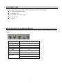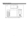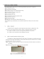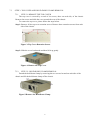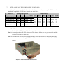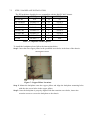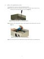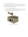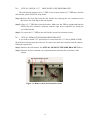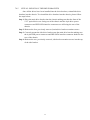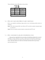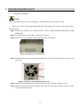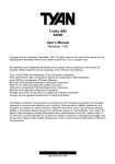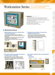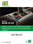
1
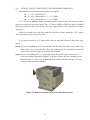
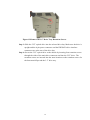
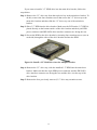
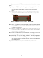
RACK-360G
4U Rackmount Chassis
USER’S MANUAL (V1.0)
健昇科技股份有限公司
JS AUTOMATION CORP.
新北市汐止區中興路 100 號 6 樓
6F., No.100, Zhongxing Rd.,
Xizhi Dist., New Taipei City, Taiwan
TEL:+886-2-2647-6936
FAX:+886-2-2647-6940
http://www.automation.com.tw
http://www.automation-js.com/
E-mail:[email protected]
CONTENTS
1.
2.
3.
4.
5.
6.
7.
FORWARD ....................................................................................................................................2
ABOUT THE RACK-360G...........................................................................................................2
SPECIFICATIONS ........................................................................................................................2
PACKING LIST.............................................................................................................................3
DETAILS OF INCLUDED SCREWS...........................................................................................3
DIMENSION DRAWING .............................................................................................................4
INSTALLATION STEPS ..............................................................................................................5
7.1
STEP 1: UNPACK..............................................................................................................5
7.2
STEP 2: FRONT HANDLE INSTALLATION ..................................................................5
7.3
STEP 3: TOP COVER AND HOLD-DOWN CLAMP REMOVAL ..................................6
7.3.1
STEP 3.1:REMOVE THE TOP COVER...............................................................6
7.3.2
STEP 3.2: HOLD-DOWN CLAMP REMOVAL ..................................................6
7.4
STEP 4: INSTALL THE POWER SUPPLY UNIT (PSU) .................................................7
7.5
7.6
7.7
7.8
8.
9.
STEP 5: BACKPLANE INSTALLATION.........................................................................8
STEP 6: CPU CARD INSTALLATION.............................................................................9
STEP 7: PCI/ISA EXPANSION CARD INSTALLATION................................................10
STEP 8: DISK DRIVES INSTALLATION........................................................................11
7.8.1
STEP 8.1: REMOVE THE SIDE BRACKET .......................................................11
7.8.2
STEP 8.2: INSTALL 3.5" DRIVES INTO THE SIDE BRACKET...................12
7.8.3
STEP 8.3: REMOVE THE MAIN DRIVE BRACKET ........................................12
7.8.4
STEP 8.4: INSTALL DRIVES INTO THE MAIN DRIVE BRACKET...............13
7.8.5
STEP 8.5: REINSTALL THE DRIVE BRACKETS .............................................17
7.9
STEP 9: FRONT PANEL CABLES ...................................................................................18
7.10 STEP 10: PSU CABLE AND INTERFACE CABLE CONNECTIONS ...........................19
7.11 STEP 11: HOLD-DOWN CLAMP AND COVER REINSTALLATION ..........................19
CHASSIS MAINTENANCE.........................................................................................................20
8.1
FAN REPLACEMENT ......................................................................................................20
8.2
FAN FILTER REPLACEMENT ........................................................................................21
Ordering Information.....................................................................................................................21
1
1. FORWARD
Thank you for your selection of RACK-360G 4U Rackmount Chassis
Any comment is welcome,
please visit our website: www.automation.com.tw for the up to date information.
2. ABOUT THE RACK-360G
The 4U, heavy-duty steel RACK-360Grackmount industrial chassis is designed industrial
environments where it will be exposed to dust, wide temperature variations, and shocks and vibrations,
among other things.
3. SPECIFICATIONS
Form Factor: Standard 4U, 19” wide
SBC Form Factor: Full-size, slot CPU cards
Construction: Heavy-duty steel
Slots Number: 14-slot (360G), 7-slot (360GATX)
Cooling(s): 1 x 12cm fan
Drive Bay Combinations:
3 x 5.25” Optical drives
2 x 5.25” Optical drives + 1 x 3.5” HDD (hard disk drive) + 1 x 3.5” FDD (floppy disk
drive)
2 x 5.25” Optical drives + 2 x 3.5” FDDs
Dimensions (DxWxH): 435.5mm x 431mm x 176mm
Operating Temperature : 0~40℃
Relative Humidity : 5~95%
Vibration :
5-17Hz, 0.1” double amplitude displacement
17-640Hz, 1.5G acceleration peak to peak
Shock : 10G acceleration peak to peak
2
4. PACKING LIST
When you unpack the chassis, make sure the following tems have been shipped.
1 x Quick Installation Guide
1 x Power Cord
2 x Handles and handle plates
1 x Screw Set
2 x Keys
5. DETAILS OF INCLUDED SCREWS
The attached screw set includes five types of screws. Screws used for chassis installation are shown
below.
1
2
3
4
5
Peripherals/Parts
Screw Labels in the Picture Above
5.25” Disk Drives
5
3.5” FDD
5
3.5” HDD
1
2.5” HDD
4
Power Supply Unit
1
Rackmount Bracket
3
Backplane
3
2
Table 1:Screws for Peripheral/Parts
3
6. DIMENSION DRAWING
The dimensions of RACK-360G are shown on the diagram below.
Figure 1: Dimension Drawing (measurement units: millimeter)
4
7. INSTALLATION STEPS
To install the RACK-360G chassis, the following installation steps must be completed:
Step 1: Unpack the chassis.
Step 2: Install the front handles.
Step 3: Remove the top cover and hold-down clamp.
Step 4: Install the PSU (power supply unit).
Step 5: Install the backplane.
Step 6: Install the CPU card.
Step 7: Install the PCI and ISA expansion cards.
Step 8: Install the disk drives.
Step 9: Connect the cables.
Step 10: Replace the hold-down clamp and the top cover.
The installation steps outlined above are described in detail below. Please refer to the relevant
section.
7.1
STEP 1: UNPACK
The RACK-360G is shipped in a plastic bag that is placed inside a cardboard box. The
accessories are also shipped with the chassis. When you unpack the chassis you must:
Make sure all the accessories and components listed above are present
Make sure the chassis has not been damaged in anyway.
7.2
STEP 2: FRONT HANDLE INSTALLATION
Two handles are shipped with the RACK-360G chassis. The handles are installed on the sides,
at the front of the chassis. Each handle is secured to the chassis by four retention screws. To install
the handles, please follow the steps below.
Step 1: Align the retention screw holes on the side of the chassis with the retention screw holes in
the handle.
Step 2: Insert and fasten four retention screws for each handle.
Figure 2: Front Handle Retention Screws
5
7.3
STEP 3: TOP COVER AND HOLD-DOWN CLAMP REMOVAL
7.3.1
STEP 3.1:REMOVE THE TOP COVER
The top cover is secured by a total of six screws, three on each side, of the chassis.
Remove the screws and slide the cover toward the rear of the chassis.
To remove the top cover, please follow the steps below.
Step 1: Remove all six top cover retention screws. Remove three retention screws from each
side of the chassis.
Figure 3: Top Cover Retention Screws
Step 2: Slide the cover backwards and then lift it up gently.
Figure 4: Remove the Top Cover
7.3.2
STEP 3.2: HOLD-DOWN CLAMP REMOVAL
Detach the hold-down clamp by removing the two screws located on each side of the
chassis and lift the hold-down clamp off the chassis.
Figure 5:Remove the Hold-Down Clamp
6
7.4
STEP 4: INSTALL THE POWER SUPPLY UNIT (PSU)
Once the top cover and hold-down clamp have been removed, a user supplied PSU must be
installed. Compatible IEI PSUs are listed in the table below.
Model No.
Input Type
Watt
Output Range
+3.3V
+5V +12V1 +12V2
-5V
-12V +5Vsb
ACE-940AP-RS
AC
AT
390W
N/A
40A
15A
N/A
0.3A
0.8A
N/A
ACE-832AP-RS
AC
ATX
300W
28A
30A
15A
N/A
0.3A
0.8A 2A
ACE-841AP-S-RS
AC
ATX
400W
28A
33A
20A
N/A
0.5A
1A
2A
ACE-850AP-RS
AC
ATX
500W
27A
29A
18A
18A
0.3A
0.8A
2A
ACE-R4130AP-RS
AC
ATX
300W
18A
25A
16A
N/A
0.5A
0.5A
2A
Table 2: Compatible IEI PSUs
The PSU is installed at the rear of the chassis and secured to the chassis with six retention
screws. To install the PSU, please follow the steps below.
Step 1: Correctly position the PSU at the rear of the chassis. Make sure the power switch and the
cable socket both face outwards.
Step 2: Once the PSU has been correctly positioned, secure the PSU to the chassis by inserting
two retention screws through the side, and four retention screws through the rear of the
chassis.
Figure 6: Insert PSU Retention Screws
7
7.5
STEP 5: BACKPLANE INSTALLATION
The IEI backplanes listed below are compatible with the RACK-360G chassis.
Model No.
SBC Type
PCI
ISA
PSU Type
ISA
N/A
14
AT
PCI-13SD-RS
PCIMG 1.0
3+4
3+3
AT/ATX
PCI-14S2-RS
PCIMG 1.0
4
8
AT/ATX
PCI-14S3-RS
PCIMG 1.0
4
9
AT/ATX
PX-14S3-RS
PCIMG 1.0
12
2
AT/ATX
PX-14S5-RS
PCIMG 1.0
7
5
AT/ATX
PCIAGP
11
N/A
AT/ATX
PICMG 1.3
4
0
ATX
BP-14S-RS
PXAGP-13S3-RS
PE-10S
Table 3: Compatible IEI Backplanes
To install the backplane please follow the instructions below.
Step 1: Insert the nine copper pillars in the predrilled screw holes in the base of the chassis.
Figure 7: Copper Pillars Locations
Step 2: Mount the backplane onto the copper pillars and align the backplane mounting holes
with the nine screw holes in the copper pillars.
Step 3: Once the backplane is properly aligned with the retention screw holes, insert nine
retention screws to secure the backplane to the chassis.
8
7.6
STEP 6: CPU CARD INSTALLATION
To install the CPU card please follow the instructions below.
Step 1: Remove the slot cover at the back of the chassis. To do this, remove the slot cover
retention screw at the top of the slot cover. (See Figure 8)
Figure 8: Remove the Slot Cover Retention Screw
Step 2: Slide the CPU card into the socket on the backplane reserved for the CPU card. (See
Figure 9)
Figure 9: Slide the CPU Card into the Sockets
Step 3: To secure the CPU card, reinsert the previously removed slot cover retention screw.S
9
7.7
STEP 7: PCI/ISA EXPANSION CARD INSTALLATION
The RACK-360G supports up to 14 PCI/ISA expansion cards and the RACK-360GATX
variant supports up to seven PCI/ISA expansion cards. To install an expansion card (PCI or ISA)
please follow the steps below.
Step 1:Remove the slot cover at the back of the chassis. To do this, remove the slot cover
retention screw at the top of the slot cover.
Step 2:Slide the PCI/ISA expansion card into reserved PCI/ISA socket on the backplane.
Step 3:To secure the PCI/ISA expansion card, reinsert the previously removed slot cover retention
screw.S
10
7.8
STEP 8: DISK DRIVES INSTALLATION
The RACK-360G chassis has two drive brackets: one main drive bracket and a side bracket.
The main drive bracket supports up to three 5.25” optical drives or two 5.25” drives and one 3.5”
drive (HDD or FDD). The side bracket only supports one 3.5” FDD drive To install the drives,
please follow the steps outlined in the sections below.
7.8.1
STEP 8.1: REMOVE THE SIDE BRACKET
Before any drives can be installed, the side bracket attached to the main drive bracket
must be removed. To remove the side bracket, remove the two retention screws from the top
of the side bracket that secure the side bracket to the main bracket.
Figure 10 : Remove the Side Bracket
11
7.8.2
STEP 8.2: INSTALL 3.5" DRIVES INTO THE SIDE BRACKET
The side bracket supports one 3.5” FDD. If you want to install a 3.5” FDD drive into the
side bracket, please follow the steps below.
Step 1:Remove the front flap from the side bracket by removing the two retention screws
that secure the front flap to the side bracket.
Step 2: Place a 3.5” FDD drive into the bracket. Make sure the FDD is upright and both the
IDE/SATA drive interface connector and the 4-pin power connector are facing the
rear of the bracket.
Step 3: To secure the 3.5” FDD to the side bracket, insert four retention screws.
7.8.3
STEP 8.3: REMOVE THE MAIN DRIVE BRACKET
If you wish to install 5.25” optical drives or more than one 3.5” drives (HDD or FDD),
the main drive bracket must be removed. To remove the main drive bracket from the chassis,
follow the steps below.
Step 1: Remove the side bracket. See STEP 8.1: REMOVE THE SIDE BRACKET above.
Step 2: Remove the four retention screws that attach the main bracket to the base of the
chassis.
Figure 11: Remove the Four Retention Screws
12
7.8.4
STEP 8.4: INSTALL DRIVES INTO THE MAIN DRIVE BRACKET
The main drive bracket has three bays that can support:
3 x 5.25” Optical drives
2 x 5.25” Optical drives + 1 x 3.5” HDD
2 x 5.25” Optical drives + 1 x 3.5” FDD
A 3.5” drive tray (HDD or FDD) is installed into the top drive bay. The two lower drive
bays are covered with two metal plates. The 3.5” drives (HDD or FDD) are always installed
in the drive bracket in the top drive bay. The 5.25” optical drives can be installed in all three
drive bays.
When you install drives into the main drive bracket, always install the 5.25” optical
drives into the two lower drive bays first.
If you want to install a 5.25” optical drive into the main drive bracket, follow the steps
below:
Step 1:If you are installing the 5.25” optical drive into the lower two drive trays, remove the
front metal covers from the drive bays by removing the four retention screws that
secure the front metal plates to the main drive bracket.
Step 2:If you are installing the 5.25” optical drive into the top drive bay, remove the 3.5”
drive tray from the main drive bracket. To do this, remove the four retention screws
that secure the 3.5” drive tray to the main drive bracket and then slide the 3.5” drive
tray out of the main drive bracket.
Figure 12: Remove the Front Metal Cover Retention Screws
13
Figure 13:Remove the 3.5” Drive Tray Retention Screws
Step 3: Slide the 5.25” optical drive into the selected drive bay. Make sure the drive is
upright and the 4-pin power connector and the IDE/SATA drive interface
connectors are at the rear of the drive bay.
Step 4: Secure the 5.25” optical drive to the chassis by inserting four retention screws
through the sides of the main drive connector and into the 5.25” drive. The
retention screws are inserted into the same locations as the retention screws for
the front metal flaps and the 3.5” drive tray. S
14
If you want to install a 3.5” HDD drive into the main drive bracket, follow the
steps below:
Step 1: Remove the 3.5” drive tray from the top drive bay in the main drive bracket. To
do this, remove the four retention screws that secure the 3.5” drive tray to the
main drive bracket and then slide the 3.5” drive tray out of the main drive
bracket.
Step 2: Place 3.5” HDD into the drive bracket. Make sure the PCB on the 3.5” HDD is
placed directly on the bottom surface of the drive bracket and the 4-pin HDD
power connector and IDE/SATA drive interface connector are facing the rear.
Step 3: Secure the HDD to the drive bracket by inserting four retention screws (two on
each side) through the sides of the drive bracket and into the HDD.
Figure 14: Install a 3.5” Disk Drive into the Adapter Bracket
Step 4: Reinsert the 3.5” drive tray, with the installed 3.5” HDD into the main drive
bracket. Make sure that the 4-pin HDD power connector and the IDE/SATA
drive interface connector are facing the rear and the drive is at the top of the
drive bracket.
Step 5: Reinsert the four, previously removed, 3.5” drive tray retention screws.
15
If you want to install a 3.5” FDD drive into the main drive bracket, follow the steps
below:
Step 1: Remove the 3.5” drive tray from the top drive bay in the main drive bracket. To
do this, remove the four retention screws that secure the 3.5” drive tray to the
main drive bracket and then slide the 3.5” drive tray out of the main drive
bracket.
Step 2: The front of the 3.5” drive tray is covered with a detachable metal cover. Use
your fingers to push the detachable cover inwards until the cover snaps off the
3.5” drive tray.
Figure 15: Bend off the front cover of the 3.5"drive bracket
Step 3: Place a 3.5” FDD drive into the bracket. Make sure the FDD is upright and both
the 4-pin FDD power connector and the IDE/SATA drive interface connector are
facing the rear of the bracket.
Step 4: Make sure the PCB on the 3.5” FDD is placed directly on the bottom surface of
the drive bracket and the 4-pin FDD power connector and the IDE/SATA drive
interface connector are facing the rear.
Step 5: Secure the FDD to the drive bracket by inserting four retention screws (two on
each side) through the sides of the drive bracket and into the HDD.
Step 6: Reinsert the 3.5” drive tray, with the installed 3.5” FDD into the main drive
bracket. Make sure that the 4-pin FDD power connector and the IDE/SATA
drive interface connector are facing the rear of the chassis and the FDD is at the
top of the drive bracket.
Step 7: Reinsert the four, previously removed, 3.5” drive tray retention screws.
16
7.8.5
STEP 8.5: REINSTALL THE DRIVE BRACKETS
Once all the drives have been installed into the drive brackets, reinstall the drive
brackets into the chassis. To reinstall the drive brackets into the chassis, please follow
the steps below:
Step 1: Place the main drive bracket into the chassis making sure that the front of the
5.25” optical drives are facing out of the chassis and the 4-pin drive power
connectors and IDE/SATA interface connectors are all facing the rear of the
chassis.
Step 2: Reinsert the four, previously removed, main drive bracket retention screws.
Step 3: Correctly mount the side drive bracket onto the main drive bracket making sure
the 4-pin FDD power connector and IDE/SATA interface connector both face the
rear of the chassis.
Step 4: Reinsert the two, previously removed, side bracket retention screws into the top
of the side bracket.
17
7.9
STEP 9: FRONT PANEL CABLES
The RACK-360G has the following components accessible at the front:
1 x Power LED
1 x HDD activity LED
1 x Power switch
1 x Reset button
2 x USB ports
1 x PS/2 keyboard/mouse
These components are all connected to the CPU card with cables. To correctly connect these
cables, please refer to the technical documentation that came with your CPU card. The connectors
that are provided with the chassis are listed below:
No.
Name
2
USB cable
1
KB cable
1
Power LED cable
1
Reset Switch cable
1
HDD LED cable
1
Power switch cable
Table 4: Chassis Connectors
18
The pin definitions for the USB cable are shown below.
PIN No.
Description
Color
1
+5V
Red
2
D-
Dark Yellow
3
D+
Yellow
4
GND
Brown
Table 5: Pin Definitions of USB Cable
7.10
STEP 10: PSU CABLE AND INTERFACE CABLE CONNECTIONS
Before you reinstall the hold-down clamp and the cover, the following cables need to be
connected.
Step 1: PSU cables from the PSU to the full-size CPU card, drives and the cooling fan must
be connected.
Step 2: The drive interface connectors must be connected to the CPU card.
7.11
STEP 11: HOLD-DOWN CLAMP AND COVER REINSTALLATION
After you have completed the above procedures, the hold-down clamp and cover can be
reinstalled. To do this, align the screw holes on both ends of the hold-down clamp with the
screw holes on both sides of the chassis and reinsert the four previously removed retention
screws. After that, slide the cover back over the chassis and reinsert the six previously
removed retention screws.
19
8. CHASSIS MAINTENANCE
8.1
FAN REPLACEMENT
NOTE:
Please ensure that the power of the computer is switched off before you replace a fan.
There is one 12 cm cooling fan inside the RACK-360G chassis. To replace a fan, please follow
the steps below.
Step 1: Remove the chassis cover. (Refer to STEP 3: TOP COVER AND HOLD-DOWN CLAMP
REMOVAl)
Step 2: Unplug the power cable that is connected to the fan.
Step 3: Remove the two retention screws at the top of the fan bracket.
Figure 16: Remove the Fan Bracket
Step 4: Pull the fan bracket out of the chassis and remove the four retention screws on each corner
of the fan.
Figure 17: Remove the Fan Retention Screws
Step 5: Replace the fan and secure the new fan to the bracket with four retention screws.
Step 6: Slide the bracket back into the chassis and secure it to the chassis with the four previously
removed retention screws. Step 0:
20
8.2
FAN FILTER REPLACEMENT
To replace the fan filter, please follow the steps below.
Step 1: Press the tab and pull the fan filter out to the right. (See Figure 18)
Figure 18: Remove the Fan Filter
Step 2: Replace the filter pad inside.
Step 3: Slide the fan filter back into the chassis.
9. Ordering Information
PRODUCT
JD55RACK360G
Matched Backplane
JD50088
JD55036
JD55044
DESCRIPTIONS
4U 14-slot Full-size Rackmount Chassis /USBx2 & PS2 on front
anel for easy accessibility / black, ATX POWER SWITCH
PX-14S5 14-Slots Backplane (7 PCI / 5 ISA / 2 PICMG)
PX-14S3 14-Slots Backplane (12 PCI / 1 ISA / 2 PICMG)
PXE-13S 13-Slots Backplane (8 PCI/ 1 PCIex16/ 3 PCIex1)
21