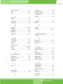
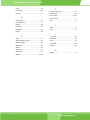
1
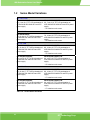
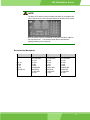
WS Series Industrial LCD User Manual Revision 1.0 February 2006 WS Workstation Series User Manual Revision History Title WS Series LCD Workstations User Manual Revision Number Description Date of Issue 1.0 Initial release March 2006 About This Manual This document covers the description and installation instructions for the WS series LCD workstations. The workstations in this series include the 10.4 inch WS-612GS, the 12.1 inch WS-843GS, the 15 inch WS-855GS and the 17 inch WS-875GS. Model variations will reflect the different implementation options, e.g., touch screen. Copyright Notice This document is copyrighted 2006, by IEI Technology Corp. All rights are reserved. IEI Technology Corp. reserves the rights to alter the products described in this manual at any time without prior notice. This document contains proprietary information protected by copyright. All rights are reserved. No part of this manual may be reproduced by any mechanical, electronic, or other means in any form without prior written permission of the manufacturer. Information provided in this manual is intended to be accurate and reliable. However, IEI Technology Corp. assumes no responsibility for use of this manual, nor for any infringements upon the rights of third parties, which may result from such use. 2 IEI® Technology Corp. WS Workstation Series Trademarks Intel is a registered trademark of Intel Corporation. AMI is registered trademarks of American Megatrends Inc. Other product names mentioned herein are used for identification purposes only and may be trademarks and/or registered trademarks of their respective owners. Packing List Before you begin installing your LCD workstation, please make sure that the following items have been shipped: 1 x WS series LCD workstation. 1 x AC Power Cord (cable type determined by the shipped-to area; one exemplary P/N: 32000-023200-RS). 1 x VGA cable (15-pin D-SUB male-to-male/180cm; P/N: 32000-023200-RS) 1 x screw kit (P/N: 19600-000148-RS) 1 x PS_ON cable for ATX signal (P/N: 32100-034801-RS; pre-installed) 1 x this User Manual in PDF format 7 x press stick rubbers (P/N: 47001-000101-RS) 3 x press stick kit (short; P/N: 41015-0004C0-00-RS) 4 x press stick kit (long; P/N: 41015-0003C0-00-RS) 1 x Installation, Utility, and Driver CD. 1 x RS-232 cable/touch pen/ Driver CD-ROM for touch screen (an optional item for the “T-R” models only; P/N: 32000-000050-RS) 1 x keypad/mouse pad PS/2 cable (P/N: 32000-000072-RS) 1 x keypad/mouse pad PS/2 cable (P/N: 32000-061400-RS; for ATX models) If any of these items are missing or damaged, you should contact your distributor or sales representative immediately. 3 WS Workstation Series User Manual Configuration Options Chassis coating/paint color options Touch screen options by specific “T-R” models RS-232 extension cable Safety Precautions 1. Prior to installing, moving, and modifying the workstation, make sure that the unit’s power is turned off and the power cord is disconnected. 2. Do not apply voltage levels that exceed the specified voltage range. Doing so will cause fire or an electrical shock. 3. Electric shock can occur if the panel is opened. Do not drop or insert any objects into the ventilation openings of the workstation. 4. Only qualified engineers from certified system integrators or VARs are allowed to make necessary functional modifications to the workstation, e.g., adding a touch screen. IEI offers the customization service on a pre-order basis. 5. For installations related to human safety, connect a separately installed mechanical switch instead of the workstation’s power switch. 6. Designs with stand-alone and fault-tolerant hardware considerations should be implemented using the series models as a critical alarm or production line control. 7. If considerable amount of dust, water, or fluids entered the workstation, turn off the power supply immediately, unplug the power cord, and contact your vendor. 8. Explosions may occur with installations in environments where flammable gases are present. 9. Fault-tolerant and failsafe designs should be implemented with the use of the series models on transportation vehicles, ships, safety/security devices, or medical devices not related to life-support functionalities. Users/integrators should take the responsibility for implementations with adequate levels of reliability and safety. 10. Preventive designs should be implemented so as to avoid the communications faults between the workstation and the PC/workstation/terminals that controls it. Precautions about Damages to the Workstation 1. Do not drop the workstation against a hard surface. Doing so will damage the display. 2. Do not strike or exert excessive force onto the touch panel. 4 IEI® Technology Corp. WS Workstation Series 3. Touching the touch panel using a sharp object will damage the LCD panel. 4. Avoid environments exposed to direct sunlight, dust, or chemical vapors. 5. The workstation is actively cooled. In no circumstances should the workstation operate with the openings obstructed by foreign objects. However, the ambient temperature of the installation site should be observed and controlled to avoid overheating the workstation. 6. Condensation might form inside the workstation chassis if exposed to sudden changes in temperature. 7. Carefully route the power cord so that people cannot step on it. Do not place anything over the power cord. 8. If the equipment should be left unused for an extended period of time, disconnect it from the power source to avoid damage by transient over-voltage. 9. If any of the following situations arises, get the equipment checked by service personnel: The power cord or plug is damaged. Liquid has penetrated into the equipment. The equipment has been exposed to moisture. The equipment does not work properly, or you cannot get it to work according to the user manual. The equipment has been dropped and damaged. The equipment shows obvious signs of breakage. WARNING! Any changes or modifications made to the equipment that are not expressly approved by the relevant standards could void your authority to operate the equipment. Additional Information and Assistance Maintain and Cleaning You need to note the following precautions before you begin to clean the LCD workstation. When you clean any single part or component of the computer, please read and understand the details below fully. 1. Except for the properly installed front LCD panel, never spray or squirt liquids directly onto 5 WS Workstation Series User Manual any computer component. If you need to clean the device, please rub it with a piece of dry and soft cloth or a slightly moistened cloth with the exterior casing. 2. The interior of the LCD workstation does not require cleaning. Keep fluids away from the LCD workstation and the interior of it. 3. Be cautious of the tiny removable components when you use a vacuum cleaner to absorb the dirt on the floor. 4. Turn the system off before you start to clean up the LCD workstation. 5. Never drop any tiny objects through the openings of the LCD workstation or get circuit board damp or wet. 6. Be cautious of all kinds of cleaning solvents or chemicals when you use it for the sake of cleaning. Some individuals may be allergic to the ingredients. 7. 6 Avoid any food, drink or cigarette around the LCD workstation. IEI® Technology Corp. WS Workstation Series Cleaning Tools Although many companies have created products to help improve the process of cleaning your computer and peripherals, users can also use household items to clean their computers and peripherals. Below is a list of items you may need or want to use while cleaning your computer or computer peripherals. Please keep in mind that some components in your computer may only be cleaned using a product designed for cleaning that component, if this is the case it will be mentioned in the cleaning tips. Cloth - A piece of cloth is the best tool to use when rubbing up a component. Although paper towels or tissues can be used on most hardware as well, we still recommend you to rub it with a piece of cloth. Water or rubbing alcohol – You may moisten a piece of cloth a bit with some water or rubbing alcohol and rub it on the computer. Unknown solvents may be harmful to the plastics parts. Vacuum cleaner - Absorb the dust, dirt, hair, cigarette particles, and other particles out of a computer can be one of the best methods of cleaning a computer. Over time these items can restrict the airflow in a computer and cause circuitry to corrode. Cotton swabs - Cotton swaps moistened with rubbing alcohol or water are excellent tools for wiping hard to reach areas in your keyboard, mouse, and other locations. Foam swabs - Whenever possible it is better to use lint free swabs such as foam swabs. ESD Precautions Observe all conventional anti-ESD methods while handling the components contained within the LCD should the need arise for adding a functionality. The use of a grounded wrist strap and an anti-static work pad is recommended. Avoid dust and debris or other static-accumulating materials in your work area. 7 WS Workstation Series User Manual Conventions Used in This Manual Naming From this point on and throughout the rest of this manual, the DM-170G series is referred to as simply the “LCD” or the “LCD workstation.” WARNING! Warnings appear where overlooked details may cause damage to the equipment or result in personal injury. Warnings should be taken seriously. Warnings are easy to recognize. The word “warning” is written as “WARNING,” both capitalized and bold and is followed by text in italics. The italicized text is the warning message. CAUTION! Cautionary messages should also be heeded to help you reduce the chance of losing data or damaging the system. Cautions are easy to recognize. The word “caution” is written as “CAUTION,” both capitalized and bold and is followed by text in italics. The italicized text is the cautionary message. NOTE: These messages inform the reader of essential but non-critical information. These messages should be read carefully as any directions or instructions contained therein can help you avoid making mistakes. Notes are easy to recognize. The word “note” is written as “NOTE,” both capitalized and bold and is followed by text in italics. The italicized text is the cautionary message. Lists Bulleted Lists: Bulleted lists are statements of non-sequential facts that can be read in any order. Each statement is preceded by a round black dot “•” or bullets in other shapes. Numbered Lists: Numbered lists describe sequential steps you should follow in order. 8 IEI® Technology Corp. WS Workstation Series Table of Contents REVISION HISTORY..................................................................................................................... 2 ABOUT THIS MANUAL ................................................................................................................ 2 COPYRIGHT NOTICE .................................................................................................................. 2 TRADEMARKS ............................................................................................................................. 3 PACKING LIST ............................................................................................................................. 3 Configuration Options ............................................................................................................... 4 SAFETY PRECAUTIONS ............................................................................................................. 4 Precautions about Damages to the Workstation....................................................................... 4 ADDITIONAL INFORMATION AND ASSISTANCE ..................................................................... 5 Maintain and Cleaning ..................................................................................................5 Cleaning Tools................................................................................................................7 ESD PRECAUTIONS .................................................................................................................... 7 CONVENTIONS USED IN THIS MANUAL .................................................................................. 8 TABLE OF CONTENTS ................................................................................................................ 9 CONTACT INFORMATION ..........................................................................................................11 CHAPTER ONE GENERAL INFORMATION 1.1 Introduction....................................................................................................................... 14 1.2 Series Model Variations ................................................................................................... 16 Recommended Backplanes........................................................................ 17 1.3 Specifications ................................................................................................................... 18 1.3.1 Hardware Specifications ............................................................................................ 18 1.3.2 LCD Display Specifications (Exemplary among Other Options) .......................... 20 1.3.3 Optional Touch Screen Specifications........................................................................ 24 1.3.4 Optional Mounting Kits ................................................................................................24 1.4 Product Dimensions......................................................................................................... 25 1.5 Comprehensive System Architecture............................................................................. 30 1.6 The AD Board.................................................................................................................... 31 CHAPTER TWO INSTALLATION Airflow Consideration .............................................................................................................. 36 Front Controls ......................................................................................................................... 37 9 WS Workstation Series User Manual 2.2 Workstation Installation ................................................................................................... 38 2.2.1 Accessing the Interior of the Workstation .................................................................. 38 2.2.2 Installing CPU Cards, Backplane, or Micro-ATX Main Board .................................... 39 2.4 Installing Peripheral Devices...................................................................................... 43 2.5 Cabling ....................................................................................................................... 46 2.6 Panel Mounting .......................................................................................................... 48 2.5 Rack Mounting .......................................................................................................... 49 CHAPTER THREE 3.1 OSD CONTROLS User Mode OSD Structure ............................................................................................ 52 Using the OSD ........................................................................................................................ 54 SOFTWARE DRIVERS Touch Panel Driver.................................................................................................................. 60 APPENDIX A ACCESSORIES Accessory List ......................................................................................................................... 68 10 IEI® Technology Corp. WS Workstation Series Contact Information IEI Technology Corp. 6F, No.29, Chung-hsing Rd., Sijhih City, Taipei Hsien 221, Taiwan Tel: +886-2-8691-6798 Fax: +886-2-6616-0030 E-mail: [email protected] 11 WS Workstation Series User Manual This page is intentionally left blank. 12 IEI® Technology Corp. WS Workstation Series Chapter 1 General Information 13 WS Workstation Series User Manual 1.1 Introduction The WS series is the latest member of IEI’s line of sophisticated LCD and chassis designs, and it has been improved to be RoHS compliant. The WS series is equipped with a 10.4/12.1/15/17 inch TFT type color LCD. The LCD screen itself features an MTBF up to 50,000 hours. With exceptional brightness, wide-view-angles, and fast response performance, the series is ideal for a wide range of applications. The WS LCD workstation series supports resolutions up to 1280(H) X 1024(V) pixels with 260,000 colors. For resolutions of other models, please refer to the following discussions. The WS LCD workstations are designed to fit Industrial automation or any applications that require the capabilities of working under harsh environmental conditions, minimum installation space, and flexible configurations. The front panel provides IP 64 protection which effectively ward off dust, oil, water, and vapors. Flexible analog interface is provided for ease of connection with an installed SBC (Single Board Computer) or Micro-ATX main board. Resistive or capacitive types of touch panels are provided as ordering options. If remote/non-attentive control is preferred, RS-232 or USB interfaces can be applied using customized adapter cables. The WS series does not restrict itself to the automation applications. Applicable solutions include the following: Any applications that requires HMI (Human Machine Interface) capabilities - Tough chassis - Front access membrane keypad and mouse pad ATE [Auto Test Equipment] 14 - Factory automation network nodes - Programmable machine controller IEI® Technology Corp. WS Workstation Series WS Series Workstations Comparison Chart Model WS-612GS WS-843GS WS-855GS WS-875GS LCD Size 10.4” 12.1” 15” 17” Max. Resolution 800X600 800X600 1024X768 1280X1024 Brightness (cd/M2) 230 400 350 400 Contrast 500:1 500:1 400:1 500:1 Color 262K 262K 262K 16.2M No. of Slots 7 10 10/m-ATX 10/m-ATX Compatible Card Form Factor Full size Full size Full size Full size Rack Height 6U 7U 8U 9U Front Panel Frame Aluminum alloy Aluminum alloy Aluminum alloy Aluminum alloy IP Level IP64 IP64 IP64 IP64 Chassis Heavy-duty steel Heavy-duty steel Heavy-duty steel Heavy-duty steel Keypad 63 keys 59 keys 59 keys 59 keys Function Keys Yes N/A N/A N/A Touch Pad Yes Yes Yes Yes Front Panel USB 4 2 2 2 1 1 1 5.25” Peripheral Bay N/A 3.5” Peripheral Bay 1 1 1 1 FDD Bay 1 1 1 1 Adapter/Power Supply (default) ACE-4525AP ACE-832AP ACE-832AP ACE-832AP Weight (NW/GW) 9.2/14.4kg 10.7/17.2kg 12/18.2kg 14.2/20.6kg Table 1-1: Series Models Comparison Chart 15 WS Workstation Series User Manual 1.2 Series Model Variations 6U – 10.4” LCD WS-612GS/4525AP: 6U, 7-slot 10.4" TFT LCD workstation w/ ACE-4525AP-RS 250W ATX and PFC power supply WS-612GS/4525AP/T-R: 6U, 7-slot 10.4" TFT LCD workstation w/ ACE-4525AP-RS 250W ATX and PFC power supply - 10” resistive touch screen 7U – 12” LCD WS-843GS/832AP: 7U, 10-slot 12" TFT LCD workstation w/ ACE-832AP-RS 300W ATX and PFC power supply WS-843GS/832AP/T-R: 7U, 10-slot 12" TFT LCD workstation w/ ACE-832AP-RS 300W ATX and PFC power supply - 12” resistive touch screen 8U – 15” LCD WS-855GS/832AP: 8U, 10-slot 15" TFT LCD workstation w/ ACE-832AP-RS 300W ATX and PFC power supply WS-855GS/832AP/T-R: 8U, 10-slot 15" TFT LCD workstation w/ ACE-832AP-RS 300W ATX and PFC power supply - 15” resistive touch screen WS-855GSATX/832AP: 8U, m-ATX 15" TFT LCD workstation w/ ACE-832AP-RS 300W ATX and PFC power supply WS-855GSATX/832AP/T-R: 8U, m-ATX 15" TFT LCD workstation w/ ACE-832AP-RS 300W ATX and PFC power supply - 15” resistive touch screen 9U – 17” LCD WS-875GS/832AP: 9U, 10-slot 17" TFT LCD workstation w/ ACE-832AP-RS 300W ATX and PFC power supply WS-875GS/832AP/T-R: 9U, 10-slot 17" TFT LCD workstation w/ ACE-832AP-RS 300W ATX and PFC power supply - 17” resistive touch screen WS-875GSATX/832AP: 9U, m-ATX 17" TFT LCD workstation w/ ACE-832AP-RS 300W ATX and PFC power supply WS-875GSATX/832AP/T-R: 9U, m-ATX 17" TFT LCD workstation w/ ACE-832AP-RS 300W ATX and PFC power supply - 17” resistive touch screen Table 1-2: Series Models Variations 16 IEI® Technology Corp. WS Workstation Series NOTE: The Micro-ATX and the multi-slot models only differ in the chassis side panel. Shown below is the side panel bracket of the Micro-ATX version. Note the airflow direction if additional cooling fans should be added to the side panel here. The holes as shown above should be the passage drawing in the cooling air. Recommended Backplanes WS-612 WS-843 WS-855 WS-875 PCI-7S PE-6S IP-7S BP-7S PCIAGP-6S PCI-10S/10S2 PX-10S PE-10S IP-10S IPX-9S PCIAGP-9S2 PXAGP-9S IP-10S/10S2 BP-10S PCI-10S/10S2 PX-10S PE-10S IP-10S IPX-9S PCIAGP-9S2 PXAGP-9S IP-10S/10S2 BP-10S PCI-10S/10S2 PX-10S PE-10S IP-10S IPX-9S PCIAGP-9S2 PXAGP-9S IP-10S/10S2 BP-10S Table 1-3: Recommended Backplanes for Series Models 17 WS Workstation Series User Manual 1.3 Specifications 1.3.1 Hardware Specifications In order to properly setup an LCD, it is recommended that you take a glimpse of the product specifications below before you proceed with installation. Front Panel Build Material Aluminum alloy; or painted/coated per customer’s request; IP 64 standard compatible with water- and moisture-proof engineering features Construction Chassis Robust steel SPCC t=1.2mm for demanding shock and vibration requirements LCD Display Type 17”, 15”, 12”, or 10.4” high brightness TFT LCD Display Resolution 17” LCD: 1280X1024 15” LCD: 1024X768 12.1” LCD: 800X600 10.4” LCD: 800X600 Display Connection Interface Analog VGA Brightness Front Control Various, up to 400 cd/m2 high brightness for industrial or out-door applications Front panel membrane keys Mouse pad, OSD function keys AD Board 17” and 15”: AV-5200/5300; 12.1”: AV-9261/AV5300; 10.4”: TBD Power Supply Options ATX 300W ACE-832A-RS ACE-832AP-RS ACE-832AP-S-RS 400W ACE-840A-RS ACE-841AP-S-RS 500W ACE-850AP-RS 600W ACE-4860AP-RS AT 300W ACE-932A-RS 350W ACE-935AL-RS 400W ACE-940AP-RS Mounting Options 19” rack options with specific accessories; Touch Screen Options Resistive type touch screen options Operating Temperature 0 to 50°C 18 IEI® Technology Corp. WS Workstation Series Related Humidity 5 to 95% Vibration 5-17Hz, 0.1” double amplitude displacement. 17-640Hz, 1.5G acceleration peak to peak. Shock 10G (1/2 sine, 11msec) Color Silver (Pantone PMS-8001 or any specified paint color) Dimensions 17” LCD: 483(W) x 398(H) x 268(D) mm; (see the dimensions for various models in the following discussion and the mechanical drawings) Protection IP-64 Environmental Friendliness RoHS compliant Ventilation One 12cm 2 ball bearing 99.6CFM fan Drive Bays 5.25” x 1, 3.5” x 1 internal and 3.5” x 1 front-accessible drive bays Table 1-4: General Hardware Specifications 19 WS Workstation Series User Manual 1.3.2 LCD Display Specifications (Exemplary among Other Options) 10.4” LCD (AUO): Size 10.4” Model G104SN05 Resolution H x V (pixel) 800 (R, G, B x 3) x 600 Pixel Pitch (mm) 0.264(H) x 0.264(V) Active Area (mm) 211.2(H) x 158.4(V) Pixel Pitch (mm) 0.264(H) X 0.264(V) Mode TN mode, normally white Number of Colors 262K Color Saturation (NTSC%) 45 View Angle (H/V) 120/100 Brightness (cd/m2) 230 Typ. (center) Contrast Ratio 500:1 Typ. Response Time (ms at 25°C) 35 Interface 1ch LVDS Backlight 1 CCFL (Cold Cathode Fluorescent Lampe) Table 1-5: 10.4” Display Specifications 20 IEI® Technology Corp. WS Workstation Series 12.1” LCD (AUO): Size 12.1” Model G121SN01 Resolution (pixel) SVGA (800 x 600) Active Area (mm) 246.0 x 184.5 Pixel Pitch (mm) 0.307 Mode TN Number of Colors 262K Color Saturation (NTSC%) 55 View Angle (H/V) 150/110 Brightness (cd/m2) 400 Contrast Ratio 500:1 Response Time (ms at 25°C) 35 Power Consumption (W) 7.3 Interface 1ch LVDS Supply Voltage (V) 3.3 Backlight 2 CCFL Lamp Life (hrs) 50,000 Table 1-6: 12.1” Display Specifications 21 WS Workstation Series User Manual 15” LCD (AUO): Size 15” Model G150XG01 Resolution (pixel) XGA (1024 x 768) Active Area (mm) 304.1 x 228.1 Pixel Pitch (mm) 0.297 Mode TN Number of Colors 262K Color Saturation (NTSC%) 60 View Angle (H/V) 130/120 Brightness (cd/m2) 350 Contrast Ratio 500:1 Response Time (ms at 25°C) 12 Power Consumption (W) 11.5 Interface 1ch LVDS Supply Voltage (V) 3.3 Backlight 2 CCFL Lamp Life (hrs) 50,000 Table 1-7: 15” Display Specifications 22 IEI® Technology Corp. WS Workstation Series 17” LCD (AUO): Size 17” Model M170EG01 V8 Resolution (pixel) SXGA (1280 x 1024) Aspect Ratio 5:4 Active Area (mm) 337.9 x 270.3 Pixel Pitch (mm) 0.264 Mode TN Number of Colors 16.2M Color Saturation (NTSC%) 72 View Angle (H/V) 140/130 Brightness (cd/m2) 300 Contrast Ratio 500:1 Response Time (ms at 25°C) 8 Power Consumption (W) 25.8 Interface 2ch LVDS Supply Voltage (V) 5 Backlight 4 CCFL Table 1-8: 17” Display Specifications 23 WS Workstation Series User Manual 1.3.3 Optional Touch Screen Specifications Type Resistive Resolution 4096 x 4096 dpi based on controller resolution Position Accuracy Less than 1.5% Light Transmission Anti-glare type: 78% to 90% Input Method Finger, Stylus, or gloved hand Temperature (typical) Operating: -10 to 60°C (8-wire: -40 to 85°C) Storage: -20 to 70°C (8-wire: -40 to 85°C) Surface Hardness 3H and above per JIS K5400 Electrostatic Protection Touch panel: 30KV (Contact/Air) Controller: 20KV (Contact/Air) Hitting: more than 10 million hits for 5-wire models Drawing: more 300K alphabets for 5-wire models Life Supported OSes Table 1-9: 24 Windows XP/XP embedded, Windows 2000, Windows ME, Windows 98SE, Windows CE.Net 4.2 (x86 and ARM), WHQL certified, Linux Fedora Core I/II, Mandrake 10.0/10.1, RedHat 9.0 Optional Touch Screen Specifications IEI® Technology Corp. WS Workstation Series 1.4 Product Dimensions Series Dimensions: 10.4” LCD Front panel: 483(W) x 266(H) x 248(D) mm (not including the spring screws) 12.1” LCD Front panel: 483(W) x 309.9(H) x 268(D) mm (not including the spring screws) 15” LCD Front panel: 483(W) x 352.9(H) x 261(D) mm (not including the spring screws) 17” LCD Front panel: 483(W) x 397.5(H) x 268(D) mm (not including the spring screws) Dimensions are measured not including the hand screws and the key lock on the front panel. Table 1-10: Product Series Dimensions 25 WS Workstation Series User Manual 17” Workstation Dimension Drawing: Figure 1-1: 26 WS Series Front Panel 17” LCD Dimensions IEI® Technology Corp. WS Workstation Series 15” Workstation Dimension Drawing: Figure 1-2: 15” LCD Dimensions 27 WS Workstation Series User Manual 12.1” LCD Dimension Drawing: F1 F2 F3 F4 F5 F6 F7 F8 F9 F10 Figure 1-3: 12.1” LCD Dimensions 28 IEI® Technology Corp. WS Workstation Series 10.4” LCD Dimension Drawing: Figure 1-4: 10.4” LCD Dimensions 29 WS Workstation Series User Manual 1.5 Comprehensive System Architecture The WS LCD workstation series is designed with considerations for the ease of integration featuring a modular design consisting an IP-64 aluminum LCD panel and a rugged steel chassis. Figure 1-5: Modular Design 30 IEI® Technology Corp. WS Workstation Series 1.6 The AD Board Figure 1-6: The AV-5300 AD Board Layout The AV-5300 AD board provides a wide variety of control interfaces, receiving and managing interface signals from the SBC or main board installed in the chassis. Some options, such as speakers and volume control, are currently not supported with the WS series LCD workstations. The AD board is secured to chassis and interfaced to the LCD panel through cabling. 31 WS Workstation Series User Manual Listed below are the pinouts of major functionality interfaces: 1. JP1 (1-2 default) Panel Power Input Selector Table 1-11: JP1 Pinouts PIN DESCRIPTION COMBINATIONS 1-2 +3.3V 3-4 +5V 5-6 +12V 2. JP2 (1-3, 2-4 default) Table 1-12: JP2 Pinouts PIN DESCRIPTION COMBINATIONS 1-3, 2-4 +12V input 3-5, 4-6 9N +36V input 3. CN5 OSD Control Table 1-13: CN5 Pinouts PIN DESCRIPTION COMBINATIONS 1 Red 2 +5V 3 Green 4 Menu 5 Down 6 Up 7 Auto 8 PWR 9 GND 4. CN6 Backlight Control Table 1-14: CN6 Pinouts PIN DESCRIPTION COMBINATIONS 1-2 +12V 3 BL-ON 4 BL-Bright 5-6 GND 32 IEI® Technology Corp. WS Workstation Series This page is intentionally left blank. 33 WS Workstation Series User Manual Chapter 2 Installation 34 IEI® Technology Corp. WS Workstation Series WARNING! The WS series LCD workstations must be installed and operated only by trained and qualified personnel. Maintenance, upgrade, or repair on the open device may only be RMA’ed or carried out by qualified personnel who are familiar with the associated dangers. Since the device may weigh more than 10 kg (not including a wall-mount bracket or accessories of the like), it is advisable to have another person assist in the installation. Make sure there is sufficient air circulation around the device and space for circulation outside the ventilation holes when installing the LCD workstation. The openings for cooling on the device (on the upper, side, and the back-end) must not be obstructed by objects or the like. If the ventilation holes are blocked, this can cause an overheating of the system. At least 5 cm of space free around the unit should be available to prevent the device from possibly overheating! The workstation should be properly grounded. The voltage feeds must not be overloaded. Adjust the cabling and provide external overcharge protection as noted by the electrical values indicated on the short description label attached to the back of the power supply module and to the chassis. Before the workstation is disassembled we strongly recommended that you should shut down the system and unplug the power cord. Electric shock and personal injury might occur if you access the components inside the workstation while the power cord is still attached. 35 WS Workstation Series User Manual Airflow Consideration As diagrammed below, the airflow travel through the workstation chassis from the ventilation holes on the interface panel and chassis rear-end through the cooling fan and power supply and exhaled to the outside. Care should be taken not to obstruct the airflow through the interior and around the chassis. Figure 2-1: 36 Airflow Direction IEI® Technology Corp. WS Workstation Series Front Controls Figure 2-2: Keypad and Mouse Pad The front access controls include a membrane keypad, power LED, OSD buttons, and a mouse pad. The OSD functions will be discussed in Chapter 3. The keypad interface is managed by a keyboard translator and the membrane keys function like a standard computer key board. The mouse pad functions like a standard AT mouse, and the function keys, the left- and rightbuttons, can be defined through the related driver included in kit. 37 WS Workstation Series User Manual 2.2 Workstation Installation The Touch Panel functionality comes as an optional implementation to the WS series. The workstations come with a membrane keypad and/or mouse pad and if extension display is desired, can connect to another VGA display via the included VGA interface on the side panel. 2.2.1 Accessing the Interior of the Workstation A variety of Micro-ATX boards or industrial PCI/ISA cards, SBCs can be installed into the WS series workstations. The Micro-ATX and multi-slot versions vary only in the side panel which either comes with interface slot brackets or rear-end brackets for multi-slot backplanes. Step 1. Use a flat-head screwdriver to unscrew and loosen the hand screws that secure the rear cover of the workstation chassis. Step 2. The rear cover is hinged to the bottom of the chassis. You may also remove the rear cover by removing the four pan head fasteners that secure it to the chassis. Figure 2-3: 38 Opening the Rear Cover IEI® Technology Corp. WS Workstation Series 2.2.2 Installing CPU Cards, Backplane, or Micro-ATX Main Board The series workstations adopt Micro-ATX form factor main boards or CPU cards mounted on PCI/ISA backplanes. The backplane and card options have been discussed in Chapter 1. The mounting holes inside the chassis readily receives the recommended Micro-ATX main boards or PCI/ISA cards. Install the included copper pillars to the standoffs. Secure these PCB to the associated mounting positions and use the hold-down clamp to secure the vertically installed cards. Care should be taken with the full-size cards which should be supported by the card holders that came with the fan module. Shown below is a 10-slot backplane installed in the chassis. Figure 2-4: Backplane Installation 39 WS Workstation Series User Manual Figure 2-5: SBC Installation NOTE: Align or reinstall the card guides on the fan module. Each card guide is secured to the fan module via two pre-drilled holes. When properly installed, the card guides secure the SBC card’s position within the chassis and is very important for system stability. Some of the SBCs may come with a large heatsink and cooling fan, therefore properly secure the SBC using the card guide and its slot bracket. Carefully route the interface cabling from the SBC to the chassis or peripheral devices. Use of cable ties is recommended and will help the ventilation flow within the chassis. Figure 2-6: 40 Hold-down Clamps IEI® Technology Corp. WS Workstation Series The chassis comes with two hold-down clamps. One is installed in the middle. The other secured to the top of the cooling fan module. Both clamps come with rubber foam that helps secure the SBC or extension cards within the chassis. Figure 2-7: Installing the Longer Hold-down Clamp One end of the longer hold-down clamp is locked on to the side of the chassis over a retainer socket. To install the card, align the end with a cut-out and make sure the protruding metal clip fit into the cut-out. Next secure the hold-down clamp by driving a screw through the hole on the other end to the 3.5” drive bay. If you need to install a floppy drive, install the hold-down clamp after you installed the 3.5” disk drives. 41 WS Workstation Series User Manual Figure 2-8: Installing the SBC Hold-down Clamp The shorter of the hold-down clamps is used to secure full-size cards such as CPU boards. Secure the hold-down clamp by fastening two retention screws to the holes on top of the cooling fan module. When installed, some cards may still fall short below the hold-down clamps. To better secure the SBC or expansion cards, you may use the included card clamps. First attach the included porons (which are self-adhesive) to the wider end of card clamps. Next locate the screw hole on the hold-down clamp closest to the target card. Adjust the card clamp in a vertical direction until a slight downward force is asserted onto the expansion card, and then fasten a panhead screw to secure the card clamp. With the poron, the card clamp functions as a shock absorber. 42 IEI® Technology Corp. WS Workstation Series Figure 2-9: Installing the Card Clamp 2.4 Installing Peripheral Devices The WS series provides space for the peripheral devices including one 5.25” and two 3.5” disk drives (one floppy and one hard disk drive). The 5.25” disk drive, usually a CD\DVD-ROM, and 3.5” floppy can be accessed through a front, water-resistant bezel door. Figure 2-10: Drive Bay Positions 43 WS Workstation Series User Manual Figure 2-11: Screw Positions at the Chassis Bottom Figure 2-12: 3.5” and 5.25” Drive Bays As shown above, the 3.5”, 5.25” drive bays, and the power supply module are secured through either 2 or 4 screws at the bottom of the chassis. Group A are holes securing the 5.25” drive bay. Group B are holes securing the 3.5” drive bay. Group C are the holes securing the power supply. To install a front-accessible disk drive, you need to remove the drive bays and then remove the 3.5” or 5.25” drive bay cover. You may also install another 3.5” hard drive to the 5.25” drive bay using separately-purchased brackets. Install peripheral devices by fastening them using the holes on the sides of the drive bays. Note that installing two hard disk drives into the 3.5” drive bay is not recommended. Stacking two hard drives tightly together may cause problems with heat dissipation. 44 IEI® Technology Corp. WS Workstation Series Figure 2-13: Power Supply Installation During the installation process, you might need to temporarily remove the power supply module. The power supply to secured to the chassis using two mounting screws at the bottom of the chassis, and another two screws at the rear end through an adapter bracket. Note that these two screws are different. One is the standard M3 pan-head screw while the other is a flathead screw. Installing the wrong screw will cause problems with closing the rear cover. NOTE: In installations where the water proof feature is required, always remember to properly lock the front bezel and close the rubber key lock end cap. Figure 2-14: Waterproof Endcap 45 WS Workstation Series User Manual 2.5 Cabling After the peripheral devices and CPU card/main board are installed, connect the signal bus cables and the associated power cords. In addition to the storage devices, connect the following: Internal Cabling 1. A 5-pin header for front bezel keypad and mouse pad. Please refer to the documentation that came with the associated CPU card/main board for the location of the keypad and mouse connector. 2. An 8-pin USB adapter cable to the USB ports on the front bezel. 3. Two 1-pin cables to the power switch. 4. One 4P power header that supplies power to the AD card (LCD panel adapter board). 5. One 4P power header that supplies power to the cooling fan module. NOTE: 1. The KB/MS 5-pin header is also routed to a PS/2 header on the side panel. 2. A 15-pin VGA cable is connected from the AD board to the side panel as the graphics input of the LCD display. The VGA interface is then connected via an included, 35cm, loop-back cable to the VGA interface of your SBC or Micro-ATX main board. If your workstation comes with a touch panel, connect the touch screen controller and your CPU card/main board through an RS-232 serial cable. External Cabling Connect the CPU card or main board VGA interface connector to the VGA connector on the side panel. 46 IEI® Technology Corp. WS Workstation Series Figure 2-15: Side Panel Cabling In addition to the membrane keypad on the front panel, an external keyboard or mouse can be connected to the workstation using a PS/2 adapter cable. A PS/2 connector can be located on the left side panel. There are two keypad/mouse interface connectors. You may either connect the internal 5-pin header cable to the SBC or main board if your SBC or main board comes with the corresponding interface. You may also connect the PS/2 interface connector on the side panel to the PS/2 connector on the SBC card’s rear bracket panel. The LCD display panel connects to the SBC or main board using a look-back VGA cable as shown above. Some WS workstations may come with an optional touch screen. You may then connect the serial port provided with the chassis to the SBC or main board’s serial port connector. 47 WS Workstation Series User Manual 2.6 Panel Mounting The WS series can be mounted within a panel. The workstation can be secured to a panel through the eight mounting holes on the sides of its front panel. Please make sure that the dimensions of the chassis is within panel aperture so that your screw holes line up with the mounting bolts on the flange of workstation. Figure -16: 2 48 Panel Mounting IEI® Technology Corp. WS Workstation Series 2.5 Rack Mounting The WS workstation series can be mounted to the rack posts of a standard 19” rack cabinet. Adequate rails, rack tray, or side brackets should also be available for supporting the weight of the workstation. Make sure that all cabling is correctly attached and carefully routed when installing the workstation. At least two persons are required for mounting the workstation, and a third person can help routing the cabling while inserting the workstation into the rack cabinet. Figure -17: 2 Rack Mounting the Workstation WARNING! 1. At least two persons are required to mount the workstation. 2. The rack cabinet into which the workstation is installed should provide adequate and sufficient ventilation, grounding, power source, and stability features. 49 WS Workstation Series User Manual This page is intentionally left blank. 50 IEI® Technology Corp. WS Workstation Series Chapter 3 OSD Controls 51 WS Workstation Series User Manual 3.1 User Mode OSD Structure Figure 3-1: OSD Buttons NOTE: Pressing the direction keys (LEFT or RIGHT) can bring out a simple menu which adjusts the LCD screen brightness and contrast values. Level 0 Level 1 Value Main Display Features Menu Brightness 0 to 100 Contrast 0 to 100 Horizontal Size 0 to 100 Phase 0 to 100 H. Position 0 to 100 V. Position 0 to 100 Sharpness 1 to 5 Volume This menu is currently disabled, and will be implemented with models equipped with audio speakers. Speaker Mute Color Menu 52 9300 - preset NTSC value 7500 - preset NTSC value User RGB values from 0 to 100 IEI® Technology Corp. WS Workstation Series Language Menu English Select French German Spanish Italian Japanese Russian Traditional Chinese Simplified Chinese OSD Menu Signal Menu OSD Time Out 0 to 60 sec OSD Position 1 to 5 OSD Transparency 0 to 100 Auto Setting On or Off Recall No or Yes Aspect Ratio 4:3 or 5:4 Digital Select Analog Backlight Menu Table 3-1: Light Enable On or Off Light Contrast 0 to 100 Light Brightness 0 to 100 Light H Start 0 to 100 Light H Width 0 to 100 Light V Start 0 to 100 Light V Height 0 to 100 OSD Menu Structure 53 WS Workstation Series User Manual Using the OSD Main Display Features Brightness The brightness option adjusts the brightness of screen. This function adjusts the offset value of ADC. Please mind that setting this value too high or too low will affect the quality of image. Contrast This function adjusts the gain value of ADC. Please mind that adjusting this value too high or too low will worsen the quality of image. Horizontal Size This item allows you to adjust the screen size in the Horizontal direction. Phase This option adjusts the input signal and dot clock position. (Analog only) H. Position Adjusts the horizontal position of the display screen V. Position Adjusts the vertical position of the display screen. Sharpness Adjusts the sharpness level to one of the 5 preset values. This option may help reducing the softening edges around displayed objects. 54 IEI® Technology Corp. WS Workstation Series Color This menu allows you to fine-tune the palette of color hues for your LCD. 9300 NTSC standard Kelvin 7500 NTSC standard Kelvin User This item allows you to fine-tune the balance among Red, Green, and Blue color hues if images look garish or unrealistic. Language This menu provides options for selecting ODS screen legends in a preferred language. 55 WS Workstation Series User Manual OSD Configuration OSD Time Out Determines how many seconds the OSD screen stays on screen before it disappears when OSD is left unattended. OSD Position Adjusts the OSD position on the screen. The position 1 is on the upper left of the screen, position 2 on the upper right, position 3 the center, and vice versa. OSD Transparency Determines the opaqueness of OSD background. Auto Setting This function automatically adjusts the LCD screen position in situations such as connecting the LCD to a different host computer. Recall Restores the default OSD settings. Note that this will restore all default display settings. Aspect Ratio Adjusts the display ratio referring to the width of the screen and then to the height of the screen. 56 IEI® Technology Corp. WS Workstation Series Signal This menu allows you to manually select the type of graphic source input, i.e., analog (15-pin VGA) or digital (DVI-D). Backlight Light Enabled Turns backlight on or off. Light Contrast Adjust the backlight contrast. Light Brightness Adjust the backlight brightness. Light H Start Adjusts the backlight projection area in the horizontal direction. Light H Width Adjusts the width of the backlight projection area. 57 WS Workstation Series User Manual Light V Start Adjusts the backlight projection area in the vertical direction. Light V Height Adjusts the size of backlight projection area in the vertical direction. 58 IEI® Technology Corp. WS Workstation Series Chapter 4 Software Drivers 59 WS Workstation Series User Manual Touch Panel Driver This touch panel controller provides the optimistic performance of analog resistive touch panels for four-wire, five-wire & eight-wire models. It communicates with PC system directly through the COM4 serial port interface. The design is superior in sensitivity, accuracy, and friendly operation. The touch panel driver emulates mouse left and right button function and supports operation systems including Microsoft Windows 95/98/ME/2000/NT/XP/XP Tablet PC Edition, Windows CE 2.12/3.0/. NET, Linux, iMac and DOS. To install the driver, locate the Touchkit driver folder in the utility CD that came your LCD. Select and open your OS sub-folder and double-click the Setup icon to start the installation program. The Touchkit welcome message should prompt. Click Next to continue. 60 IEI® Technology Corp. WS Workstation Series Your DM-170G series touch panel option is connected via serial port interface. You do not have to select the PS/2 option here. Click Next to continue. Select the Auto 4Pts Calibration Utility check box and click Next to continue. Click OK to proceed. 61 WS Workstation Series User Manual Click Next to skip this message. Provide an alternate destination folder or click Next to accept the default location. 62 IEI® Technology Corp. WS Workstation Series Provide a different name to be displayed in the program folder, or click Next to accept the default. The installation should now extract and copy files to the selected folder. 63 WS Workstation Series User Manual The installation program will then scan the available COM port connection. You will then be prompted to restart your system. You may choose to reboot later by selecting the No check box. Click Finish to continue. 64 IEI® Technology Corp. WS Workstation Series The Touchkit utility should start immediately allowing you to finish the initial setup. 65 WS Workstation Series User Manual This page is intentionally left blank. 66 IEI® Technology Corp. WS Workstation Series Appendix A Accessories 67 WS Workstation Series User Manual 6.1 Item Optional Accessory List Part No. Note Description 1 32000-000072-RS Keypad / MousePad PS/2 cable For all models 2 32000-061400-RS Keypad / MousePad PS/2 cable For ATX models 3 32000-000050-RS RS-232 cable / Touch Pen / Driver CD-ROM for touch screen connection For the “T-R” touch screen models Table A-1 Accessory List Listed above are the optional items and should be separately purchased. 68 IEI® Technology Corp. WS Workstation Series Index 69 WS Workstation Series User Manual 4P power header ........................................ 48 H. Position...................................................56 7500............................................................ 57 Hold-down Clamp........................................43 9300............................................................ 57 Hold-down Clamps......................................41 Horizontal Size ............................................56 A humidity.......................................................20 AD Board .................................................... 32 Airflow ......................................................... 37 I Aspect Ratio ............................................... 58 Installation ...................................................39 Auto Setting ................................................ 58 IP Level .......................................................15 B K Backlight ............................................... 55, 59 Keypad........................................................15 Backplane ...................................................40 Language ..............................................55, 57 Backplanes .................................................18 brightness ................................................... 19 Brightness............................................. 15, 56 L LCD Display Specifications .........................21 LCD Size .....................................................15 C Card Clamp................................................. 45 card clamps ................................................ 44 M Micro-ATX .............................................14, 40 card guides ................................................. 41 Model Variations .........................................17 Chassis ................................................. 15, 19 mounting .....................................................19 Cleaning Tools..............................................7 Color ............................................... 15, 54, 57 O Contrast ................................................ 15, 56 OP temperature...........................................20 CPU card .................................................... 48 Optional Accessory .....................................70 OSD ......................................................54, 55 D OSD Buttons ...............................................54 Dimension Drawing..................................... 27 OSD Configuration ......................................58 Dimensions .................................................26 OSD Position...............................................58 Display Features ......................................... 54 OSD Time Out.............................................58 Display type ................................................ 19 OSD Transparency .....................................58 Drive Bays .................................................. 20 P E ESD ..............................................................7 Panel Mounting ...........................................50 PCI/ISA cards..............................................40 Peripheral Bay.............................................15 F Peripheral Devices ......................................45 Front Control............................................... 19 Phase..........................................................56 Front Controls ............................................. 38 Power Cord ...................................................3 power supply ...............................................19 H 70 press stick .....................................................3 IEI® Technology Corp. WS Workstation Series User Manual PS/2 ............................................................ 49 T PS/2 cable .............................................. 3, 70 TFT type color LCD.....................................14 PS_ON..........................................................3 Touch Panel ................................................62 touch screen..........................................19, 70 R rack cabinet ................................................51 Touch screen ................................................4 T-R ................................................................4 Rack Mounting............................................ 51 Recall.......................................................... 58 U resolution ....................................................19 USB.............................................................15 Resolution................................................... 15 User ............................................................57 RoHS .......................................................... 20 V S V. Position ...................................................56 SBC ............................................................ 41 Ventilation ...................................................20 SBC Hold-down Clamp ............................... 44 VGA ............................................................48 Screw Positions .......................................... 46 VGA cable ...............................................3, 48 Sharpness................................................... 56 vibration ......................................................20 Shock.......................................................... 20 side panel ................................................... 18 Side Panel ..................................................49 W Weight .........................................................16 Signal.................................................... 55, 59 2 IEI® Technology Corp.