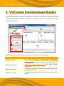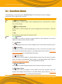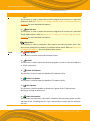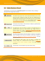
1
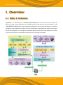
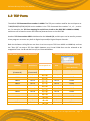
VxComm Driver/Utility User Manual Version 1.4, Apr. 2015 Includes a Kernel Driver that provides a Serial/COM Port Interface Supports PDS/DS/tDS/7188E/8000E Series Controllers Supports Windows XP Embedded System Supports 32/64-bit Microsoft Windows Built-in COM/TCP Terminal Program VxComm Driver/Utility User Manual WARRANTY All products manufactured by ICP DAS are warranted against defective materials for a period of one year from the date of delivery to the original purchaser. WARNING ICP DAS assumes no liability for damages consequent to the use of this product. ICP DAS reserves the right to change this manual at any time without notice. The information furnished by ICP DAS is believed to be accurate and reliable. However, no responsibility is assumed by ICP DAS for its use, nor for any infringements of patents or other rights of third parties resulting from its use. COPYRIGHT Copyright © 2015 by ICP DAS Co., Ltd. All rights are reserved. TRADEMARKS Names are used for identification purposes only and may be registered trademarks of their respective companies. CONTACT US If you have any questions, please feel to contact us by email at: [email protected] or [email protected] You will receive response within two working days. Copyright © 2015 ICP DAS CO., Ltd. All Rights Reserved. Page: 2 VxComm Driver/Utility User Manual TABLE OF CONTENTS 1. Overview ........................................................................................................... 4 1.1 What is VxComm ............................................................................................................................................... 4 1.2 TCP Ports ............................................................................................................................................................ 5 1.3 Support in ICP DAS Products .............................................................................................................................. 6 1.4 Windows Operating System Requirements ....................................................................................................... 7 2. Software Installation ......................................................................................... 8 2.1 Obtaining the Driver Installation Package .......................................................................................................... 8 2.2 Driver Installation Procedure ............................................................................................................................. 9 2.3 Uninstalling the Driver ..................................................................................................................................... 12 3. VxComm Environment Basics .......................................................................... 14 3.1 Functions Menu ............................................................................................................................................... 16 3.2 Main Button Panel ........................................................................................................................................... 18 3.2.1 Adding Servers .................................................................................................................................................. 19 3.3 Configure Servers Button ................................................................................................................................. 26 3.4 Configure Port Button ...................................................................................................................................... 30 4. Starting ........................................................................................................... 33 4.1 Searching a Device on an Ethernet Network ................................................................................................... 33 4.2 Configuring the correct Network Settings ....................................................................................................... 35 4.2.1 Single Device Server Configuration ................................................................................................................... 35 4.2.2 Multiple Device Servers Configuration ............................................................................................................. 37 4.3 Configuring the Virtual COM Ports .................................................................................................................. 41 4.4 Connecting to the Web Server for Device........................................................................................................ 43 5. Diagnostics ...................................................................................................... 44 5.1 Loopback Test .................................................................................................................................................. 44 5.1.1 Testing a TCP Port using the TCP/IP Port Terminal Program ............................................................................. 47 5.1.2 Testing a Virtual COM Port using the COM Port Terminal Program ................................................................. 49 5.2 Testing an External Device ............................................................................................................................... 51 6. Troubleshooting .............................................................................................. 55 6.1 COM Port Failed to Open ................................................................................................................................. 55 6.2 The Network Settings do not Work Correctly .................................................................................................. 57 Copyright © 2015 ICP DAS CO., Ltd. All Rights Reserved. Page: 3 VxComm Driver/Utility User Manual 1. Overview 1.1 What is VxComm "VxComm" is an abbreviation for "Virtual Communications Port". The VxComm Driver provides the ability to create Virtual COM ports in Windows and then map them to the serial ports on the 7188E/8000E/DS/PDS/tDS/iDS series of programmable device servers (Internet/Ethernet Controllers) through an Internet/Ethernet network. The only modification that needs to be made to any custom RS-232 client programs is to change the connection details so that the Virtual COM port is used to access the serial devices connected to the device servers through the network. Copyright © 2015 ICP DAS CO., Ltd. All Rights Reserved. Page: 4 VxComm Driver/Utility User Manual 1.2 TCP Ports The default TCP Command Port number is 10000. The TCP port number used for the serial ports on 7188E/8000E/DS/PDS/tDS/iDS series modules is the “TCP Command Port number" +1, +2 ..., and so on. For example, the TCP Port mapping for serial Ports 1 to 8 on the PDS-782 is 10001 to 10008, and these can be used to access the Ethernet/Internet Ports on the PDS-782. Another TCP Port number 9999 is dedicated to the Virtual I/O, and this port can be used by custom client programs to access any built-in Digital Input and/or Digital Output channels. Both the VxComm Utility/Driver use Ports 1 to N to map to TCP Ports 10001 to 10000+N, and use the "Port I/O" to map to TCP Port 9999. However, any Virtual COM Ports can be selected to be mapped to Ports 1 to N and the Port I/O, as illustrated below: 7188E/8000E/DS/PDS/tDS/iDS Module VxComm Utility/Driver on a PC TCP Port Serial Port Corresponds to Port Virtual COM Mapping (User-defined) 10000 (Command) Reserved (Command) - - - 9999 I/O Port I/O COM? 10001 Port 1 Port 1 COM? 10002 Port 2 Port 2 COM? 10003 Port 3 Port 3 COM? 10004 Port 4 Port 4 COM? 10005 Port 5 Port 5 COM? 10006 Port 6 Port 6 COM? 10007 Port 7 Port 7 COM? 10008 . . . 1000+N Port 8 . . . Port N Port 8 .. . Port N COM? . . . COM N Copyright © 2015 ICP DAS CO., Ltd. All Rights Reserved. Page: 5 VxComm Driver/Utility User Manual 1.3 Support in ICP DAS Products The following is a summary of serial device servers (Internet/Ethernet Controllers) produced by ICP DAS that support the VxComm Driver/Utility. Model 7188EN Series DS-700 Series 7186EX Series PDS-700 Series 8KE4, 8KE8 Series PDS-800 Series 8000E Series I8KE Series ET-6000, ET2-6000 Series PPDS-700-IP67 Series iPAC8K Series PPDS-700-MTCP Series ET-87Pn Series PDS-220FC/FCS/FT Series M-4132, M2M-7255, M2M-720-A Series PDS-5105D-MTCP Series M2M-710D/711D/712D Series tDS-700 Series M2M-520-AV ZB-257x Series GT-543 iDS-700 Series GRP-520, GRP-520P ZT-2570, ZT-7571 RMV-511/512/513, RMV-760-MTCP I-7547, I-7550-E Copyright © 2015 ICP DAS CO., Ltd. All Rights Reserved. Page: 6 VxComm Driver/Utility User Manual 1.4 W indows Operating System Requirements The following is an overview of the Microsoft Windows operating systems supported by the VxComm Driver/Utility. VxComm Utility VxComm98 VxComm2K Windows 2000 - Windows XP (32-bit) VxComm VxComm W7_V2.12.06_setup W7_V2.12.07_setup or later - - - - - Windows XP (64-bit) - - - Windows 2003 (32-bit) - - - Windows 2003 (64-bit) - - - Windows 2008 (32-bit) - - - Windows 2008 (64-bit) - - - Windows Vista (32-bit) - - - Windows Vista (64-bit) - - - Windows 7 (32-bit) - - - Windows 7 (64-bit) - - - Windows 2012 (32-bit) - - - - - Windows Windows 2012 (64-bit) Windows 8 (32-bit) - - - Windows 8 (64-bit) - - - Windows 10(32-bit) - - - Windows 10 (64-bit) - - - Note: Updates and support for the VxComm Driver/Utility are discontinued for Windows 95, Windows 98, Windows ME, Windows NT and Windows 2000. Copyright © 2015 ICP DAS CO., Ltd. All Rights Reserved. Page: 7 VxComm Driver/Utility User Manual 2. Software Installation The following is a detailed description of the process for obtaining, installing and removing the VxComm driver. 2.1 Obtaining the Driver Installation Package The installation package for the VxComm Driver can be obtained from the companion CD-ROM, the FTP site, or the ICP DAS web site. The locations and addresses are indicated below: 8000_CD: CD:\\NAPDOS\Driver\VxComm_Driver TinyModules_CD: CD:\\NAPDOS\Software\VxComm_Driver http://ftp.icpdas.com/pub/cd/8000cd/napdos/driver/vxcomm_driver/ ftp://ftp.icpdas.com/pub/cd/8000cd/napdos/driver/vxcomm_driver/ Install the appropriate driver for the current operating system, as indicated below: Folder Name VxComm Windows W7_v2.12.07_setup.exe or later 2k VxComm W7_v2.12.06_setup.exe Operating System 32/64-bit Windows XP, 32/64-bit Windows 2003, 32/64-bit Windows 2008, 32/64-bit Windows Vista, 32/64-bit Windows 7, 32/64-bit Windows 2012, 32/64-bit Windows 8 and 32/64-bit Windows 10 For Windows 2000 Copyright © 2015 ICP DAS CO., Ltd. All Rights Reserved. Page: 8 VxComm Driver/Utility User Manual 2.2 Driver Installation Procedure To install the VxComm driver, follow the procedure described below: Step 1: Double click the “VxCommW7_vx.xx.xx_setup” file icon to execute the driver installation application. Note: More recent operating system, such as Windows Vista and Windows 7, will display a warning message asking you to confirm whether you wish to install the software. Click the “Yes” button to continue. Step 2: Once the “Setup – VxComm Driver W7” Installation Wizard screen is displayed, click the “Next>” button to start the installation. Copyright © 2015 ICP DAS CO., Ltd. All Rights Reserved. Page: 9 VxComm Driver/Utility User Manual Step 3: Select the destination location. The default path is C:\ICPDAS\VxCommW7. Verify that the destination path is correct and click the “Next >” button, or click the “Browse…” button to install the driver in a different location. It is strongly recommended that the driver is installed in the default location. Step 4: Click the “Next >” button on the “Select Additional Tasks” screen to continue. Copyright © 2015 ICP DAS CO., Ltd. All Rights Reserved. Page: 10 VxComm Driver/Utility User Manual Step 5: Click the “Finish” button to complete the installation. Step 6: Once the installation is complete, the VxComm Utility will be opened automatically. Copyright © 2015 ICP DAS CO., Ltd. All Rights Reserved. Page: 11 VxComm Driver/Utility User Manual 2.3 Uninstalling the Driver The VxComm driver includes an uninstallation utility that allows the software to be removed from the computer if necessary. To uninstall the software, follow the procedure described below: Step 1: Click the Windows “Start” button and then click the “All programs”. Click the “ICP DAS” folder and then open the “VxCommW7” folder and click the “Uninstall VxComm Driver” item to run the uninstall process and remove the driver. Note: More recent operating system, such as Windows Vista and Windows 7, will display a warning message asking you to confirm whether you wish to allow software from an unknown publisher to make changes to the computer. Click the “Yes” button to continue. Copyright © 2015 ICP DAS CO., Ltd. All Rights Reserved. Page: 12 VxComm Driver/Utility User Manual Step 2: A dialog box will be displayed asking for confirmation that you want to remove the driver and utility program. Click the “Yes” button to continue. Step 3: After the uninstallation process is complete, a dialog box will be displayed to indicate that the driver was successfully removed. Click the “OK” button to finish the uninstallation process. Copyright © 2015 ICP DAS CO., Ltd. All Rights Reserved. Page: 13 VxComm Driver/Utility User Manual 3. VxComm Environment Basics Once the VxComm driver installation is complete, a shortcut to the VxComm Utility will be created on the Windows desktop. Double click the shortcut to open the VxComm Utility. Refer to the figure below for more details. The following is an overview of the main sections of the VxComm Utility interface. Item Functions Menu Main Button Panel Search-List Panel Server-List Panel Description This is the main menu of the Utility. Refer to Section 3.1 “Functions Menu” for more detailed information. This panel contains the main buttons for the Utility. Refer to Section 3.2 “Main Button Panel” for more detailed information. This panel shows detail of all devices connected to the same sub network as the PC. This panel shows details of the device servers that have been added. Copyright © 2015 ICP DAS CO., Ltd. All Rights Reserved. Page: 14 VxComm Driver/Utility User Manual Configure Server Button Port-List Panel Configure Port Button This button is used to configure the server settings. Refer to Section 3.3 “Configure Server Button” for more detailed information. This panel shows the mapping for the Virtual COM Ports and the configuration of a selected device server. This button is used to configure the port settings. Refer to Section 3.4 “Configure Port Button” for more detailed information. Copyright © 2015 ICP DAS CO., Ltd. All Rights Reserved. Page: 15 VxComm Driver/Utility User Manual 3.1 Functions Menu The following is an overview of the “functions menu” for the VxComm Utility, including a description of the usage of each function. Item Description File >> Import Configuration This function is used to import a new configuration from a specified file to replace the current settings. >> Export Configuration This function is used to export the current configuration of the device in .XML file format. Server >> Exit This function is used to quit the VxComm Utility. >> Ping Server This function is used to transmit a Ping command to check whether or not the IP address of a device server can be accessed. >> Diagnostic This is a Debug function that is used to diagnose the current status of a device server. >> Add Server(s) This function is used to add a specified device server to the Server-List panel, and is the same as the Add Server[s] button in the Main Button Panel. Refer to Section 3.2 “Main Button Panel” for more detailed information. >> Remove Server This function is used to delete a specified device server from the Server-List panel, and is the same as the Remove Server button in the Main Button Panel. Refer to Section 3.2 “Main Button Panel” for more detailed information. >> Remove All Servers This function is used to delete all device servers listed in the Server-List panel. >> Configure Server This function is used to configure a server listed in the Server-List panel, and is the same as the Configure Server button in the Main Button panel. Refer to Section 3.3 “Configure Server Button” for more detailed information. Copyright © 2015 ICP DAS CO., Ltd. All Rights Reserved. Page: 16 VxComm Driver/Utility User Manual Item Description Port >> Open COM Port This function is used to open the terminal program and connect to a specified COM port. Refer to Section 5.1.2 “Testing a Virtual COM Port using the COM Port Terminal” for more detailed information. >> Open TCP Port This function is used to open the terminal program and connect to a specified TCP/IP address/port. Refer to Section 5.1.1 “Testing a TCP Port using the TCP/IP Terminal” for more detailed information. Tools Configure Port This function is used to configure a Port listed in the Port-List panel, and is the same as the Configure Port button in the Main Button panel. Refer to Section 3.4 “Configure Port Button” for more detailed information. >> Restart Driver This function is used to restart the VxComm Driver. >> Terminal This function is used to open the terminal program in order to test the COM Port or TCP/IP connection. >> Modbus RTU Master This function is used to open the Modbus RTU Master Utility. >> Modbus TCP Master This function is used to open the Modbus TCP Master Utility. >> Driver Options This function is used to enable or disable the “Ignore Errors” feature when opening or writing to COM Ports. >> System Information This function provides basic information related to the operating system and the VxComm driver, including the CPU type, the VxComm version and the VxComm size, etc. Copyright © 2015 ICP DAS CO., Ltd. All Rights Reserved. Page: 17 VxComm Driver/Utility User Manual 3.2 Main Button Panel The following is an overview of the “main buttons panel” for the VxComm Utility, including a description of the usage of each function. Item Description The Add Server[s] button that is used to add specified device server to the Server-List panel. Clicking this button will open the “Adding Servers” dialog box which provides functions that allow items such as the IP Range, Server Options and Port Options, etc. to be configured. Refer to Section 3.2.1 “Adding Servers Window” for more detailed information. The Remove Server button. Click this button to delete a specified device server from the Server-List panel. The Web button. Click this button to connect to the Web Server for a specified device server via a web browser (e.g., Google Chrome or Internet Explorer, etc.). Refer to Section 4.4 “Connecting to the Web Server for a Device” for more detailed information. The Search Servers button. Click this button to search for any devices server connected to the same sub network as the Host PC. Refer to Section 4.1 “Searching for Devices on an Ethernet Network” for more detailed information. The Configuration [UDP] button. Click this button to configure the network settings for a specified device server. Refer to Section 4.2 “Configuring the Correct Network Settings” for more detailed information. The Exit button. Click this button to quit the VxComm Utility. Copyright © 2015 ICP DAS CO., Ltd. All Rights Reserved. Page: 18 VxComm Driver/Utility User Manual 3.2.1 Adding Servers The following is an overview of the “Adding Servers” dialog box for the VxComm Utility, including a description of the IP Range, Server Options and Port Options functions. 3.2.1.1 IP Range The following is an overview of the parameters contained in the “IR Range” tab of the Adding Servers dialog box: Server Name Get name automatically The VxComm driver can be configured to automatically retrieve name of a device server by checking the “Get name automatically” checkbox. If this option is disabled, however, a Server Name must be specified. If the server name doesn’t correspond to any device currently connected to the network, the following alert will be displayed. Copyright © 2015 ICP DAS CO., Ltd. All Rights Reserved. Page: 19 VxComm Driver/Utility User Manual IP Range Start IP Range End When adding a single device server, the IP address entered in the “IP Range Start” and “IP Range End” text fields will be the same. To add multiple device servers, the initial IP address for the range of devices must be entered in the “IP Range Start” text field and final IP address for the range of device servers must be entered in the “IP Range End” text field. If no addresses are entered in the IP range fields, the following alert will be displayed. Skip duplicated IP This option is used to determine whether or not duplicated IP address should be ignored. The default setting is to skip duplicated IP addresses. Disabling this option will mean that no check will be made to determine whether or not an IP address is already in the Server-List. If an IP address is duplicated, the following alert will be displayed. Includes the following special IP 0[Net], 254[Gateway], 255[Broadcast] If the “0*Net+, 254*Gateway+, 255*Broadcast+” options are enabled, these reserved IP addresses will be included when the VxComm Utility is instructed to add device servers. Copyright © 2015 ICP DAS CO., Ltd. All Rights Reserved. Page: 20 VxComm Driver/Utility User Manual COM Port This option is used to select an available Virtual COM to be used as Port1 on the VxComm server. Fixed baudrate, use current settings of servers Enabling the “Fixed Baud Rate, use current settings of servers” option can prevent a client from changing the Baud Rate. If multiple clients are connected to the same serial port, it is recommended that the serial port for the device server is configured via the web interface, and then this option can be enabled on all clients in order to prevent potential conflicts. Maps virtual COM ports to “Port I/O” on servers If a device has an I/O port, the “Maps virtual COM ports to Port I/O on servers” option can be enabled in order to map the I/O Port on the server. The Port I/O can also be manually remapped later. Copyright © 2015 ICP DAS CO., Ltd. All Rights Reserved. Page: 21 VxComm Driver/Utility User Manual 3.2.1.2 Server Options The following is an overview of the parameters contained in the “Server Options” tab of the Adding Servers dialog box: Keep Alive Time [Seconds] After connecting to the device server (e.g., a 7188E/8000E/DS/PDS/tDS/iDS series module, etc.), the VxComm Driver automatically sends a periodical command in order to keep the connection alive. The timer is reset following each successful send/receive command/data transmission. The “Keep Alive” mechanism doesn’t work until the next timeout. The default value for the “Keep Alive” time is about 120 seconds. The recommended value is (Device Server System Timeout * 1/3) or less. Connection Broken [Seconds] If the connection to the device fails, the VxComm Driver will automatically try to re-establish the connection. When the client sends a message to device server (e.g. a 7188E/8000E/DS/PDS/tDS/iDS series module, etc.), the VxComm Driver may receive with a "Disconnect" event from the Internet (TCP/IP) layer if the message is not sent after 20 seconds or more. To force the VxComm Driver to reconnect to the device server, a smaller “Connection Broken” time can be set (e.g., 180 seconds) in order to obtain a quicker response. Copyright © 2015 ICP DAS CO., Ltd. All Rights Reserved. Page: 22 VxComm Driver/Utility User Manual If no send/receive message has been transmitted on the connection before the “Connection Broken” timeout period has elapsed, the connection will be marked as having failed. As the VxComm Driver will also attempt to automatically re-establish the connection, the “Keep-Alive” time value should be smaller than the “Connection Broken” time value so as to ensure that the connection remains active. The default System Timeout (/STxxx) value for the device server (e.g., a 7188E/8000E/DS/PDS/tDS/iDS series module, etc.) is about 300 seconds. Once a client program has connected to the device server, a command must be sent by the client before the timeout elapses in order to keep the connection alive, otherwise the device server will reset itself, meaning that the client will need to re-establish a connection to the device server. To disable this mechanism, the “Keep Alive” time and the “Connection Broken” time can be set to 0. If these options are disabled, the System Timeout Value must also be set to 0 to disable the reset mechanism. Connect Timeout [Seconds] The “Connect Timeout” value will be passed to the MS TCP/IP driver for reference when connecting and disconnecting. Command Port [TCP] By default, the device server (e.g., a 7188E/8000E/DS/PDS/tDS/iDS series module, etc.) uses TCP port 10000 as the Command/Configuration port. If the device server settings are changed, the correct port must be assigned in the Command Port field so that the VxComm Driver can connect to the appropriate TCP port. This TCP port is used to configure the Baud Rate, Data Format, CTS/RTS control mode and Break, etc. Virtual I/O Port [TCP] By default, the device server (e.g., a 7188E/8000E/DS/PDS/tDS/iDS series module, etc.) uses TCP port 9999 as the Virtual I/O Port. If the device server does not contain any DI/DO channels, this TCP port is reserved. Copyright © 2015 ICP DAS CO., Ltd. All Rights Reserved. Page: 23 VxComm Driver/Utility User Manual 3.2.1.3 Port Options The following is an overview of the parameters contained in the “Port Options” tab of the Adding Servers dialog box: Disable purge command [e.g. ModScan32] When attempting to use the ModScan32 program to access or test a slave RTU device via a Virtual COM port, a communication timeout error may occur. This is because the ModScan32 program is purging (clearing) data from the serial port buffer too quickly after sending it, so the device server cannot finish sending the packets from the serial port before the data is purged, meaning that the slave device is unable to receive a full request packet. Consequently, no response will be received from the slave device and a timeout will occur. To resolve this issue, the “Disable purge command [e.g. ModScan32]” option can be enabled for all Virtual COM ports on the device. Note that this configuration will enable all Virtual COM Port on the device server. If a specific Virtual COM Port needs to be configured, refer to Section 3.4 “Configure Port Button”. Copyright © 2015 ICP DAS CO., Ltd. All Rights Reserved. Page: 24 VxComm Driver/Utility User Manual Enable Write-Buffer to collect small packets into big one Certain serial programs are only able to transmit one byte of data at a time, even if there is a large amount of data to be transmitted. This situation can cause a range of problems and leads to poor communication efficiency. If the "Enable Write-Buffer to collect small packets into big one" option is enabled, the driver will create a write-buffer for use by all the Virtual COM Ports of the device server, and will then merge each 1 byte packet written from the serial program into a single packet, which is then sent to the Ethernet in a single transmission, thereby improving the performance of the Ethernet communication. The timeout value for the write-buffer can be adjusted using the “Auto-Flush Interval” parameter (50 ms by default), so that if no more data is transmitted from the serial program within the specified interval, the accumulated data is combined into a single packet and immediately sent to the Ethernet. Note that this configuration will enable all Virtual COM Ports of the device server. If a specific Virtual COM Port needs to be configured, refer to Section 3.4 “Configure Port Button”. Copyright © 2015 ICP DAS CO., Ltd. All Rights Reserved. Page: 25 VxComm Driver/Utility User Manual 3.3 Configure Servers Button Once the “Add Server[s]” process is complete, the Configure Server button will be become available. Click the name of the device server to select it in the Server-List Panel to select it, and then click the “Configure Servers” button to open the “Server Configuration” dialog box. The following is an overview of the parameters contained in the “Server Option [PC]” tab of the Server Configuration dialog box: Keep Alive Time [Seconds] After connecting to the device server (e.g., a 7188E/8000E/DS/PDS/tDS/iDS series module, etc.), the VxComm Driver automatically sends a periodical command in order to keep the connection alive. The timer is reset following each successful send/receive command/data transmission. The “Keep Alive” mechanism doesn’t work until the next timeout. The default value for the “Keep Alive” time is about 120 seconds. The recommended value is (Device System Timeout * 1/3) or less. Copyright © 2015 ICP DAS CO., Ltd. All Rights Reserved. Page: 26 VxComm Driver/Utility User Manual Connection Broken [Seconds] If the connection to the device fails, the VxComm Driver will automatically try to re-establish the connection. When the client sends a message to device server (e.g. a 7188E/8000E/DS/PDS/tDS/iDS series module, etc.), the VxComm Driver may receive with a "Disconnect" event from the Internet (TCP/IP) layer if the message is not sent after 20 seconds or more. To force the VxComm Driver to reconnect to the device server, a smaller “Connection Broken” time can be set (e.g., 180 seconds) in order to obtain a quicker response. If no send/receive message has been transmitted on the connection before the “Connection Broken” timeout period has elapsed, the connection will be marked as having failed. As the VxComm Driver will also attempt to automatically re-establish the connection, the “Keep-Alive” time value should be smaller than the “Connection Broken” time value so as to ensure that the connection remains active. The default System Timeout (/STxxx) value for the device server (e.g., a 7188E/8000E/DS/PDS/tDS/iDS series module, etc.) is about 300 seconds. Once a client program has connected to the device server, a command must be sent by the client before the timeout elapses in order to keep the connection alive, otherwise the device server will reset itself, meaning that the client will need to re-establish a connection to the device server. To disable this mechanism, the “Keep Alive” time and the “Connection Broken” time can be set to 0. If these options are disabled, the System Timeout Value must also be set to 0 to disable the reset mechanism. Connect Timeout [Seconds] The “Connect Timeout” value will be passed to the MS TCP/IP driver for reference when connecting and disconnecting. Command Port [TCP] By default, the device server (e.g., a 7188E/8000E/DS/PDS/tDS/iDS series module, etc.) uses TCP port 10000 as the Command/Configuration port. If the device server settings are changed, the correct port must be assigned in the Command Port field so that the VxComm Driver can connect to the appropriate TCP port. This TCP port is used to configure the Baud Rate, Data Format, CTS/RTS control mode and Break, etc. Copyright © 2015 ICP DAS CO., Ltd. All Rights Reserved. Page: 27 VxComm Driver/Utility User Manual Virtual I/O Port [TCP] By default, the device server (e.g., a 7188E/8000E/DS/PDS/tDS/iDS series module, etc.) uses TCP port 9999 as the Virtual I/O Port. If the device server does not contain any DI/DO channels, this TCP port is reserved. IP Address [Primary] This textbox will display the current IP address of the device will be displayed. Redundant IP [Secondary] The default setting for the secondary IP address is 0.0.0.0. If a redundant IP is assigned, the VxComm Driver will connect to this IP address if the primary device server suffers a failure. Note that the values displayed for the “Keep Alive Time [Seconds]”, “Connection Broken [Seconds]”, “Connect Timeout [Seconds]”, “Command Port[TCP]” and Virtual I/O Port [TPC]” options will be the same as those entered in the “Server Options” tab of the Adding Servers dialog box. (See Section 3.2.1.2 “Server Options”) Copyright © 2015 ICP DAS CO., Ltd. All Rights Reserved. Page: 28 VxComm Driver/Utility User Manual The “Device Information” tab provides the basic details of the device server and other information related to the hardware and software, including the Model Name, the current Firmware/OS version number and date, the IP Address, the Sub-net Mask Address, the MAC Address, the Gateway Address, the TCP Port, the System Timeout, the Operation Mode, and Password Settings, etc. Copyright © 2015 ICP DAS CO., Ltd. All Rights Reserved. Page: 29 VxComm Driver/Utility User Manual 3.4 Configure Port Button Once the “Add Server[s]” process is complete, the Configure Port button will become available. Click the COM Port for the device server in the Port-List Panel to select it, and then click the “Configure Port” button to open the “Port Configuration” dialog box. The following is an overview of the parameters contained in the “Port Mapping [PC]” tab of the Port Configuration dialog box: Select COM The current Virtual COM Port number will be displayed. Select a valid COM port from the drop down menu to change which port is to be used. Note that the driver must be restarted each time the Virtual COM Port is modified. Click the “Tools” item in the “Functions” Menu, and then click “Restart Driver”. Copyright © 2015 ICP DAS CO., Ltd. All Rights Reserved. Page: 30 VxComm Driver/Utility User Manual Re-assign COM number for all subsequent ports If this option is enabled, the COM Port number can be re-assigned for all subsequent ports when the Virtual COM Port number is changed from the “Select COM” drop down menu. Fixed baud rate, use server current settings Enabling this option can prevent the client from changing the Baud Rate for the specified Virtual COM Port. If multiple clients are connected to the same serial port, it is recommended that the serial port of the device server is configured via the web interface, and then this option can be enabled on all clients in order to prevent potential conflicts. Disable purge command [e.g. ModScan32] When attempting to use the ModScan32 program to access or test a slave RTU device via a Virtual COM port, a communication timeout error may occur. This is because the ModScan32 program is purging (clearing) data from the serial port buffer too quickly after sending it, so the device server cannot finish sending the packets from the serial port before the data is purged, meaning that the slave device is unable to receive a full request packet. Consequently, no response will be received from the slave device and a timeout will occur. To resolve this issue this option can be enabled for the specified Virtual COM port. Enable Write-Buffer to collect small packets into big one If this option is enabled, the driver will create a write-buffer for use by the specified Virtual COM Port, and will then merge each 1 byte packet written from the serial program into a single packet, which is then sent to the Ethernet in a single transmission, thereby improving the performance of the Ethernet communication. The timeout value for the write-buffer can be adjusted using the “Auto-Flush Interval” parameter (50 ms by default), so that if no more data is transmitted from the serial program within the specified interval, the accumulated data is combined into a single packet and immediately sent to the Ethernet. Copyright © 2015 ICP DAS CO., Ltd. All Rights Reserved. Page: 31 VxComm Driver/Utility User Manual After opening the “Port Setting [Device]” tab, the VxComm Utility attempts to connect to the device server via a TCP connection in order to retrieve the current settings. If the settings are successfully retrieved by the VxComm Utility, the Baud Rate and Data Format values will be displayed in the relevant fields. Click the “Set to EEPROM/Flash *Device+” button to save the settings to the EEPROM of the device, as shown below. If the TCP connection is interrupted or a communication error occurs, the message "N/A" will be displayed in the Baud Rate filed. In this situation, the module may not be able to be configured, as shown below. Ensure that device server is online and that the IP configurations are correct, and then try again. Copyright © 2015 ICP DAS CO., Ltd. All Rights Reserved. Page: 32 VxComm Driver/Utility User Manual 4. Starting This chapter provides detailed information of how to use the VxComm Utility to correctly configure the Ethernet network and the Virtual COM Ports, and how to add a device server (e.g., a 7188E/8000E/DS/PDS/ tDS/iDS series module, etc.). 4.1 Searching a Device on an Ethernet Network Step 1: Ensure that the network settings on the Host PC are configured correctly. Ensure that the Windows firewall or any Anti-Virus firewall software is correctly configured. Alternatively, temporarily disable these functions, otherwise the “Search Servers” function in the VxComm Utility may not work as desired. Contact the System Administrator for details if unsure of how to do this. Step 2: Connect both your device (e.g., the PPDS-755D-MTCP) and the Host computer to the same sub-network or to the same Ethernet Switch, and then power on the device (e.g., the PPDS-755D-MTCP). Copyright © 2015 ICP DAS CO., Ltd. All Rights Reserved. Page: 33 VxComm Driver/Utility User Manual Step 3: Open the VxComm Utility and click the “Search Servers” button to search for the device server (e.g., the PPDS-755D-MTCP). The settings for the device server will be displayed in the Search-List Panel. The following are the factory default settings: IP Address 192.168.255.1 Subnet Mask 255.255.0.0 Gateway Address 192.168.0.1 DHCP OFF Copyright © 2015 ICP DAS CO., Ltd. All Rights Reserved. Page: 34 VxComm Driver/Utility User Manual 4.2 Configuring the correct Network Settings 4.2.1 Single Device Server Configuration Step 1: In the Search-List panel (see Section 4.1 “Searching for Devices on an Ethernet Network”), click the name of the device server (e.g., the PPDS-755D-MTCP) to select it. Step 2: Click the “Configuration [UDP]” button to open the “Configure Server (UDP)” dialog box. Step 3: Enter the network settings in the “Configure Server (UDP)” dialog box and then click the “OK” button. If these settings are unknown, contact the Network Administrator to obtain the correct network configuration details, such as IP/Mask/Gateway Addresses, etc. The new settings for the device server will become effective within two seconds. Copyright © 2015 ICP DAS CO., Ltd. All Rights Reserved. Page: 35 VxComm Driver/Utility User Manual Step 4: Wait for two seconds and then click the “Search Servers” button again to verify that the device server (e.g., the PPDS-755D-MTCP) is operating correctly using the new configuration. Step 5: Right-click the name of the device server in the Search-List panel and then select the “Ping Server” item from the shortcut menu. Step 6: A Command Prompt window will be displayed indicating the status of the ping command. If the response contains the message “Reply from” together with the IP Address of the device server, it indicates that the device server can be accessed and is operating correctly. Copyright © 2015 ICP DAS CO., Ltd. All Rights Reserved. Page: 36 VxComm Driver/Utility User Manual 4.2.2 Multiple Device Servers Configuration Note that this function is supported by VxComm Utility Version 2.13.00 [Mar. 26, 2015] or later. Step 1: In the Search-List panel (see Section 4.1 “Searching for Devices on an Ethernet Network”), press the “Ctrl” key and click the name of multiple device servers (e.g., the PPDS-755D-MTCP, tDS-718 and tSH-725 modules) to select it. Step 2: Click the “Configuration [UDP]” button to open the “Configure Server (UDP)” dialog box. Step 3: Enter the network settings in the “Preview List” panel of “Configure Server (UDP)” dialog box and then click the “OK” button. If these settings are unknown, contact the Network Administrator to obtain the correct network configuration details, such as IP/Mask/Gateway Addresses, etc. The new settings for the device server will become effective within two seconds. The “Configure Server (UDP)” dialog box provides 2 methods of configuring the network settings: batch and manual, follow the procedure described below: Copyright © 2015 ICP DAS CO., Ltd. All Rights Reserved. Page: 37 VxComm Driver/Utility User Manual Batch Editing in Network Settings 1. Assign a valid the network settings in the DHCP, IP Address, Sub-net Mask, Gateway and Alias text fields. 2. Click the “Copy Settings” button, it can reassign network settings to every module sequentially according to the Value in step 1. 3. Verify that the network settings can be re-assigned for all subsequent device servers are correct. 4. Click the “OK” button to save the settings. Copyright © 2015 ICP DAS CO., Ltd. All Rights Reserved. Page: 38 VxComm Driver/Utility User Manual Manual Editing in Network Settings 1. Click on the DHCP, IP Address, Sub-net Mask, Gateway or Alias in the “Preview List” section. 2. Enter the correct network settings. 3. Click the “OK” button to save the settings. Copyright © 2015 ICP DAS CO., Ltd. All Rights Reserved. Page: 39 VxComm Driver/Utility User Manual Step 4: Wait for two seconds and then click the “Search Servers” button again to verify that the device servers (e.g., the PPDS-755D-MTCP, tDS-718 and tSH-725 modules) is operating correctly using the new configuration. Step 5: Right-click the name of the device servers in the Search-List panel and then select the “Ping Server” item from the shortcut menu. Step 6: A Command Prompt window will be displayed indicating the status of the ping command. If the response contains the message “Reply from” together with the IP Address of the device server, it indicates that the device servers can be accessed and is operating correctly. Copyright © 2015 ICP DAS CO., Ltd. All Rights Reserved. Page: 40 VxComm Driver/Utility User Manual 4.3 Configuring the V irtual COM Ports Step 1: Click the name of the device server in the Search-List panel (e.g., the PPDS-755D-MTCP) to select it. Step 2: Click the “Add Server[s]” button to open the “Adding Servers” dialog box. Step 3: Assign a valid COM Port number from the COM Port drop down menu and then click the “OK” button to save the new settings. If the device server has a DI/DO port, check the “Maps virtual COM Ports to “Port I/O” on servers.” checkbox in the “Adding Servers” dialog box. This can be ignored if DI/DO ports are not being used, or they can be manually remapped later. Copyright © 2015 ICP DAS CO., Ltd. All Rights Reserved. Page: 41 VxComm Driver/Utility User Manual Step 4: Verify that all the settings for the added device servers and the mapped Virtual COM Ports in both the Server-List panel and Port-List panel are correct. Step 5: Click the “Restart Driver” item from the “Tools” menu. Then “VxComm Utility: Restarting Driver” dialog box will then be displayed. Step 6: Click the “Restart Driver” button to make the new settings effective. Copyright © 2015 ICP DAS CO., Ltd. All Rights Reserved. Page: 42 VxComm Driver/Utility User Manual 4.4 Connecting to the Web Server for Device Once the device server has been correctly configured and is operating normally on the network, connect to the Web Server in order to configure the advanced settings. Step 1: Click the name of the device server in either the Search-List panel or the Server-List panel (e.g., the PPDS-755D-MTCP) to select it. Step 2: Click the “Web” button to log into the web configuration pages for the device server. Copyright © 2015 ICP DAS CO., Ltd. All Rights Reserved. Page: 43 VxComm Driver/Utility User Manual 5. Diagnostics After correctly configuring the VxComm Driver using both the VxComm Utility and the web interface, the driver should be functioning correctly without any errors. However, a simple test can be conducted to ensure that the VxComm Driver is operating as expected. Note that the testing method depends on both the device server that is connected and the client programs that are being used. Here, the PPDS-755D-MTCP module is used as an example. For other device servers, refer to the specific Quick Start Guide or User Manual for that device server. 5.1 Loopback Test Step 1: Open the VxComm Utility and click the “Search Servers” button to search for any device servers (e.g., the PPDS-755D-MTCP) connected to the network. (See Section 4.1 “Searching for Devices on an Ethernet Network” for more details.) Step 2: Verify that the network settings and the Virtual COM Port for the device server are correct. (See Section 4.2 “Configuring the correct Network Settings” and Section 4.3 “Configuring the Virtual COM Ports” for more details.) Step 3: Log in to the web configuration pages for the device server. (See Section 4.4 “Connecting to the Web Server for Device” for more details.) Copyright © 2015 ICP DAS CO., Ltd. All Rights Reserved. Page: 44 VxComm Driver/Utility User Manual Step 4: From the Web Configuration interface, click the “COM Port Settings” link to display the Configure COM Port interface. Step 5: Click the “M0 (Transparent Mode)” option button in the “Operation Mode” section. Note: For more detailed information regarding the operation modes (M 0 to 3), refer to Section 4.3.1 “Operation Mode" in the User Manual for the PDS series. Step 6: Check the “Save current settings to EEPROM” and “Apply current settings” checkbox items, and then click the “SET COM PORT” button to complete the configuration. Step 7: Click the name of the device server in the Server-List panel of the VxComm Utility to select it, and then click the “Configure Servers” button to open the “Server Configuration” dialog box. Copyright © 2015 ICP DAS CO., Ltd. All Rights Reserved. Page: 45 VxComm Driver/Utility User Manual Step 8: In the “Server Configuration” dialog box, click the “Device Information” tab to confirm that the “Operation Mode” is shown as “0, Shared”, and then click the “OK” button to exit. Step 9: Connect the TxD pin to RxD pin (Port 1) on the device server (e.g., the PPDS-755D-MTCP). Copyright © 2015 ICP DAS CO., Ltd. All Rights Reserved. Page: 46 VxComm Driver/Utility User Manual 5.1.1 Testing a TCP Port using the TCP/IP Port Terminal Program Step 1: In the Port-List Panel of the VxComm Utility, right-click the Port1 entry for device server and select the “Open TCP Port” item from the shortcut menu. The TCP/IP Port Terminal program will then be opened. Step 2: Click the TCP/IP Port tab. Step 3: Enter the relevant IP address and TCP/IP Port information for the device server in the “IP Address” and “TCP/IP Port” fields, and then click the “Open TCP” button. Copyright © 2015 ICP DAS CO., Ltd. All Rights Reserved. Page: 47 VxComm Driver/Utility User Manual Step 4: Enter some characters (e.g., Virtual COM) in the “Send” field. Step5: Click the “Hex/Text” option in the “Display” section. Step6: Click the “Send” button to send the message. Step 7: Confirm that the characters displayed in the “Received” text field (e.g., Virtual COM) are the same as those entered in the “Send” text field. Step 8: Click the “Exit” button to close the TCP/IP Port Terminal program. Copyright © 2015 ICP DAS CO., Ltd. All Rights Reserved. Page: 48 VxComm Driver/Utility User Manual 5.1.2 Testing a V irtual COM Port using the COM Port Terminal Program Step 1: In the Port-List Panel of VxComm Utility, right-click the Port1 entry for the device server and select the “Open COM Port” item from the shortcut menu. The COM Port Terminal program will then be opened. Step 2: Click the COM Port tab. Step 3: Select the appropriate COM Port, Baud Rate and Data Format settings for the device from the relevant drop down menus, and then click the “Open COM” button. Copyright © 2015 ICP DAS CO., Ltd. All Rights Reserved. Page: 49 VxComm Driver/Utility User Manual Step 4: Enter some characters (e.g. Virtual COM) in the “Send” field. Step5: Click the “Hex/Text” option in the “Display” section. Step6: Click the “Send” button to send the message. Step 7: Confirm that the characters displayed in the “Received” text field (e.g., Virtual COM) are the same as those entered in the “Send” text field. Step 8: Click the “Exit” button to close the COM Port Terminal program. Copyright © 2015 ICP DAS CO., Ltd. All Rights Reserved. Page: 50 VxComm Driver/Utility User Manual 5.2 Testing an External Device Virtual COM Ports are mapped to the serial ports of the device server (e.g., the PPDS-755D-MTCP) by the VxComm Driver. Consequently, the DCON Utility can be used to search for remote I/O series modules (e.g., an M-7022) connected to the network through a Virtual COM Port. To test an external device connected via a Virtual COM Port, follow the procedure described below. Note that an M-7022 module and a PPDS-755D-MTCP server are used in this example: Step 1: Connect the M-7022 to Port2 (RS-485 bus) on the PPDS-755D-MTCP, and then attach a power supply to both the M-7022 and the PPDS-755D-MTCP. Step 2: Open the VxComm Utility and click the “Search Server” button to search for any device servers (e.g., the PPDS-755D-MTCP) connected to the network. (See Section 4.1 “Searching for Devices on an Ethernet Network” for more details.) Step 3: Verify that the network settings and the Virtual COM Port (e.g., COM3 to COM7) for the PPDS-755D-MTCP are correct. (See Section 4.2 “Configuring the correct Network Settings” and Section 4.3 “Configuring the Virtual COM Ports” for more details.) Copyright © 2015 ICP DAS CO., Ltd. All Rights Reserved. Page: 51 VxComm Driver/Utility User Manual Step 4: Install DCON Utility, which can be obtained from the companion CD-ROM, the ICP DAS FTP site, or the ICP DAS web site. The location of the installation files on the CD and the download addresses are shown below: CD:\\NAPDOS\Driver\DCON_Driver http://ftp.icpdas.com/pub/cd/8000cd/napdos/driver/dcon_utility/ Step 5: Open the DCON Utility, and click the “COM Port” item from the main menu to open the “Select the COM Port and Baud Rate…” dialog box. Copyright © 2015 ICP DAS CO., Ltd. All Rights Reserved. Page: 52 VxComm Driver/Utility User Manual Step 6: Select the Virtual COM Port that the M-7022 is connected to on the PPDS-755D-MTCP (e.g., COM4, RS-485 port) from the “Select COM to search” drop down menu. Step 7: Select the appropriate Baud Rate, Protocol, Checksum and Data Format settings from the relevant checkbox items. The exact values selected depend on the configuration of the M-7022. The following is an example: Baud Rate: “115200” and “9600” Protocol: “DCON” and “Modbus RTU” Checksum: “Disabled” and “Enabled” Parity: “None [N,8,1]” Step 8: Click the “OK” button to save the settings. Note: When working with an Ethernet/ Internet, there may sometimes be a slight delay on the network. As a result, it would possibly be better to set the timeout to a larger value, depending on the loading of the network. Step 9: Click the “Start Search” button to start searching for the M-7022, as illustrated below. Copyright © 2015 ICP DAS CO., Ltd. All Rights Reserved. Page: 53 VxComm Driver/Utility User Manual Step 10: Once the M-7022 is identified, it will be displayed in the search results panel of the DCON Utility. If the module name is displayed in the search results panel, it means that the module has been located and is operating normally. Step 11: Click the “Stop Search” button to stop the search. If the search is completed and the module is not displayed, it indicates that an error has occurred, either with the configuration or with the network. Check the connection and the configuration and try again. Note: For more detailed information regarding how to use the DCON Utility, refer to the DCON Utility User Manual. Copyright © 2015 ICP DAS CO., Ltd. All Rights Reserved. Page: 54 VxComm Driver/Utility User Manual 6. Troubleshooting 6.1 COM Port Failed to Open The COM Port that was created using the VxComm Driver fails to open in the client program. To resolve this issue, ensure that the network settings for both the host computer and the device are correctly configured. Check the power supply, the network cable, and the IP/Subnet Mask/Gateway address information for device server. If the correct network configuration information is unknown, contact the Network Administrator to obtain the details. Refer to the User Manual for device server (e.g., the 7188E/8000E/DS/PDS/ tDS/iDS series module, etc.) for more information. The COM Port still fails to open in the client program. Verify that the operating status for the VxComm Utility/Driver is normal, and then follow the procedure described below: Step 1: Open the VxComm Utility and then click the “System Information” item in the “Tools” menu to display the “System Information” dialog box. Copyright © 2015 ICP DAS CO., Ltd. All Rights Reserved. Page: 55 VxComm Driver/Utility User Manual Step 2: In the “System Information” dialog box, verify that the message “Driver is running” is shown in the “Status” field. If the status field indicates that the driver is not operating correctly, try restarting the driver by clicking the “Tools” item in the “Functions” Menu, and then clicking “Restart Driver”. If this doesn’t resolve the problem, uninstall the driver and then re-install and reconfigure it. See Section 2.3 “Uninstalling the Driver” and Section 2.2 “Driver Installation Procedure” for more details. The COM Port successfully opens in the client program, but the device cannot be accessed. Verify that the power supply and the RS-232/422/485 wiring for the device server are correctly configured. Refer to the User Manual for the device server (e.g., 7188E/8000E/DS/PDS/ tDS/iDS series module, etc.) for more information. Copyright © 2015 ICP DAS CO., Ltd. All Rights Reserved. Page: 56 VxComm Driver/Utility User Manual 6.2 The Network Settings do not Work Correctly Verify that the IP Address, Subnet Mask and Gateway Address are correct are correct for the current network. The factory default values for the IP Address, the Subnet Mask, and the Gateway Address for ICP DAS modules (e.g., 7188E/8000E/DS/PDS/ tDS/iDS series module, etc.) are 192.168.255.1, 255.255.0.0, and 192.168.0.1, respectively. If the IP Address, Subnet Mask or Gateway Address settings are not correct for the network being used, contact the Network Administrator to obtain a valid network configuration for the device server. Refer to Section 4.2 Configuring the correct Network Settings for more details. Note that incorrect settings will cause communication problems between the module and the network. Ensure that the IP Address is not currently being used by other devices. PDS Module Offline PDS Module Online Ping Timeout (No Reply) OK There are no IP address conflicts with other devices. Failure The PDS module does not work, the Ethernet cable is not properly connected or there is a problem with the network. Ping Success (Reply) Failure There is another device using the same IP address which has caused an IP conflict. OK The PDS module is functioning and responds to communications via the Ethernet. To resolve this issue, follow the procedure described below: Copyright © 2015 ICP DAS CO., Ltd. All Rights Reserved. Page: 57 VxComm Driver/Utility User Manual Step 1: Power off the device server and disconnect it from the network, and then send a “ping” command to the IP address of the device server. 1. Click the “Start” button and then click “Run” to open the “Run Command” dialog box. (If useing keyboard shortcuts, press the [Windows logo key] + [R] to open the Run Command dialog box.) 2. In the “Run Command” dialog box, type “cmd” in the “Open:” field and then click the “OK” button to open a Command Prompt window. Copyright © 2015 ICP DAS CO., Ltd. All Rights Reserved. Page: 58 VxComm Driver/Utility User Manual 3. In the Command Prompt window, type “ping” together with the “IP Address” of the device server (e.g., ping 10.0.8.100) and then press [Enter ]. If the response to the "ping" command is the message: "Request timed out", it is confirmation that the IP address is not currently being used by any other device. If the response to the “ping” command includes the message: "Reply from ....." along with the requested IP address, it indicates that the IP address is currently being used by another device. If the IP address is currently being used, refer to Section 4.2 “Configuring the correct Network Settings” to change the IP address in order to prevent future conflicts. Copyright © 2015 ICP DAS CO., Ltd. All Rights Reserved. Page: 59 VxComm Driver/Utility User Manual Step 2: Ensure that the device server is connected to the network and use the "Ping" command to test it. If the response to the “ping” command is the message: “Request timed out”, it means that the host was unable to connect to device server. Check the power supply, the network cable, network settings (IP Address, Subnet Mask and Gateway Address, etc.), and refer to the User Manual for device server. If the response to the “ping” command includes the message: “Reply from .......” along with the requested IP address, it indicates that the host has success fully established a connection to the device server. Copyright © 2015 ICP DAS CO., Ltd. All Rights Reserved. Page: 60