1
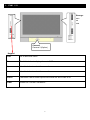
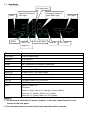
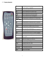
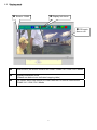
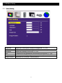
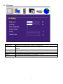
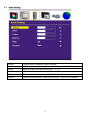
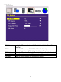
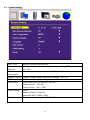
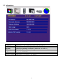
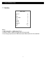
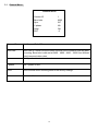
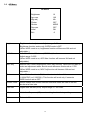
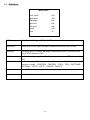
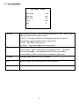
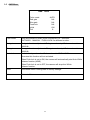
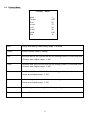
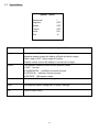
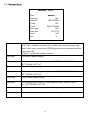
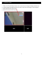
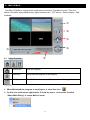
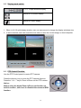
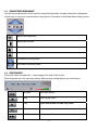
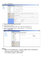
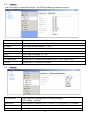
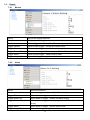
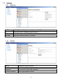
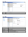
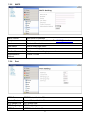
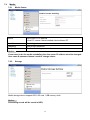
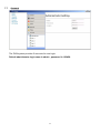
Thank you for purchasing our product.
Please read this User’s Manual before
using the product. Change without Notice
PVM
User’s Manual
Safety Precautions
CAUTION
RISK OF ELECTRICAL
SHOCK. DO NOT OPEN !
CAUTION: TO REDUCE THE RISK OF ELECTRICAL SHOCK,
DO NOT REMOVE COVER (OR BACK), NO USER
SERVICEABLE PARTS REFER SERVICING TO
QUALIFIED SERVICE PERSONNEL.
This label may appear on the bottom of the unit due to space limitations.
The lightning flash with arrowhead symbol, within an equilateral triangle, is
intended to alert the user to the presence of insulated dangerous Voltage
within the product’s enclosure that may be sufficient magnitude to constitute
risk of electrical shock to persons.
The exclamation point within an equilateral triangle is intended to alert the
user to the presence of important operation and maintenance (servicing)
instructions in the literature accompanying the appliance.
WARNING: TO PREVENT FIRE OR SHOCK HAZARD, DO NOT
EXPOSE UNITS NOT SPECIFICALLY DESIGNED FOR
Attention: installation should be performed by qualified service Personnel
only in accordance with the National Electrical Code or applicable local
codes.
Power Disconnect. Units with or without ON-OFF switches have power
supplied to the unit whenever the power cord is inserted into the power
source; however, the unit is operational only when the ON-OFF switch is
the ON position. The power cord is the main power disconnect for all
unites.
“CAUTION: Danger of explosion if battery is incorrectly replaced.
Replace only with the same or equivalent type recommended by the
manufacturer. Dispose of used batteries according to the manufacturer‘s
instruction.”
Warranty
and Service
During the warranty period (one year), we will repair or replace the DVR
free of charge.
Be sure to have the model number, serial number and vendor stick on
hard disk for service representative.
2
FCC Statement:
WARNING
This device complies with Part 15 FCC Rules. Operation is subject to the following two conditions: (1)
This device may not cause harmful interference. (2) This device must accept any interference
received including interference that may cause undesired operation."
* Federal Communications Commission (FCC) Statement
WARNING
This Equipment has been tested and found to comply with the limits for a Class B digital device,
pursuant to Part 15 of the FCC rules. These limits are designed to provide reasonable protection
against harmful interference in a residential installation. This equipment generates, uses and can
radiate radio frequency energy and, if not installed and used in accordance with the instructions, may
cause harmful interference to radio communications. However, there is no guarantee that interference
will not occur in a particular installation. If this equipment does cause harmful interference to radio or
television reception, which can be determined by turning the equipment off and on, the user is
encouraged to try to correct the interference by one or more of the following measures:
- Reorient or relocate the receiving antenna.
- Increase the separation between the equipment and receiver.
- Connect the equipment into an outlet on a circuit different from
that to which the receiver is connected.
- Consult the dealer or an experienced radio/TV technician for help.
* You are cautioned that changes or modifications not expressly approved by the party responsible for
compliance could void your authority to operate the equipment.
3
Contents
1.
1.1
1.2
1.3
1.4
2.
2.1
2.2
2.3
2.4
2.5
2.6
3.
3.0
3.1
3.2
3.3
3.4
3.5
3.6
3.7
3.8
4.
4.1
4.2
4.3
4.4
4.5
4.6
4.7
4.8
4.9
PVM
I/O............................................................................................................................ 6
REAR PANEL ........................................................................................................................................................................................................... 7
REMOTE CONTROLLER .................................................................................................................................................................................. 8
DISPLAY MODE ..................................................................................................................................................................................................... 9
DISPLAY MODE ..................................................................................................................................................................................................10
OSD MENU SETUP ........................................................................................................ 11
VIDEO SETUP .................................................................................................................... 11
PC SETTING ...................................................................................................................... 12
AUDIO SETTING ................................................................................................................ 13
PIP SETTING ..................................................................................................................... 14
SYSTEM SETTING .............................................................................................................. 15
INFORMATION .................................................................................................................... 16
CAMREA OSD MENU SETUP ...................................................................................... 17
MAIN MENU ....................................................................................................................... 17
GENERAL MENU ................................................................................................................ 18
AE MENU .......................................................................................................................... 19
WDR MENU ....................................................................................................................... 20
DAY / NIGHT MENU ............................................................................................................ 21
AWB MENU ....................................................................................................................... 22
PRIVACY MENU .................................................................................................................. 23
SPECIAL MENU .................................................................................................................. 24
MESSAGE MENU ................................................................................................................ 25
U
E-MAP FUNCTION SETUP............................................................................................. 26
DEVICE LIST .................................................................................................................... 27
ADD DEVICE .................................................................................................................... 27
ADD ALL DEVICE .............................................................................................................. 28
DELETE ALL DEVICE ......................................................................................................... 28
FULL SCREEN MODE .......................................................................................................... 28
MAIN UI MODE ................................................................................................................. 28
MAP MANAGEMENT ............................................................................................................ 28
NEXT MAP......................................................................................................................... 29
EXIT ................................................................................................................................. 29
5.
FULL SCREEN MODE.................................................................................................... 30
6.
MAIN UI MODE ............................................................................................................. 31
6.1 SETUP FUNCTION .............................................................................................................. 31
6.2 DISPLAY MODE SWITCH ..................................................................................................... 32
6.3 PTZ CONTROL FUNCTION ................................................................................................... 32
6.4 CAMERA COLOR ADJUSTMENT ............................................................................................ 33
6.5 PLAY FUNCTION................................................................................................................. 33
6.6 MEDIA FUNCTION SETUP .................................................................................................... 34
6.6.1 MEDIA SCHEDULE FUNCTION ......................................................................................... 35
6.6.2 EVENT LOG LIST ............................................................................................................ 41
6.6.3 SCHEDULE RECORD SETUP ............................................................................................ 42
4
7.
PVM FUNCTION CONFIGURATION .............................................................................. 43
7.1 SYSTEM ........................................................................................................................... 43
7.1.1 LANGUAGE ................................................................................................................... 43
7.1.2 DATE-TIME SETTING ...................................................................................................... 44
7.1.3 RESET ......................................................................................................................... 44
7.1.4 UPGRADE ..................................................................................................................... 45
7.1.5 REBOOT ....................................................................................................................... 45
7.1.6 INFORMATION ............................................................................................................... 46
7.1.7 FORMAT HDD................................................................................................................ 46
7.2 CAMERA .......................................................................................................................... 47
7.3 RECORD ........................................................................................................................... 47
7.4 EVENT .............................................................................................................................. 48
7.4.1 MOTION ...................................................................................................................... 48
7.4.2 ALARM ........................................................................................................................ 48
7.5 NETWORK ......................................................................................................................... 49
7.5.1 ETHERNET .................................................................................................................. 49
7.5.2 PPPOE ........................................................................................................................ 49
7.5.3 DNS ........................................................................................................................... 50
7.5.4 DDNS ......................................................................................................................... 50
7.5.5 SMTP .......................................................................................................................... 51
7.5.6 PORT .......................................................................................................................... 51
7.6 MEDIA ............................................................................................................................. 52
7.6.1 MEDIA CENTER ............................................................................................................. 52
7.6.2 STORAGE .................................................................................................................... 52
7.7 ACCOUNT.......................................................................................................................... 53
8.
MEDIA CONVERT ........................................................................................................... 54
5
1.
PVM
I/O
Storage:
HDD
SD
USB
Camera1
Camera 2 (Option)
Keypad
Enter
Go to sub-level menu.
Menu
Push this button to display the main OSD menu.
Up
Use this button to select the menu item.
Down
Use this button to select the menu item.
Source
The button use to select input source while the all of OSD is off.
Power
Power On / Off the PVM device .
6
1.1
Rear Panel
AV video input
DIDO
RS485
Camera1/Camera 2
MIC Input
VGA / DVI
Audio In
Camera1/Camera 2
Input (BNC type)
AV Audio Input
Ethernet
DVI Input
VGA Input
DVI Input
DVI Connector input
VGA Input
VGA Connector input
Ethernet
RJ45 Cable in
CAM1
BNC Connector for Camera 1 video input
CAM2
BNC Connector for Camera 2 video input
Video
AV video input
Audio (L)
AV audio input , RCA type (Left)
Audio (R)
AV audio input , RCA type (Right)
MIC 1 IN
The microphone audio in for camera 1
MIC 2 IN
The microphone audio in for camera 2
Line IN
The Audio Cable in for VGA / DVI
RS485
RS485 Connector for Speed Dome
DIDO
Alarm in / Alarm out
PIN define :
Alarm in 1 (red) , Alarm in 2 (orange), Ground (black)
Alarm out 1-1 (yellow), Alarm out 1-2 (blue)
Alarm out 2-1 (green), Alarm out 2-2 (purple)
Notice :
1. The front panel can build in Camera 2 (option) , it also can connect camera 1 and
Camera 2 from rear panel .
2. The rear panel cameras are the first priority than the build in cameras.
7
1.2
Remote Controller
Power
Use this button to turn the power on and off when
the main power is supplied
Cam1
Direct to select the internal camera source input
Cam2
Direct to select the extent camera source input
AV
Direct to select the AV source input
Media
Direct to select the media source input
VGA
Direct to select the VGA source input
DVI
Direct to select the DVI source input
PIP/POP
Use this button to adjust the PIP window size
Source
Use this button to select the PIP source input.
Video Swap
Use this button to swap the window ether main or
PIP.
Up
Use this button to select the menu of the item
Down
Use this button to select the menu of the item
Left
Use this button to adjust value of function.
Right
Use this button to adjust value of function.
Enter
Use this button to execute adjustment or to
select one item of next level.
CAM
Select the camera control (CAM1 or CAM2)
Mute
Mute the audio.
Info
Pop-out the source and DVR status message
Menu
Push this button to displays the main OSD menu.
Audio
Use this button to swap the live audio out ether
main or PIP.
Volume -
Adjust the volume down. (Zoom out)
Volume +
Adjust the volume up. (Zoom in)
Record
Start record or Stop
Scroll
Enable scroll text or Stop.
Play
Playback media from hdd
Stop
Stop playback
Repeat
Repeat current media
Previous
Go back previous media
Pause
Pause the playback
Next
Skip to next media
8
1.3
Display mode
n Source : CAM1
o Display Info Icons
p PIP mode
Source :AV
n
Main source ,the source could be the CAM1/ CAM2 / AV / VGA / DVI / Media
o
Display information Icons
(Please see below icons indicated mapping table ) .
p
PIP Mode, when main source is CAM1 then the PIP source could be the
CAM2 / AV / VGA / DVI / Media
9
1.4
Display Icon
Display Info (Icons indicated)
Camera 1 source active
Playing the media file
Camera 2 source active
Pause the playing media file
Camera 1 (No signal input )
Media source repeat file 1
Camera 2 (No signal input )
Media source repeat all files
AV source active
DVR recording
AV source (No signal input )
DVR stop record
Media source active
Audio Mute
Media source (No signal input )
Audio active
Client connected
HDD usage 0 %
Client disconnected
HDD usage 40 %
No audio signal input
HDD full (usage 100 %)
CDS control set on
Main source :CAM1
CDS control set off
PIP mode , PIP source:AV
10
2. OSD Menu Setup
2.1
Video Setting
Brightness
Adjusts the overall picture shade and brightness , 0 ~ 100
Contrast
Adjusts the contrast between light and dark areas of the picture. 0 ~ 100
Saturation
Adjusts the intensity of the color. 0 ~ 100
Hue
To determine the lightness and colorfulness of the picture, 0 ~ 100
Sharpness
Sets the desired sharpening enhancement to the picture 0 ~ 24
Image Position
adjustment for horizontal / vertical position
11
2.2
PC Setting
Brightness
Adjusts the overall picture shade and brightness.
Contrast
Permits adjustment of contrast between light and dark areas of the
picture.
Auto Adjustment Picture adjustment automatic correction, like clock and phase.
Image Position
Allows adjustment for horizontal / vertical position
Phase
To adjust the clock phase of VGA signal 0 ~ 31
Clock / Line
To adjust the H. total of VGA signal
12
2.3
Audio Setting
Volume
Controls built-in speakers’ output volumes.
Base
Adjusts the tone to low frequency part of the sound.
Treble
Adjust the high or acute of the sound. 0 ~ 14
Balance
Adjusts the softness of loudness of notes in the sound. -10 ~ +10
Mute
To disable the audio function.
Source
Select the audio source . (Main or sub source , only on PIP enabled)
13
0~ 14
(On / Off)
2.4
PIP Setting
PIP Mode
Select the PIP mode display , ( Off / Small / User / Side-by Side / Side-by
Side Tall )
PIP Source
Select the PIP source , ( CAM2 / DVI / VGA / Media / AV )
Note : main window and PIP window should be a different source .
PIP Position
Adjust the PIP position (Top-Left / Top-Right / Bottom- Right / Bottom- Left)
Sequential Time
Time of the video change the PIP source ( 0 ~ 100 seconds)
PIP Swap
Swap the source between the main and PIP window
14
2.5
System Setting
Date / Time
Setup the system date and time .
Auto Source
Detection
Auto detect source when the singal is lost (excluding PIP source)
(On / Off )
Color
Temperature
Selects color temperature of either 6500°K or 9300°K.
Channel Display Enable / Disable display the source message . (On / Off )
OSD Language
Select the OSD language. (English )
CDS Control
Power control by CDS function . (On /Off )
Power off level 100~300
Power on level 500 ~ 1000
CAM2 Setting
On/off
Protocol (Pelco P / Pelco D)
Baud Rate (2400 / 4800 / 9600)
Recall
Recall the user setting (ALL / DVR / LCD )
15
2.6
Information
IP Address
Display the PVM IP address. (default is 192.168.0.2)
Submask
Display the subnet mask. (default is 255.255.255.0)
Gateway
Display the gateway IP address. (default is 192.168.0.1)
HDD Usage
Display the hard disk record usage
DVR Version
Display the DVR F/W version
Monitor Version
Display the LCD monitor F/W version
16
3.
3.0
Camera OSD Menu Setup
Main Menu
Main menu
General
Ae
Wdr
Day / Night
Awb
Privacy
Special
Message
Initial
Exit
È
È
È
È
È
È
È
È
OFF
È
Notice :
1. CAM1 default ID is 1, CAM2 default ID is 2.
2. Switch to CAM1 or CAM2 will display with full screen mode.
3. Can’t change input source in CAM control mode. Must leave to the Live mode first.
17
3.1
General Menu
General menu
Camera ID
Baud rate
Sync
V phase
Initial
EXIT
1
9600
INT
NA
ON
È
Camera ID
Set Camera ID 1~255
Baud rate
Baud rate is a serial communication rate that use to measure how fast data
is moving. Baud rate is able set at 2400、4800、9600、19200 four different
serial communication rates.
Sync
Set Sync function to internal mode
V phase
Set V phase to N/A.
Initial
Initial General menu’s setting back to the factory settings
Exit
Return to Main menu
18
3.2
AE Menu
Ae menu
Brightness
Agc max
Mgc adj
Flicker
Shutter
Dss max
Initial
Exit
16
160
NA
OFF
MIRIS
OFF
ON
È
Brightness
Brightness level adjustment. Adjust range: 0~36.
Brightness function works only if WDR mode is OFF.
(When WDR mode is on, brightness function will become N/A and not
adjustable.)
AGC Max
Auto Gain Control Maximum (AGC Max) function.
Adjust range: 0~255.
(When WDR mode is on, AGC Max function will become N/A and not
adjustable)
MGC Adj
Manual Gain Control Adjustment (MGC Adj) function. Users are only able to
make an adjustment when Shutter mode becomes fixed such as 1/125.
(When WDR mode is on, MGC Adj function will become N/A and not
adjustable.)
Flicker
When Flicker function is ON, fixed electronic shutter will be
1/100(NTSC) or 1/120(PAL). This function will work only if camera’s
WDR function set as OFF.
Shutter mode
DSS max
MIRIS means auto shutter selected otherwise users are able to set the
shutter at a fixed rate
Digital Slow Shutter (DSS). Adjust range: 2~160 Field。
Initial
Initial Auto Exposure (AE) menu’s setting back to factory settings.
Exit
Return to Main menu
19
3.3
WDR Menu
WDR menu
Wdr mode
Wdr level
Backlight
Blc level
Blc wind
Initial
Exit
ON
128
NA
NA
NA
OFF
È
WDR mode
Wide Dynamic Range (WDR) ON/OFF switch
WDR level
When WDR is ON, users are able to adjust WDR level from 0 to 255.
Backlight
Backlight ON/OFF Switch. Backlight Compensation (BLC) function works
only if WDR function is OFF.
BLC level
BLC level setting range from 0 to 15, it only works when WDR function is
OFF
BLC wind
BLC wind setting. BLC wind function allows users set BLC wind position (10
positions in total).,CENTERS、CENTERL、TOPS、TOPL、BOTTOMS、
BOTTOML、LEFTS、LEFTL、RIGHTS、RIGHTL
Initial
Initial WDR menu’s setting back to factory settings.
Exit
Return to Main menu
20
3.4
Day / Night Menu
Day / Night
D/N mode
D/N level
D/N delay
Initial
Exit
D/N mode
menu
DAY
NA
NA
ON
È
Day / Night (D/N) mode,Users are able select AUTO、DAY、NIGHT three
different modes for the different needs.
(1) AUTO:According to D/N level and brightness level, camera will
automatically switches between Day or Night mode.
(2) DAY:Day Mode (Color picture).
(3) NIGHT:Night Mode (Black-and-white picture).
D/N level
When D/N mode set to AUTO, the camera will automatically switch
between Day or Night mode by detecting brightness level. When D/N
level is getting bigger,the brightness level of environment has to
become darker in order to make system switches to night mode.
D/N delay
Day/Night delay time is from 0~15 seconds.
Initial
Initial Day/Night menu’s setting back to factory settings.
Exit
Return to Main menu.
21
3.5
AWB Menu
AWB
menu
Color mode
Red gain
Blue gain
Push lock
Initial
Exit
AUTO
NA
NA
NA
ON
È
Color mode
Auto white balance (AWB) mode includes AUTO、INDOOR、
OUTDOOR、MANUAL、PUSH LOCK five different modes.。
Red gain
Red gain function adjustment. Red gain works only if Color mode set to
MANUAL.
Blue gain
Blue gain function adjustment. Blue gain works only if Color mode set to
MANUAL
Push lock
Push lock only works when Color mode set to PUSH LOCK
otherwise this function will not activated.
When Push lock is set to ON, the camera will automatically start Auto White
Balance function (AWB).
When Push lock is set to OFF, the camera will stop Auto White
Balance function.
Initial
Initial AWB menu’s setting back to factory settings.
Exit
Return to Main menu.
22
3.6
Privacy Menu
Privacy menu
Wind
Privacy
H str
H end
V str
V end
Initial
Exit
1
OFF
20
70
20
30
ON
È
Wind
Privacy area setting. Area setting range: 1~8 areas.
Privacy
Privacy function ON/OFF setting.
H str
Horizontal start is the function that set the starting position of horizontal level
in Privacy area. Adjust range: 1~180.
H end
Horizontal end is the function that set the ending position of horizontal level
in Privacy area. Adjust range: 1~180.
V str
Vertical start is the function that set the starting position of vertical level in
Privacy area. Adjust range: 1~120.
V end
Vertical ending is the function that set the ending position of vertical level in
Privacy area. Adjust range: 1~120.
Initial
Initial Privacy menu’s setting back to factory settings.
Exit
Return to Main menu.
23
3.7
Special Menu
Special
menu
Sharpness
Negative
Rotate
Freeze
Initial
Exit
7
OFF
OFF
OFF
ON
È
Sharpness
Sharpness level adjustment. Adjust range: 0~15.
Negative
When it sets to ON, Video image is Negative.
(Negative means screen will display in Black and white image)
When it sets to OFF, Video image is Positive.
(Positive means screen will display in normal color image)
Rotate
Four different modes provided for the different needs.
(1).OFF:Normal
(2).HORIZONTAL:Left/Right horizontal reverse.
(3).VERTICAL:Up/Down vertical reverse.
(4).ROTATE:180 degree rotates.
Freeze
When it set to ON , the screen Image freeze
Initial
Initial Special menu’s setting back to factory settings.
Exit
Return to Main menu.
24
3.8
Message Menu
Message
Zone
Zone disp
Zone pos
ID disp
ID pos
Zoom disp
Zoom pos
Initial
Exit
Zone
menu
■■■■■■
ON
LEFT DOWN
ON
RIGHT DOWN
ON
LEFT UP
OFF
È
Zone label setting,Maximum 16 characters.
※UP / DN – character selection (First, select Zone. And then press right
button. Last, users have to use UP/DN button to select characters that they
want to set with.)
※RIGHT – characters position selection
Zone disp
Zone screen display setting.
Zone pos
Zone display position,able adjust to RIGHT DOWN / RIGHT UP /
LEFT DOWN / LEFT UP
ID disp
ID screen display setting.
ID pos
ID display position setting,able adjust to RIGHT DOWN / RIGHT UP /
LEFT DOWN / LEFT UP。
Zoom disp
Zoom screen display setting.
Zoom pos
Zoom display position setting,able adjust to RIGHT DOWN / RIGHT
UP / LEFT DOWN / LEFT UP
Initial
Initial Message menu’s setting back to factory settings.
Exit
Return to Main menu.
.
25
4.
E-Map Function Setup
After run the E-Map function it will display a default map , user can setup camera on the map and
show each cameras location , user friendly interface design let user can see all cameras on the map .
Device list
List all cameras connection status
Add Device
Add a new camera on the Map
Add All Device
Add all cameras on the Map
Delete All Device
Delete all cameras on the Map
Full Screen Mode
Display with full screen mode
Main UI Mode
Display with UI mode
Map Management
Camera grouping management
Next Map
Change to next Map
Exit
Exit E-Map function
26
4.1 Device List
On the E-MAP user can move the camera icon to desire position, and the camera video window also
can use mouse to change windows size.
Device Info :
It shows all cameras list
status , when use mouse
click the device list again ,
the device info window will be
hidden .
The camera icon can
move to any position
4.2 Add Device
User can add a new camera on the map , it will display add device window .
IP address: input the camera’s IP address
User name : input login username
Password : input password
Location : descript the camera location
Port number :
default RTSP :554 , HTTP:80 ,Control :21
Notice :
Default username is admin ,
password is 123456
27
4.3 Add All Device
Add all cameras on the map that was auto discover on the device info window.
User can move the camera icon to any location.
4.4 Delete All Device
Delete all cameras on the map .
4.5 Full Screen Mode
Display all cameras with full screen . Press “ESC” button to exit Full screen.
4.6 Main UI Mode
Switch to the UI mode function .
4.7 MAP Management
User can use different map to manage cameras, user friendly design let user can setup group
cameras in each map .
28
use can add item , edit item , delete select item to setup cameras .
The small icon means IP
camera location , user can use
mouse move to any position .
Set to Root
When user add a new map , need press set to root
button
File Path
Select map
Channel select
Select camera
IP Address
The camera’s IP address , after user select channel it
will auto display
User Name
Input user name
Password
Input user password
Location
Camera location description
Description
Camera description
(BMP file format )
4.8 Next Map
Use this function to change map, it will change the map from map management database one
by one.
4.9 Exit
Quit the E-MAP program.
29
5.
1.
2.
3.
4.
Full Screen mode
When in 4,9,16 split display window, user can use mouse to change the display windows size.
In active window, user can record the live video or save the current image on local computer.
Save image file with JPEG format.
Record live video with AVI format.
30
6.
Main UI Mode
Use Main UI Mode to configure the media server functions , Playback function ,Time List
search ,Schedule setup,Media setup, Adjust camera color , PTZ control , Switch display , Split
windows .
c
d
e
f
g
6.1
h
Setup Function
Power Off
Quit the program.
Minimize
Minimized the program to working bar.
Configuration
The PVM function setup . (Please refer to the page 43 )
Notice :
1. When Minimized the program to working bar, it show this icon.
2. On this icon click mouse right button, it show the menu , choose this function
“Show Main Dialog” to return Main UI mode.
31
6.2
Display mode switch
1, 4, 9, 16 split windows display
Switch to Full screen display
Switch to E-MAP display
1. When in 4,9,16 split display window, user can use mouse to change the display windows size.
2. In active window, user can record the live video or save the current image on local computer.
6.3 PTZ Control Function
Use the PTZ Control panel to control PTZ camera.
Press the directory key to move the PTZ camera direction.
Press the “+”or “-“ key to Zoom in/Zoom out the PTZ camera .
Notice :
Before using the digital Zoom in/Zoom out function on
build in camera , user have to disabled the camera’s WDR
function.
32
6.4 Camera Color Adjustment
Use the color adjustment control panel to setup the brightness, contrast, saturation, sharpness.
Users have to choose a channel before using arrow to increase or decrease these setting values.
Adjust the brightness
Adjust the contrast
Adjust the saturation
Adjust the sharpness
Increase the setting value
Decrease the setting value
6.5 Play Function
Play local computer media file , codec support AVI and H.264 format .
Each channels have it’s own play setting, different play setting depend on user behave.
Reverse
play video Slowly
Stop
Stop Playing video
Play
Open local media file and Play video
Pause
Pause play
Fast Forward
Faster play video
33
6.6
Video locate
Use mouse to move the location
Mute
Mute channel voice
Voice
adjustment
Adjust the voice volume
Media Function Setup
Media Schedule Function setup
Event log list by date –time
Schedule record setup
Notice :
Media Content file format setting:
1. Image file support JPEG format , it does not support BMP format.
2. The image file should be 704x480 pixels. (recommend)
3. Audio file only support mp3 file format and sample rate must be 48kHz.
4. The media content must be mp3+JPEG or H.264 file format.
5. Video file only support H.264, other file format should be converted. Please use the
Video conversion software.
6. The Video conversion software only support mpeg1,mpeg2 ,VOB source input.
7. Scroll text only support RTF file format. User can use word or wordpad software
to edit scroll text.
8. Scroll text minimum is 30 character and maximum is 255 character.
Font size is 22 ~ 30 (Recommend).
34
6.6.1 Media Schedule Function Setup
Media Schedule provides the scroll text and Media content upload function.
User can setup the schedule function on local computer and use FTP upload to the
PVM device.
The PVM will follow the media scheduling time to play media contents.
Position
Setup the scroll text position (Bottom)
Speed
Setup the scroll text speed
File list
List all the scroll text file
If file list more than one file , it will sequence play one by one .
Media Type
Scroll text media type only support RTF file format
Load File
Load local pc text file
Delete Item
Delete the file that user selected
Delete All
Delete all files that user selected
Apply
Apply the scroll setup
Media
Schedule edit
Setup the media scheduling function.
Notice :
1. User have to saved the text file with RTF format . (use the word or wordpad program)
2. After user apply the scroll text , it will upload to the PVM and update scroll text
immediately .
35
Media schedule setup as below picture , use week schedule edit (from Sunday to Saturday )
User use mouse click the desire day and then click mouse right button , it show the menu ,
Choose the Edit function to Add/Edit the media scheduling .
n
o
p
q
r
n
Time bar , from 0 to 24 hours .
User can use mouse to drop the program list to the time list bar .
o
Program list , means media program that user have been setup finished .
Program include Content list.
p
Content list , means media content list .
Content list include file list.
q
File list , means media file.The system support H.264 file format and mp3+jpeg
format.
r
Program list , means media program that user have setup at time list bar .
36
Click mouse right-button to add new Content list :
Media Content list as below picture ,
n
o
p
q
n
Media content time bar , means media play time
o
Media content files list
p
Local computer file folder
q
Choose the file and preview (play) the file content
37
After user finished the Content list setup , user have to move the content to the time bar .
Below picture show that two content file on the time bar .
On the time bar , user can click mouse right button to delete content file . After user updated
Press OK button to exit the Program edit
The below picture show that , program list only have one program , time length is 1 min 48 seconds.
and include 2 content files.
User have to move the program1 to the time bar, for example put it on the time bar 6 ~ 8 position.
It means that It will play the program1 at 6 o’clock and repeat play until 8 o’clock.
Use the mouse to change the program1 time length.
After setup finished Press OK button to exit the Schedule edit
38
If user need to setup week schedule as same with Monday, just use the mouse click the program1
and drag to the desire day , it display confirm dialog as below picture.
39
After click OK button to confirm , the Tuesday schedule will be the same with Monday ,
See below picture. After week scheduling setup finished , press Notify button upload the Media
schedule to the PVM device .
Notice :
Before upload to the PVM device, user have to setup the FTP server IP address at first.
From [Media] -> [Media Center] -> [Server]
Input the local PC IP address , (Local PC as a FTP server)
(Detail Please refer to the Page 52 )
Press Send Message button , it will upload the media content to the PVM device .
See the below picture .
40
6.6.2 Event Log List
The event log function list all PVM event log messages as below
n
o
p
q
n
Calendar function, user can choose the desire date then show the event log at
right side window .
Blue color date means user selected date
Red color date means today
o
List the user selected date all PVM event , event log include system log , motion log and
alarm log .
p
The hours time bar list from 00 ~ 24 hour , for example , when user chose the date 8/13 ,
it show that at 15:00 had event log occurred and filled with red color .
Red color means occurred event (motion / Alarm)
Gray color means no event happened
q
The channels list , when user click the hour time bar (red color) , it will spread up the
channel list with red color . A grid means 5 minutes .
User can click mouse right button to download this grid (5 minutes) video image to local
computer. File format is AVI format .
41
6.6.3
Schedule Record Setup
Setup the PVM scheduling function , two type of Schedule : Record and Network Task
Use the color format and detail description as below
After user finished the record scheduling setup , press Apply button , the PVM device
will sync with the local computer and follow the scheduling to record.
: Normal Record
: Event Record
: Normal & Event Record
: Normal & Event Record
: Normal & Event Record
: Nothing
42
7.
PVM Function Configuration
User need username/password to login system (default username is admin, password is 123456)
After login successful, it will display the PVM information at right side , the PVM function configuration
menu as below .
7.1
System
7.1.1
Language
Change the default language, support English / Chinese
43
7.1.2
Date-Time Setting
Setting the PVM date-time
Manual Update
Setup by manual
Date
Setup date by manual
Time
Setup time by manual
Synchronized with Time Server
Synchronized with Network Time Server.
NTP Server
pool.ntp.org (Default).
Time Zone
Setup Time Zone
Synchronized with PC
Synchronized with computer
Date
Synchronized with computer date
Time
Synchronized with computer time
7.1.3
Reset
Reset all setting values to default values
44
7.1.4
Upgrade
Select in-coming source and then click update to start updating.
Updating process bar.
1. Please go to reset page and reset to default after version update.
2. Please do not update firmware when your network is busy .
7.1.5
Reboot
Re-boot the PVM device
45
7.1.6
Information
1. Display the connection Status of the PVM
2. Client connection status .
3. PVM hard disk information (HDD mode , total size and available size ).
4. Network information (IP address , default Gateway , TX / RX packets ).
7.1.7
Format HDD
Notice :
1. HDD is 3.5 inch SATA interface , it supports Seagate , Hitachi and WD brand.
2. Maximum supported hard disk is 1TB size.
3. This PVM only supports 1 HDD installed.
46
7.2
Camera
Use this function to setup the Camera , the PVM provides two cameras connect,
Title
Setup the Camera’s display title
Brightness
Live image brightness adjust. 0 ~ 100
Contrast
Live image contrast adjust. 0 ~ 100
Sharpness
Live image sharpness adjust. 0 ~ 100
Saturation
Live image saturation adjust. 0 ~ 100
Hue
Live image hue adjust. 0 ~ 100
PTZ Protocol
Support Pelco-D & Pelco-P
PTZ Baud rate
Setting the PTZ camera transmit baud rate , 2400 / 4800 / 9600
PTZ ID
Setting the PTZ camera ID number
7.3
Record
Fixed Bit rate
Image resolution is subjected to the transmit speed
From 1 Mbps ~ 4 M bps
Resolution
Video resolution selection (QCIF:176x120 / CIF:352x240 / D1:720x480)
Frame rate
Scanning frame per second among internet (1 / 5 / 10 / 15 )
Audio
Enable / Disable the audio record .
47
7.4
Event
7.4.1
Motion
Active
Active the motion detection
Sensitive
0% (low) ~ 10%(high)
Dwell
Motion trigger dwell time (10 ~ 60 seconds)
Trigger Record
When motion trigger , record the motion event
Trigger Alarm-out
When motion trigger , enable the alarm output
Trigger Screen Popup
When motion trigger , Screen popup (Media / Event / swap/ None)
Trigger Email
When motion trigger , send E-mail to user
Trigger Image Upload
Upload the trigger image
7.4.2
Alarm
Active
Active the alarm in
Dwell
Alarm in trigger dwell time (10 ~ 60 seconds)
Trigger Record
When alarm in trigger , record the event
Trigger Alarm-out
When alarm in trigger , enable the alarm output
Trigger Screen Popup
When alarm in trigger , screen popup (Media / Event / swap/
None)
Trigger Email
When alarm in trigger , send E-mail to user
Trigger Image Ftp Upload
Upload the trigger image
48
7.5
Network
7.5.1
Ethernet
DHCP
ON / OFF (If set ON , the local LAN need a DHCP server )
IP
Input the Fixed IP address (if DHCP set off )
Submask
Input the Subnet mask (if DHCP set off )
Gateway
Input the Gateway (Router) IP address
7.5.2
PPPoE
Active
Enable the PPPoE function
User Name
User network dialup login name
Password
User network dialup login password
Confirm Password
User login password confirm
49
7.5.3
DNS
DNS1
Input Primary DNS IP address
DNS2
Input secondary DNS IP address
7.5.4
DDNS
Active
DDNS Enable / Disable
Service
DynDNS.org / 3322.org
Host Name
DDNS host name
User Name
DDNS supplied login name
Password
DDNS supplied login password
Confirm Password
DDNS supplied login password confirm
50
7.5.5
SMTP
SMTP Server
Mail server IP address
Recipient
Receiver user’s email address Ex: [email protected]
Sender
Sender’s E-mail address
User Name
User’s email login name
Password
User’s email login password
Confirm Password
Confirm user’s email login password
Authentication
Method
PLAIN / LOGIN
7.5.6
Port
RTSP Port
RTSP Port , default is 554
Control Port
Control Port , default is 21
RTP Range Low
RTP Range Low
RTP Range High
RTP Range High
HTTP Port
HTTP Port default is 80
51
7.6
Media
7.6.1
Media Center
Server
Input local PC IP address
Local PC means it have installed client software PC.
User Name
User’s login name
Password
User’s login password
Confirm Password
Confirm user’s login password
Notice :
If user want to do the media scheduling then the server IP address must be changed.
User name & password doesn’t need to change values.
7.6.2
Storage
Media storage device support HDD, SD card , USB memory stick.
Notice :
Scheduling record will be saved in HDD,
52
7.7
Account
The PVM system provides 5 accounts for user login.
Default administrator login name is admin , password is 123456.
53
8.
Media Convert
The PVM Context source can supports three type source input
(1) H.264 video format (2) mp3 audio format (3) jpeg image format.
Because the PVM media file format only support H.264 format,so user have to convert media
format to H.264 format. Please follow below steps to convert media file format.
After user have installed the client software, please run the Video Conversion software.
From Program -> PVM Manager -> VideoConverson.
Press Add File button to choose
the input media file
Input media file could be the
Mpeg1/ Mpeg2 or VOB file format
54
Setup the video resolution and bitrate
Choose the video output path
Display the detail information
Press save button to start convert.
55