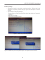
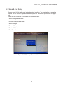
1
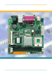
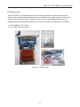
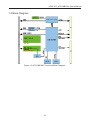
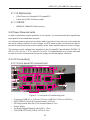
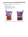
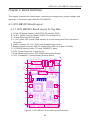
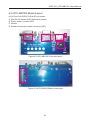
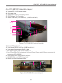
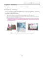
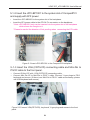
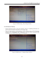
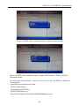
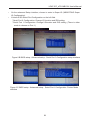
User's Manual
CompactPCI CPU System Card
LEAP IPC_cPCI-MB1001 User's Manual
Revision History
Release Date
2013/5/28
1.00
Revision
2
Descriptions
First Version
LEAP IPC_cPCI-MB1001 User's Manual
Copyright
The documentation and the software included with this product are copyrighted
by LEAP Electronic Co., Ltd. LEAP Electronic Co., Ltd. reserves the right to make
improvements in the products described in this manual at any time without notice. No
part of this manual may be reproduced, copied, translated or transmitted in any form
or by any means without the prior written permission of LEAP Electronic Co., Ltd.
Information provided in this manual is intended to be accurate and reliable. How-ever,
LEAP Electronic Co., Ltd. assumes no responsibility for its use, nor for any infringements of the rights of third parties, which may result from its use.
Acknowledgements
Intel and Pentium are trademark of Intel.
Microsoft Windows and MS-DOS are registered trademarks of Microsoft Corp.
All other product names or trademarks are properties of their respective owners.
Technical Support and Assistance
1. Visit the Leap website at http://www.leaptronix.com where you can find
the latest information about the product.
2. Contact your distributor, sales representative, or LEAP's customer service
center for technical support if you need additional assistance. Please have the
following information ready before you call:
– Product name and serial number.
– Description of your peripheral attachments.
– Description of your software (operating system, version, application software,
etc.)
– A complete description of the problem.
– The exact wording of any error messages.
3
LEAP IPC_cPCI-MB1001 User's Manual
Warnings, Cautions and Notes
Warning!
Warnings indicate conditions, which if not observed, can cause personal injury!
Caution!
Cautions are included to help you avoid damaging hardware or losing data. e.g.
There is a danger of a new battery exploding if it is incorrectly installed.
Do not attempt to recharge, force open, or heat the battery. Replace the
battery only with the same or equivalent type recommended by the manufacturer. Discard used batteries according to the manufacturer's instructions.
Note!
Notes provide optional additional information.
Document Feedback
To assist us in making improvements to this manual, we would welcome comments and
constructive criticism. Please send all such - in writing to: [email protected]
Or call the Free service tel: 0800-008-996
4
LEAP IPC_cPCI-MB1001 User's Manual
Packing List
The cPCI-MB1001 is packaged with the following components. Before setting up the
system, check that the items listed below are included and in good condition. If any item
does not accord with the table, whatever it be missing or damaged,please retain the
shipping carton and packing material and contact the dealer for inspection immediately.
1 x cPCI-MB1001 CPU Card
1 x 2.5” HDD accessory pack
Figure 0.1 Packing List
5
Content
Revision History .........................................................................2
Copyright ...................................................................................3
Acknowledgments ......................................................................3
Technical Support and Assistance ..............................................3
Warnings,Cautions and Notes ....................................................4
Document Feedback ..................................................................4
Packing List ................................................................................5
Chapter 1 Introduction .............................................................10
1-1 Overview .......................................................................10
1-2 Features ........................................................................10
1-3 Block Diagram ...............................................................11
Chapter 2 Specifications .........................................................12
2-1 H/W Specifications ........................................................12
2-2 Power Requirements .....................................................13
2-3 I/O Connectivity .............................................................13
Chapter 3 Functional Description ............................................15
3-1 Processor ......................................................................15
3-2 Chipset ..........................................................................16
3-3 Super I/O Controller .......................................................16
3-4 Battery ...........................................................................16
3-5 Power On/Off Push Button .............................................17
3-6 Jumper Setting for clear RTC data (JP1) .......................17
Chapter 4 Board Interfaces .....................................................18
4-1 cPCI-MB1001 Board Layout ..........................................18
4-2 cPCI-AB1001 Board Layout ...........................................20
4-3 cPCI-AB1001 Board Layout ...........................................21
4-4 cPCI-MB1001 Assembly Layout ....................................22
Chapter 5 Installation ..............................................................23
5-1 H/W Installation .............................................................23
5-2 Drivers Installation .........................................................25
Content
Chapter 6 BIOS Setup .............................................................26
6-1 Entering Setup ...............................................................26
6-2 Main Setup ....................................................................26
6-3 Advanced Setup ............................................................27
6-4 Chipset Setup ................................................................33
6-5 Boot Setup .....................................................................34
6-6 Security Setup ...............................................................35
6-7 Save & Exit Setup ..........................................................36
Appendix
List of Figures
Figure 0.1 Packing List ...............................................................5
Figure 1.1 cPCI-MB1001 outlook .............................................10
Figure 1.2 cPCI-MB1001 Functional Block Diagram ................11
Figure 2.1 Front panel I/O connecting ports .............................13
Figure 2.2 cPCI-MB1001cPCI-MB1001 front and back side build
in models/BUS/Connecting port ..............................14
Figure 3.1 Power On/Off Push Button on the front boar ............17
Figure 3.2 Jumper Setting for clear RTC data (JP1) .................17
Figure 4.1 cPCI-MB1001 Front side Layout Description ..........18
Figure 4.2 cPCI-MB1001 Backside Layout Description ............19
Figure 4.3 cPCI-AB1001 Front side Layout Description ..........20
Figure 4.4 cPCI-AB1001 Backside Layout Description ............20
Figure 4.5 cPCI-AB1002 Front side Layout Description ...........21
Figure 4.6 cPCI-AB1002 Bottom side layout ............................21
Figure 4.7 cPCI-MB1001 front and rear side ............................22
Figure 4.8 cPCI-MB1001 rear side layout .................................22
Figure 5.1 cPCI-MB1001 Install SATA disk and fixing frame ….23
Figure 5.2 Insert cPCI-BP1001 to the CompactPCI backplane
.................................................................................24
Figure 5.3 Connect VGA(CRT/LCD), key board, Y type plugs and
mouse to the front panel ..........................................24
Figure 6.1 Enter BIOS setup Interface ......................................26
Figure 6.2 BIOS setup – Main Setting Window .........................27
Figure 6.3 BIOS setup - Advance Setup Interface ...................27
Figure 6.4 BIOS setup- Advanced setup-CPU configuration set
up interface ..............................................................28
Figure 6.5 BIOS set up -Advanced setup -Choose mode
interface ..................................................................29
Figure 6.6 BIOS setup- Advanced setup-Legacy IDE ChannelsSATA or PATA on Compatible Mode .........................29
Figure 6.7 BIOS setup – Advanced setup – Intel IGD SWSCI
OpRegion Configuration -DVMT Mode Select in
terface….................................................................30
Figure 6.8 BIOS setup-Advanced setup -Intel IGD SWSCI
OpRegion ................................................................30
Figure 6.9 BIOS setup -Advanced setup - USB Status setting
interface ..................................................................31
Figure 6.A BIOS setup- Advanced setup - USB ConfigurationUSB FLASH DRIVE PMAP ......................................31
Figure 6.B BIOS setup- Advanced setup - Serial Port 0
Configuration setup interface...................................32
Figure 6.C BIOS setup-Advanced setup - Serial Port 1
Configuration Device Mode interface......................32
Figure 6.D BIOS setup - Chipset setup-Host Bridge SetupOnChip VGA Configuration interface .......................33
Figure 6.E BIOS setup- Chipset setup- South Bridge setupUSB Port numbers and function setting interface ...33
Figure 6.F BIOS setup- Boot setup interface …........................34
Figure 6.G BIOS setup-Boot setup-Boot Option- Boot Option
Priorities interface ....................................................34
Figure 6.H BIOS setup- Security setup interface ......................35
Figure 6.I BIOS setup- Save and leave window ........................36
LEAP IPC_cPCI-MB1001 User's Manual
Chapter 1 Introduction
1-1 Overview
The cPCI-MB1001 is a 3U CompactPCI single board computer in triple-slot (12HP) width
form factor featuring the Intel Atom D525 processor with ICH8M I/O Controller Hub.
The cPCI-MB1001 provides one 204-pin SoDIMM socket, up to 2GB DDR3 memory, and
integrated graphics on the CPU and 2.5” SATA HDD connector. Front panel I/O includes
USB x2, GbE x1, VGA x1, and additional USB x8, RS-232 x2, PS/2 KB/MS x1.
The cPCI-MB1001 is ideally suited for transportation, factory automation, and other
industrial applications.
Figure 1.1 cPCI-MB1001 outlook
1-2 Feature
•
•
•
•
•
•
•
•
Support Dual-Core Intel Atom D525.
One 204-pin SoDIMM socket, support up to 2GB DDR3 RAM.
Support VGA , up to QXGA 2048x1536 RGB Display.
One 10/100/1000 Mbps (Gbe) Ethernet NIC for Realtek.
Ten USB 2.0 Ports.
One SATA direct connector for 2.5” HDD.
Two Serial Ports RS-232.
One PS/2 KB/Mouse port.
10
LEAP IPC_cPCI-MB1001 User's Manual
1-3 Block Diagram
Figure 1.2 cPCI-MB1001 Functional Block Diagram
11
LEAP IPC_cPCI-MB1001 User's Manual
Chapter 2 Specifications
2-1 H/W Specifications
2-1-1 Processor
• μFC-BGA dual-core Intel AtomTM Processor D525 1.8 GHz, 1MB L2 cache,
TDP 13W.
• Passive HeatSink.
2-1-2 Chipset
•
Intel ICH8M I/O Controller Hub (ICH).
2-1-3 Memory
• One 204-pin SoDIMM DDR3 socket.
• Up to 4GB.
2-1-4 Graphics
• Integrated in Intel Atom Processor.
• Up to QXGA 2048x1536@60Hz 32bit for analog monitor.
2-1-5 Ethernet
• One PCIe x1 RTL8111 GbE controller.
2-1-6 Serial Ports
• Up to two 16c550 compatible RS-232.
• Two DB9 ports on front panel.
2-1-7 Storage
• 2.5” SATA HDD connector onboard.
2-1-8 USB
• Ten USB2.0 ports.
2-1-9 KB/MS
• One Mini-DIN KB/MS connector.
12
LEAP IPC_cPCI-MB1001 User's Manual
2-1-10 Mechanical
• 100x160mm for Standard 3U CompactPCI.
• Triple-slot (12HP, 60.96mm) width.
2-1-11 BIOS
• AMIBIOS 16Mbit SPI flash memory.
2-2 Power Requirements
In order to guarantee stable operation of the system, it is recommended that significantly
more power be provided than required.
An industrial power supply unit should be able to provide at least twice as much power as
the entire system requires of each voltage. An ATX power supply unit should be able to
provide at least three times as much power as the entire system requires of each voltage.
The tolerance of the voltage lines described in the CompactPCI specification (PICMG 2.0
R3.0) is +5%/-3% for 5, 3.3 V and ±5% for ±12V. This specification is for power delivered
to each slot and it includes both the power supply and the backplane tolerance.
2-3 I/O Connectivity
2-3-1 Front panel I/O connect port
USB 2.0 Port 2
USB 2.0 Port 3,4,5 ...........,10
USB 2.0 Port 1
VGA-RGB Port
GigaPort
LED Indicator
(Red)Disk
(Green)Power
Power Switch
Com Port 2
(RS-232)
Com Port 1
(RS-232)
P/S-2 Keyboard/Mouse Port
Figure 2.1 Front panel I/O connecting ports
•
•
•
•
•
•
Front panel USB 2.0 x 10 Ports. (2 Ports on MB1001, 8 Port on AB1001)
UART (RS232) D-Sub 9 Pin(male header) x2 Ports.
PS/2 key boards/ Mini-Din 6 Pin female headerx1 Port.
Power Switch.
On Board Gigabit Ethernet with RJ45 x 1 Port.
VGA-RGB (CRT/LCD) D-Sub 15 Pin x1 Port.
13
LEAP IPC_cPCI-MB1001 User's Manual
2-3-2 Build in model/BUS/ device connecting port
•
•
•
•
•
•
DDR3 So-Dimm Socket.
SATA disk connector ( 5 + 7 Pin).
Compact-PCI System Bus J1 connector.
Compact-PCI System Bus J2 connector.
CPU heat dissipation fan connector (3 Pin) x1.
CMOS battery holder (CR2032) x1.
DDR3 SoDimm Port
CPU heat dissipation fan
3V Battery Holder
SATA disk port(2.5'' disk)
CompactPCI
Bus J1
CompactPCI Bus
J2 connector
Figure 2.2 cPCI-MB1001 front and back side build in module/BUS/Connecting port
14
LEAP IPC_cPCI-MB1001 User's Manual
Chapter 3 Functional Description
The following sections describe the cPCI-MB1001 features and functions.
3-1 Processor
The cPCI-MB1001 supports the Intel AtomTM Processor D500 Series processors built
on 45-nm Hi-K process technology.
The following list provides some of the key features of this processor (D525):
• One die, primary 32-kB instructions cache and 24-kB write-back data cache.
• Intel Hyper-Threading Technology (2 threads per core).
• On die 2x512-kB, 8-way L2 cache.
• Support IA 32-bit and Intel 64 architecture.
• Intel SSE2 and SSE3 and SSSE3 support.
• Micro-FCBGA8 packaging technologies.
• Thermal management support via Intel Thermal Monitor 1 (TM1).
The following list outlines the key features of system memory support:
• One channel DDR3 memory.
• Memory DDR3 data transfer rates of 800 MT/s.
• Non-ECC, unbuffered DDR3.
• I/O Voltage of 1.5V for DDR3.
• 1GB, 2GB and 4GB DDR3 DRAM technologies supported.
The following list outlines the key graphics features:
• The integrated graphics controller contains a refresh of the 3rd generation graphics
core.
• Intel Dynamic Video Memory Technology 4.0.
• Directx* 9 compliant Pixel Shader v2.0.
• 400-MHz render clock frequency.
• Analog RGB display output up to resolution up to 2048x1536 @ 60Hz.
15
LEAP IPC_cPCI-MB1001 User's Manual
3-2 Chipset
The cPCI-MB1001 supports the Intel ICH8M I/O Controller Hub, and provides extensive
I/O support. Functions and capabilities include:
• Provides 6 PCI Expressx1 ports, supporting the PCI Express Base Specification,
Revision 1.1. Each Root Port supports 2.5GB/s bandwidth in each direction. The
cPCI-MB1001 utilizes one PCI Express x1 ports for one Gigabit Ethernet controllers;
routes one PCI Express x4 port to the J2 connector for expansion capability.
• Enhanced DMA controller, interrupt controller, and timer functions
• Integrated Serial ATA host controller with independent DMA operation on three ports .
• System Management Bus (SMBus) Specification, Version 2.0 with additional support
for I2C devices .
• Supports Intel Matrix Storage Technology.
• PCI Local Bus Specification, Revision 2.3 support for 33MHz PCI operations .
3-3 Super I/O Controller
The Winbond W83627DHG-P Super I/O is on a Low Pin Count interface supporting
PS/2 keyboard/mouse; two 16C550-compatible serial ports; hardware monitor function to
monitor CPU voltage, CPU temperature, power supply voltages and system temperature;
and Watchdog Timer with time resolution from minimum 1 second or minute to maximum
65635 seconds or minutes on the cPCI-MB1001.
3-4 Battery
The cPCI-MB1001 is provided with a 3.0V “coin cell” lithium battery for the Real Time
Clock (RTC). The battery socket is equipped on the board. The lithium battery must be
replaced with an identical battery or a battery type recommended by the manufacturer.
16
LEAP IPC_cPCI-MB1001 User's Manual
3-5 Power On/Off Push Button
There is power on/ off push button on cPCI-MB1001(On the front panel, at SW1 position
on the cPCI-AB1002). You can use ballpoint pen or small screwdriver to press it for power
on or off.
Front panel hole:
Power on/off
push button
Figure 3.1 Power On/Off Push Button on the front boar
3-6 Jumper Setting for clear RTC data (JP1)
The cPCI-MB1001 contains a jumper that can clear RTC data. Normally this jumper
should be set with pins 1-2 closed. If you want to reset the RTC data, set J1 to 2-3 closed
for just a few seconds, and then move the jumper back to 1-2 closed. This procedure will
clear the RTC to its default setting.
Normal Operate: JP1 1-2 Pin short circuit
RTC Reset: JP1 2-3 Pin short circuit
2
3
1
2
Figure 3.2 Jumper Setting for clear RTC data (JP1)
17
LEAP IPC_cPCI-MB1001 User's Manual
Chapter 4 Board Interfaces
This chapter illustrates the board layout, connector pin assignments, jumper settings, and
assemble to familiarize users with the cPCI-MB1001.
4-1 cPCI-MB1001 Board Layout
4-1-1 cPCI-MB1001 Board Layout for Top Side
A. D-Sub15P female header (VGA(CRT/LCD monitor) RGB).
B-1 & B-2. USB A-Type pin header (USB 2.0 Port0 and Port1).
C. Gigabit Ethernet with RJ45 port.
D. 1 red 1 green LED module (Red indicator is for disk saving and Green indicator is
for power)
E. Wafer connector 3P (+12V CPU heat dissipation fan control)
F. Board to board connector 40P (To extend other USB 2.0 x8 port of ICH8M).
G. 3V CR2032 battery holder (To keep CMOS/RTC data).
H. CPU, Screw fixing hole of heat sink x4.
I. 3P pin header and Jumper (RTC/CMOS data erase (Reset)).
J1 & J2. CompactPCI female header (System Board).
C
A
D
B-1
B-2
F
E
G
I
H
H
J1
J2
Figure 4.1 cPCI-MB1001 Front side Layout Description
18
LEAP IPC_cPCI-MB1001 User's Manual
4-1-2 cPCI-MB1001 Board Layout: Bottom Side
L. Board to board connector 40P (Connect to UART (RS-232) Com Port x2 and
System Reset switch).
M. DDR3 SoDimm socket x1.
N. BIOS SPI Flash programming interface (2x4P pin header).
O. SATA disk port ( 2.5” SATA 2.0 disk).
L
M
N
M
Figure 4.2 cPCI-MB1001 Bottom Side Layout
19
LEAP IPC_cPCI-MB1001 User's Manual
4-2 cPCI-AB1001 Board Layout
#2,#3,...#9. USB2,0 A-Type pin header.
A. Board to board connecting female header (40P).
#9
#2
#3
Figure 4.3 cPCI-AB1001 Front side layout
A
Figure 4.4 cPCI-AB1001 Bottom Side Layout
20
LEAP IPC_cPCI-MB1001 User's Manual
4-3 cPCI-AB1002 Board Layout
#1,#2 Com Port RS232 D-Sub 9P pin header.
A. Mini-Din 6P female (PS/2 keyboard/ mouse).
B. Power switch: Location SW1.
C. Buzzer.
D. Board to board pin header connector (40P).
B
#1
#2
A
C
Figure 4.5 cPCI-AB1002 Front side layout
D
Figure 4.6 cPCI-AB1002 Bottom side layout
21
LEAP IPC_cPCI-MB1001 User's Manual
4-4 cPCI-MB1001 Assembly Layout
A. CompactPCI J1/J2 female header.
B. CPU Heat Sink.
C. CMOS/RTC battery and battery holder.
D. CPU Radiator Fan Controller.
E. USB 2.0 x8 Ports ( cPCI-AB1001) , (USB Port #2~#9.)
E
E
(#2~#9)
B
A
H
#0
#1
K
K
D
C
J
F
Figure 4.7 cPCI-MB1001 front and rear side
F. CompactPCI push rod.
G. Front panel USB 2.0 x2 Port. (USB Port #0~#1.)
H. Front plane Ethernet with RJ45 x1 port.
I. Front panel (D-Sub 15P female header) x1.
J. Com1/Com2/Mini-Din for keyboad & mouse/ Reset Power switch/ Buzzer connector for
connecting cPCI-AB1002.
K. Front panel Com1/Com2 RS-232 x2 port.
L. 2.5” SATA Disk and SATA fixing frame.
M. DDR3 So-Dimm module and port.
M
A
J
L
Figure 4.8 cPCI-MB1001 rear side layout
22
LEAP IPC_cPCI-MB1001 User's Manual
Chapter 5 Installation
This chapter describes the hardware and software installation.
5-1 Hardware Installation
5-1-1 Install the 2.5 inch SATA disk on the fixing frame.: (Use the
accessory SATA screws)
• Take out the screws and the SATA fixing frame and lock it as figure 5-1.
• Turn the board upside down and insert the SATA disk and locked fixing frame to
the board then lock the fixing screws.
* Lock the SATA disk (2.5 inch) and fixing frame with screws. (Note: It is tionality.)
* Insert the SATA disk (2.5 inch) and fixing frame to the SATA connector, then lock
the 4 fixing screws.
A.
B.
D.
Figure 5.1 cPCI-MB1001 Install SATA disk and fixing frame
23
LEAP IPC_cPCI-MB1001 User's Manual
5-1-2 Insert the cPCI-BP1001 to the system slot of CompactPCI
and supply with ATX power:
• Insert the cPCI-MB1001 to the system slot of the backplane.
• Insert the ATX power cable to the ATX 24 Pin connector on the backplane.
* Note: cPCI-MB1001 only can be inserted into the system slot of the backplane
which shown the trangle on it.
* Please be careful the direction of fool proofing when connecting the ATX cable.
Figure 5.2 Insert cPCI-BP1001 to the CompactPCI backplane
5-1-3 Insert the VGA (CRT/LCD) connecting cable and Mini-Din to
PS/2Y cable to the front panel.
• Connect D-Sub 15P with VGA (CRT/LCD) connecting cable.
• Connect Mini-Din 6P to Mini-Din to PS/2 Y cable. Connect Y type plugs to PS/2
keyboard and mouse.( If there is no Mini-Din to PS/2 Y cable as accessory, please
use USB keyboard and mouse.)
Figure 5.3 Connect VGA(CRT/LCD), key board, Y type plugs and mouse to the front
panel.
24
LEAP IPC_cPCI-MB1001 User's Manual
5-2 Drivers Installation
The cPCI-MB1001 drivers are available from the LEAP All-In-One CD at X:\cPCIMB1001\, or from the LEAP website (http://www.leaptronix.com). This section
describes the driver installation procedures for Windows XP.
5-2-1 Install the Windows operating system before installing any
driver. Most standard I/O device drivers are installed during
Windows installation.
5-2-2 Running the Installer for the chipset driver.
5-2-3 Running the Installer for the VGA driver/Uitilitys.
5-5-4 Running the Installer for the Ethernet controller driver.
We recommend using the drivers provided on the LEAP All-in-One CD or downloaded
from the LEAP website to ensure compatibility.
25
LEAP IPC_cPCI-MB1001 User's Manual
Chapter 6 BIOS Setup
The following chapter describes basic navigation for the AMI Aptio BIOS setup utility.
6-1 Entering Setup
• Turn on PC power and click <DEL> or <F2> to enter Main Setup of BIOS. Besides,
<F7> is for entering to the BBS POPup Menu.
Figure 6.1 Enter BIOS Setup Interface
6-2 Main Setup
• Main Setup interface is the first interface to enter. Please operate the cursor by
following the description on the buttom right window. (To change direction, change
line or page, <TAB>, <Enter>, change the value <+/->). There is a description of
these selections.
• It shows the BIOS version and supplier information on the left side of the main setting
window.
• System Time: Use arrow key and <TAB> to set the System Time to HH:MM:SS
format.
26
LEAP IPC_cPCI-MB1001 User's Manual
Figure 6.2 BIOS setting - Main Setting Window
6-3 Advanced Setup
• Choose Advanced mark to enter the interface. There is a operating description on
buttom right and selection description on the upper right.
• There are few hardware system settings on this interface, such as PCI Subsystem
Settings, CPU Configuration, IDE Configuration, Intel IGD SWSCI OpRegion,USB
Configuration and W83627DHG Super IO Configuration.
Figure 6.3 BIOS set up - Advance Setup Interface
27
LEAP IPC_cPCI-MB1001 User's Manual
• Choose the CPU Configuration and enter it on the Advanced Setup Window. The
left side window shows the Processor Type, Processor Speed, System Bus Speed
information.
* Hyper-Threading: Enabled/Disabled
* Core-Multi Processing: Enabled/Disabled
* Execute Disable Bit: Enabled/Disabled
Figure 6.4 BIOS setup - Advanced setup-CPU configuration set up interface
• Choose to enter IDE Configuration on the advanced interface. It shows the disk type
and capacity of SATA Port on the left side.
* ATA or IDE Configuration:
Disabled/Compatible/Enhanced
* SATA(Configure SATA As):
(IDE/AHCI) In Enhanced mode
* Legecy IDE Channels:
(SATA Only/SATA Pri, PATA Sec/PATA Only)
28
LEAP IPC_cPCI-MB1001 User's Manual
Figure 6.5 BIOS setup - Advanced setup -Choose mode interface
Figure 6.6 BIOS setup- Advanced setup - Legacy IDE Channels - SATA or PATA on
Compatible Mode
• On Advanced Setting Mode, choose to enter the Intel IGD SWSCI OpRegion
Configuration:
• It shows below functions on left field:
* (DVMT Mode Select):
(Fixed Mode/DVMT Mode)
* (DVMT/FIXED Memory):
Select DVMT Mode/ Fixed Mode(128MB/256MB/Maximum)
29
LEAP IPC_cPCI-MB1001 User's Manual
Figure 6.7 BIOS setup - Advanced setup - Intel IGD SWSCI OpRegion
Configuration - DVMT Mode Select interface
Figure 6.8 BIOS setup - Advanced setup - Intel IGD SWSCI OpRegion
Configuration - DVMT/FIXED Memory interface
30
LEAP IPC_cPCI-MB1001 User's Manual
• In the Advanced setupmode, choose to enter the USB Configuration.
• There are USB Port types and numbers in the left field.
* Legacy USB Support: Enable/Disable/Auto
* EHCI Hand-off: Disable/Enable
* USB hardware delays): simple description
* Mass Storage Devices:
Insert the USB storage device before starting up the machine. It can be set up as
(Auto/Floppy/Forced FDD/Hard Disk/CD-ROM) after Boot detecting the device.
Figure 6.9 BIOS setup - Advanced setup - USB Status setting interface
Figure 6 .A BIOS setup - Advanced setup - USB Configuration - USB FLASH DRIVE PMAP
31
LEAP IPC_cPCI-MB1001 User's Manual
• On the advanced Setup interface, choose to enter to Super IO (W83627DHG Super
IO Configuration).
• It lists the SIO Serial Port Configuration on the left field.
* Serial Port 0 Configuration: Change I/O location and IRQ setting.
* Serial Port 1 Configuration: ChangeI /Olocation and IRQ setting. (There is other
mode to choose on Port 1.)
Figure 6.B BIOS setup - Advanced setup - Serial Port 0 Configuration setup interface
Figure 6.C BIOS setup - Advanced setup - Serial Port 1 Configuration Device Mode
interface
32
LEAP IPC_cPCI-MB1001 User's Manual
6-4 Chipset Setup
• Choose Chipset mark to enter the Chipset Setup. Bottom right is the description of
operating buttons and upper right is the description of selection function.
• There are some hardware system settings on the Advanced setting mode:
Host Bridge /South Bridge.
* Host Bridge includes OnChip VGA Configuration (1MB/8MB).and Memory
information ,Memory Frequency,Size and Dimm socket position information.
* South Bridge includes USB Ports and numbers.
USB 2.0 (EHCI) support set up
PCI-Express x1 Port (High Priority Set up).
Figure 6.D BIOS setup - Chipset setup-Host Bridge setup - OnChip VGA
Configuration interface
Figure 6.E BIOS setup - Chipset setup- South Bridge setup - USB Port numbers and
function setting interface
33
LEAP IPC_cPCI-MB1001 User's Manual
6-5 Boot Setup
• Choose Boot mark to enter start up setting interface. Bottom right is the
description of operating buttons and upper right is the description of selection
function.
• Few functions on the setup interface:
* Bootup NumLock State/Quiet Boot(Only shows Logo without self examine)/
Fast Boot.
* Boot Option Priorities:
* (BBS) Hard Drive BBS Priorities.
Figure 6.F BIOS setup - Boot setup interface
Figure 6.G BIOS setup - Boot setup-Boot Option - Boot Option Priorities interface
34
LEAP IPC_cPCI-MB1001 User's Manual
6-6 Security Setup
• Choose Security mark to enter to the security setup mode. Bottom right is the
description of operating buttons and upper right is the description of selection
function.
• Functions on the security mode:
* Administrator Password
* User Password
Figure 6.H BIOS setup - Security setup interface
35
LEAP IPC_cPCI-MB1001 User's Manual
6-7 Save & Exit Setup
• Choose Save & Exit option and enter the setup interface. The description of operating
buttons are on bottom right and the description of selection options are on upper
right.
• There are few functions on the save and leave interface:
* Save Changes and Reset
* Discard Changes and Reset
* Save Changes
* Discard Changes
* Restore Defaults
* Boot Override
Figure 6.I BIOS setup - Save and leave window
36
Document No.: 140227-V1.0
80500822110001
WEB: www.leap.com.tw
www.leap.net.cn
E-MAIL: [email protected]
LEAP Headquarters
Shanghai Office (China)
TEL: +886-2-2999-1860 #15
FAX: +886-2-2999-9873
6F-4, No.4, Ln.609, Sec.5, Chongxin Rd.,
Sanchong Dist., New Taipei City 24159,
Taiwan, ROC
TEL: +86-21-5777-1796
FAX: +86-21-5777-1796 #838
Songjiang District, Shanghai Xin Brick
Road, Room 301, 518, No. 24
LEAPTRONIX Headquarters
Beijing Office (China)
TEL: +886-2-2999-3837
FAX: +886-2-2999-7710
9F-4, No.18, Ln.609, Sec.5, Chongxin Rd.,
Sanchong Dist., New Taipei City 24159,
Taiwan, ROC
TEL: +010-6265-2592
FAX: +010-6265-5303
No. 615, Apartment, No. 33 Suzhou St.,
Haidian District, Beijing
Dongguan Office (China)
TEL: +0769-8534-9978
FAX: +0769-8534-9686
12F, Hua’an Shangzhu Building, Changqing
St., Chang'an Town, Dongguan


![User's Manual AH-480 Series [Machine / Software]](http://vs1.manualzilla.com/store/data/006867875_1-b2cd01726e15f409a063f19433f9385d-150x150.png)

![English Manual AH-160C [Hardware & Software]](http://vs1.manualzilla.com/store/data/005931679_1-0c77ed47c849260a36e03decc8d56d96-150x150.png)