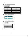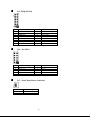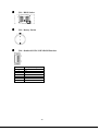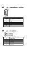
1
WTP-8B66 Series User’s Manual P/N: 205G00WTP8B660, Version V1.0 Copyright 2015, ALL RIGHTS RESERVED. All other brand names are registered trademarks of their respective owner Copyright Notice Copyright © 2015 All Rights Reserved. Printed in Taiwan. The information contained in this document is subject to change without any notices. Acknowledgments Greeting & Setup Thank you for purchasing the WTP-8B66 Panel PC. We wish that this unit will be durable and reliable in providing your needs. Please follow the instructions below to ensure the unit continues to have high performance Unpacking After opening the carton, there will be a unit with an accessory box. Examine the contents to see if there are damages to the unit and if all accessories are present. Setting up Please read this manual carefully and remember to keep this manual for future reference. Safety Instructions & Cleaning The unit has undergone various tests in order to comply with safety standards. Inappropriate use may be dangerous. Please remember to follow the instructions below to insure your safety during the installation and operating process. Transporting & Placement of unit 1. When moving the unit on a cart; be very cautious. Quick stops, excessive forces and uneven surfaces may cause the cart to overturn thus risking the unit to fall to the ground. 2. If the Monitor display unit does fall to the ground, immediately turn the power off and disconnect cords. Then contact a service technician for repairs. Continual use of the unit may result cause a fire or electric shock. Also, do not repair the unit on your own. 3. Having two or more people transporting the display unit is recommended. In addition, when installing the open frame by suspending it also requires two or more people. 4. Before suspending the unit, make sure the material used for suspension is sturdy and stable. If not properly suspended, the display unit may fall and cause serious injury to people standing nearby as well as to the unit itself. 5. If you wish to mount the display unit, remember to use only the mounting hardware recommended by the manufacturer. Electrical and Power Source Related 1. This Monitor display unit must operate on a power source as shown on the specification label. If you are not sure what type of power supply used in the area, consult your dealer or local power supplier. 2. The power cords must not be damaged. Applied pressure, added heat, and tugging may damage the power cord. 3. The power cord must be routed properly when setup takes place. We advise that this aspect measure is to prevent people from stepping on the cords or while the unit is suspended to prevent flying objects from getting tangled with the unit. 4. Do not overload the AC outlets or extension cords. Electrical shocks or fires may occur from overloading. 5. Do not touch the power source during a thunderstorm. 6. If your hands are wet, do not touch the plug. 7. Use your thumb and index finger, grip firmly on the power cord to disconnect from the electrical socket. By pulling the power cord, may result in damaging it. 8. If the unit is not going to be in use for an extended period of time, remember to disconnect the unit. 9. Connect the unit to a power source with the same numerical value as spec. label shown. Please use only the power cord provided by the dealer to ensure safety and EMC compliance. Various Factors of Environment 1. Do not insert objects into the openings. 2. Do not have liquids seep into the internal areas of the Monitor display unit. 3. Having liquids seep in or inserting objects into the unit may result in electric shocks from taking and/or short circuiting the internal parts. 4. Do not place the Monitor display unit in the presence of high moisture areas. 5. Do not install the Monitor display unit in a wet environment. 6. Do not place near unit near heat generating sources. 7. Do not place the unit in a location where it will come in contact with fumes or steam. 8. Remember to keep the Monitor display unit away from the presence of dust. 9. If water has flow in or seep in, immediately disconnect the open frame unit. Then contact a service technician for repairs. Ventilation Spacing 1. Do not cover or block the openings on the top and back sides of the display unit. Inadequate ventilation may cause overheating thus reducing the lifespan of the unit. 2. Unless proper ventilation is present, do not place unit in an enclosed area; such as a built-in shelf. Keep a minimum distance of 10 cm between the display unit and wall. Cleaning the unit 1. Remember to turn off the power source and to unplug the cord from the outlet before cleaning the unit. 2. Carefully dismount the unit or bring the unit down from suspension to clean. 3. Use only a dry soft cloth or clean room wiper when cleaning the LCD panel or touch screen surface. Use a soft cloth moistened with mild detergent to clean the display housing. 4. Remember to avoid having liquids seep into the internal components. Servicing, Repairing, Maintenance & Safety Checks 1. If the unit is not functioning properly, observe the performance level of the display closely to determine what type of servicing is needed. 2. Do not attempt to repair the Monitor display unit on your own. Disassembling the cover exposes users’ to high voltages and other dangerous conditions. Notify and request a qualified service technician for servicing the unit. 3. If any of the following situations occur turn the power source off and unplug the unit. Then contact a qualified service technician i. A liquid was spilled on the unit or objects have fallen into the ii. unit. The unit is soaked with liquids. iii. The unit is dropped or damaged. iv. If smoke or strange odor is flowing out of the open frame unit. 4. v. If the power cord or plug is damaged. vi. When the functions of the unit are dysfunctional. When part replacement is needed. Make sure service technician uses replacement parts specified by the manufacturer, or those with the same characteristics and performance as the original parts. If unauthorized parts are used it may result in starting a fire, electrical shock and/or other dangers. Battery Installation Follow below instructions and notice the caution for replacing and disposing of the RTC Lithium battery CR2032 for safety consideration. CAUTION: There is danger of explosion, if battery is incorrectly replaced. Replace only with the same or equivalent type recommended by the manufacturer. Dispose of used batteries according to the manufacturer’s instruction. The specification is subject to change without notice. Version Change History Date Version Description Remark 2014/12/29 V1.0 First release Ivy How to Use This Manual .................................................... 1 System Overview ..................................................... 2 System View ....................................................................... 7 Setting up the System.......................................................... 9 Installing System Software ................................................. 9 Installing the Drivers......................................................... 10 Appendix .............................................................. 11 A. Jumper settings and Connectors .................... 11 How to Use This Manual This manual is written for the system integrator, PC technician and knowledgeable PC end user. It describes how to configure your WTP-8B66 Panel PC to meet various operating requirements. The user’s manual is divided into three chapters, with each chapter addressing a basic concept and operation of the server board. Chapter 1: System Overview - presents what you have inside the box and gives you an overview of the product specifications and basic system architecture for the WTP-8B66 Panel PC. Chapter 2: System Installation - describes how to set up the system. Chapter 3: BIOS Setup Information - specifies the meaning of each setup parameter, how to get advanced BIOS performance and update to a new BIOS. Additionally, the POST checkpoint list will give you a guide for troubleshooting. The contents of this manual are subject to change without prior notice. These changes will be incorporated in new editions of this manual. Touch Chemical Resistance 1 System Overview WTP-8B66- 15 System CPU Intel® Celeron® J1900 2.0 GHz quad-core processor 10W Graphic Intel® HD Graphics Audio Realtek ALC262 Audio Codec, 2+2 watts power amplifier LAN Intel I210-AT Gigabit Ethernet x 2 Memory Dual Channel, two DDR3 SODIMM socket support up to 8GB DDR3L-1333 Serial ATA SATA II controller (3.0Gb/sec) Port x 2 Serial port External RS232/RS422/RS485 x 1(BIOS , RS485 auto flow), RS232 x 1 Internal RS232 x 1 RS232 (Jumper 5V, 12V) x1 USB External USB 2.0 type a x 4 Internal Mini-PCIE x 2(default) or USB 2.0 pinhead x 2(option) Touch x 1 Pin head X 2 WDT Generates system reset; 256 segments, 0, 1, 2…25 設定 BIOS Brand: AMI Flash ROM size: 64MB Support RTC wakeup /Wake on LAN /Power on after power failure/PnP/AC PI/RTC **com port have to be disabled if PXE enable. It is a limitation Press F11 to Quick boot menu. Select First LAN port for PXE boot. Display Brand Model Resolution (pixel) Active Area (mm) Tianma TM150TDS50 1024x768 XGA 304.128 (W) x 2 228.096 (V) 326.5 (H) ×253.5 (V) ×11.8 0.297 TN 16.7M 160/160 400 600:1 8 Outline Dimensions (mm) Pixel Pitch (mm) Mode Number of Colors View Angle (H/V) Brightness (cd/m2) Contrast Ratio Response Time (ms) (at 25°C) Backlight Weight (g) life time<Hrs> Touch Screen LED 1000 50000 ELO Model name Type Glove Stylus Interface Light Transmission Hardness Glass thickness Linearity Active area Resolution Lifetime Storage 2.5” SATA E249624 5 wire RES Any type glove No Limitation, can use any stylus USB 80±5% 4H 2.4mm X 1.5%, Y 1.5% ≦ ≦ 308.11x232.09mm 4096x4096 35 million activations drive bay x 1 Expansion slots Mini-PCIe x2 External water/dust resistant I/O (rear side) USB 1 x M12 8pin for USB 1/2 1 x M12 8pin for USB 3/4 COM 1 x M12 8pin for COM 1/RS-232/422/485 (Default RS-232) 1 x M12 8pin for COM 2/RS-232 RS-232: TxD, RxD, RTS, CTS, DTR, DSR, DCD, GND LAN Power 1 x M12 8pin for LAN 1 1 x M12 5pin DC power connector Power Power Power Input Power Adapter Power consumption DC-In connector x 1 DC7V~32V AC 90 ~ 264V / 47 ~ 63 Hz / DC output 12V, IP67 Power ON/Off and reset buttons at rear side 67.5w(full loading) 2.3w (S3) Mechanical & Environmental Material construction SUS304 stainless steel enclosure, chassis type 3 Fanless cooling Water and dust protection Operation Temperature Storage Temperature Operation Relative Humidity Storage Relative Humidity Dimensions Net Weight Gross Weight Mounting Supported OS Win 7, Win 7 Pro, Win8.1 IP66 / NEMA4X (IEC60068-2-2, HDD, air flow cooling) 0~40 -20~60 10%~90%, non-condensing 10%~90%, non-condensing 395x309.5x58 12.4kg 8.4kg VESA (100x100 mmxmm), side mount (M6*2) ℃ ℃ Options 1. Wireless or WIFI and BT kit (2 ant) 2. Waterproof COM cable, cable length is 2 meters 3. Waterproof USB cable, cable length is 2 meters 4. Waterproof LAN cable, cable length is 2 meters 5. wall mount / table mount bracket (option) 6. SSD 7. Intel Core i7-3517U (option) turbo mode disable 8. 2 external LAN Customization (by DRF) 1. sunlight readable optical bonding 2. anti UV and 7H coating 3. full flat PCT touch screen IP69K 4. 1000 nit high brightness LCD 5. LCD Auto dimming 6. LCD Super dimming (low brightness) Packing list 7. WTP-8B66-15 8. DVD-Title for driver and manual 9. Power adapter 10. Power cord Regulatory FCC, CE (EMC), VCCI class B Shock/Vibration/Drop Shock Operating: Pulse shape Half-sine waveform Impact General acceleration 15g Pulse duration 11 ms Number of : : : Vibration Drop Operating: ISTA According to 5 ~ 500Hz , Project 2A Acceleration to determine a drop height in 1.0G Sweep time 15 the following chart. (test surface: concrete, minutes with packing)6 surfaces Number of Packag Drop Height cycle 1 cycle e-produ for each axis ct Vibration Weight axes X, Y and Z 21-40.9 32 in. : : : : 9 lb(0.813 m) 4 Shock/Vibration /Drop : (9.53-1 8.59kg) shocks 18 shocks (3 shock for each axis) Orientation X, Y and Z axes ± ± :± ± Configurations: 1. WTP-9ª66-15, Core i5-3317U CPU, 2G RAM, 320G HDD, 4 USB, 2 COM, 1 LAN WTP-8B66-19 System CPU FCBGA1023 3rd Generation Intel® Core i7/i5/i3/Celeron® processor (17W max.) Chipset Graphic Audio LAN Memory HM65 Intel® integrated HD Graphics 4000 None Marvell 88E8071 Giga LAN x 2 Two 1066/1333 MHz DDR3 SODIMM socket support dual Channel, non-ECC, up to 8GB I/O EC SATA SATA 3, 600 MB/s transfer rate x 2, 2nd SATA connector for SATA DOM propose. Serial port RS232,422,485 x 1 /RS232 x 5 USB External USB 2.0 x 4 (Type A) Internal USB 2.0x 5 WDT Generates system reset; 256 segments, 0, 1, 2…255 sec/min. BIOS Brand: AMI Flash ROM size: 32MB Support RTC wakeup /Wake on LAN /Power on after power failure/PnP/ACPI/RTC PS: com port have to be disabled if PXE enable. It is a limitation Display Brand Model Resolution (pixel) Active Area (mm) Number of Colors View Angle (H/V) Brightness (cd/m2) Contrast Ratio Response Time (ms) (at 25°C) Backlight Weight (g) life time<Hrs> AUO G190EG01 V1 SXGA 1280(x3) x 1024 376.32 (H) x 301.06(V) 16.7M 170 / 160 350 1000:1 5 LED 1670 50000 Touch Screen 5 ELO E000437 5 wire RES Any type glove No Limitation, can use any stylus USB 80±5% 4H 2.4mm X 1.5%, Y 1.5% 308.11x232.09mm 4096x4096 36 million activations Model name Type Glove Stylus Interface Light Transmission Hardness Glass thickness Linearity Active area Resolution Lifetime Storage 2.5” SATA ≦ ≦ drive bay x 1 Expansion slots Mini-PCIe x2 External water/dust resistant I/O (rear side) USB 1 x M12 8pin for USB 1/2 1 x M12 8pin for USB 3/4 COM 1 x M12 8pin for COM 1/RS-232 1 x M12 8pin for COM 2/RS-232 RS-232: TxD, RxD, RTS, CTS, DTR, DSR, DCD, GND LAN Power 1 x M12 8pin for LAN 1 1 x M12 5pin DC power connector Power Power DC-In connector x 1 Power Input DC7V~32V Power Adapter AC 90 ~ 264V / 47 ~ 63 Hz / DC output 12V, Power ON/Off and reset buttons at rear side Power consumption 67.5w(full loading) 2.3w (S3) Mechanical & Environmental Material construction SUS304 stainless steel enclosure , chassis type Fanless cooling Water and dust protection IP66 / NEMA4X (IEC60068-2-2, HDD, air flow cooling) Operation Temperature 0~40 Storage Temperature -20~60 Operation Relative Humidity 10%~90%, non-condensing Storage Relative Humidity 10%~90%, non-condensing Dimensions 458x386x64 Net Weight 11.5kg Gross Weight 15kg Mounting VESA (100x100 mmxmm) side mount (M6*2) Supported OS Win 7, Win 7 Pro, Win8.1 ℃ ℃ 6 Options 1. Wireless or Wireless and BT kit (2 ant) 2. Waterproof COM cable, cable length is 2 meters 3. Waterproof USB cable, cable length is 2 meters 4. Waterproof LAN cable, cable length is 2 meters 5. wall mount / table mount bracket (option) 6. SSD 7. Intel Core i7-3517U (option) turbo mode disable 8. 2 external LAN Customization (by DRF) 1. sunlight readable optical bonding 2. anti UV and 7H coating 3. full flat PCT touch screen IP69K 4. 1000 nit high brightness LCD 5. LCD Auto dimming 6. LCD Super dimming (low brightness) Packing list 7. WTP-8B66-19 8. DVD-Title for driver and manual 9. Power adapter 10. Power cord Regulatory FCC, CE (EMC), VCCI class B Shock Operating: Pulse shape Half-sine waveform Impact acceleration 15g Pulse duration 11 General ms Number of shocks 18 shocks (3 shock for each axis) Orientation X, Y and Z axes : : : : ± ± Shock/Vibration /Drop Vibration Drop Operating: ISTA According to 5 ~ 500Hz , Project 2A Acceleration to determine a drop Configurations: height in 1.0G 2. WTP-8B66-19, Sweep time 15 the following chart. Core i5-3317U (test surface: concrete, minutes CPU, 2G RAM, with packing)6 surfaces Number of 320G HDD, 4 Packag Drop Height cycle 1 cycle USB, 2 COM, 1 e-produ for each axis LAN ct Vibration Weight axes X, Y and Z 21-40.9 32 in. : : : : 9 lb(0.813 m) (9.53-1 8.59kg) System View WTP-8B66-15 Outline Drawing :± ± 7 8 WTP-8B66-19 Outline Drawing Setting up the System The following is a summary of the steps in setting up the system for use. CAUTION: Make sure that power to the system and each of the devices to be connected is switched OFF before plugging in the connectors. 1. Make any required external connections such as the keyboard, and mouse. 2. Plug the appropriate end of the power cord into the power connector of the system. Then plug the other end of the power cord to an electrical outlet. 3. Press the power switch of the system to turn on the system’s power. 4. If necessary, run the BIOS SETUP program to configure the system (see Chapter 3). 5. Install the software drivers if necessary. Installing System Software Recent releases of operating systems from major vendors include setup programs, which load automatically and guide you through hard disk preparation and operating system installation. The guidelines below will help you determine the steps necessary to install your operating system on the Panel PC hard drive. NOTE: Some distributors and system integrators may have already pre-installed system software prior to shipment of your Panel PC. Installing software requires an installed HDD. Software can be loaded in the WTP-8B66 Panel PC using any of below methods: Method 1: Use the Ethernet You can use the Ethernet port to download software from the net to the HDD that has been pre-installed in WTP-8B66 Panel PC Method 2: Use the COM Port 9 By connecting another PC to the WTP-8B66 Panel PC with an appropriate cable, you can use transmission software to transmit Operation System Software to the HDD that has been pre-installed in the WTP-8B66 Panel PC. Method 3: Use a External CD-ROM In order to boot up system from USB-CD/DVD drive, please connect USB-CD/DVD drive, turn on computer power, keep on pressing “F11” key, go into BIOS quick boot menu, select “USB-CD ROM”, WAIT FOR 20 SECONDS, then press enter, system OS will boot up from USB-CD/DVD drive directly Then you can use the external CD-ROM to transmit the software to the HDD that has been pre-installed in the WTP-8B66 Panel PC Installing the Drivers After installing your system software, you will be able to set up the LAN, VGA, Audio and USB functions. All drivers are stored in a CD disc, which can be found in your accessory pack. The various drivers and utilities in the disc have their own text files that help users install the drivers and understand their functions. Follow the sequence below to install the drivers: Step 1 – Install Intel® INF Driver Step 2 – Install Intel® VGA Driver Step 3 – Install Intel® LAN Driver Step 4 – Install Audio Driver Step 1 – Install Intel® INF Driver 1. Open fie of chipset 2. Click on the setup.exe 3. Follow the instructions that the window shows 4. The system will help you install the driver automatically 5. Reboot system Step 2 –Install Intel® VGA Driver 1. Open fie of VGA 2. Select the OS folder your system is 3. Click on the .exe file located in the OS folder 4. Follow the instructions that the window shows 5. The system will help you install the driver automatically 6. Reboot system Step 3 – Install Intel® LAN Driver 1. Open fie of LAN 2. Click on the setup.exe 3. Follow the instructions that the window shows 4. The system will help you install the driver automatically 5. Reboot system Step 4 – Install Audio Driver 1. Open fie of LAN 2. Click on the setup.exe 3. Follow the instructions that the window shows 4. The system will help you install the driver automatically 5. Reboot system 10 Appendix A. Jumper settings and Connectors JP5 – Backlight Type Selection Description Analog Inverter PWM Inverter Jumper Setting 1-2 (for 10”) 2-3(for 12’’/15”) 11 JP6 – Backlight control level Selection Description +3.3V +5V JP7 – Touch Panel Type Selection Description 3M type ELO type Jumper Setting 1-2 OPEN (default) Jumper Setting 1-2, 3-4 (default) 5-6,7-8 JP8 – LVDS Power Selection Description +3.3VS(for 10”/12”/15”) +5VS(for 17”/19”) Jumper Setting 5-6, 7-8 (default) 1-2, 3-4 12 JP9 – Sensor Selection Description No Panel Sensor No MB Sensor Reserved JP10 – CMOS Clear Description Normal Open CMOS Clear Jumper Setting 2-3(default) 1-2 JP12 – COM3 Power Selection Description +5VS +12VS Jumper Setting 1-2 (default) 2-3 JP11 – SATA / SATADOM Selection Description SATA SATA DOM Jumper Setting 1-2(default) 3-4 5-6 Jumper Setting 2-3(default) 1-2 JP13,J14 –Y cable* Support both DVI+VGA 13 Description JP13 No support (default) Open 1-2 Support *Support Wincomm Y cable only. JP14 Open 1-2 JP15 –Panel Resolution Selection JP15 jumper setting 1-2 0 0 0 0 0 0 0 0 1 1 1 1 1 1 1 1 3-4 0 0 0 0 1 1 1 1 0 0 0 0 1 1 1 1 5-6 0 0 1 1 0 0 1 1 0 0 1 1 0 0 1 1 7-8 0 1 0 1 0 1 0 1 0 1 0 1 0 1 0 1 Panel Color Depth Resolution 800x600 1024x768 1024x768 1280x768 1280x800 1280x960 1280x1024 1366x768 1366x768 1440x900 1440x1050 1600x900 1680x1050 1600x1200 1920x1080 1920x1200 14 6bit 6bit 8bit 6bit 6bit 6bit 8bit 6bit 8bit 8bit 8bit 8bit 8bit 8bit 8bit 8bit Connector Definition PJ5 /PJ6 – HDD Power Connector Pin # 1 2 3 4 PJ8 – Power Jack Pin # 1 2 3 4 Signal Description +12VS GND GND +5VS Signal Description DC In DC In GND GND PJ9 – Power Input Connector Pin # 1 2 3 4 Signal Description GND GND DC In DC In 15 J5 – LCD Inverter Wafer Header Pin # 1 2 3 4 5 6 Signal Description +12VS +12VS Backlight Control Backlight Enable GND GND J6, J54, J56 – Internal USB 2.0 Pin Header Pin # 1 2 3 4 5 6 Signal Description +5VSB +5VSB Data Data + GND GND 16 J9 – LVDS Interface Pin # 39 37 35 33 31 29 27 25 23 21 19 17 15 13 11 9 7 5 3 1 Signal Description GND Ground A_TXD3+ A_TXD3GND A_CLK+ A_CLKGND A_TXD2+ A_TXD2GND A_TXD1+ A_TXD1GND A_TXD0+ A_TXD0GND GND +LVDS PWR +LVDS PWR Pin # 40 38 36 34 32 30 28 26 24 22 20 18 16 14 12 10 8 6 4 2 17 Signal Description GND GND B_TXD3+ B_TXD3GND B_CLK+ B_CLKGND B_TXD2+ B_TXD2GND B_TXD1+ B_TXD1GND B_TXD0+ B_TXD0GND GND +LVDS PWR +LVDS PWR J10 – Resistance Touch Screen Interface Pin # 1 2 3 4 5 6 7 8 9 8-wire UL(X+) UR(Y+) N/A LR(X-) LL(Y-) X+_DRIVE Y+_DRIVE X-_DRIVE Y-_DRIVE Signal Description 4-wire UL(X+) UR(Y+) N/A LR(X-) LL(Y-) N/A N/A N/A N/A J13 / J19 – Mini PCI Express Socket J14 –P-CAP Touch screen interface* Pin # Signal Description 1 +5VSB 2 +5VSB 3 Data 4 Data + 5 Ground 6 Ground * Res(J10) with P-CAP(J14) select one 18 5-wire UL(X+) UR(Y+) PROBE LR(X-) LL(Y-) N/A N/A N/A N/A J15 –TPM / ID-394 Pin # 16 14 12 10 8 6 4 2 Pin # 15 13 11 9 7 5 3 1 Signal Description SUS_STAT# GND Debug CLK LPC Frame# LPC AD3 LPC AD2 LPC AD1 LPC AD0 Pin # 9 7 5 3 1 Signal Description GND +3.3V +3.3V GND +3.3V J16 – For JTAG Pin # 10 8 6 4 2 Signal Description +3.3VSB SMB DATA SMB CLK CLKRUN# +5VSB +3.3VS SERIRQ PLT reset# Signal Description Reserved Reserved Reserved C2D GND J17 – Panel Temp Sensor Connector Pin # 1 2 Signal Description PANEL_SENSOR GND 19 J21 – BIOS Socket J22 – Battery Socket J24 – Standard SATA / SATA DOM Interface Pin # 1 2 3 4 5 6 7 Signal Description Ground Tx+ TxGround RxRx+ Ground / +5VS 20 J25 – Standard SATA Interface Pin # 1 2 3 4 5 6 7 Signal Description Ground Tx+ TxGround RxRx+ Ground J26 – PS2 KB/MS Pin # 1 2 3 4 5 6 Signal Description KBDATA MSDATA Ground +5VSB KBCLK MSCLK J27 – MB Heater Connector Pin # 2 1 J28 – Power / HDD LED Pin # 4 3 2 1 Signal Description GND +12VSB Signal Description PWR_LED# +3.3VSB +3.3VSB SATA_LED# J29 – Heater Error / Heating LEDs Pin # 3 2 1 Signal Description +3.3V HEATER_LED# ERROR_LED# 22 J30, J31, J32, J33 – Panel Heater Connector Pin # 1 2 J34, J38 – RIGHT / LEFT CH for Speaker. Pin # 1 2 Signal Description +12VSB GND Signal Description J34 (RIGHT CH) J38 (LEFT CH) ROUT+ LOUT+ ROUTLOUT- J35 – Internal COM4 Serial Port Pin # 2 4 6 8 10 Signal Description 232_DSR# 232_RTS# 232_CTS# 232_RI# +5VS Pin # 1 3 5 7 9 23 Signal Description 232_DCD# 232_SIN 232_SOUT 232_DTR# GND J36 – Internal COM3 Serial Port Pin # 2 4 6 8 10 Signal Description 232_DSR# 232_RTS# 232_CTS# 232_RI# +5VS/+12VS Pin # 1 3 5 7 9 J37 – Light Sensor Connect Pin # 1 2 3 4 5 6 Signal Description +3.3V NC Ground SCL1 NC SDA1 24 Signal Description 232_DCD# 232_SIN 232_SOUT 232_DTR# GND J39 – GPIO Connect Pin # 2 4 6 8 10 12 Pin # 1 3 5 7 9 11 Signal Description GEN_GPI1 GEN_GPI2 GEN_GPI3 GEN_GPI4 +5V GND Signal Description GEN_GPO1 GEN_GPO2 GEN_GPO3 GEN_GPO4 +5V GND J40 – External USB 3.0 Port J41 / J42 –External RJ45 Ethernet Port Activity/Link LED Status Description OFF No Link 25 Blinking ON Data Activity Link Speed LED Status OFF Green Orange Description 10 Mbps 100 Mbps 1 Gbps J43 – Power Switch connect Pin # 1 2 Signal Description Power ON GND J44,J45,J46 – External USB 2.0 Port Pin # 1 2 3 4 Signal Description +5V USB_DUSB_D+ GND 26 J47 – External DVI-I Connector J48 / J49 – External Audio Phone Jack Audio Jack J48 J49 J50 – Reset Button Pin # 1 2 3 4 Signal Description Line Out (stereo) Green Microphone (stereo) Pink Signal Description SYS_RESET# GND GND GND J51 – Reset connector Pin # 1 Signal Description SYS_RESET# 27 2 J52 – External COM1 Connector Pin # 1 2 3 4 5 6 7 8 9 GND RS-232 DCD RXD TXD DTR GND DSR RTS CTS RI# Signal Description RS-422 TX DTX D+ RX D+ RX D------ RS-485 DATADATA+ -------- J53 – External COM2 Connector Pin # 1 3 5 7 9 Signal Description DCD TXD GND RTS RI# Pin # 2 4 6 8 10 28 Signal Description RXD DTR DSR CTS -- J54/J55*/J56/J57* – Internal USB 2.0 Pin Header Pin # Signal Description 1 +5VSB 2 +5VSB 3 Data 4 Data + 5 GND 6 GND *J55/J57 reserve for Mini PCIE x1 share. J60/J61/J62 – Internal USB 2.0 Pin Header Pin # Signal Description 1 +5VSB 2 +5VSB 3 Data 4 Data + 5 GND 6 GND *Co-lay with external USB port (J44, J45 and J46). 29 J58 – External PoE Slot (Option) Pin # 1 2 3 4 5 6 7 8 9 10 11 12 13 14 15 16 17 18 19 20 Signal Description LAN0_MDI0_P LAN0_MDI0_N GND GND LAN0_MDI1_P LAN0_MDI1_N GND GND GND GND GND GND GND GND LAN0_MDI2_P LAN0_MDI2_N GND GND LAN0_MDI3_P LAN0_MDI3_N 30