1
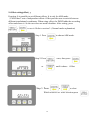
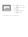
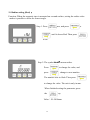
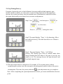
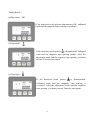
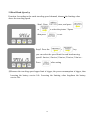
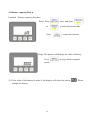
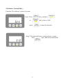
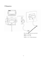
PMLD User’s Manual
1
Content
1. Installation -----------------------------------------------------------------------------------03
2. Functions ------------------------------------------------------------------------------------04
3. LCD Panel Description --------------------------------------------------------------------05
4. Key Pad description ------------------------------------------------------------------------06
5. Function Mode ------------------------------------------------------------------------------07
6. Base Point/Origin(Org) ------------------------------------------------------------------08
7. Direction (Dir) ----------------------------------------------------------------------------10
8. Resolution (Dot) --------------------------------------------------------------------------11
9. Offset setting (Offset) ----------------------------------------------------------------------12
10. Scale (Scale) -------------------------------------------------------------------------------14
11. Radius setting (Rad) ----------------------------------------------------------------------15
12. Gap Tuning (Tune)------------------------------------------------------------------------16
13. Read Head (Speed)
----------------------------------------------------------------19
14. Battery capacity (Bat)---------------------------------------------------------------------20
15. Software Version (Edit) ------------------------------------------------------------------21
16. Parameter default -------------------------------------------------------------------------22
17. Dimension ---------------------------------------------------------------------------------23
18. Appendix ----------------------------------------------------------------------------------24
2
1. Installation
1.At installation, the position of read-head is important.
Roll
Gap
Pitch
Yaw
Nominal gap is 1mm
M3 screws positions
☆☆2.Gap Tuning: (Waring)
In order to guarantee the Accuracy, the Gap Tuning refers to P.15 must be done,after the
machine new installment or read head to have the again disassembly movement.
3
2. Functions
(1).Switching between ABS and REL. See appendix.
(2).Units of measurement: mm/inch/deg
(3).Base point (Origin) coordinate setting
(Setting of the coordinate where it stops at the moment.)
(4).Counting direction setting (increase/decrease)
(5).Resolution setting (decimal point setting)
mm=(0.005, 0.01, 0.1, 1); inch=(0.0001, 0.001, 0.01, 0.1);
deg=(0.001, 0.01, 0.1, 1)
(6). 5 sets of offset settings. See appendix.
(7). Programmable scaling factor.
(8). Diameter setting for arc measurement. (The smallest radius is 50mm.)
(9). Gap adjustment assistant (For better installation.)
(10).Rated velocity setting (Maximum speed)
(11).Battery condition display
(12).Key lock
Specifications
◎LCD 8 digits display
◎Use two 1.5 V AA Type battery(No. 3 battery)
◎Max. gap between read head and tape 2.0mm
◎Operation: 4 keys
◎Temperature for stocking:-5~+65 oC
◎Operation temperature: 0~+50 oC
◎Battery life circa one year (Assumed speed is set to 1.5 m/sec or below)
4
3. LCD display panel
︰5 sets of ABS counter
-see appendix
:gap too big
︰5 sets of REL counter
-see appendix
:gap too short
:degree
:blinking (gap not adjusted)
:mm
:gap is proper
:inch
:ABS mode
:Radius setting
:REL (INC) mode
:Radius value
:Battery low
:Key locked
:minus
:bad flatness
NO SEN : read head is away from tape
5
4. Key operations
◎ Normal mode
The meaning of key at the Normal mode:
:Menu
:Switching between ABS/REL mode
:Switching between units (mm/inch/degree)
:Set to zero (only for REL mode)
+
+
:Lock and unlock the key
:
ABS mode: switching ORG
REL mode: switching CNT
6
5. Function Mode
At normal mode, press MENU to enter function mode.
The meaning of key at the Function mode:
:Return to normal mode/Back one page
: Switching between functions
Org>Dir>Dot>Offset>Scale>Rad>Tune>Speed>Bat>Edit>Org
: Switching between functions
Org>Edit>Bat>Speed>Tune>Rad>Scale>Offset>Dot> Dir>Org
:Confirmation key
7
6. Base point (origin) setting (Org)
Function: This is to set the origin coordinate. (It sets the coordinate where it stops at the
moment.) User can set the value according to need. It can be zero or non-zero. If it is zero, it
is origin. This is only for ABS mode.
Step 1. If not in ABS mode, press
switch into ABS mode.
Step 2. Press
or
once, then press
until it shows Org.
Step 3. Press
8
to enter setting.
to
Step 4. Press
to set the sign. Press
Then press
or
to switch between digits
to change and the digits will blink. Press
or
to change value (0-9).
After change is done, press
to
confirm.
The display will show the newly set value
Note: The setting range is -360°~+360° at the angle mode.
Note: PMLD has 5 sets of independent offsets, be make sure the offset value
corresponding to the set is 0, or the PMLD adds the according offset to origin
coordinate and shows it.
Note: If parameter is over the setting range, it will shows an ”Error”.
9
7. Counting direction (Dir):
Function: It is possible to set the direction for incremental signal.
Step1.Press
,than press
or
to enter setting.
Step2.Press
Press
to enter setting, than
or
to choose
counting direction (positive or negative),
than press
10
8. Resolution setting (Dot)
Function: It is possible to set the resolution according to user’s requirement.
1. For mm, possible choices are 0.005, 0.01, 0.1, 1mm.
2. For inch, possible choices are 0.0001, 0.001, 0.01, 0.1 inch.
3. For degree, possible choices are 0.001, 0.01, 0.1, 1 degree.
Step 1. Press
to choose the unit needed.
Step 2. Press
once, and press
or
until it shows Dot.
Step 3. Press
to enter setting. Press
to choose the resolution needed. Finally, press
to confirm.
11
9. Offset setting(offset):
Function: It is possible to set different offsets. It is only for ABS mode.
(PMLD has 5 sets of independent offsets. Offset provides user to switch between
different translational coordinates. When using offset, the PMLD adds the according
offset and shows it. So the user does not need calculator. After setting, press
+
to use it. Refer to section 3. (Normal mode explanation)
Step 1. Press
Step 2. Press
to choose ABS mode.
once, then press
or
until it shows
Offset
.
Step 3. Press
or
to select
Which offset to set. After selection press
12
Step 4. Press
press
to set the sign. Then
to switch to next digit.
the digit will blink.
Press
to change the value,
Press
to confirm.
.
Note: The setting range is -360°~+360° at the angle mode.
13
10. Scale (Scale):
Function: It is possible to set to a different scale for coordinate display.
Step 1. Press
or
once, and press
until it shows Scale.
then press
Step 2.Press
to enter setting.
to change the blinking digit.
Press
to change to next digit.
Press
to change the value.
Finally press
to confirm.
Range: 0.01~1000.00(Not including 0)
14
11. Radius setting (Rad):
Function: When the magnetic tape is mounted on a round surface, setting the radius value
makes it possible to show the correct angle.
Step 1. Press
once, and press
or
until it shows Rad. Then press
to set.
Step 2. The symbol
means radius.
Press
to change the value, and
press
change to next number.
The number will be flash. Then press
to change the value. The unit is only in mm.
When finished setting the parameter, press
the
key.
Value:50~5000mm.
15
12. Gap Tuning(Tune):
Function: Assists the user to check distance between read head and magnetic tape
installs whether suitably, as well as the revision feeling did measure the signal may
increase the system accuracy, after the machine new installment or read head to have
the again disassembly movement, best recreates an adjustment
Step1. Press
,and next press
or
to select tune.
Press to
setting the value。
Step2. The panel display “Tune-“ is for detecting. Move
the read head slowly. The shift should be over 30mm in
10 second.
Step3. The panel display ”Tune --“will follow
closely. The display goes back to normal mode when
detect finished and will show if the gap is too big, too
small or ok. The message knows the gap between read
head and magnetic tape.
※ This movement must be complete in 30 seconds, if 30 seconds passes without
completing the system tune, the automatic rebound general pattern reduces the power
consumption. This time the picture indicates
span adjustment not yet completes.
Note: After completing the span adjustment movement, you must establish the reference
point.
16
Tuning Result:
(a)Gap status:OK
If the detection result picture demonstrates OK, indicated
reads and the magnetic tape spacing is moderate.
(b)Gap small:
If the detection result picture is demonstrated, indicated
reads and the magnetic tape spacing smaller. After the
adjustment reads and the magnetic tape spacing, you must
recreate Tune the movement.
(c) Gap large:
If the detection result picture
is demonstrated,
indicated reads and the magnetic tape spacing is
oversized. After the adjustment reads and the magnetic
tape spacing, you must recreate Tune the movement.
17
(d) Flatness unstable:
If
detection
result picture
is
shown,
the
mechanical flatness is not smooth, improve the
mechanical flatness, you must recreate Tune the
movement
Trouble shooting:
(a) Turning Trouble
If the picture show “Tune- or Tune--“ for too long, the
Gap may be too high or the signal of the read
head is unstable. Please press
work.
This time the picture is
to finish the
Indicates the span
adjustment is not yet complete. After reducing reads a
spacing, recreate the Tune movement, if it still has not
been improved, please inspect whether the signal reads
normal.
※ After completing the Tune movement, the system can remember automatically , this
signal revision related parameter.If this period has the replacement battery after starting,
picture
may appear, although not affecting the system precision. It is suggested to
make time for the Tune the movement.
18
13.Read Head (Speed):
Function: According to the reads traveling speed demand, chooses the limiting value
above the traveling speed.
Step1. Press
or
once, and press
to select the picture “Speed”
then press
to set.
Setp2. Press the
or
key.
you can select the speed limit for read head moving
speed.1.0m/sec,1.5m/sec,2.0m/sec,2.5m/sec,3.0m/sec .
Press
after setting
※Because the traveling speed upper limit is bigger, the power consumption is bigger, thus
lowering the battery service life. Lowering the limiting value lengthens the battery
service life.
19
14. Battery capacity(Bat):
Function:Battery capacity detection
Step1. Press
or
Press
once, and press
to select the picture Bat.
to enter the function.
Step2. The picture will display the value of battery.
Press
mode .
key to go back to normal
※ If the value of the battery is under 2, the display will show the picture
change the battery.
20
. Please
15.Software Version(Edit):
Function: The software version of system
Step1. Press
or
once, and press
until it shows “Edit”.
press
to enter the function.
Step2. The panel will show current software version.
Press
once, and back normal mode.
21
16.Parameter default:
Function
Dot
Description
Resolution
Dir
Org
Offset
Scale
Rad
Speed
Direction
Origin
Origin offset
Scale
Radius
Speed limit
Default
(1).0.005mm
(2).0.0001inch
(3).0.001
Pos
0
0
1.00
50mm
1.5 m/sec
22
17.Dimension:
By customer to order the sensor head:
PM-A-□□-□A-E-00
PM-A-□□-□A -I-00
PM-B-□□-□A -□-00(development)
23
18.Appendix:
(1).Panel display and function antithesis:
LCD
name
name
display
0
name
1
LCD
display
3
name
LCD
display
9
name
LCD
display
F
LCD
display
name
name
LCD
display
name
LCD
display
8
LCD
display
name
name
LCD
display
B
LCD
display
name
D
LCD
display
LCD
display
5
A
C
name
LCD
display
name
7
LCD
display
name
2
4
6
name
LCD
display
name
LCD
display
E
LCD
display
name
G
name
H
24
LCD
display
name
LCD
display
J
I
name
LCD
display
L
name
LCD
display
R
name
LCD
display
X
LCD
display
name
name
LCD
display
name
LCD
display
Q
LCD
display
name
name
LCD
display
T
LCD
display
name
V
LCD
display
LCD
display
N
X
U
name
LCD
display
name
P
LCD
display
name
K
M
O
name
LCD
display
name
name
LCD
display
W
LCD
display
name
Y
name
Z
25
LCD
display
(2).Technical description:
(a).Absolution mode:
Distance
0
The same origin, you can not change the origin position.
(b).Relation mode:
Distance
0
You can change any origin by your demand.
(c).ORG (ORG0、ORG1、ORG2、ORG3、ORG4) description:
In the woodworking machine application, it does not cuts the same length by user
discretion. (Example: 1 meter and 2 meters, following under description)
ORG0
1meter
ORG1
2meter
0
26
The user only changes the setting of the origin. (You need 1 meter that sets
ORG0 for 1 meter origin, and for 2 meters, set ORG1 for 2 meter origin.)
This function can increase the efficiency in measurement above 2 sizes.
(d).CNT(CNT0、CNT1、CNT2、CNT3、CNT4)description:
In the woodworking machine application, it cuts not the same length on same wood.
(Example: 30 centimeters and 40 centimeters, following under description)
30cm
30cm
CNT0
40cm
CNT0
CNT1
0
0
0
The user only changes the CNT setting. User can direct the read out the position
and cuts the wood. They don’t need to set the parameter once again.
(e).Origin compensation:
You can not change the position of origin in absolute mode. If you need to change
the position of origin, you must use the origin compensation to offset the position
of origin.
(3). PMLD User’s Manual Version:
Please carefully read the user’s manual before using this product. We don’t take
responsibility for any damage possibly caused by those who didn’t follow these notes
to install. This PMLD User’s Manual Version is VER 1.1 .
27