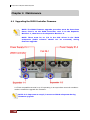
1
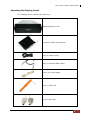
64 Bays SAS to SAS/SATA JBOD Subsystem User Manual Revision 1.1 64 Bays SAS to SAS/SATA JBOD Subsystem Table of Contents Preface ................................................................................................................................3 Before You Begin .............................................................................................................4 Safety Guidelines............................................................................................................................................................... 4 Controller Configurations .............................................................................................................................................. 4 Packaging, Shipment and Delivery ............................................................................................................................ 4 Unpacking the Shipping Carton ............................................................................................................................ 5 Chapter 1 1.1 Product Introduction .................................................................................7 Technical Specifications ....................................................................................................................................... 8 Chapter 2 2.1 Identifying Parts of the JBOD Subsystem ............................................9 Main Components ................................................................................................................................................. 9 2.1.1 2.1.1.1 LCD Display Panel LED .....................................................................................................................10 2.1.1.2 HDD Status LEDs ................................................................................................................................ 11 2.1.2 2.2 Front View ........................................................................................................................................................ 9 Rear View ........................................................................................................................................................ 12 JBOD Controller Module ................................................................................................................................... 13 2.2.1 2.3 JBOD Controller Panel ............................................................................................................................... 13 Power Supply Fan Module (PSFM) ............................................................................................................... 15 2.3.1 2.4 PSFM Panel ....................................................................................................................................................17 Fan Module............................................................................................................................................................. 18 2.4.1 2.5 Turbo Fan .......................................................................................................................................................20 Expander Module ................................................................................................................................................. 21 2.5.1 2.6 Expander Module Panel ........................................................................................................................... 21 Disk Drive Installation into the Disk Slot ................................................................................................... 22 Chapter 3 Getting Started with the Subsystem................................................... 28 3.1 Installing the Rails and Mounting into Rack ............................................................................................ 28 3.2 Removing the Disk Array from the Rack ................................................................................................... 41 3.3 Preparing the JBOD and Connecting to RAID Subsystem.................................................................. 43 3.4 Preparing the JBOD and Connecting to SAS HBA in Host System ................................................ 43 3.5 Powering On ..........................................................................................................................................................44 3.6 Powering Off .......................................................................................................................................................... 45 Chapter 4 4.1 Maintenance ............................................................................................. 46 Upgrading the JBOD Controller Firmware................................................................................................. 46 2 User Manual 64 Bays SAS to SAS/SATA JBOD Subsystem Preface About this manual This manual provides information regarding the hardware features and installation of the 64Bay JBOD subsystem. Information contained in the manual has been reviewed for accuracy, but not for product warranty because of the various environment/OS/settings. Information and specifications will be changed without further notice. This manual uses section numbering for every topic being discussed for easy and convenient way of finding information in accordance with the user’s needs. The following icons are being used for some details and information to be considered in going through with this manual: NOTES: These are notes that contain useful information and tips that the user must give attention to in going through with the subsystem operation. IMPORTANT! These are the important information that the user must remember. WARNING! These are the warnings that the user must follow to avoid unnecessary errors and bodily injury during hardware and software operation of the subsystem. CAUTION: These are the cautions that user must be aware of to prevent damage to the subsystem and/or its components. Copyright No part of this publication may be reproduced, stored in a retrieval system, or transmitted in any form or by any means, electronic, mechanical, photocopying, recording or otherwise, without the prior written consent. Trademarks All products and trade names used in this document are trademarks or registered trademarks of their respective owners. Changes The material in this document is for information only and is subject to change without notice. User Manual 3 64 Bays SAS to SAS/SATA JBOD Subsystem Before You Begin Before going through with this manual, you should read and focus on the following safety guidelines. Notes about the subsystem’s controller configuration and the product packaging and delivery are also included here. Safety Guidelines To provide reasonable protection against any harm on the part of the user and to obtain maximum performance, user is advised to be aware of the following safety guidelines particularly in handling hardware components: Upon receiving of the product: Place the product in its proper location. Do not try to lift it by yourself alone. Two or more persons are needed to remove or lift the product to its packaging. To avoid unnecessary dropping out, make sure that somebody is around for immediate assistance. It should be handled with care to avoid dropping that may cause damage to the product. Always use the correct lifting procedures. Upon installing of the product: Ambient temperature is very important for the installation site. It must not exceed 30◦C. Due to seasonal climate changes; regulate the installation site temperature making it not to exceed the allowed ambient temperature. Before plugging-in any power cords, cables and connectors, make sure that the power switches are turned off. Disconnect first any power connection if the power supply module is being removed from the enclosure. Outlets must be accessible to the equipment. All external connections should be made using shielded cables and as much as possible should not be performed by bare hand. Using anti-static hand gloves is recommended. In installing each component, secure all the mounting screws and locks. Make sure that all screws are fully tightened. Follow correctly all the listed procedures in this manual for reliable performance. Controller Configurations This JBOD subsystem supports single JBOD controller configurations. Packaging, Shipment and Delivery Before removing the subsystem from the shipping carton, you should visually inspect the physical condition of the shipping carton. Unpack and verify that the contents of the shipping carton are complete and in good condition. Exterior damage to the shipping carton may indicate that the contents of the carton are damaged. If any damage is found, do not remove the components; contact the dealer where you purchased the subsystem for further instructions. 4 User Manual 64 Bays SAS to SAS/SATA JBOD Subsystem Unpacking the Shipping Carton The shipping carton contains the following: JBOD Subsystem Unit 64 pairs of HDD side brackets Two (2) Power cords One (1) External SAS cables Three (3) Serial cables One (1) Disk Tool Key of Top Cover User Manual 5 64 Bays SAS to SAS/SATA JBOD Subsystem Screws User Manual NOTE: If any damage is found, contact the dealer or vendor for assistance. 6 User Manual 64 Bays SAS to SAS/SATA JBOD Subsystem Chapter 1 Product Introduction The 64 bays EPICa JBOD Subsystem The EPICa EP-4643J-S6S6 is a 19-inch 4U rackmount JBOD unit. It features the latest SAS2 (6Gb/s) interface and designed to fit in with the environments which needed highly reliable and relentless data growth. The EP-4643J-S6S6 is also a versatile SAS2 / SATA3 Disk Expansion system, ideal for high capacity and scalability storage in IT demands. Based on the 6G SAS2.0 technology, the EP-4643J-S6S6 supporting the choice of SAS2 and SATA3 drive configurations to deliver the best cost-performance index with higher bandwidth. Features 64 hot-swappable drive bays in a rackmount 4U chassis Simultaneously support SAS2 or SATA3 disk Single SAS2 JBOD controller module Each SAS2 JBOD controller module consist of three mini SAS (4X) port Power Supply and cooling system contained in 1 module for efficient cooling Two 1100W redundant hot swappable power supplies Incorporates a cableless design for maximum signal integrity Utilizes industry-standard SCSI Enclosure Services to monitor enclosure and disk environmental conditions Enclosure monitoring S.E.S. support for standard enclosure management System LED indications Fan speed monitoring Power supply monitoring System voltage monitoring System temperature monitoring System alarm User Manual 7 64 Bays SAS to SAS/SATA JBOD Subsystem 1.1 Technical Specifications RAID Controller JBOD Controller option Single Host Interface One 6Gb/s SAS (SFF-8088) Disk Interface 6Gb/s SAS, 6Gb/s SATA SAS Expansion Two 6Gb/s SAS (SFF-8088) - Direct Attached 64 Disks - Expansion Refer to RAID controller specification Monitor Port support Yes Enclosure Platform Rackmount Form Factor 4U # of Hot Swap Trays 64 Tray Lock Yes Disk Status Indicator Access / Fail LED Backplane SAS2 / SATA3 # of PS/Fan Modules 1100W x 2 w/PFC # of Fans 15 Power requirements AC 90V ~ 254V Full Range 50Hz~60Hz Environmental Relative Humidity 10% ~ 85% Non-condensing Operating Temperature 10°C ~ 40°C (50°F ~ 104°F) Physical Dimension 900(L) x 482.6(W) x 177(H) mm Weight (Without Disk) 43.5Kg Specification is subject to change without notice. 8 User Manual 64 Bays SAS to SAS/SATA JBOD Subsystem Chapter 2 Identifying Parts of the JBOD Subsystem 2.1 Main Components 2.1.1 Front View IMPORTANT: When powering off the JBOD subsystem, turn off first the Main Switch and allow at least 3 minutes (during which each disk slot starting from slot #1 until slot #64 will be powered down) for the subsystem to shutdown properly. Then turn off the switches of the 2 Power Supply Fan Modules. User Manual 9 64 Bays SAS to SAS/SATA JBOD Subsystem 2.1.1.1 LCD Display Panel LED Part Function Power LED Green indicates power is ON. Main Switch Button Flashing Blue Indicates that the power cords are inserted and/or indicates the 2 power supply switches are turn on. Light Blue Indicates that the sytem is on. No Light Indicates that the whole system is power off. 10 User Manual 64 Bays SAS to SAS/SATA JBOD Subsystem 2.1.1.2 HDD Status LEDs The Front Panel shows the disk drives status. Activity LED Power On/Fail LED Indicator Color Description Activity LED Blue Blinking Indicates the disk drive is busy or being accessed. Green Indicates the disk drive in this slot is good. RED Indicates the disk drive in this slot is defective or failed. LED is off Indicates there is no disk drive in this slot. Power On/Fail LED User Manual 11 64 Bays SAS to SAS/SATA JBOD Subsystem 2.1.2 Rear View NOTE: Each Power Supply Module has 1 Power Supply and 5 Fans. The JBOD subsystem is logically divided into two enclosures for hardware monitoring. The functions of the Expander Modules are as follows: 12 Module: Function/Description: Expander Module 1-1 Monitors Enclosure 1 (Disk slots 1 to 32, Power Supply 01-1, Fans 01-1, 02-1, 03-1, 04-1, and 05-1, 07-1, 08-1 and Turbo Fan 06-1). Note: “-1” means enclosure 1. Expander Module 1-2 Monitors Enclosure 2 (Disk slots 33 to 64, Power Supply 01-2, Fans 01-2, 02-2, 03-2, 04-2, 052, 06-2 and 07-2). Note: “-2” means enclosure 2. User Manual 64 Bays SAS to SAS/SATA JBOD Subsystem 2.2 JBOD Controller Module JBOD Controller Module 2.2.1 JBOD Controller Panel User Manual 13 64 Bays SAS to SAS/SATA JBOD Subsystem Part Description SAS In Port Use to connect to SAS HBA or to RAID subsystem’s SAS Expansion Port. SAS Expansion Port Use to connect to the SAS In Port of another JBOD subsystem. RS-232 Port Use to upgrade the firmware of the JBOD controller. Connect the RJ11-to-DB9 serial cable to your system’s serial port. Indicator Color Description Link LED Green Indicates expander has connected or linked. Activity LED Blinking Blue Indicated the expander is busy and being accessed. 14 User Manual 64 Bays SAS to SAS/SATA JBOD Subsystem 2.3 Power Supply Fan Module (PSFM) The 64bay RAID subsystem contains two 1100W Power Supply/Fan Modules. All PSFM are inserted at the rear of the chassis. Front Panel Rear Side NOTE: Each PSFM delivers Full-Range 100V ~ 240V (+/-10%) voltage AC electricity. Each PSFM consists of 1 power supply and 5 fans. Two Fans are located at the panel side, and three fans are located in rear side of the PSFM. User Manual 15 64 Bays SAS to SAS/SATA JBOD Subsystem Power Supply 01-1 Fan 01-1 Fan02-1 Power Supply 01-2 Fan 01-2 Fan 02-2 Rear Side Front Panel NOTE: The first PSFM (01-1, on the left side of enclosure) has five fans: Fan 01-1 and Fan 02-1 on the front panel; and Fan 03-1, Fan 04-1 and Fan 05-1 on the rear side. The second PSFM (01-2, on the right side) has five fans also: Fan 01-2 and Fan 02-2 on the front panel; and Fan 03-2, Fan 04-2 and Fan 05-2 on the rear side. NOTE: “-1” means enclosure 1 and “-2” means enclosure 2. 16 User Manual 64 Bays SAS to SAS/SATA JBOD Subsystem 2.3.1 PSFM Panel Part Description AC Power Input Socket Use to connect the power cord from power source. Power On/Off Switch Use to power on or power off the PSFM. Indicator Color Description Green Indicates the power supply module is good. Red Indicates the power supply module is faulty. Red Indicates one or more fans in the PSFM has failed. Power Status LED Fan Fail LED When the power cord connected from main power source is inserted to the AC Power Input Socket the Power Status LED becomes RED. When the switch of the PSFM is turned on, the LED still shows RED. After the main switch in front panel is turned on, the LED turns GREEN, which means it is functioning normally. The PSFM has a 5V standby DC voltage. When the power cord(s) is/are connected to the AC Power Input Socket, after 1 second, all Activity LEDs will flash once. When the power cord(s) is/are disconnected from AC Power Input Socket, after 3 seconds, all Activity LEDs will flash twice. User Manual 17 64 Bays SAS to SAS/SATA JBOD Subsystem 2.4 Fan Module The 64bay RAID subsystem contains 15 fans. Power Supply 01-1 Power Supply 01-2 Turbo Fan 06-1 Fan 01-1 Fan02-1 Fan 01-2 Fan 02-2 NOTE: “-1” means enclosure 1 and “-2” means enclosure 2. 18 User Manual 64 Bays SAS to SAS/SATA JBOD Subsystem Indicator Color Description No light Indicates the fan is normal. Red Indicates the turbo fail is faulty. Fan Fault LED User Manual 19 64 Bays SAS to SAS/SATA JBOD Subsystem 2.4.1 Turbo Fan The turbo fan (Fan 06-1) provides additional airflow inside the enclosure. Turbo Fan LED Status LED Indicator Color Description Status LED Red Indicates the turbo fail is faulty. NOTE: The status of Turbo Fan (Fan 06-1) is monitored by Expander Module 1. 20 User Manual 64 Bays SAS to SAS/SATA JBOD Subsystem 2.5 Expander Module The Expander Module contains the SAS expander. It can be used to upgrade the SAS expander firmware. It also contains the SES module (SCSI Enclosure Services). SES is the protocol used for enclosure environmental control. The SES module monitors the following enclosure conditions: temperature, power supply voltage, and fan speed. 2.5.1 Expander Module Panel Activity LED RS-232 Port Fault LED Part Description RS-232 Port Use to upgrade the firmware of the expander module. Connect the serial cable RJ11-to-DB9 to your system’s serial port. Indicator Color Description Activity LED Blinking Green Indicates the expander module is busy or active. Fault LED Binking Red Indicates the expander module is faulty or has failed. User Manual 21 64 Bays SAS to SAS/SATA JBOD Subsystem 2.6 Disk Drive Installation into the Disk Slot This section describes the physical locations of the hard drives supported by the subsystem and give instructions on installing a hard drive. NOTE: When the Disk Array is shipped, the disk trays are not placed in the disk slots. If all disk trays will be used to install all 64 disk drives, for quicker and easier installation of disk drives in the Disk Array, it is recommended to attach first each disk drive with HDD side brackets. Slot 61 Slot 1 Slot 64 Slot 4 DISK SLOT NUMBERS Rear side 61 57 53 49 45 41 37 33 29 25 21 17 13 9 5 1 62 58 54 50 46 42 38 34 30 26 22 18 14 10 6 2 63 59 55 51 47 43 39 35 31 27 23 19 15 11 7 3 64 60 56 52 48 44 40 36 32 28 24 20 16 12 8 4 Front Side 22 User Manual 64 Bays SAS to SAS/SATA JBOD Subsystem To install a SAS disk drive or SATA disk drive 1. Prepare the HDD side brackets. Remove them from the dummy disk by pushing the upper sides of the dummy disk as shown below: User Manual 23 64 Bays SAS to SAS/SATA JBOD Subsystem 2. Place the brackets on both sides of the disk drive and secure them with screws. 3. Place the slotted flat head screw. 24 User Manual 64 Bays SAS to SAS/SATA JBOD Subsystem 4. Place the drive carefully in the disk slot. User Manual 25 64 Bays SAS to SAS/SATA JBOD Subsystem 5. Fix the disk drive using the disk tool that is included in the package. 6. Repeat the same steps for the rest of the disks. 26 User Manual 64 Bays SAS to SAS/SATA JBOD Subsystem Note: You can use also the disk tool to remove the disk drive in the disk slot. User Manual 27 64 Bays SAS to SAS/SATA JBOD Subsystem Chapter 3 Getting Started with the Subsystem 3.1 Installing the Rails and Mounting into Rack NOTE: At least two persons are needed to lift the Disk Array. To reduce the weight of the Disk Array, remove the power supply modules from the rear of Disk Array. If disk drives are already installed in the disk trays, remove also the disk trays. Refer to appropriate sections on how to remove the power supply modules and how to remove the disk trays/disk drives. NOTE: The sample model used in the following installation might not be the actual model for this manual. NOTE: The Disk Array must be installed near the Disk Array or host system where it will be connected. A Phillips screwdriver is needed in installation. WARNING! It is prohibited to put other enclosures on top of the 64-bay Disk Array because the total weight will not be supported by the rails. Steps: 1. Open the rail box. 2. Remove the 2 rail assemblies and the screws/accessories from the box. Check its contents. 28 User Manual 64 Bays SAS to SAS/SATA JBOD Subsystem 3. Insert three (3) M5 nuts on the 2 holes of the front left side of the rack post. 4U Position of M5 nuts on the 3 holes of left rack post Rack Post – Front Left Side 4. Insert three (3) M5 nuts on the 2 holes of the front right side of the rack post. 4U Position of M5 nuts on the 3 holes of right rack post Rack Post – Front Right Side User Manual 29 64 Bays SAS to SAS/SATA JBOD Subsystem 5. Prepare the 2 rail assemblies. Front Side of Rail Assembly Rear Side of Rail Assembly 6. Hold one rail assembly and install in the front left side of rack. To install, align and insert the 2 latches of the rail into the 2 holes on the rack post. Use the Lock Lever to lock the rail assembly in the left rack post. Lock Lever Lower M5 nut View from Front Side of Front Left Rack Post Lock Lever is Not Locked 30 User Manual 64 Bays SAS to SAS/SATA JBOD Subsystem Lock Lever View from Front Side of Front Left Rack Post Lock Lever is Locked 6th Lock 5th 2 Latches 4th 3rd 2nd 1st Lower M5 Nut View from Rear Side of Front Left Rack Post 2 Latches are inserted in the 4th and 6th holes from bottom (M5 nut) User Manual 31 64 Bays SAS to SAS/SATA JBOD Subsystem 7. Install the other end of rail assembly to the left rear side. Align and insert the 2 latches on the 2 holes on the rear rack post, and then push the rail a little towards the rear side and lock the lock lever on the rack post. Lock Lever Latches View from Rear Side of Rear Left Rack Post Lock Lever Latches View from Rear Side of Rear Left Rack Post Lock Lever View from Rear Side of Rear Left Rack Post 32 User Manual 64 Bays SAS to SAS/SATA JBOD Subsystem 8. Repeat step 6 to install the other rail assembly into the right front side. Lock Lever Lower M5 nut View from Front Side of Front Right Rack Post Lock Lever is Not Locked Lock Lever Lower M5 nut View from Front Side of Front Right Rack Post Lock Lever is Locked User Manual 33 64 Bays SAS to SAS/SATA JBOD Subsystem 6th 2 Latches Lock 5th 4th 3rd 2nd Lower M5 nut 1st View from Rear Side of Front Right Rack Post 2 Latches are inserted in the 4th and 6th holes from bottom (M5 nut) 9. Repeat step 7 to install the other end of rail assembly to the rack post of rear right side. Lock Lever Latches View from Rear Side of Rear Right Rack Post 34 User Manual 64 Bays SAS to SAS/SATA JBOD Subsystem Latches Lock Lever View from Rear Side of Rear Right Rack Post Latches Lock View from Rear Side of Rear Right Rack Post User Manual 35 64 Bays SAS to SAS/SATA JBOD Subsystem 10. Pull the 2 middle rail members out from the rail assembly. Front Left Side Rear Left Side Middle Rail Member of Rail Assembly on Left Side of Rack Right Front Side Front Side View from Rear Side 36 User Manual Left Front Side 64 Bays SAS to SAS/SATA JBOD Subsystem 11. With at least 4 persons carrying the enclosure, insert the 2 inner rails (attached to the sides of the enclosure) into the middle rails. Slide the enclosure until it stops or about half way through. NOTE: Be careful when inserting the 2 inner rails into the middle rails. The 2 inner rails must be parallel with the 2 middle rails so that 2 inner rails will insert and slide easily. Use hands to guide the inner rails when inserted into the middle rails. Inner Rail Middle Rail Inner Rail Aligned with and Inserted into the Middle Rail Important: Make sure to hold the enclosure firmly in level position while inserting the enclosure in the rail. Keep holding the enclosure moved inside the rack. When the half rear side is inside the rack, you can put down the two rear handles but support in the bottom part of the enclosure is still needed so that the enclosure will not drop down. User Manual 37 64 Bays SAS to SAS/SATA JBOD Subsystem View from Rear Side 12. Press outwards the blue locks on both sides of the inner rail members at the same time. Then push the enclosure inwards (or backwards) until it goes inside the rack. Blue Lock of Inner Rail View from Right Side of Enclosure Blue Lock of Inner Rail is Pushed a Little Outwards and Enclosure is Pushed Inwards 38 User Manual 64 Bays SAS to SAS/SATA JBOD Subsystem View from Rear Side of Rack Cabinet Enclosure is Pushed Inwards 13. Insert the power supply modules. User Manual 39 64 Bays SAS to SAS/SATA JBOD Subsystem 14. Use six (6) M5 screws to lock the enclosure into the rack post, one screw in each corner. Note that the screw driver will need to pass through the corner hole of front panel for the two upper corner holes on both sides. Corner Hole Screw Front Left Side Front Right Side 15. Open the top cover and re-insert the disk drives / disk trays, if disk drives/disk trays were previously removed. Then close the top cover. 40 User Manual 64 Bays SAS to SAS/SATA JBOD Subsystem 3.2 Removing the Disk Array from the Rack 1. Remove the six screws in the front corner. Front Left Side Front Right Side 2. Remove the power supplies in the rear and the disk drives from the disk slots. User Manual 41 64 Bays SAS to SAS/SATA JBOD Subsystem 3. Carefully pull the subsystem. 4. Push the white lock to release the subsystem from the rail. 42 User Manual 64 Bays SAS to SAS/SATA JBOD Subsystem 3.3 Preparing the JBOD and Connecting to RAID Subsystem 1. Install the disk drives, if not yet installed. Refer to Section 2.6 Disk Drive Installation for detailed information. 2. Connect one end of SAS cable to the SAS In Port of the JBOD subsystem enclosure and the other end to the SAS Expansion Port of the RAID subsystem enclosure. 3.4 Preparing the JBOD and Connecting to SAS HBA in Host System 1. Install the disk drives, if not yet installed. Refer to Section 2.6 Disk Drive Installation for detailed information. 2. Connect one end of SAS cable to the SAS In Port of the JBOD subsystem enclosure and the other end to the SAS HBA on the Host system. User Manual 43 64 Bays SAS to SAS/SATA JBOD Subsystem 3.5 Powering On 1. Plug in all the power cords into the AC Power Input Socket located at the PSFM. NOTE: The subsystem is equipped with redundant, full range power supplies with PFC (power factor correction). The system will automatically select voltage. NOTE: The PSFM has a 5V standby DC voltage. When the power cord(s) is/are connected to the AC Power Input Socket, after 1 second, all Activity LEDs will flash once. When the power cord(s) is/are disconnected from AC Power Input Socket, after 3 seconds, all Activity LEDs will flash twice. 2. Turn on each Power On/Off Switch of the PSFM. The main switch button in the front panel will still flashing blue. NOTE: When the power cord connected from main power source is inserted to the AC Power Input Socket, the Power Status LED becomes RED. When the switch of the PSFM is turned on, the LED still shows RED. After the main switch in front panel is turned on, the LED turns GREEN, which means it is functioning normally. Power Supply 01-1 44 User Manual Power Supply 01-2 64 Bays SAS to SAS/SATA JBOD Subsystem 3. Push the main switch button in the front panel to power on. Main Switch 4. Allow the machine a few moments to initialize before using it. The main switch button will continue flashing blue until the system is finished checking each disk slot. NOTE: The system will initialize after turning on the Main Switch. Each disk slot will be checked during subsystem initialization. 5. Configure RAID using the utility options described in the next chapter. 3.6 Powering Off IMPORTANT: When powering off the Disk Array, turn off first the Main Switch in the front panel and allow at least 3 minutes for the subsystem to shutdown properly. During this time, each disk slot starting from slot #1 until slot #64 will be powered down. The main switch button in the front panel will flash blue. When Disk Array has totally powered down, turn off the switches of the 2 Power Supply Fan Modules at the rear. The main switch button in the front panel will still flash blue until the power cords are pulled out from the sockets. User Manual 45 64 Bays SAS to SAS/SATA JBOD Subsystem Chapter 4 Maintenance 4.1 Upgrading the JBOD Controller Firmware NOTE: The JBOD firmware upgrade procedure must be done three times. First is on the JBOD Controller, next is on the Expander Module 1-1, then last on the Expander Module 1-2. NOTE: There must be no I/O in the disk drives in the JBOD subsystem (RAID volumes should not be accessed) during firmware upgrade. 1 2 3 A VT100 compatible terminal or a PC operating in an equivalent terminal emulation mode is needed to upgrade the firmware. NOTE: It is important to stop I/O access to JBOD subsystem during firmware upgrade. 46 User Manual 64 Bays SAS to SAS/SATA JBOD Subsystem 1. Please use the RS232 cable (RJ11 to DB9) to JBOD Controller #1 and to connect JBOD RS232 Port and PC COM1 Port (or change to other COM Port as necessary). 2. Open Windows HyperTerminal Program. Connect using COM1 (COM Port used in Step1), Baud Rate: 115200, n, 8, 1, Flow Control: None. 3. Press the Enter key and the password prompt will be displayed. 4. Key in the password (Default password: 00000000) to login to CLI. 5. At CLI prompt, input the command to update firmware. a. CLI> NOTE: “fdl code 0” is the command to update flash firmware code (.fw file). “fdl mfgb 0” is the command to update CFG data code (.rom file) Make sure you have both files before updating. b. CLI> fdl mfgb 0 Please Use XModem Protocol for File Transmission. Use Q or q to quit Download before starting XModem. Offset = 0x0 c. Select Function menu to transfer CFG data .rom file: “Function” Î “Transfer” Î “Send File” Î “Browse” Î “Open” and select the .rom file (for example: 8016-mfgdat6-20110131.rom) firmware folder location. Select “Xmodem” Protocol to send firmware file (Only need about 60 seconds to finish sending firmware file. If not, please repeat steps B and D again). Note. If won’t to transfer CFG data .rom file, Press Q or q to quit Download before starting data transfer. d. CLI>fdl code 0 Please Use XModem Protocol for File Transmission. Use Q or q to quit Download before starting XModem. Offset = 0x0 e. Select Functon menu to transfer firmware file: “Function” Î “Transfer” Î “Send File” Î “Browse” Î “Open” and select the .fw file (for example: 8016-07.01.09.96-20110211.fw) from firmware folder location. Select “Xmodem” Protocol to send firmware file (Only need about 60 seconds to finish sending firmware file. If not, please repeat steps D and E again). Note. If won’t to transfer firmware data .fw file, Press Q or q to quit Download before starting data transfer. User Manual 47 64 Bays SAS to SAS/SATA JBOD Subsystem f. Use “reset” command to Restart JBOD or power cycle g. Re-login to JBOD CLI. h. Use “sys” command to verify JBOD firmware version. CLI>sys i. If needed, the “reset” command can also be used to restart the JBOD controller. (Normally used in single JBOD Controller mode, If already to connect to Controller ) CLI>reset 6. After upgrading the JBOD controller, connect the null modem cable to RS232 port of Expander Module 1-1. Repeat Steps 3 to 5 to update Expander Module 1-1. Don’t restart or power off the JBOD subsystem during upgrade. 7. After upgrading Expander Module 1-1, connect null modem cable to RS232 port of Expander Module 1-2. Repeat Steps 3 to 5 to update Expander Module 1-2. Don’t restart or power off the JBOD subsystem during upgrade. 8. After upgrading JBOD controller and 2 Expander Modules, power cycle (power off and power on) the JBOD subsystem. 9. Re-login to CLI. 10. Verify if firmware version has been updated. CLI>sys 48 User Manual (Command to verify JBOD firmware version)