1
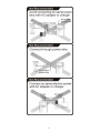
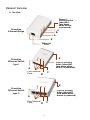
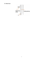
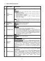
PLC Device
User Manual
Powerline
Ethernet
Bridge +
Switch
¾ 200 Mbps
¾ World’s smallest
¾ Green product
¾ Standby mode
¾ Best Performance
Powerline Ethernet Bridge
Powerline Ethernet Switch
V. 1.0.4
TABLE OF CONTENT
ORDERING INFORMATION .............................................................................................................................. 2
INCLUDED ITEMS ........................................................................................................................................... 3
IMPORTANT SAFETY INSTRUCTIONS ............................................................................................................. 4
FIRST THING TO KNOW BEFORE INSTALLATION ............................................................................................ 5
AC outlets connection .................................................................................................................... 5
Connection via power strip ........................................................................................................... 7
Electrical interference..................................................................................................................... 7
Electrical wiring................................................................................................................................ 7
PRODUCT OUTLOOK ..................................................................................................................................... 8
PRODUCT OVERVIEW .................................................................................................................................. 11
Standby Mode ................................................................................................................................. 11
PRODUCT INSTALLATION ............................................................................................................................. 12
Setting logical network group .................................................................................................... 12
Remove a device from a logical network Group ................................................................... 13
Setting different network Group ................................................................................................ 13
Application 1 – local Powerline network among PCs .......................................................... 14
Application 2 – PC to xDSL router connection ...................................................................... 16
Application 3 – Wireless Access Point range extensions .................................................. 18
Special Care for business installation ..................................................................................... 19
SPECIFICATIONS.......................................................................................................................................... 20
FAQ (Frequently Asked Questions) .................................................................................................. 21
TROUBLE SHOOTING ................................................................................................................................... 24
1
ORDERING INFORMATION
This PLC Device user manual describes Powerline to Ethernet Bridge and
Powerline to Ethernet Switch devices. PLC stands for Powerline
Communication.
The Powerline to Ethernet Bridge device converts the Ethernet packets from its
Ethernet port to the Powerline Communication packets (PLC packets), which then
run on home electrical power lines, and converts the PLC packets back to Ethernet
packets.
The Powerline Ethernet Switch device is a four-port Ethernet Switch device
bridged together with the Powerline communication interface. It converts the
Ethernet packets from any of its Ethernet port to PLC packets, and from PLC
packets back to Ethernet packets. Also, Ethernet packets between any two of the
four Ethernet ports are communicable, just like a normal Ethernet switch.
See the following table for a summary.
Categories
Description
Powerline Ethernet Bridge
It sends any packets from its Ethernet port
to the Ethernet port of the other Powerline
Ethernet Bridge. It converts from Ethernet
packets to be transmitted via home electric
wires to the other PLC device.
Powerline Ethernet Switch
The Powerline Ethernet Switch device
sends any packet from any of its Ethernet
port to the other three Ethernet ports of
itself, or to the Ethernet port of a remote
Powerline Ethernet Bridge device.
2
INCLUDED ITEMS
POWERLINE
ETHERNET
BRIDGE
POWERLINE
ETHERNET
SWITCH
POWERLINE ETHERNET
SWITCH + POWERLINE
ETHERNET BRIDGE
DUAL PACKAGE
SINGLE
COMBO PACKAGE
PACKAGE
DEVICE
Two devices
One device
Combined devices
Two
One
Two
ETHERNET
CABLE
3
NOTICE: This product complies with IC: ICES-006; en conformité avec IC: NMB-006
IMPORTANT SAFETY INSTRUCTIONS
This product is intended for connection to the AC power line. For installation
instructions, refer to the Installation section. The following precautions should be
taken when using this product.
z
z
z
z
z
z
z
z
z
z
z
z
Please read all instructions before installing and operating this product.
Please keep all instructions for later reference.
Please follow all warnings and instructions marked on the product.
For safety reason, when device is being powered on, this product should
NOT be installed in any electric socket which makes the surface with
venting holes on the product to face downward (facing the floor).
Unplug the Powerline device from the wall outlet before cleaning. Use a
dry cloth for cleaning. DO NOT use liquid cleaners or aerosol cleaners.
DO NOT operates this product near water.
This product should never be placed near or over a radiator, or heat register.
This product relies on the building’s electrical installation for short-circuit (over
current) protection.
DO NOT allow anything to rest on the product interconnect plug. DO NOT
locates this product where people may walk on the cords.
Because this product sends data over the power line, it is recommended that
you plug directly into a power outlet. Do not plug the device into a UPS or
power strip with surge protection. The product has its own power filter for
protection against surges.
Only a qualified technician should service this product. Opening or removing
covers may result in exposure to dangerous voltage points or other risks.
Unplug the product from the wall outlet and refer the product to qualified
service personnel for the following conditions:
¾
¾
¾
¾
When the interconnect cords are damaged or frayed.
If liquid has been spilled into the product.
If the product has been exposed to rain or water.
If the product does not operate normally when the operating instructions
are followed.
¾ If the product exhibits a distinct change in performance.
4
FIRST THING TO KNOW BEFORE INSTALLATION
This Powerline device sends data to and from each other over the existing
electrical wiring in your home, and may be affected by electrical noises or the
length of the wiring at your house. Keep the following in mind when placing this
Powerline device at home.
AC outlets connection
Avoid connecting this device to an uninterruptible power supply (UPS) or backup
power supply device. For best results, we recommend connecting the adaptors
directly to a wall outlet. Avoid connecting high power-consumption appliances to
the same wall outlet. Plug these power consuming devices onto a noise filtering
power strip to prevent these device interfere with this Powerline device. See the
following illustration figure:
For better performance, the following connection is recommended, although not
isolate with Noise filter power strip will still work OK.
The following connections are NOT recommended, although current PLC
technology will overcome most noise interference from electronic devices’ AC
adapters or chargers.
5
6
Connection via power strip
If you must connect this device to a power strip, please keep the following
recommendation in mind:
• Make sure the power strip does not have a noise filter or a surge protector, as
these features may impair communication signaling of the Powerline device sent
over the electric wiring, and its throughput or distance will be degraded.
• Use a power strip with an AC cord that is as short as possible.
• Do not connect the adaptor to a power strip that receives power from another
power strip.
Electrical interference
Certain electrical devices emit electrical noise. If this noise is spread over to the
electrical wiring in your home, it may interfere with the performance, speed, and
reliability of this device. For best results, we recommend connecting an electrical
noise filter to noise emitting appliances.
The following appliances are more likely to produce noise:
• Battery chargers (including cell phone chargers)
• Hair dryers
• Power drills
• Halogen light
• vacuum cleaner
Additionally, this product may interfere with the following appliance:
• Lights or lamps which have a touch-sensitive on/off feature
Electrical wiring
This device sends data to and from each other over the existing electrical wiring of
your house. If two wall outlets are separated by a great distance of electrical wiring,
these devices may not communicate well with each other. For more information,
refer to the troubleshooting section.
7
PRODUCT OUTLOOK
A. Top View
Face of
Venting holes
(shouldn’t
face down
when device
is powered)
Powerline
Ethernet Bridge
C
B
A
E
Ethernet
Port
E
Powerline
Ethernet Switch
type I
Face of Venting
holes (shouldn’t
face down when
device is powered)
A
Four Ethernet
Ports
B
C
E
Powerline
Ethernet Switch
type II
Face of Venting
holes (shouldn’t
face down when
device is powered)
A
Four Ethernet
Ports
D
C
8
B. Side View
9
C. Button/LED Descriptions
Item name
Description
ON: Powerline Link detected but no powerline traffic.
A
B
PLC
Link/Activity
LED
Ethernet
Link/Activity
LED
C
POWER LED
D
HomePlug 1.0
Detected LED
E
F
BLINKING:
1. Fast blinking (0.06 s ON/ 0.06 s OFF): Powerline data rate
higher than 60Mbps.
2. Normal blinking (0.2 s ON/ 0.2 s OFF) Powerline data rate
between10Mbps to 60Mbps.
3. Slow blinking (1 s ON1/ 1 s OFF): Powerline data rate
slower than 10Mbps.
OFF: Powerline Link not detected (either other devices in same
network is too far to communicate or it is alone in its logical
network).
ON: Ethernet Link Detected.
BLINKING: Ethernet traffic detected.
OFF: No Ethernet Link detected.
ON: Power on and ready.
BLINKING:
1. (blink at slower rate) means Standby mode, or
2. During Group pairing procedure. In this procedure, the
device joining or being joined into same logical network will
continue 2 minutes’ blinking, until the procedure succeeds or
is canceled). To enter or cancel Group pairing procedure,
just press the GROUP button 2~3 sec.
OFF: Power off.
BLINKING: HomePlug 1.0 Traffic detected.
OFF: HomePlug 1.0 not detected.
Press 10 seconds: clear the current and randomly generate a
new network group name.
Press 2 to 3 seconds: this will enter Group pairing procedure.
In this procedure, the device starts joining into a logical network
GROUP
of other device or announcing its network group name for other
Button
devices to join. This maximum two-minute procedure
automatically ends when it succeeds or is manually stopped.
Press this button 2 to 3 seconds will manually stop the
procedure.
Press the button when the device is powered on (not standby)
to recover all Factory default settings (including PLC network
group name).
Every new PLC devices’ factory default PLC network group
RESET Button name is HomePlugAV. During trouble shooting powerline
network communication and network group assignment, doing
this to every PLC devices will make each device return to
default network group, thus ensure their mutual
communicability.
10
PRODUCT OVERVIEW
This Powerline device is virtually an Ethernet cable replacement and an Ethernet
hub replacement. Two of these Powerline Ethernet Bridge (or one bridge and one
switch) devices replace an Ethernet cable, for connecting any PC to another PC,
PC to a DSL/cable router, or a wireless AP to a DSL device. Many of this devices
can be connected together to form a mesh communication. For example, three
computers can connect to a DSL/cable router for accessing internet via four of
these Powerline devices, each computer connects to one powerline device and the
DSL/cable router to a fourth Powerline device.
Each Powerline device has predefined attributes such as DAK (device password)
and Powerline logical network group. Any device node in a logical network group
can communicate to any of the other nodes in the same group. Devices in different
network groups won’t be able to talk to one another. Max number of nodes in a
Powerline logical network group is defined in the SPECIFICATIONS section in this
user’s manual. Powerline network group is defined by its Network Name stored in
the device. Each device is shipped with default Public network name of
HomePlugAV, and thus belong to the same logical network and be able to
communicate with each other. The GROUP button on the device can be used to
change a device’s network group attributes. For using the GROUP button, please
see first portion of the PRODUCT INSTALLATION chapter.
If user finds two newly purchased devices don’t communicate with each other,
please press the RESET button while the device is plugged (powered). This will
return the device back into factory default Powerline network group, HomePlugAV.
If these devices are still not working, please read the other sections in this user
manual for frequently asked questions and device trouble shooting.
Standby Mode
Standby mode enables the PLC device to save power consumption. The device
automatically enters standby if no Ethernet cable is connected, or the PC
connecting this device enter standby, hibernation, or powered-off over two minutes.
During standby, only POWER LED blinks at slower rate. To exit standby, insert the
Ethernet cable to the device or resume PC back to running.
Note:
1. Some computers support Wake up LAN function that it may cause our PLC can’t
enter the standby mode.
2. Some Powerline Ethernet Switch products don't support standby mode.
11
PRODUCT INSTALLATION
Setting logical network group
Users can set PLC devices into one or many logical network groups. Devices in the
same network group will communicate with each other. Devices in different
network group won’t communicate with each others. PLC devices’ network groups
are defined by its Network Name stored in the device. Each new device is shipped
with default Public network name of HomePlugAV, and thus belong to the same
logical network and be able to communicate with each other. A user can change a
number or all of these devices’ network name to form a different logical network
group for her/his own usage and keep her/his transmitted date private.
By pushing the GROUP button of a PLC device for more than 10 seconds, a
random device network name (different from HomePlugAV) will generated for this
device. This device can then ask other devices to join its network group to form
private network group. Any other devices which want to join this device’s network
group need to follow the following steps.
To make Powerline device B join device A’s logical network, do the following three
steps: (NOTE: it is more convenient to bring devices, which are to be configured
into same logical network group, side by side during this procedure. After network
group is set, the devices can be deployed anywhere at home)
Step 1. Firstly clear the logical network group of device B by pressing its
GROUP button more than 10 seconds until all LED lights simultaneously
turns off and on once. At this moment, its network group name has been
changed to a random name and ready to be assigned another network
name. At this moment, this device also can be used as a seed device so
other PLC devices can join it to form a private network group. Any
device, which wants to join this device’s network group, needs also go
through this step (Step 1).
The following steps join device B to device A ‘s logical network:
Step 2. Press GROUP Button of device A for 2 to 3 sec (make sure POWER
LED starts blinking). This makes device A to enter a maximum
two-minute Group pairing procedure, and start broadcasting its network
name and wait for another device to join its network group. This
procedure can be manually stopped by pressing GROUP button 2 to 3
12
sec.
Step 3. In less than two minutes after the above step, press GROUP Button of
device B for 2 to 3 sec (make sure POWER LED starts blinking) to
ender Group pairing procedure. After 8 ~ 10 sec, if device B is
successfully joined to Device A’s network group, the LED stop blinking
and the Group pairing procedure completes. At this moment, device B will
connect well to device A and can start to transmit data between the two
devices.
This way, Powerline device B joins same logical network as device A. Users can
join device C to device A’s logical network with same procedure. Thus device C
joins well into device A’s logical network group, and device B is also in device A’s
logical network. Thus device A, B, and C are in the same logical network group.
Users can assign as many Powerline devices into this logical same network group
as possible with the maximum number described in the SPECIFICATION section.
Remove a device from a logical network Group
For example, device A and device B are in the same logical network group, if uses
want to remove device A from this logical network group, just follow the procedure
in Step 1 by pressing GROUP button of device A for 10 seconds. This makes
device A not able to communicate with device B. If users want to remove a device
from a logical network group containing 3 or more devices, just operate the
GROUP button of this device as in Step 1.
Setting different network Group
To remove device B from the logical network of device A, just do Step 1 as above.
This way, a random network name is generated and which is different from device
A’s network name. By adding other devices to device B’s network group or to
device A’s network group using same procedures as Step 2 and 3, users can form
two groups of logical network.
The following are some application examples and their installations.
13
Application 1 – local Powerline network among PCs
Using the included Powerline devices for connecting computers in different rooms
or floors at home!
Installation procedure:
Connect the included Powerline device to a PC, such as shown in Room A of the
following two pictures. If users buy the package which includes two Powerline
devices (dual or combo package), please connect another included Powerline
device with another PC like those shown in Room B of the following two pictures. If
the user buys a single device package, which includes only one Powerline device,
she/he will be able to create Powerline network by using other HomePlug AV
bridge device at the other room (like those shown in Room B of the following two
pictures). The Room A of the second picture in the following shows multiple
network devices connect to the Powerline Ethernet Switch product, then to the
Notebook PC in Room B.
14
15
Application 2 – PC to xDSL router connection
Use the included Powerline devices for connecting multiple PC or Ethernet devices
to an xDSL router at any other room!
Installation procedure:
Connect the included Powerline device to a PC like picture shown in Room A. If
users buy the package which includes two Powerline devices (dual or combo
package), please connect another included Powerline device with a broadband
xDSL router like the picture shown in Room B. The Room A of the second picture
in the following shows multiple network devices link to the xDSL router in Room B
via a single Powerline Ethernet Switch device.
If the user buy a single device package, which includes only one Powerline device,
she/he will be able to make Powerline network by using other HomePlug AV bridge
device at the other room (like the picture shown in Room B of the following two
pictures).
16
Note: Under good power line signal conditions, Room A and Room B can be many
rooms away from each other without communication problem. (See the FAQ
section)
17
Application 3 – Wireless Access Point range extensions
Sometimes, a PC using wireless LAN on one floor of a concrete house can not
access the wireless AP router installed on different floors. Using the included
Powerline Ethernet devices will overcome this problem!
Installation procedure:
Connect the included Powerline device to a wireless Access Point like picture
shown in Room A. If users buy the package which includes two Powerline devices
(dual or combo package), please connect another included Powerline device with
a broadband xDSL router like the picture shown in Room B. If the user buy a
single device package, which includes only one Powerline device, she/he will be
able to create Powerline network by using other HomePlug AV bridge device at the
other room (like the picture shown in Room B of the following picture).
18
Special Care for business installation
We DO NOT recommend these Powerline devices for business environments due
to several uncertainties which degrade Powerline performance or block its
operation. This device has NO GUARANTEE to operate in a business environment
such as offices or factories. However many businesses will find it an inexpensive
solution to implement networking with no costly changes to wiring infrastructure.
The distance between two Powerline devices is limited by the noise in the electrical
wiring in that business environment. Interference may be intermittent, for example
highest at one time of day, or one day of the week. Normally, a business
environment covers a wider area than the recommended home application.
Electric wiring in a business environment may be very possible to involve more
than one power meter system, which sometimes cause communication difficulties
of Powerline devices.
19
SPECIFICATIONS
Items
Description
Powerline Ethernet Bridge device
200Mbps
PHY Rate
Effect Data Rate
Powerline Ethernet Switch device
TCP: Up to 91 Mbps
UDP: Up to 94 Mbps
TCP: Up to 91 Mbps
UDP: Up to 93 Mbps
Frequency Band
2~28 MHz (With Mask)
Access Methods
CSMA/CA channel-access schemes
Qos
Modulation
10/100 RJ-45 port
Four-level priority based contention access, and multi segment bursting
8-level VLAN priority field, TOS field
QoS Classification by destination MAC address and IP Port
OFDM (QAM 8/16/64/256/1024, QPSK, BPSK, ROBO)
1 port
4 ports
Distance
AC Wire : up to 300 meters
LAN Standards
IEEE 802.3, IEEE 802.3U,
HomePlug AV
PLC Standard
OS independent
Operating System
Max. dev in a
network Group
IGMP
Encryption
LEDs
Up to 63 slaves with 1 master, 64 total devices
Support for IPv4/IGMP v1,v2,v3 snooping
Support for IPv6 and MLD v1,v2 snooping
Max 16 source addresses and Group Members
128-bit AES Link Encryption with key management
1. Power (green), 2. Powerline
Activity (green), 3. Ethernet
Link/Activity (green)
1. Power (blue), 2. Powerline
Activity (blue), 3. AV/1.0 DET (blue),
0~40 ℃ (Operating); -20~60 ℃ (Storage)
Temperature
Relative Humidity
10~85% Non-Condensing (Operating)
5~90% Non-Condensing (Storage)
Power Source
100 ~ 240 VAC 50/60Hz
Power
consumption
Full load: (110 VAC) = 3.3 W; (220 Full load: (110 VAC) = 4.2W; (220 VAC)
VAC) = 3.8W; (240 VAC) = 4.2W
= 5.3W; (240 VAC) = 5.8W
Standby mode: Erp/Eup version:
Standby mode: for 4 Eth port device
(110 VAC) = 0.5W; (220 VAC) = 0.8W;
supporting standby, power consumption
(240 VAC) = 0.9W
is (110 VAC) < 1.0W; (220 VAC) < 1.7W;
Non-Erp/Eup version: Less than 1.6
(240 VAC) < 1.8W
W for Europe/UK/US
Certification
CE, CE-LVD, FCC Class B, Rohs
20
FAQ (Frequently Asked Questions)
1.
What is the distance this device can transmit?
ANS: Powerline technology provides reliable coverage for considerable distances
in a home, but noises from your home electrical appliances which is introduced into
your home's electrical wires is a limiting factor for the transmission distances. Thus
you may get (considerably) less or more coverage depending on how many
electrical appliances being used at the time your running these devices. Please
check the maximum distance under good AC wire conditions in the SPECIFICATIONS
section.
2.
What is the throughput this device can transmit?
ANS: The device’s throughput depends largely on several factors: (1) the distance
with another device, (2) interference by other appliances, (3) number of same
Powerline devices which share the common electric wiring, and (4) application
packet types – TCP or UDP. TCP applications will be slower than UDP applications.
Longer distance, larger interference, or more Powerline devices will reduce the
data throughput. The maximum throughput between two devices for TCP and UDP
are specified in the SPECIFICATIONS section.
3.
Do I have to rewire my home electric outlets or install special filters
for using this device?
ANS: Powerline uses a home's existing electrical wiring to network computers in
different rooms so that they can share files, printers, and Internet connections. This
Powerline products use existing electrical sockets (outlets). If your wiring is modern,
there is no need to rewire outlets or to install special filters.
4.
What type of AC outlet can I plug for this device?
ANS: This power line product works with AC 100V to 240V with 2-prong or 3-prong
electrical outlets, depending on whether the plug is 2-prong or 3-prong type.
5.
Can this power-line device work with circuit breakers?
ANS: In many countries Powerline signals will not communicate between different
phases. Please have installers or expert local to your country to check your
home’s electric wiring before installation.
6.
Is it secure to send private data over this power line device?
ANS: It is secure enough because the technology supports special data
encryption. Please refer to the SPECIFICATIONS section for the type encryption
algorithm used with this device.
21
7.
How can I connect multiple devices together?
ANS: multiple devices can be connected together if they are in same logical
network group. Use the GROUP button to set the group of this device. By default,
device in a newly shipped dual or combo package are in same group.
8.
How many devices can be assigned into a single group?
ANS: Please see SPECIFICATIONS section for maximum number of devices that can
be assigned to a single logical network group. There can be multiple groups in
same electric wiring environment.
9.
Does any device in a group communicate to any other device in a
group?
ANS: Yes. For example, four Powerline devices, A, B, C and D form a logical
network group, .B, C, and D all can communicate to A. if A links to a PC, then B, C,
and D all can share files of the PC. If A links to an xDSL broadband router, then B,
C, and D all can surf the internet via the DSL router.
10.
Why need password (called DAK, located at the bottom of the
device)?
ANS: Since the device can be configured by PLC configuration software running
on a PC, password protects the device being configured by unauthorized people.
PLC configuration software is available with older version of Homeplug AV PLC
devices which don’t have hardware group button. Since this device comes with
hardware group button, PLC configuration software is not needed for creating a
logical private network group. The device password is also called DAK, which is
found in the label sticker on the back side of the PLC devices.
11.
What standard does this device use?
ANS: Powerline devices from multiple manufacturers using this same PLC
standard will be able to communicate with each other. Please see SPECIFICATIONS
section for the exact PLC standard used in this device.
12.
How many of this device can I install in my home?
ANS: Although the multiple devices can be used in a single power-wiring network
in a building, the more number of devices being deployed will share the bandwidth,
and cause unintended performance degradation.
13.
Can I install this device in a business environment?
ANS: Powerline devices are not recommended to be used at business, however it
might work in business environment when the placement of two of Powerline
22
devices is not far away from each other and when there are not too much electrical
noise generated by neighboring electrical devices in the office or factories, for
example, with most fluorescent lights, the noise is liable to overwhelm Powerline
products.
14.
Can this PLC device communicate with any other PLC devices
purchased in the market?
ANS: PLC devices using different PLC standard (protocol) may have problem to
communicate with each others, although they all can co-exist on same electric
wires. Check the following table for capability of communication between different
PLC standards.
.
Capability of
HomePl HomePl HomePl UPA
HD-PLC
communication
ug 1.0
ug turbo ug AV
between PLC
standard
HomePlug 1.0
NO
NO
NO
OK
OK
HomePlug turbo
NO
NO
NO
OK
OK
HomePlug AV
NO
NO
NO
NO
OK
UPA
NO
NO
NO
NO
OK
HD-PLC
NO
NO
NO
NO
OK
To understand what type of PLC standard this device use, please check it in the
SPECIFICATIONS section.
23
TROUBLE SHOOTING
New devices are shipped with same logical PLC network group assignment
and should be mutually communicable at first deployment. If two PLC devices
are not or become not communicating (maybe due to a PLC device’s PLC
network group has been erased during product shipping, handling or users
deploying), please follow these steps:
z
z
z
–
–
z
z
z
z
z
z
z
First, press 1 to 2 sec, with a needle pin, into the RESET button of the
powered-on (not entering standby) PLC device. For safety reason, do not use
metal pin. This will return the PLC device into its factory default network group
(HomePlugAV). NOTE: After success, all LED will be OFF and ON once.
Repeat the step above on all PLC devices to ensure they return to same
default network group. This ensures devices of same network group don’t have
communication problem. Congratulation, if these devices are now talking
mutually. You can create a private network group on these devices when
needed.
If the devices still not communicate, the electric wiring may be causing the
problem. Examples of potential problems are:
Old fuse boxes.
Old wiring that does not meet modern wiring building codes.
Firstly, make sure the devices are functioning well. Plug these units onto
nearby electric outlets in the same room or onto one same power strip with
noise filtering. If these two devices can communication, go to long distance
debugging steps; if these two devices still can not communication, continue to
check the following.
Checking Ethernet cables are securely plugged in.
Checking power supply
Checking LEDs are properly lit, blinking, or turned off
Uninstalling and reinstalling the device
Doing a "ping" test to see whether your device is connected to the network
Gradually increase the distance between Powerline units. Your testing will
determine whether the distances you can achieve.
24
Long distance debugging steps:
z
z
z
z
–
–
–
–
–
–
Gradually increase the distance between the two Powerline devices. Some
nearby outlets may be harder for the devices to communicate than the farer
outlets. It all depends on electrical wiring topologies. Try with different outlets
on different wall or different rooms.
Swap devices to isolate the problem to a particular Powerline unit.
If there are problem areas, have a qualified electrician review the building’s
electrical plans, assessing the noise conditions for each phase of the power.
Pay special attention to the electrical noise generated by the following devices:
Air conditioning
Florescent lights, particularly industrial grade lights
Refrigerators
Surge protectors and other line filters and conditioning
Blowers
Large electrical motors
Note
1)
2)
3)
This Powerline device is not designed for business use. Consult a
professional electrician to evaluate your electricity's noise in your building and
to suggest remedies.
If you've moved a Powerline device, or disconnected the cables, your PLC
devices at other ends of powerline network may need up to 5 minutes to start
transmitting due to setting up their connecting information about the other
Powerline devices in the same AC wire loop.
Use all the same Powerline models for best connectivity. Also, software for
one model may not work for another model. In particular, remote and advanced
features may not work between Powerline device manufacturers.
25