1
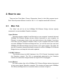
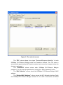
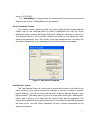
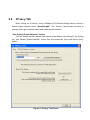
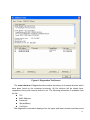
Powerline Network
Instant Network for Internet Access…and More!
Solution for SOHO, SMALL OFFICE AND HOME OFFICE
Utility Program User Guide
for
200Mbps PLC-ETHERNET BRIDGE
1
Index
1.
Introduction........................................................................3
1.1.
1.2.
1.3.
2.
System Requirements................................................................................................................ 3
Installation................................................................................................................................. 3
Run the Utility........................................................................................................................... 4
How to use .........................................................................5
2.1.
2.2.
2.3.
Main Tab ................................................................................................................................... 5
Privacy Tab ............................................................................................................................... 9
Diagnostics Tab....................................................................................................................... 11
2.4.
About Tab ............................................................................................................................... 14
2
1. Introduction
This Utility Program enables users to find 200Mbps PLC-Ethernet Bridge devices on the
Powerline network, measures data rate performance, ensures privacy and performs
diagnostics by setting user defined secure Powerline networks.
1.1.
System Requirements
Operating System
Browser
CPU
RAM
Free Disk Space
Network Interface
1.2.
Microsoft Windows 2000 , XP , Vista
Microsoft Internet Explorer 5.0 or later.
Intel Pentium III or better, clock rate faster than 2.0GHz
recommended
At least 128MB
At least 20MB
At least one Fast Ethernet (100 Mbps) network card, and
Ethernet Cord
Installation
First step, you need to verify that there is no any other Powerline Utility installed on
your computer before installing this utility. If there is another utility installed, please
uninstall it and restart your computer.
Second step, please insert the Utility CD-ROM into the computer’s CD-ROM drive.
The CD will launch a IE browser for installation as shown in Figure 1. Click the necessary
link to start installation. If IE browser is not your default browser, please run the
setup.exe at D:\Software\PLC_x86Setup\ (for 32-bit OS) or D:\Software\PLC_x64Setup\
(for 64-bit OS). (Please change D: to your CD-ROM drive).
Follow the steps to install the Utility Program. No password or CD-Key is needed.
3
Figure 1: Installation Browser Snapshot
1.3.
Run the Utility
After installing the Utility Program, please run the Utility Program from the Start / All
Programs or double-click the utility icon on the desktop. Figure 2 is the main tab screen of
the utility program. This screen shows a 200Mbps PLC-Ethernet Bridge device connected
as a local device and another 200Mbps PLC-Ethernet Bridge device as remote devices.
4
2. How to use
There are four Tabs (Main, Privacy, Diagnostics, About) in the Utility program layout.
Each Tab will provide different functions. Sec. 2.1~2.4 explains each tab’s functions:
2.1.
Main Tab
The “Main” tab will list all the 200Mbps PLC-Ethernet Bridge devices logically
connected in current available Powerline networks.
Upper Window
The upper window, entitled “Local Device(s) on your computer”, shows all the local
200Mbps PLC-Ethernet Bridge devices directly connected to your computer via
Ethernet. In most cases, there is only one device shown in the window. If you have
more than one NIC (Network Interface Card) on your computer and each of them
connects 200Mbps PLC-Ethernet Bridge devices, you will find more than one local
200Mbps PLC-Ethernet Bridge devices shown in the upper window. The Utility will
scan the Powerline network periodically to search for all the 200Mbps PLC-Ethernet
Bridge devices, and keep the information updated.
CCo MAC Address
This window shows the MAC Address of the “CCo”(Central Coordinator) inside
this Powerline network. The CCo is automatically appointed by the Powerline
network and cannot be changed unless the original CCo is unplugged.
Lower Window
The lower window lists all the 200Mbps PLC-Ethernet Bridge devices discovered
in the current logical Powerline networks. This window will report each 200Mbps
PLC-Ethernet Bridge device’s connection status, as shown in Figure 2:
5
Figure 2: The main tab screen
The “TEI” column shows the unique “Terminal Equipment Identifier” of each
200Mbps PLC-Ethernet Bridge inside the Powerline network. This TEI value is
automatically appointed by the Powerline network and cannot be changed unless the
device is unplugged.
The “Password” column shows each 200Mbps PLC-Ethernet Bridge‘s
password. You can input the password by clicking the “Enter Password” button.
The “MAC Address” column shows the 200Mbps PLC-Ethernet Bridge’s MAC
address.
The “Bridged MAC Address” column shows the NIC (Network Interface Card)
this 200Mbps PLC-Ethernet Bridge connects to. If no NIC is connected, its default
6
value is “ff:ff:ff:ff:ff:ff”.
The “Speed(Mbps)” column shows the remote device’s mutual transmit speed
with the local device, in Mbps(Million bits per second).
“Enter Password” button
If you want to create a private network, you need to enter the device password first.
Please click on the intended device to make it highlighted then click the “Enter
Password” button, and the “Set Device Password” dialog box will show up (Figure 3).
The selected device’s TEI and MAC address are shown in the dialog box. After
entering the password, click “OK” button. If the input password does not match the
device’s real password, error message will be shown and please retry again.
Figure 3: Set Device Password
“Add Remote” button
The “Add Remote” button is used to add a remote device which is not listed in the
lower window to your logical network (for example, a device is currently in another
logical network). You can click the “Add Remote” button to add the device to your
logical network. The dialog box in Figure 4 is shown after clicking the “Add Remote”
button, and it allows you to enter both the device name and the password. The
device will be added to your logical network only if the Network and DAK passwords
are both correct. Like the “Enter Password” function, incorrect passwords will be
warned and denied.
7
Figure 4: Add Remote Device
“Scan” button
The “Scan” button is used to search for the 200Mbps PLC-Ethernet Bridge devices
connected to your logical network immediately. By default setting, It will automatically
scan every 10 seconds and updates the display lists.
8
2.2.
Privacy Tab
When rolling out of factory, every 200Mbps PLC-Ethernet Bridge device carries a
default logical network name: “HomePlugAV”. The “Privacy” tab provides functions to
manage this logical network name and create private network.
“Use Default (Public Network)” button
You can directly set the network name back to the default “HomePlugAV” by clicking
the “Use Default (Public Network)” button first, then press the “Set Local Device Only”
button.
Figure 5: Privacy Tab Screen
9
“Set Local Device Only” button
The “Set Local Device Only” button is used to change the network name of the
local device only. After changing the network name to a new one, all the devices existing
in the same network before will no longer be able to communicate or respond to you,
because they will not have the same network name with the local device.
“Set All Devices” button
The “Set All Devices” button is used to change the whole logical network’s devices,
both local and remote, that showed in the Main Tab. Please fill in each remote device’s
password in advance following the instructions in Sec 2.1 (“Enter Password” button) so
that this function can proceed normally.
10
2.3.
Diagnostics Tab
The “Diagnostics” tab shows the system information and the history of all the devices
that have been found before (Figure 6).
The upper window of Diagnostics tab shows the host computer’s system data and it
shows:
MAC Address of all NICs (network interface card)
MAC Address and the firmware version of the 200Mbps PLC-Ethernet Bridge
device which is connected to each NIC
Computer name
User name
Processor and operating system information
Utility program version
Versions of all the driver DLLs and libraries used
11
Figure 6: Diagnostics Tab Screen
The lower window of Diagnostics tab contains the history of all remote devices which
have been found by the computer previously. All the devices will be shown here,
regardless of they are currently active or not. The following information is available from
the list:
TEI
MAC Address
Password
Speed(Mbps)
Last Seen
The diagnostics information displayed on the upper and lower window could be saved
12
to text file or print out by printers. Devices which no longer existed in the network can be
deleted using the “Delete...” button.
“Delete…” button
Select the device which is no longer existed in the network by clicking its record first,
then click this button to delete the record.
“View Report…” button
Click this button to view all the device information displayed on the upper and lower
window by the default text editor.
“Save Report…” button
Click this button to save all the device information displayed on the upper and lower
window to a text file directly.
“Print Report…” button
Click on this button to print the all diagnostics information to your default printer
directly.
13
2.4.
About Tab
The “About” Tab shows the software version, and manufacturer information.
14