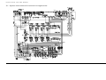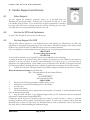
1
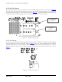
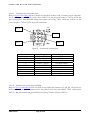
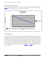
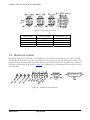
TRANSISTOR DEVICES, INC
UltraFLEX HD User Manual
708401 Rev B
U L T R A F L E X
H D
P D U
U S E R
M A N U A L
ULTRAFLEX HD PDU
User Manual
Rev B
© Transistor Devices, Inc
36 Newburgh Road
Hackettstown, NJ 07840
Phone 908-979-0088 • Fax 908-979-0466
708401 Rev B
Page 2 of 38
U L T R A F L E X
H D
P D U
U S E R
M A N U A L
Table of Contents
List of Figures ......................................................................................................................................... 5
List of Tables........................................................................................................................................... 6
List of Graphs ......................................................................................................................................... 6
1.0
System Overview .......................................................................................................................... 7
1.1
AC Input Warnings....................................................................................................................... 8
1.2
AC Input Ratings .......................................................................................................................... 8
1.3
Mounting Equipment .................................................................................................................... 9
1.3.1
Introduction............................................................................................................................. 9
1.3.2
Weight ..................................................................................................................................... 9
1.4
AC Input ....................................................................................................................................... 9
1.5
AC Outputs ................................................................................................................................... 9
1.6
DC Connections ......................................................................................................................... 11
1.6.1
Fans....................................................................................................................................... 11
1.7
EMO Loop .................................................................................................................................. 12
1.8
SMC Connection J72.................................................................................................................. 12
1.9
External Indicators Connection J71 .......................................................................................... 13
2.0
System Start-up........................................................................................................................... 14
2.1
System turn-on............................................................................................................................ 14
2.1.1
EMO breaker CB2 ................................................................................................................ 14
2.1.2
Energize AC input ................................................................................................................. 14
2.1.3
Input breaker CB1................................................................................................................. 15
2.1.4
AC Loads............................................................................................................................... 15
2.1.5
Fan breaker CB10................................................................................................................. 16
2.1.6
48V Power Supply AC input breaker CB9............................................................................ 16
2.1.7
48V DC bus turn-on .............................................................................................................. 17
2.2
System Functionality .................................................................................................................. 17
3.0
User Manual............................................................................................................................... 18
3.1
System Overview ........................................................................................................................ 18
3.2
AC Input ..................................................................................................................................... 19
3.2.1
Voltage .................................................................................................................................. 19
708401 Rev B
Page 3 of 38
U L T R A F L E X
3.2.2
H D
P D U
U S E R
M A N U A L
Frequency ............................................................................................................................. 19
3.3
EMO supply................................................................................................................................ 19
3.4
AC Input breaker........................................................................................................................ 19
3.4.1
3.5
Lock Out Feature .................................................................................................................. 19
AC Distribution .......................................................................................................................... 20
3.5.1
AC connectors....................................................................................................................... 20
3.5.2
AC outlet J52/J53.................................................................................................................. 21
3.5.3
J59 Pinout ............................................................................................................................. 21
3.5.4
Internal AC wiring ................................................................................................................ 21
3.6
Grounding .................................................................................................................................. 22
3.6.1
PDU Facility Ground Connection ........................................................................................ 22
3.6.2
PDU Frame ground .............................................................................................................. 22
3.6.3
DC Grounding ...................................................................................................................... 22
3.7
DC Distribution.......................................................................................................................... 22
3.7.1
DC Ratings............................................................................................................................ 22
3.7.2
48V DC Output ..................................................................................................................... 23
3.7.3 Fan Power............................................................................................................................. 23
3.7.3.1 Testhead Fan connector J46............................................................................................ 24
3.7.3.2 Cabinet Fan connectors J47/J48..................................................................................... 24
3.7.3.3 Expansion Cabinet power connector J49........................................................................ 25
3.7.4
48V DC Output Voltage ........................................................................................................ 26
3.8
EMO loop ................................................................................................................................... 26
3.9
Monitor & Control ..................................................................................................................... 27
3.9.1 SMC Interface J72 ................................................................................................................ 28
3.9.1.1 48V DC Enable................................................................................................................ 28
3.9.1.2 48V DC Power Fault ....................................................................................................... 29
3.9.1.3 DC current monitor ......................................................................................................... 29
3.9.2 LED Indicators & Alarm outputs.......................................................................................... 30
3.9.2.1 Alarm output connector J71 ............................................................................................ 30
3.9.2.2 AC Available.................................................................................................................... 31
3.9.2.3 Main Power On ............................................................................................................... 31
3.9.2.4 48V DC on ....................................................................................................................... 31
3.9.2.5 Power Supply LED’s ....................................................................................................... 31
3.9.3
Test Points............................................................................................................................. 31
3.9.4
Thermostat ............................................................................................................................ 31
4.0
System Ratings Summary ........................................................................................................... 33
708401 Rev B
Page 4 of 38
U L T R A F L E X
H D
P D U
U S E R
M A N U A L
4.1
AC Input ..................................................................................................................................... 33
4.2
AC Distribution .......................................................................................................................... 33
4.3
DC Distribution.......................................................................................................................... 33
4.4
Mechanical Ratings.................................................................................................................... 34
4.5
Environmental Ratings............................................................................................................... 34
5.1
System Interconnect for revision A or higher units.................................................................... 35
5.2
System Interconnect for revisions prior to revision A................................................................ 36
6
Vendor Support and Service ......................................................................................................... 37
6.1
Sales Support .......................................................................................................................... 37
6.2
Service for GFS and Customers ........................................................................................ 37
6.3
Service Support for GCS...................................................................................................... 37
7
7.1
Revision History............................................................................................................................ 38
Document updates ...................................................................................................................... 38
List of Figures
Figure 1– Front view of PDU................................................................................................................................................................................................ 7
Figure 2 – Rear view of PDU................................................................................................................................................................................................. 8
Figure 3 – AC distribution on PDU.................................................................................................................................................................................... 10
Figure 4 – DC fan connector detail..................................................................................................................................................................................... 11
Figure 5 – EMO loop connector detail .............................................................................................................................................................................. 12
Figure 6 – SMC connector detail......................................................................................................................................................................................... 12
Figure 7 – Detail of EMO breaker CB2 (shown in OFF position) ...............................................................................................................................14
Figure 8 – Detail of input breaker CB1 .............................................................................................................................................................................. 15
Figure 9 – Detail of AC load breakers CB3 – CB8 .......................................................................................................................................................... 15
Figure 10 – Detail of Fan breaker CB10 ............................................................................................................................................................................ 16
Figure 11 – Detail of Power supply AC input breaker CB9 ........................................................................................................................................... 16
Figure 12 – Overall front view of PDU ............................................................................................................................................................................. 18
Figure 13 – AC breaker lockout........................................................................................................................................................................................... 19
Figure 14 – Detail view of AC distribution........................................................................................................................................................................ 20
Figure 15 – Detail view of J59 ............................................................................................................................................................................................. 21
Figure 16 – 48V DC output bus bars.................................................................................................................................................................................. 23
Figure 17 – Fan power connectors...................................................................................................................................................................................... 23
Figure 18 – Testhead fan connector J46 ............................................................................................................................................................................ 24
Figure 19 – Cabinet fan connectors J47/J48 ..................................................................................................................................................................... 25
Figure 20 – Expansion cabinet power connector J49 ...................................................................................................................................................... 25
Figure 21 – EMO loop connectors ..................................................................................................................................................................................... 27
Figure 22 – Interface PCB connections ............................................................................................................................................................................. 27
Figure 23 – Alarm output (typical for all alarms).............................................................................................................................................................. 30
Figure 24 – Thermostat location on interface PCB.......................................................................................................................................................... 32
708401 Rev B
Page 5 of 38
U L T R A F L E X
H D
P D U
U S E R
M A N U A L
List of Tables
Table 1 – AC Output table ..................................................................................................................................................................................................... 9
Table 2 – DC Fan connection table .................................................................................................................................................................................... 11
Table 3 – SMC connector Pinout (J72) .............................................................................................................................................................................. 13
Table 4 – J72 Pinout .............................................................................................................................................................................................................. 13
Table 5 – AC Distribution details........................................................................................................................................................................................ 20
Table 6 – J59 Pinout .............................................................................................................................................................................................................. 21
Table 7 – Internal AC Distribution..................................................................................................................................................................................... 21
Table 8 – DC Output Ratings .............................................................................................................................................................................................. 22
Table 9 – J46 Pinout .............................................................................................................................................................................................................. 24
Table 10 – J47/J48 Pinout.................................................................................................................................................................................................... 25
Table 11 – J49 Pinout ............................................................................................................................................................................................................ 25
Table 12 – EMO connectors................................................................................................................................................................................................ 27
Table 13 – J72 Pinout ............................................................................................................................................................................................................ 28
Table 14 – J71 Pinout ............................................................................................................................................................................................................ 30
List of Graphs
Graph 1 – Output V vs. load graph .................................................................................................................................................................................... 26
Graph 2 – Current monitor signal vs. load graph............................................................................................................................................................. 29
708401 Rev B
Page 6 of 38
U L T R A F L E X
H D
P D U
U S E R
1.0 System Overview
Refer to Figure 1 and Figure 2 below for front and rear views of the PDU respectively.
The major components of the PDU are shown on the diagrams.
AC output breakers
on top half of front
panel: Figure 3
AC input
breaker CB1:
. Figure 8
AC input
breaker
cover:
Figure 8
AC outlets on lower
half of front panel:
Figure 3
Power Status
LED’s: Figure 7
Figure 1– Front view of PDU
708401 Rev B
Page 7 of 38
1
Chapter
M A N U A L
U L T R A F L E X
H D
P D U
U S E R
M A N U A L
Power supply access
panel.:
External indicator
connector J71:
Figure 6
SMC connector:
Figure 6
EMO connectors:
Figure 5
Test points:
Figure 22
Fan connectors J47/J48: Figure
19
Alarm & Power
Status LED’s:
Figure 22
Fan connector J46: Figure 18
Fan Breaker CB10: Figure 10
DC bus protective
cover: Figure 4
Figure 2 – Rear view of PDU
1.1 AC Input Warnings
WARNING: HIGH TOUCH CURRENT. EARTH CONNECTION ESSENTIAL
BEFORE CONNECTING SUPPLY.
AVERTISSEMENT: HAUTE TENSION DE CONTACT. LA MISE A LA TERRE
EST ESSENTIELLE AVANT DE BRANCHER L’ALIMENTATION.
1.2 AC Input Ratings
SPS5809-4
(708355-4)
708401 Rev B
System, PDU supplied with 4 rectifiers
Input: 200-208VAC, 50-60Hz, 125A Max
Output: 48Vdc, 320A Max, 15,200W Max. (4 rectifiers)
Output: 208-230VAC, 50-60Hz, 19,000W Max
Output 115VAC, 50-60Hz, 575W Max
AMBIENT: 30°C Max.
Page 8 of 38
U L T R A F L E X
H D
P D U
U S E R
M A N U A L
1.3 Mounting Equipment
1.3.1 Introduction
The PDU was specifically designed for installation into the Teradyne cabinet. Since there are no mechanical
mounting features on the PDU, it must be installed in a shelf within the Teradyne cabinet. Mounting of the
PDU to the shelf to be specified by Teradyne. Refer to Teradyne service documentation for installation of
PDU into the UltraFLEX HD system.
1.3.2 Weight
The weight of the PDU is approximately 125 Lbs. Do not attempt to lift the PDU without assistance or use of
mechanical lift.
1.4 AC Input
The AC input required is a separately protected 200/208 VAC three phase input with a dedicated ground wire.
The AC input can be configured as a 3 Phase Delta (with or without one leg grounded) or a 3 Phase Wye
(Neutral not used). The AC feed must be capable of supplying a continuous current of 150A. The frequency
range for the input is 47-63 Hz. All AC wiring should be performed by a licensed electrician and in accordance
with local and regional electrical codes. Before starting any cabling, verify the AC feed breaker CB1 is turned
off and follow the facility LOTO (Lock Out Tag Out) procedure.
1.5 AC Outputs
All AC connections are located on the front of the PDU next to the AC input circuit breaker. Refer to Table 1
and Figure 3 for descriptions of the connections.
Use
Expansion Cabinet Vault
DC-PM
CDU
SMC
Spare
Manipulator
Spare
External IEC Spare
External IEC Spare
External IEC (CPU & Monitor)
External IEC (DSP)
708401 Rev B
Outlet Number Circuit Breaker
J58
CB4
J66
CB3
J59
CB5
J50
J51
CB6
J56
J57
J54
CB7
J55
J52
CB8
J53
Table 1 – AC Output table
Page 9 of 38
Breaker Rating (A)
20
30
25
15
15
5
U L T R A F L E X
H D
P D U
U S E R
M A N U A L
Figure 3 – AC distribution on PDU
708401 Rev B
Page 10 of 38
U L T R A F L E X
H D
P D U
U S E R
M A N U A L
1.6 DC Connections
All DC connections are located on the rear of the PDU. The DC connections include the 48V DC output and
fan power.
1.6.1 Fans
All fan connectors are located on the rear of the PDU as shown in Figure 4. In addition, refer to Table 2
below for descriptions of the connectors.
Use
Testhead Fans
System Cabinet Fan
Expansion Cabinet Fan
Expansion cabinet power control
Outlet Number
J46
J47
J48
J49
Circuit Breaker
Breaker Rating (A)
CB10
15
Table 2 – DC Fan connection table
Fan connectors
Fan circuit breaker
DC bus protective
cover
Figure 4 – DC fan connector detail
708401 Rev B
Page 11 of 38
U L T R A F L E X
H D
P D U
U S E R
M A N U A L
1.7 EMO Loop
The PDU contains 4 EMO loop connectors on the rear of the PDU directly to the left of the test points.
Supplied with the PDU is an EMO loop connector installed in J70. If an external power vault is used, remove
the jumper installed in J70 and connect the power vault EMO. If power vault is used, the J70 jumper must
remain installed. Refer to Figure 2 for where the EMO connectors are located and Figure 5 below for a
detailed view of the EMO connectors on the rear of the PDU.
Figure 5 – EMO loop connector detail
1.8 SMC Connection J72
The SMC connector is also located on the rear of the PDU. Refer to Figure 2 for the location of the SMC
connector and Figure 6 below for a detailed view. The pinout of the SMC connector is detailed in Table 3.
Figure 6 – SMC connector detail
708401 Rev B
Page 12 of 38
U L T R A F L E X
H D
P D U
U S E R
Pin Number
1
2
3
4
5
6
7
8
9
10
11
12
13
14
15
16
17
18
19
20
21
22
23
24
25
M A N U A L
Signal
Notes
Not-Used
Fan Speed Control 1
From J46 pin 4
PUMA ID bit
Jumper to J72 pin 4
Common
Jumper to J72 pin 3
48V current monitor
Output to SMC
48V current monitor return
Output to SMC
Not-Used
Not-Used
Not-Used
Not-Used
5V from SMC to PDU
Input from SMC
Not-Used
48V DC Enable
Input from SMC
Not-Used
Not-Used
Not-Used
Not-Used
Not-Used
48V DC power fault
Output to SMC
48V DC power fault return
Output to SMC
Not-Used
Not-Used
Not-Used
Fan Speed Control 1 return
From J46 pin 5
48V DC Enable return
Input from SMC
Table 3 – SMC connector Pinout (J72)
1.9 External Indicators Connection J71
The external indicator connector is located on the rear of the PDU next to the SMC connector; refer to Figure
2 for location of external indicator connector and Figure 6 for a detailed view. The pinout of the external
indicator connector is detailed in Table 4.
Pin Number
Signal
1
AC Available
2
Not-Used
3
Main Power On
4
48V DC On
5
Not-Used
6
AC Available return
7
Not-Used
8
Main Power On return
9
48V DC On return
Table 4 – J72 Pinout
708401 Rev B
Page 13 of 38
U L T R A F L E X
H D
P D U
U S E R
M A N U A L
2.0 System Start-up
Verify all AC and DC circuit breakers are turned off. Before applying power, it is
recommended to fully read the User Manual portion of this document to become familiar
with all the components and functions of the system. If any problems are encountered
during the start-up of the system, press one of the systems EMO switches to shut down
the system.
2
Chapter
2.1 System turn-on
2.1.1 EMO breaker CB2
Turn on EMO breaker CB2 located on the front panel of the PDU; refer to Figure 7 for actual location. To
turn on CB2, rotate the handle on the breaker up toward the top of the PDU. If the handle if down toward the
bottom (as shown in Figure 7), the breaker is off. With CB2 on, it will allow the EMO supply to turn on as
soon as the AC input is energized. Refer to Figure 7 for a view of EMO breaker CB2.
AC available,
AC ON and
48V DC
LED’s
EMO breaker
CB2
Figure 7 – Detail of EMO breaker CB2 (shown in OFF position)
2.1.2 Energize AC input
Energize the AC input to the PDU by turning on the facility circuit breaker. Once the AC input is energized,
the AC Available LED should be illuminated green, refer to Figure 7 above for the location of the AC available
LED. If the AC Available LED is not illuminated, verify the EMO breaker CB2 is on and that the AC input is
within the operating range (187 – 253 VAC).
708401 Rev B
Page 14 of 38
U L T R A F L E X
H D
P D U
U S E R
M A N U A L
2.1.3 Input breaker CB1
Once the AC is energized, the AC input breaker can be turned on. Turn on the AC input breaker CB1 located
on the front of the PDU by pushing the breaker handle upward. If the breaker handle is facing the bottom of
the PDU (as shown in Figure 8), the breaker is off. Once the input breaker is on, the Main Power On LED is
illuminated green, refer to Figure 7 for the location of the Main Power On LED. If the Main Power On LED
is not illuminated, verify all EMO loop connectors are plugged in and no EMO buttons are depressed. With an
open EMO loop, the input breaker cannot be turned on. Refer to Figure 8 for a view of input breaker CB1.
Input breaker
CB1
Figure 8 – Detail of input breaker CB1
2.1.4 AC Loads
Once the AC input breaker is on, the AC loads can be connected, refer to Figure 1 for the location of the AC
load breakers and Figure 9 for a detail view. Turn on the AC load breakers CB3, CB4, CB5, CB6, CB7 and
CB8 one at a time. Note: All breakers shown in Figure 9 are in the off position.
Figure 9 – Detail of AC load breakers CB3 – CB8
708401 Rev B
Page 15 of 38
U L T R A F L E X
H D
P D U
U S E R
M A N U A L
2.1.5 Fan breaker CB10
Turn on fan breaker CB10 located on the rear of the PDU, refer to Figure 2. Without this breaker turned on,
the cabinet fans cannot power up. Refer to Figure 10 for a view of CB10. Note: Breaker CB10 shown below
is in the off position.
Fan breaker
CB10
Figure 10 – Detail of Fan breaker CB10
2.1.6 48V Power Supply AC input breaker CB9
Turn the power supply AC input breaker CB9 located on the front panel of the PDU, refer to Figure 1. Once
the breaker is turned on the AC input will be fed into the power supplies. Although the DC output of the
power supplies will be off, you may hear a “clicking” noise. This noise is normal and is a result of the
magnetics in the supplies operating in a no-load condition. Refer to Figure 11 for a view of CB9. Note: Breaker
CB9 shown below is in the off position.
Power supply AC
input breaker
CB9
Figure 11 – Detail of Power supply AC input breaker CB9
708401 Rev B
Page 16 of 38
U L T R A F L E X
H D
P D U
U S E R
M A N U A L
2.1.7 48V DC bus turn-on
After all breakers have been turned on, the 48V DC bus can be enabled via the SMC controller. Once the 48V
DC output is energized, the 48V On LED will be illuminated green. If the 48V does not turn on verify the
power supply AC input breaker CB9 is turned on and power supplies are installed. Refer to Service Manual for
troubleshooting.
2.2 System Functionality
Once the PDU is operational it is ready for system testing. If any portion of the system is found to be non
functional or there are active alarms, refer to the Troubleshooting section in the Service Manual for assistance.
708401 Rev B
Page 17 of 38
U L T R A F L E X
H D
P D U
U S E R
M A N U A L
3.0 User Manual
This section provides an overview of the PDU system functionality. Also detailed in this
section are the system specifications, connector designations and connector pinouts.
3.1 System Overview
3
Chapter
The PDU is designed to provide overcurrent protected AC distribution and a 48V DC output. The 48V DC
output is derived from modular power supplies. The only cooling within the PDU are the fans on the
individual power supply modules. Other features of the PDU include alarm indications, EMO shutdown
feature, test points for troubleshooting and connections for the SMC controller. Refer to Figure 12 for an
overall view of the PDU.
Figure 12 – Overall front view of PDU
708401 Rev B
Page 18 of 38
U L T R A F L E X
H D
P D U
U S E R
M A N U A L
3.2 AC Input
The AC input to the PDU can be configured as a 3 Phase Delta (with or without one leg grounded) or a 3
Phase Wye (Neutral not used). The AC feed must be capable of supplying a continuous current of 150A.
Voltage and frequency ratings are specified below.
3.2.1 Voltage
Power Supply operating voltage range is 187 – 253 VAC.
AC input operating range is 200/208 VAC.
3.2.2 Frequency
Frequency range is 47 – 63 Hz.
3.3 EMO supply
The PDU contains a 24V EMO supply that is wired directly to the AC input (before AC input breaker CB1).
This allows the EMO supply to be on as soon as the AC to the PDU is energized. The EMO supply is
protected by a 3A breaker (CB2) on the front panel of the PDU. The EMO supply is used to power the
interface PCB as well as the UVR (under voltage release) on the input circuit breaker CB1.
3.4 AC Input breaker
The AC input breaker is a three-phase 150A thermal magnetic circuit breaker and contains a UVR (under
voltage release). The UVR will not allow the breaker to be turned on unless 24V from the EMO supply is
provided to the breaker through the EMO loop. Conversely, the breaker will trip if the supplied 24V to the
breaker drops below 16 volts or the EMO loop is opened.
3.4.1 Lock Out Feature
The AC breaker can be locked in the off position by installing a padlock through the hole in the lockout
bracket. This will prevent anyone from turning on the PDU. Refer to Figure 13 for a view of a lock installed.
Lockout bracket
Breaker handle
Figure 13 – AC breaker lockout
708401 Rev B
Page 19 of 38
U L T R A F L E X
H D
P D U
U S E R
M A N U A L
3.5 AC Distribution
All the AC distribution is provided on the front panel of the PDU. Refer to Figure 14 for a detailed view of the
AC distribution. The AC loads are distributed as evenly as possible across the three phases. The system wiring
is optimized for the least current phase imbalance for the system. For more detailed information on the AC
distribution refer to the System Interconnect drawing.
Figure 14 – Detail view of AC distribution
3.5.1 AC connectors
Table 5 below details the specifications on the AC distribution connectors.
Outlet
Number
External IEC
J52
External IEC (DSP)
J53
External IEC Spare
J54
External IEC Spare
J55
SMC
J50
Spare
J51
Manipulator
J56
Spare
J57
Expansion Cabinet Vault J58
CDU
J59
DC-PM
J66
Use
708401 Rev B
Circuit Breaker
# phases
Breaker Rating (A)
Used
Phases
Voltage
(VAC)
CB8
5
2
B&C
115
CB7
15
2
B&C
208-230
CB6
15
2
A&B
208-230
CB4
20
3
A, B & C 208-230
CB5
25
3
A, B & C 208-230
CB3
30
3
A, B & C 208-230
Table 5 – AC Distribution details
Page 20 of 38
Connector type
5-15R
5-15R
6-15R
6-15R
60320-C20
60320-C20
6-15R
6-15R
L15-20R
Amp mate-n-lok
L15-30R
U L T R A F L E X
H D
P D U
U S E R
M A N U A L
3.5.2 AC outlet J52/J53
As shown in Table 5 above, the output of AC outlet J52/J53 is 115VAC. This output is provided through a
step-down transformer within the PDU. Refer to install section 1.1.2 in the service manual for proper
configuration for this AC output.
3.5.3 J59 Pinout
Refer to Figure 15 and Table 6 below for details on CDU connector J59: Connector used is Amp Mate-N-Lok
series, part number 770027-1 with sockets 193797-1 and key plugs 770377-1. Recommended mating part
numbers are housing 770020-1 with pins 193796-1.
Pin 1
Pin 3
Pin 6
Pin 4
Figure 15 – Detail view of J59
Pin Number
1
2
3
4
5
6
Pin type
Plug 770377-1
Plug 770377-1
Socket 193797-1
Socket 193797-1
Socket 193797-1
Socket 193797-1
Description
Key plug
Key plug
Ground
Phase A
Phase B
Phase C
Table 6 – J59 Pinout
3.5.4 Internal AC wiring
Internal AC wiring is required for the AC feed to the EMO supply as well as the power supplies. Refer to
Table 7 for details on the input AC wiring.
Circuit Breaker
# phases
Breaker Rating (A)
EMO supply
CB2
3
2
Power supply 1
2
Power supply 2
2
CB9
80
Power supply 3
2
Power supply 4
2
Table 7 – Internal AC Distribution
Use
708401 Rev B
Page 21 of 38
Used
Phases
A&B
A&B
B&C
A&C
A&C
U L T R A F L E X
H D
P D U
U S E R
M A N U A L
3.6 Grounding
3.6.1 PDU Facility Ground Connection
The main AC input ground is located close to the input circuit breaker CB1. Refer to section 1.1.4 in the
service manual for details on connections to the AC ground.
3.6.2 PDU Frame ground
A frame ground connection is provided on the PDU near the main AC input. Refer to section 1.1.5 in the
service manual for details on connecting the frame ground.
3.6.3 DC Grounding
The 48V DC return is connected to chassis ground within the PDU. The connection is made between the
power supply output and chassis on the power supply backplane (PCB the power supplies plug into).
3.7 DC Distribution
The PDU provides a main 48V DC output as well as a 48V output for system fans. The 48V power supplies in
the PDU receive AC as soon as the main AC breaker (CB1) and power supply AC input breaker (CB9) are
turned on. The 48V output is inhibited (off) until commanded to turn on by the SMC controller. The 48V
output is inhibited (off) even if SMC is not present or is disconnected. While the power supplies are inhibited,
you may hear a “clicking” noise. This noise is normal and is a result of the magnetics in the power supply
operating in a no-load condition.
3.7.1 DC Ratings
Refer to Table 8 below for the DC output ratings of the PDU. Refer to Fan Power section 3.7.3 below for
pinout details on the fan power connectors.
DC Output
Output connector
Max Current
Main 48V Output
Bus bars
300 A
Testhead Fans
Cabinet Fan
Expansion cabinet fan
Expansion cabinet power
708401 Rev B
7.5 A (running)
9.5 A (locked rotor)
1.75 A (running)
J47
2.25 A (locked rotor)
1.75 A (running)
J48
2.25 A (locked rotor)
J49
Table 8 – DC Output Ratings
J46
Page 22 of 38
Max Power
14,400 W
360 W
456 W
84 W
108 W
84W
108 W
15 W
U L T R A F L E X
H D
P D U
U S E R
M A N U A L
3.7.2 48V DC Output
The main 48V output bus bars are located on the rear of the PDU under a protective cover. Refer to Figure 16
for a view of the DC output bus bars with the cover removed. The 48V output bus (positive) is on the top and
the 48V return bus (negative) is on the bottom as shown in Figure 16. To prevent incorrect connections to the
bus bars, the center-to-center spacing is 1.0” on the output bus and 1.375” on the return bus.
48V Output bus
(positive)
48V Return bus
(negative)
Figure 16 – 48V DC output bus bars
3.7.3 Fan Power
Connectors for the Test Head Fantray, system cabinet fan, expansion cabinet fan and expansion cabinet power
vault are provided on the rear of the PDU. Refer to Figure 17 for a view of fan connectors J46, J47, J48 and
expansion cabinet power vault connector J49. Pinout details for each connector are provided below. Power to
the fan connectors is protected by a 15A circuit breaker CB10 located below the fan connectors as shown in
Figure 17.
Figure 17 – Fan power connectors
708401 Rev B
Page 23 of 38
U L T R A F L E X
3.7.3.1
H D
P D U
U S E R
M A N U A L
Testhead Fan connector J46
Refer to Figure 18 and Table 9 below for details on testhead fan connector J46: Connector used is Amp MateN-Lok series, part number 770028-1 with sockets 194213-1 for fan power and sockets 1-770253-0 for the fan
speed control wires. Recommended mating part numbers are housing 770021-1 with pins 194212-1 for fan
power and pins 1-770252-0 for the fan speed control wires.
Pin 1
Pin 4
Pin 3
Pin 5
Figure 18 – Testhead fan connector J46
Pin Number
1
2
3
4
5
6
7
8
9
3.7.3.2
Pin type
Description
Socket 194213-1
+48V DC output
Socket 194213-1
+48V DC return
Socket 194213-1
Chassis Ground
Socket 1-770253-0
Fan speed control 1
Socket 1-770253-0
Fan speed control 1 return
No contact
No contact
No contact
No contact
Table 9 – J46 Pinout
Cabinet Fan connectors J47/J48
Refer to Figure 19 and Table 10 below for details on the cabinet fan connectors J47 and J48. The pinout for
both connectors is identical. Connector used is Amp Mate-N-Lok series, part number 770025-1 with sockets
194213-1. Recommended mating part numbers are housing 770018-1 with pins 194212-1.
708401 Rev B
Page 24 of 38
U L T R A F L E X
H D
P D U
U S E R
M A N U A L
Pin 1
Pin 3
Figure 19 – Cabinet fan connectors J47/J48
Pin Number
1
2
3
3.7.3.3
Pin type
Socket 194213-1
Socket 194213-1
Table 10 – J47/J48 Pinout
Description
+48V DC output
+48V DC return
No contact
Expansion Cabinet power connector J49
Refer to Figure 20 and Table 11 below for details on the expansion cabinet power connector J49. Connector
used is Amp Mate-N-Lok series, part number 770025-1 with pins 194212-1. Recommended mating part
numbers are housing 770018-1 with sockets 194213-1.
Pin 1
Pin 3
Figure 20 – Expansion cabinet power connector J49
Pin Number
1
2
3
708401 Rev B
Pin type
Pin 194212-1
Pin 194212-1
Table 11 – J49 Pinout
Page 25 of 38
Description
No contact
+48V DC return
+48V DC output
U L T R A F L E X
H D
P D U
U S E R
M A N U A L
3.7.4 48V DC Output Voltage
The output voltage will vary slightly with load. The output voltage of the PDU is 48V @ full load. Refer to
Graph 1 below for the output voltage at various loads. The output voltage range over entire load range is
48.5V +/- 0.5V. External adjustments of the 48V output are not available.
DC Output Voltage
(4 Rectifiers)
49.2
49.0
DC Output Voltage
48.8
48.6
48.4
DC Output V
48.2
48.0
47.8
47.6
47.4
0
25
50
75
100 125 150 175 200 225 250 275 300
DC Output V 49.0 49.0 48.9 48.7 48.6 48.5 48.4 48.3 48.2 48.1 48.0 48.0 48.0
DC load
Graph 1 – Output V vs. load graph
3.8 EMO loop
The PDU contains an EMO loop which will shut down the PDU if the loop is broken. When the EMO loop
is broken CB1 is opened. The EMO supply still remains powered up. The EMO connectors on the PDU are
J67, J68, J69 and J70 and are located on the rear of the PDU. A jumper is provided in J70 on all PDU’s since
an external power vault is not always used. When the EMO loop is broken, the 24V EMO voltage to the UVR
on the input breaker is lost resulting in the circuit breaker tripping which shuts down the PDU. The EMO
loop connectors used for J67, J68 and J69 are housing 770024-1 with sockets 1-770008-0. Recommended
mating connector for J67, J68 and J69 is housing 770017-1 with pins 1-770007-0. The EMO loop connector
used for J70 is housing 770027-1 with sockets 1-770008-0 and1-770006-0. Recommended mating connector
for J70 is housing 770020-1 with pins 1-770007-0. Refer to Figure 21 and Table 12 below for details on the
EMO connectors.
708401 Rev B
Page 26 of 38
U L T R A F L E X
H D
P D U
U S E R
M A N U A L
Figure 21 – EMO loop connectors
EMO location
Test head
Support Cabinet
Chiller
External Power Vault
Connector number
Supplied with PDU
J67
No
J68
No
J69
No
J70
Yes
Table 12 – EMO connectors
3.9 Monitor & Control
Monitoring and control of the PDU is accomplished via the interface PCB mounted at the rear of the PDU.
The interface PCB contains test points, alarm LED’s and connections for external alarms and the SMC. The
interface PCB also contains a filter for the 48V DC fan output and connections for the EMO loop. See below
for details on the interface PCB. Refer to Figure 22 for a detailed view of the interface PCB connections on the
rear of the PDU.
Figure 22 – Interface PCB connections
708401 Rev B
Page 27 of 38
U L T R A F L E X
H D
P D U
U S E R
M A N U A L
3.9.1 SMC Interface J72
The SMC interface connector is J72 on the PDU and is a 25-pin D-sub connector. The pinout is detailed in
Table 13 below. Details provided below for the 48V current monitor, 48V DC enable, and 48V DC power
fault signals.
Pin Number
1
2
3
4
5
6
7
8
9
10
11
12
13
14
15
16
17
18
19
20
21
22
23
24
25
3.9.1.1
Signal
Not-Used
Fan Speed Control 1
PUMA ID bit
Common
48V current monitor
48V current monitor return
Not-Used
Not-Used
Not-Used
Not-Used
5V from SMC to PDU
Not-Used
48V DC Enable
Not-Used
Not-Used
Not-Used
Not-Used
Not-Used
48V DC power fault
48V DC power fault return
Not-Used
Not-Used
Not-Used
Fan Speed Control 1 return
48V DC Enable return
Table 13 – J72 Pinout
Notes
From J46 pin 4
Jumper to J72 pin 4
Jumper to J72 pin 3
Output to SMC
Output to SMC
Input from SMC
Input from SMC
Output to SMC
Output to SMC
From J46 pin 5
Input from SMC
48V DC Enable
The 48V DC enable is a signal from the SMC to enable the 48V DC output. With no connections to J72, the
48V DC output will be off. To enable the 48V DC output, a 5V signal must be applied between pin 13
(positive) and pin 25 (negative) on J72. The 5V signal drives the diode side of an optocoupler to enable the
48V DC output. The 48V DC enable must be capable of providing a minimum current of 12mA to enable the
power supplies.
708401 Rev B
Page 28 of 38
U L T R A F L E X
3.9.1.2
H D
P D U
U S E R
M A N U A L
48V DC Power Fault
The 48V DC power fault is a common fault signal for all the 48V power supplies installed in the system. The
fault signals of all the power supplies are tied together so any single fault will generate a 48V DC power fault
signal. The 48V DC power fault will also be generated when no rectifiers are installed. Rectifier good LED’s
are provided for visual indication of a failed power supply. The 48V DC power fault output is the transistor
side of an optocoupler. Maximum recommended current draw through the optocoupler is 3mA. A 48V DC
power fault will be active when the 48V bus is disabled or when any of the power supplies have failed.
3.9.1.3
DC current monitor
The interface PCB provides a DC current monitor signal to the SMC controller. The current monitor signal is
designed to produce 2.7V across a 158 Ohm resistor with a load of 300A. Refer to Graph 2 below showing the
DC current monitor signal for various load conditions.
Current Monitor Signal (4 rectifiers installed)
3
Current Monitor (V)
2.5
2
1.5
I mon
1
0.5
0
0
25
50
75
100 125 150 175 200 225 250 275 300
DC Load (A)
Graph 2 – Current monitor signal vs. load graph
708401 Rev B
Page 29 of 38
U L T R A F L E X
H D
P D U
U S E R
M A N U A L
3.9.2 LED Indicators & Alarm outputs
LED indicators are provided on the interface PCB for AC available, Main power on, 48V DC on, and power
supply status. LED’s for AC available, Main power on and 48V DC on are also provided on the front of the
PDU. Alarm outputs are also provided for AC available, Main power on and 48V DC on connector J71. Refer
to Figure 22 for a view of the LED indicators and alarm output connector J71 on the rear of the PDU.
3.9.2.1
Alarm output connector J71
The alarm output connector is J71 and is a 9-pin D-sub connector. These alarm outputs can be used for
external LED’s. Refer to Table 14 below for the pinout on J71. The alarm outputs are open collectors as
shown in Figure 23. Logic level for all alarms is TTL high = Normal, TTL low = Fault. The maximum
recommended current through the transistor is 50mA.
Pin Number
Signal
1
AC Available
2
Not-Used
3
Main Power On
4
48V DC On
5
Not-Used
6
AC Available return
7
Not-Used
8
Main Power On return
9
48V DC On return
Table 14 – J71 Pinout
Figure 23 – Alarm output (typical for all alarms)
708401 Rev B
Page 30 of 38
U L T R A F L E X
3.9.2.2
H D
P D U
U S E R
M A N U A L
AC Available
The AC available signal monitors phases B & C of the AC from the input side of circuit breaker CB1. The AC
available LED’s will be illuminated green provided that both EMO breaker CB2 is on and the AC voltage is
above 170 VAC.
WARNING: IF EMO BREAKER IS OFF, THERE WILL BE NO INDICATION
AC IS PRESENT WITHIN THE PDU. WHENEVER WORKING ON THE PDU
ALWAYS FOLLOW LOCK OUT TAG OUT PROCEDURES AND MEASURE
FOR VOLTAGES BEFORE PERFORMING ANY WORK.
3.9.2.3
Main Power On
The Main power on signal monitors phases B & C of the AC on the output side of circuit breaker CB1. The
Main power on LED will be illuminated green provided that both input breaker CB1 is on and the AC voltage
is above 170 VAC.
3.9.2.4
48V DC on
The 48V DC on signal monitors the 48V DC output. The 48V DC on LED will be illuminated green
whenever the 48V DC output voltage is above 44 VDC.
3.9.2.5
Power Supply LED’s
The interface PCB contains LED’s to show the status of the power supplies. When the 48V DC bus is
enabled, all installed power supplies should have their corresponding LED illuminated green. If a power supply
is not installed or failed, the corresponding LED will be off. All power supply LED’s will be off when the 48V
bus is inhibited (off). Refer to Figure 22 for a view of the rectifier good LED’s.
3.9.3 Test Points
Test points are provided on the interface PCB as shown in Figure 22. There is one set of test points for the
24V EMO supply output and one set for the 48V DC output. The test points are protected against short
circuit by re-settable fuses. For all test points, red is positive and black is negative.
3.9.4 Thermostat
A normally closed thermostat is located on the interface PCB which will shut down the PDU due to extreme
temperatures. The thermostat is rated 45°C +/- 5°C and is installed in the positive leg of the 24V EMO power
to the EMO loop. If the temperature reaches the thermostat set-point, the thermostat will open and trip input
breaker CB1 resulting in the shut down the PDU. The thermostat will automatically reset after the temperature
has reached about 35 degrees C, but the PDU will remain off since the input breaker will need to be turned on.
The thermostat should re-set within 1 minute as long as the temperature is 4 degrees below the trip range (trip range
is 40C - 50C). The PDU will not be able to be turned on until the thermostat has reset. As shown in Figure 24,
the thermostat is located on the interface PCB, behind the test points. To check if the thermostat is
open/closed, refer to section 2.1 (item 7) of the Service Manual.
708401 Rev B
Page 31 of 38
U L T R A F L E X
H D
P D U
U S E R
M A N U A L
Thermostat
Test Points
Figure 24 – Thermostat location on interface PCB
708401 Rev B
Page 32 of 38
U L T R A F L E X
H D
P D U
U S E R
M A N U A L
4
Chapter
4.0 System Ratings Summary
4.1 AC Input
Description
Rating
3 phase delta (3 wire plus ground) or
3 phase wye (3 wire plug gnd, neutral not used)
200/208 VAC
47 – 63 Hz
>.95
> 90%
110 A
150 A
AC input
PDU AC Input Range
AC frequency
Power Factor
System efficiency
Max AC input current (@187VAC input full load)
AC circuit breaker rating
4.2 AC Distribution
Outlet Number
J52/J53
J54/J55
J50/J51/J56/J57
J58
J59
J66
Circuit Breaker
CB8
CB7
CB6
CB4
CB5
CB3
Breaker Rating (A)
5
15
15
20
25
30
AC type
Voltage (VAC)
Single phase
115
Single phase
208-230
Single phase
208-230
Three phase
208-230
Three phase
208-230
Three phase
208-230
Frequency
47 – 63 Hz
47 – 63 Hz
47 – 63 Hz
47 – 63 Hz
47 – 63 Hz
47 – 63 Hz
4.3 DC Distribution
Output connector
Circuit Breaker
Breaker Rating (A)
Max Current
Bus bars
-
-
300 A
15 A
7.5 A (running)
9.5 A (locked rotor)
1.75 A (running)
2.25 A (locked rotor)
1.75 A (running)
2.25 A (locked rotor)
-
J46
J47
CB10
J48
J49
708401 Rev B
Page 33 of 38
U L T R A F L E X
H D
P D U
U S E R
M A N U A L
4.4 Mechanical Ratings
Description
PDU Dimensions
PDU Weight (including 4 power supplies)
Individual power supply weight
Rating
19”W x 35.5”D x 12.1”H
125 Lbs
6 Lbs
4.5 Environmental Ratings
Description
Temperature range (operating)
Temperature range (storage)
Humidity (operating)
Humidity (storage)
Ambiant Noise
708401 Rev B
Page 34 of 38
Rating
20C – 30C
-40C – 85C
30% - 70% non condensing
5% - 95% non condensing
62dBa
U L T R A F L E X
H D
P D U
U S E R
M A N U A L
5.1 System Interconnect for revision A or higher units
708401 Rev B
Page 35 of 38
5
Chapter
U L T R A F L E X
H D
P D U
U S E R
M A N U A L
5.2 System Interconnect for revisions prior to revision A
708401 Rev B
Page 36 of 38
U L T R A F L E X
H D
P D U
U S E R
M A N U A L
6 Vendor Support and Service
6.1
Sales Support
All sales support for purchases, proposals, spares, etc. is provided from our
Hackettstown, New Jersey facility. Normal hours of operation are 8:00 a.m. to 5:00
p.m. Monday through Friday. If you should have an urgent requirement for products
or services after these hours, a message may be left with our answering service at (908)
979-0088, and one of our representatives will return your call.
6.2
6
Chapter
Service for GFS and Customers
Contact 1-900-Teradyne as with any other Teradyne part.
6.3
Service Support for GCS
TDI provides 24-hour response to your technical service needs utilizing our infrastructure of offices and
representatives strategically located throughout the United States. Should an emergency arise during normal
business hours, please call (908) 979-0088 and request service or technical assistance.
If you are calling after our normal business hours, please use one of the following technical assistance numbers:
1-888-575-8875
Or when calling internationally
1-973-283-7236
Your call will be returned as soon as possible by one of our technical service technicians.
As stated previously in the General Terms and Conditions, all components of the TDI DC power plant are
warranted to be free of defects in material and workmanship for a period of two (2) years from date of
shipment to the original purchaser. In the unlikely event a component of the TDI DC power plant should fail,
the following procedures should be followed to expedite the repair and/or replacement of the failed module.
1.
Contact the authorized TDI repair facility at the address and phone number shown below to obtain a
Return Authorization Number for the failed unit.
TDI - Telecommunication Power Systems Division
RMA# ____________
36 Newburgh Road
Hackettstown, NJ 07840
(908) 979-0088
2.
Please have the following information available when you call:
•
Description of component including serial no. (If available)
•
In service date
•
Nature of the failure
3.
The TDI authorized factory representative will determine the method of return/replacement based
upon the information provided.
4.
Ship the failed unit back to the designated repair facility per the instructions from the authorized
representative, transportation charges PREPAID.
Components which fail after the warranty period has expired, or which fail due to misuse or abnormal
operating conditions, will be repaired at the purchaser's expense. In such cases, an estimate will be made and
submitted prior to repair. In cases where it is determined that no fault or malfunction exists in the returned
unit, there will be a nominal handling and verification charge.
708401 Rev B
Page 37 of 38
U L T R A F L E X
H D
P D U
U S E R
M A N U A L
7
Chapter
7 Revision History
Revision
P1
ECN #
-
P2
-
P3
-
P4
-
P5
-
P6
A
28901
Description of Change
Created Document
Updated per Teradyne mark-ups
Change to User Manual only
Updated interconnect drawing
Updated front views of PDU to
show new breaker arrangement
Updated per Teradyne review of
P2.
Change input breaker and AC input
from 125A to 150A. Added AC
line configurations. Correct typing
& table of contents field.
Change current monitor signal from
2.5V to 2.7V @ 300A. Update
Graph 2 based on data taken from
updated PDU.
Added internal links, added section
for Service Support – GFS and
customers to contact 1-800Teradyne
Update EMO loop information is
3.8, Figures 2, 5 & 21. Update
interconnect drawing for new EMO
loop. Release to rev A.
Changed AC input range to
200/208 VAC
Date
08/13/07
Change By
FQ
11/27/07
FQ
12/4/07
FQ
12/5/07
FQ
1/22/08
FQ
5/4/08
AO
5/14/08
F.Q.
Checked By
7.1 Document updates
This document is supplied to Teradyne for complete review. Teradyne can edit this document as needed to
incorporate into their system documentation. TDI will maintain the revision of this document and make
updates agreed between Teradyne and TDI when questions arise about the content or lack thereof.
708401 Rev B
Page 38 of 38
Filename:
Directory:
Template:
Title: Manual
Subject:
Author:
Keywords:
Comments:
Creation Date:
Change Number:
Last Saved On:
Last Saved By:
Total Editing Time:
Last Printed On:
As of Last Complete Printing
Number of Pages:
Number of Words:
Number of Characters:
708401Rev B UltraFLEX HD PDU User Manual.doc
C:\Documents and Settings\naponem\Desktop\Power
C:\WINDOWS\Temporary Internet Files\Content.IE5\WKOERLM2\tp625[1].dot
tdi
5/14/2008 11:25:00 AM
12
5/30/2008 1:23:00 PM
naponem
588 Minutes
5/30/2008 1:24:00 PM
38
8,662 (approx.)
39,242 (approx.)