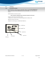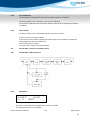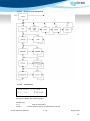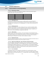
1
Zenyth 340 Microplate Reader User’s Manual Biochrom Ltd 22 Cambridge Science Park Cambridge UK CB4 0FJ Tel.: +44/1223 423723 E-Mail: [email protected] Zenyth 340 User’s Manual v. 1.0 August 2010 2 Table of Contents: Safety Information……………………..…………………………………….5 1 General Information ............................................................................................... 7 1.1 1.1.1 1.1.2 1.1.3 1.1.4 1.2 1.2.1 1.2.2 1.2.3 1.2.4 1.2.5 1.2.6 1.2.7 1.3 1.3.1 2 System Description .................................................................................................... 7 Model Versions...................................................................................................................... 7 Options ................................................................................................................................. 7 Intended use ......................................................................................................................... 7 Scope of Supply ..................................................................................................................... 7 Technical Data .......................................................................................................... 7 Table of Specifications ............................................................................................................ 8 Measurements and Weight .................................................................................................... 8 Power Supply ........................................................................................................................ 8 Sound Pressure Level ............................................................................................................. 8 Environmental Conditions ...................................................................................................... 9 Defects and Abnormal Stresses ............................................................................................... 9 Liability ................................................................................................................................. 9 Interfacing .............................................................................................................. 10 Zenyth 340r and 340rt .......................................................................................................... 10 Start-up and System Setup .................................................................................... 11 2.1 2.2 2.2.1 2.2.2 2.2.3 2.3 Unpacking and Installation ....................................................................................... 11 Calibration and Status-Check .................................................................................... 11 Lamp Adjustment: ............................................................................................................... 11 Auto-Calibration: ................................................................................................................. 12 Status Check: ....................................................................................................................... 12 Zenyth 340r/rt (remote controlled version) ................................................................ 12 2.3.1 Zenyth 340r/rt Menu Structure ............................................................................................. 12 2.3.2 Main Menu ......................................................................................................................... 12 2.3.3 Setup Menu......................................................................................................................... 13 2.3.3.1 Structure of the setup menu ......................................................................................... 14 2.3.3.2 Install Filters ................................................................................................................ 14 2.3.3.3 Set plate...................................................................................................................... 16 2.3.3.4 Language..................................................................................................................... 16 2.3.3.5 Serial communication ................................................................................................... 16 2.3.3.6 Check plate ................................................................................................................. 17 2.3.3.7 Temperature Control ................................................................................................... 17 2.3.3.8 New Temperature ........................................................................................................ 17 2.3.4 Define plate menu ............................................................................................................... 19 2.3.4.1 Define plate – menu structure ...................................................................................... 19 2.3.4.2 Define plate................................................................................................................. 19 2.3.5 Service Menu ...................................................................................................................... 22 2.3.5.1 Adjust Lamp ................................................................................................................ 22 2.3.5.2 Reset count ................................................................................................................. 23 2.3.5.3 Key click ...................................................................................................................... 23 2.3.5.4 Auto-calibration ........................................................................................................... 24 2.3.5.5 Change Air filter ........................................................................................................... 24 2.3.5.6 Service password ......................................................................................................... 24 3 4 Quick Start Guide ................................................................................................. 25 Maintenance........................................................................................................ 28 3.1 3.2 3.2.1 Electrical Safety Consideration .................................................................................. 28 Cleaning and Disinfection ......................................................................................... 28 Cleaning .............................................................................................................................. 29 Zenyth 340 User’s Manual v. 1.0 August 2010 2 3.2.2 3.3 3.4 3.5 Disinfection ......................................................................................................................... 29 Exchanging the fuse ................................................................................................. 30 Exchanging the air filter ........................................................................................... 30 Lamp and Interference Filter Exchange ...................................................................... 30 3.5.1 Required tools: .................................................................................................................... 30 3.5.2 Open the upper housing ....................................................................................................... 31 3.5.3 Lamp exchange .................................................................................................................... 31 3.5.4 Filter Installation .................................................................................................................. 32 3.5.4.1 Zenyth 340r/rt ............................................................................................................. 32 3.5.4.2 Using ADAP: ................................................................................................................ 32 4 Appendix: ............................................................................................................ 33 4.1 4.1.1 4.1.2 4.2 Principles of Photometry Measurement ..................................................................... 33 Absorbance Measurements .................................................................................................. 33 Measurement at Specific Wavelengths .................................................................................. 34 Evaluation applications: ........................................................................................... 35 4.2.1 Quick reference for test programming: .................................................................................. 35 4.2.1.1 Bichromatic reading: .................................................................................................... 35 4.2.1.2 Blank against Air: ......................................................................................................... 35 4.2.1.3 Shaking Function: ........................................................................................................ 35 4.2.1.4 Plate Layout: ............................................................................................................... 35 4.2.1.5 Blank Subtraction:........................................................................................................ 35 4.2.1.6 Single Point Calibration, Index Calculation, B/B0 Calculation: ........................................... 35 4.2.1.7 Use of Variables: .......................................................................................................... 35 4.2.1.8 Quantitative Evaluation: ............................................................................................... 36 4.2.1.9 Set-up of Standards and Axis Division: ........................................................................... 36 4.2.1.10 Use of Interpretation: .................................................................................................. 36 4.2.1.11 Validation:................................................................................................................... 36 4.2.2 Storing a Standard Curve ...................................................................................................... 37 4.2.3 Kinetic reading for extended range ELISA’s: ........................................................................... 38 Zenyth 340 User’s Manual v. 1.0 August 2010 3 Safety Information All Warnings and Cautions in this document include an exclamation point, a lightning bolt, or a light burst symbol framed within a triangle. Please pay special attention to the specific safety information associated with these symbols. Warning and Caution Definitions The exclamation point symbol is an international symbol which serves as a reminder that all safety instructions should be read and understood before installation, use, maintenance, and servicing is attempted. When this symbol is displayed in this manual, pay special attention to the specific safety information associated with the symbol. WARNING A WARNING calls attention to a condition or possible situation that could cause injury to the operator. CAUTION A CAUTION calls attention to a condition or possible situation that could damage or destroy the product or the operator’s work. Electrical Safety To prevent electrically related injuries and property damage, properly inspect all electrical equipment prior to use and immediately report any electrical deficiencies. Contact an Anthos service representative for any servicing of equipment requiring the removal of covers or panels. High Voltage: This symbol indicates the potential of an electrical shock hazard existing from a high voltage source and that all safety instructions should be read and understood before proceeding with the installation, maintenance, and servicing of all modules. 1. Voltages dangerous to human life are present in this device. Before removing any covers disconnect the device from the power source. 2. Ensure that the power cord supplied with the unit is used. 3. The power cord may only be inserted in a socket outlet provided with a protective ground (earth) contact. The protective action must not be negated by use of an extension cord without a protective grounding contact. 4. Do not replace fuses without first removing the main power cord. Ensure that only fuses with the required rated current and of the specified type are used for replacement. The use of makeshift fuses and the short-circuiting of fuse-holders is prohibited. 5. When the apparatus is connected to the main power source, the opening of the covers or removal of components is likely to expose life parts. The device shall be disconnected from all voltage sources before it is opened for adjustment or repair. Zenyth 340 User’s Manual v. 1.0 August 2010 4 6. Any adjustment or repair of the opened apparatus under voltage should be avoided, but, if necessary, it must be carried out by qualified service personnel who are aware of the hazards involved. 7. Use the equipment only in the intended manner and as specified by the manufacturer, otherwise the protection provided by the equipment may be impaired. 8. Only the IBM mouse, model No.: 12J3618, is tested for EMC compliance and is recommended to be used with the instrument. High voltage peaks in the mains supply may disable the function of a computer mouse connected to the reader. Unplug and re-plug the mouse and eventually re-boot the instrument for resuming its function. Use a voltage-peak filter between power cord and mains socket, if repeated failures of the mouse indicate the occurrence of voltage peaks in the mains supply. Chemical and Biological Safety Normal operation of the Zenyth 340 Absorbance Detectors may involve the use of materials that are toxic, inflammable, infectious or otherwise biologically harmful. When using such materials, observe the following precautions: 1. Handle infectious samples according to good laboratory procedures and methods to prevent the spread of disease. Wear protective gloves. 2. Observe all cautionary information printed on the original solutions containers prior to their use. 3. Dispose of all waste solutions according to your facility’s waste disposal procedures. 4. Operate the Zenyth 340 Absorbance Detectors in accordance with the instructions outlined in this manual, and take all the necessary precautions when using pathological, toxic, or radioactive materials. 5. Splashing of liquids may occur; therefore, take appropriate safety precautions, such as using safety glasses and wearing protective clothing, when working with potentially hazardous liquids. 6. Use an appropriately contained environment when using hazardous materials. 7. Observe the appropriate cautionary procedures as defined by your safety officer when using flammable solvents in or near a powered-up instrument. 8. Observe the appropriate cautionary procedures as defined by your safety officer when using toxic, pathological, or radioactive materials. 9. Wash your hands thoroughly after handling test fluids. If equipment has been in contact with hazardous substances, it must be disinfected prior to shipment in accordance with the effective provisions. Moving Parts Do not touch the plate during movement of the plate transport (risk of injury). Make sure that the lid is always closed prior to a measurement. Zenyth 340 User’s Manual v. 1.0 August 2010 5 Keep the Zenyth 340 Absorbance Detectors work area clear to prevent obstruction of the movement. Zenyth 340 User’s Manual v. 1.0 August 2010 6 1 General Information 1.1 System Description Zenyth 340 is a visible and near UV range instrument that uses a tungsten filament halogen lamp and automated wavelength selection via a filter wheel. Its mechanical concept is based on: Front loading, one-directional plate transport Fast moving scanning optics This allows flexible adaptation to all plate formats from 6 to 384 wells. 1.1.1 1.1.2 Model Versions Zenyth 340r Remote Controlled Filter Photometer Zenyth 340rt Remote Controlled Filter Photometer with Temperature Control Options Temperature Control ADAP-Software (3 modules available: ADAP Basic, ADAP Plus and ADAP Expert) A wide range of Filters 1.1.3 Intended use Zenyth 340 is intended for general laboratory and research use only. 1.1.4 Scope of Supply Filters 340, 405, 450, 492, 620 Manual Power cable Serial cable to PC Dust cover ADAP BASIC Software Adapter for keyboard and mouse (only S model) Spare air filters for fan (2) Spare fuses (2) 1.2 Technical Data Zenyth 340 User’s Manual v. 1.0 August 2010 7 1.2.1 Table of Specifications Parameter Measurement Method Light Source Detector Wavelength Range Filter-wheel Positions Available Wavelength Specification Transmission Photometer Tungsten Halogen Lamp Silicon Photodiode 340-750nm 8 340, 405, 450, 492, 550, 595, 620, other wavelengths on request Resolution Measurement Range Indication Range Accuracy Linearity 0.001 OD (0.1m OD in 0 – 1 OD) 0 - 3.0 OD (specified) 0 – 4.0 OD <±1.5% at 1 OD <±0.5% and ±0.005 OD from 0.1 up to 1.5 OD <±0.75% from 1.5 to 3.0 OD (400-750nm) <±0.7% and ±0.005 OD from 0.1 up to 2.0 OD (340-399nm) <±0.3% and ±0.005 OD at 1.000 OD (400-750nm) <±0.5% and ±0.005 OD at 2.000 OD (400-750nm) <±0.5% and ±0.005 OD at 1.000 OD (340-399nm) single wavelength: 10 Seconds dual wavelength: 20 Seconds kinetic single Wavelength Interval: 10 Seconds kinetic dual Wavelength Interval: 20 Seconds Reproducibility Measurement Speed for 96-Well Plate Assumed Workload Temperature Control Measurement Modes Shaking 1.2.2 5000 Measurements / Year from 4° C above Ambient up to 45°C in 1° C Steps single wavelength dual wavelength multiple wavelength scan measurement kinetic measurement three speeds Measurements and Weight Weight: 14.4 kg Dimensions (width x height x length): 47.3 cm x 25.0 cm x 39.8 cm 1.2.3 Power Supply Operating voltage: 100-240 V, frequency range: 50-60 HFuses: 250VAC, 2 A -T, 5x20 mm, 1.2.4 Sound Pressure Level Maximum sound pressure 71dBA Maximum sound pressure at one meter 62dBA Zenyth 340 User’s Manual v. 1.0 August 2010 8 1.2.5 Environmental Conditions The working area has to be flat, dry, clean and vibration proof and leave additional room for cables, connections, computer, printer etc. The ambient air has to be clean and free of corrosive vapors, smoke and dust. The instrument is rated to Pollution Degree II and Installation Category II. The ambient temperature has to range between 15°C and 40°C for operation and between -25°C and +50°C for storage. Indoor use only. Humidity has to range between 15% and 75%. Height over sea level during operation up to 2000 m 1.2.6 Defects and Abnormal Stresses Whenever it seems likely that safe operating conditions are impaired, the instrument shall be made inoperative , for example, remove the Power Cord, etc., and shall be secured against any unintended operation. Mark the device as unsafe for use. This is the case if the device for example: 1.2.7 shows signs of visible damage. fails to perform its intended functions. has been subjected to prolonged storage under unfavorable conditions. has been subjected to severe transport stress. Liability In original condition the instrument meets all safety regulations for a risk-free operation. Biochrom Ltd cannot warrant damages or any resulting costs caused by alterations, repairs or modifications of the equipment. Zenyth 340 User’s Manual v. 1.0 August 2010 9 1.3 Interfacing 1.3.1 Zenyth 340r and 340rt Serial Interface for remote control via ADAP Basic. Refer to chapter Error! Reference source not found., Error! Reference source not found., and to the ADAP user manual. Parallel Interface to connect a printer Note: All printers which have PCL transmission protocol can be used. PS2 port to link mouse or keyboard or both 2 USB ports for connection to an external floppy drive or memory stick VGA port to link to a PC screen LAN port for connecting to a network (See chapter 5). 2 USB Ports Parallel Port Serial Port VGA port LAN Port PS2 Port Zenyth 340 User’s Manual v. 1.0 August 2010 10 2 Start-up and System Setup 2.1 Unpacking and Installation The original Zenyth 340 packing has been especially designed to protect this equipment during transportation. It is therefore recommended to keep the original carton with its foam parts and the accessories box for re-use in case of future shipments. Warranty claims are void if transport damages are caused by improper packing. Unpacking of Instrument Check the box for any visible damage during transportation. In case of damage inform your supplier immediately and keep the damaged packing Place the device on a suitable working surface Connect the power cable Connect the serial cable to the PC used for Switch on main switch (rear left side). The Anthos Zenyth 340 performs the complete initialization and shows the main menu after approx. 30 seconds. 2.2 Calibration and Status-Check Before the first use of the instrument after shipment a few automated re-adjustments and a status check shall be performed in the following sequence: 2.2.1 Lamp Adjustment: The brightness of the halogen bulb is adjusted for each filter installed. For Zenyth 340r/rt refer to chapter: 2.3.5.1, Adjust Lamp Activate Adj. Lamp and wait until the automatic procedure is finished. Zenyth 340 User’s Manual v. 1.0 August 2010 11 2.2.2 Auto-Calibration: The movement of the plate transport and the optics transport is adjusted For Zenyth 340r/rt refer to chapter: 2.3.5.4, Auto-calibration Scroll to Auto-calibration and activate the function. Wait until the automatic procedure is finished. 2.2.3 Status Check: For Zenyth 340r/rt refer to the ADAP software instruction manual: Press function key F1 <Quick Check>: A self-test of the instrument is performed, which reports the parameters stored after Lamp Adjustment and Auto-Calibration. Press function key F2 <Save>: The report file is stored in the selected path. 2.3 Zenyth 340r/rt (remote controlled version) 2.3.1 Zenyth 340r/rt Menu Structure 2.3.2 Main Menu Cur:XX.X° Set:XX << >> EJECT This menu is standard menu if temperature control is installed. If temperature control is not installed: Zenyth 340 User’s Manual v. 1.0 August 2010 12 ANTHOS << >> ZENYTH EJECT Note: Only at this menu point, the Zenyth 340r/rt reader can establish a communication with an external PC via serial interface (RS232). Useable keys: <<, >> Scroll through the menus +/Eject the plate, if plate is not inserted: Load plate. <enter> Eject plate, if plate is not inserted: Load plate. 2.3.3 Setup Menu In the setup menu, the following features of the Zenyth 340r/rt reader can be performed: Filter installation Set Plate Language settings Communication protocol (ASTM or HT-protocol) Plate check Zenyth 340 User’s Manual v. 1.0 August 2010 13 2.3.3.1 Structure of the setup menu 2.3.3.2 Install Filters Install Filter << >> Filter This menu is shown when selecting filters. Useable keys: <<, >> <enter> back to setup menu confirm selection and go to submenu filter install Zenyth 340 User’s Manual v. 1.0 August 2010 14 Filter1 Esc 1 ___ nm Useable keys: << select filter esc go back to install filter menu +, select wavelength, 340-800 nm <enter> confirm selection If wavelength is changed, filter installation is done immediately. If wavelength isunchanged the following screen will appear. Adjust Lamp? Esc No This menu is used whether lamp adjust to specified filter should be done or not. Useable keys: esc go back to previous filter menu +,select yes or no <enter> confirm selection and adjust lamp for filter V:___ G:_ Filter1: ___ nm This menu appears when select 'yes' above. V: value of Digipoti G: value of pre amplifier esc go back to previous filter menu (V and G are increased until ADC values reach required value. ) This process can't be interrupted by user. Lamp adjust can take up to 30 seconds per filter. After the lamp is adjusted the filter adjust procedure for the next filter is started. The user has to follow the whole submenu until he has reached filter number 8. After the user pressed enter the data is updated and written to EEPROM. Lamp Adjust Adjust: Zenyth 340 User’s Manual OK v. 1.0 August 2010 15 After lamp is adjusted, result of adjustment is displayed. If lamp energy is too low so that the energy needed for measurement can't be reached, NOK is displayed. Check lamp afterwards or optic system. Useable keys: all keys are used to confirm 2.3.3.3 Set plate SetPlate Esc TEST This screen is used to select standard plate for measurements. If HT protocol only 96 well plates are displayed. This feature is implemented especially for HT-protocol users. Useable keys: Esc +,<enter> 2.3.3.4 go back to setup menu select plate confirm selection Language Language Esc English Language Esc English This screen is used to change language for Zenyth 340r/rt. Useable keys: esc go back to setup menu +,select language <enter> confirm selection 2.3.3.5 Serial communication Setup << >> RS 232 This screen is used to select the serial communication protocol. The user can select either HT type communication or ADI type communication. If submenu protocol is selected: RS 232 Zenyth 340Esc User’s Manual ADI Typev. 1.0 August 2010 16 Useable keys: Esc +,<enter> 2.3.3.6 go back to setup menu select communication type confirm selection Check plate Plate check Esc On This screen is used to activate or deactivate plate check. If plate check is activated measurement procedures are stopped if no plate is inserted in device. Useable keys: Esc go back to setup menu +,select On/Off <enter> confirm selection 2.3.3.7 Temperature Control Temperature << >> TempCtl This screen is used to set temperature on Useable keys: <<, >> scroll through main menus +,not used <enter> confirm selection 2.3.3.8 Zenyth 340rt. New Temperature New Temperature Esc Off 30° This screen is used to turn temperature control On or Off and to set temperature. The temperature has to be set 4° higher than room temperature. If temperature is too low a warning is displayed: 'temperature too low'. Confirm warning and enter higher temperature. Useable keys: Esc go back to main menus >> change between On or Off Zenyth 340 User’s Manual v. 1.0 August 2010 17 +,<enter> change temperature confirm selection Zenyth 340 User’s Manual v. 1.0 August 2010 18 2.3.4 Define plate menu The Anthos Zenyth 340r/rt reader can measure the standard plate formats 6/12/24/48/96/384. Additionally the software can manage a tuning of the above mentioned well formats. 2.3.4.1 Define plate – menu structure 2.3.4.2 Define plate This menu is used for the definition of different plate types and parameters. A plate definition determines the center position of the wells for optimized adaptation of the measurement system to mechanical plate parameters. Plates must not have the same plate name. A maximum of 90 plates can be defined. Def Plate: << >> Useable keys: <<, >> Zenyth 340 User’s Manual <new> Scroll through the menus. v. 1.0 August 2010 19 +,<enter> Scroll through the Def Plate menu. Enter the selected Def Plate menu. Name: Esc Chg _____ This screen is used to edit new plate name. Useable keys: Esc Chg <enter> Name: leave the menu. changes the name of the plate. confirm name selection of new plate Esc Sel _A This screen is used to enter plate name of new plate. Useable keys: Esc leave the menu. Sel Selects the letter or number. +,scroll through alphabet and numbers <enter> confirm selection after whole name is edited PlateFormat << esc 96 This screen is used to select plate format (6, 12 , 24 , 48, 96, 384 well plate) Useable keys: Esc leave the menu. +, toggle between the different plate formats (6 well, 12, 24 , 48, 96, 384). << back to previous menu item <enter> Confirm selection. Zenyth 340 User’s Manual v. 1.0 August 2010 20 In the diagram all parameters for a new plate-definition are displayed. In the following section documentation is shown how to define a new plate. 1 A0 Y 2 3 Delta Y A0 X A Well diameter Delta X B A1 Pos X: << Esc 0.01mm This screen is used to Define X position of A1 well on plate in mm. Useable keys: Esc leave the menu. +, Decrements/Increments the position. << back to previous menu item <enter> Confirm selection. A1 Pos Y: << Esc 0.01mm This screen is used to Define Y position of A1 well on plate in mm. Useable keys: Esc leave the menu. +, Decrements/Increments the position << back to previous menu item <enter> Confirm selection. Delta X: Zenyth 340<< User’sEsc Manual 0.1mmv. 1.0 August 2010 21 This screen is used to define the difference between the center of wells A1 to B1 in mm. Useable keys: Esc Leaves the menu. +, Decrements/Increments the position. << back to previous menu item <enter> Confirm selection. Delta Y: << Esc 0.1mm This screen is used to define the difference between the center of wells A1 to A2 in mm. . Useable keys: Esc Leaves the menu. +, Decrements/Increments the position. << back to previous menu item <enter> Confirm selection. Well Diameter: << Esc 0.1mm This screen is used to Define diameter of well. Useable keys: Esc Leaves the menu. +, Decrements/Increments the position. << back to previous menu item <enter> Confirm selection and store values in flash 2.3.5 Service Menu 2.3.5.1 Adjust Lamp Service << >> Zenyth 340 User’s Manual Adj Lamp v. 1.0 August 2010 22 This screen is the main screen of service. Useable keys: <<,>> Select "<<" or ">>" to change to main screen <+>,<-> Use these keys to choose service items. <enter> Use this key to select service items. Adjust Lamp No YES This screen is used to adjust all installed filters automatically. If this menu is chosen the filter adjust procedure starts and all filters will be adjusted. On display the current filter being adjusted is shown. Useable keys: <F1>,<F2> <+>,<-> <enter> 2.3.5.2 select adjust lamp (YES) or not (NO) not used not used Reset count Reset Count No YES This screen is used to reset cycle count. After 10000 measurements the user is told to-“Do Service”. After the user confirmed the warning, the warning will be repeated every 100 cycles until the user or service resets count. Useable keys: <F1>,<F2> <+>,<-> <enter> 2.3.5.3 reset (YES), do not reset (No) not used not used Key click Keyclick << ESC On Zenyth 340 User’s Manual v. 1.0 August 2010 23 This screen is used to turn key click on or off. Useable keys: <F1>,<F2> <+>,<-> <enter> 2.3.5.4 used to go back to service main menu used to change between on or off confirm selection Auto-calibration Autocalibration No YES This screen is used to confirm auto calibration. In this procedure zero position for plate and fork transport are calculated and measured. Afterwards the new parameters are written to eeprom Useable keys: <F1>,<F2> Yes , No <+>,<-> not used <enter> Use this key to change to main menu. If calibration was ok, it is displayed on screen. Press any key to continue afterwards. 2.3.5.5 Change Air filter AirFilt changed? No YES This screen is used to reset air cycle count. After 500 hours the user is told to change air filter. After the user confirmed the warning, the warning will be repeated every 10 hours until the user or service resets count. The default interval is adjustable in eeprom. Useable keys: <F1>,<F2> reset (YES), do not reset (No) 2.3.5.6 Service password This area is restricted to service technician and is therefore protected with password. Service << >> Serv.Pwd Zenyth 340 User’s Manual v. 1.0 August 2010 24 3 Quick Start Guide 1. To turn on the instrument: Connect instrument to a power source using the appropriate power cord. Check user’s manual for important safety information. 2. To connect the instrument to a PC: Connect to a PC via serial port to serial port or a serial to USB port adaptor. Determine the communication port (com) used by the instrument. In the Start menu of the PC, go to Control Panel\System\Hardware\Device Manager\Ports. 3. To connect instrument to ADAP software: Insert CD supplied with the instrument into PC, install ADAP. Open ADAP. ADAP will prompt for a user ID and password. Use the pre-set ID and passwords are sadmin\sadmin. Once logged as sadmin, set specific user IDs, passwords and administrative rights. Select Setup>Instrument in the menu bar. A dialogue box will open: Under the Instrument tab: In Baudrate: select Auto Sense In COM Port: select port or Auto Sense In Instrument Type: select Zenyth in the drop-down menus. 3. To measure a plate: Go to Reading>Quick or the R button in the task bar. To confirm that the instrument is connected with the computer, select the Read Configuration button. The serial number of the instrument should now appear in the Setup>Instrument dialogue box along with compatible plate types. In the Quick-Read dialogue box: Confirm that the correct format and plate type are selected. Select All in Measurement Position to read the entire plate. Select Endpoint Photometric for basic readings using a measurement and reference filter from the drop-down menu. Zenyth 340 User’s Manual v. 1.0 August 2010 25 Note: It is important to use a reference filter to account for optical inference from the plate. Place plate with A1 in the upper left corner of the plate transport. Select Start. Absorbance measurements will appear in the open matrix in ADAP. Data can be exported to data analysis software using the Copy icon. Data will paste as a matrix with filter wavelength, time and date. Zenyth 340 User’s Manual v. 1.0 August 2010 26 Zenyth 340 User’s Manual v. 1.0 August 2010 27 4 Maintenance ATTENTION: Read these pages entirely and carefully! All maintenance work requiring opening of the instrument must be performed only with mains disconnected and must be performed by a technical qualified person! 3.1 Electrical Safety Consideration See also Safety Information at the beginning of this manual ATTENTION: Voltages dangerous to human life are present in this device. Read these pages entirely before opening any seal or unscrew the instrument When the instrument has to be opened for a lamp- or filter exchange the device must be disconnected from the power source. Ensure that only fuses with the required current rate and of the specified type (2 A T) are used for replacement. The use of makeshift fuses and the short-circuiting of fuse-holders are prohibited. When the instrument is connected to the main power source, the opening of covers or removal of components is likely to exposed live parts. The device must be disconnected from all voltage sources before it is opened for any exchange or cleaning. Any adjustment or repair of the opened instrument under voltage should be avoided, but, if necessary, it must be performed by qualified service personnel who are aware of the hazards involved. 3.2 Cleaning and Disinfection All parts of the reader that come into contact with potentially infectious material must be treated as potentially infectious areas. The cleaning and disinfection procedures should be performed by authorized trained personnel in a well-ventilated room while wearing disposable gloves, protective glasses and clothing. The following materials are recommended for cleaning and disinfection of the reader: lint-free tissues. Protein degrading mild detergent (e.g. Mucasol / Rogypon) or saline solution (0.9% NaCl). Ethanol (70%) or chlorine solution (1500 ppm). Never spray directly into the interior of the reader. Zenyth 340 User’s Manual v. 1.0 August 2010 28 3.2.1 Cleaning Clean the reader regularly and immediately after spillage. This has to be done with due care and attention. Always observe laboratory safety rules and regulations. Do not use force when cleaning the reader. Wipe off spills immediately with soft tissue. Avoid sedimentation of dust on the instrument and wipe off visible dust. Cover the instrument with the dust cover if not in use. The following cleaning procedure should be performed on demand: 1. Switch off the reader. 2. Carefully wipe off the entire reader with lint-free tissues that have been moistened in a mild protein degrading detergent or a saline solution. 3. Carefully wipe off the entire reader with lint-free tissues that have been moistened in ethanol or a chlorine solution. 4. Put lint-free tissues that have been moistened in ethanol or a chlorine solution onto the plate transport mechanism and let it soak for ± 30 minutes. 5. When a chlorine solution has been used, carefully wipe off the entire reader with lint-free tissues that have been moistened in water. 6. Dry the reader by wiping it off with lint-free tissues. 3.2.2 Disinfection Before the reader is returned to the distributor it must be disinfected and a disinfection certificate must be completed. The following procedure must be used for disinfecting the reader: 1. Switch off the reader and disconnect it from the mains power supply. 2. When used, disconnect the reader from any accessories (printer and PC). 3. Carefully wipe off the entire reader with lint-free tissues that have been moistened in a protein degrading mild detergent or a saline solution. 4. Carefully wipe off the entire reader with lint-free tissues that have been moistened in ethanol or a chlorine solution. 5. Put lint-free tissues that have been moistened in ethanol or a chlorine solution onto the plate transport mechanism and let it soak for ± 30 minutes. 6. When a chlorine solution has been used, carefully wipe off the entire reader with lint-free tissues that have been moistened in water. 7. Dry the reader by wiping it off with lint-free tissues. 8. Pack the reader in its original packaging. 9. Complete a disinfection certificate and make a copy of the certificate. Enclose the disinfection certificate in the reader package and attach the copy to the outside of the package so that it is clearly visible. Zenyth 340 User’s Manual v. 1.0 August 2010 29 3.3 Exchanging the fuse In case of malfunction the fuses may be blown. They are positioned in the mains plug on the backside of the instrument. Remove the fuse-holder with a little flat screw driver and exchange the fuses (2A T) Two spare fuses are in the accessories-box). Put the fuse holder back into the mains plug 3.4 Exchanging the air filter 1. Remove the cover of the fan on the backside of the instrument. 2. Exchange the fleece. 3. Put on the cover again. 3.5 Lamp and Interference Filter Exchange 3.5.1 Required tools: Screwdriver for recessed-head screws Screwdriver flat 2,5mm Cotton buds (for filter cleaning) Zenyth 340 User’s Manual v. 1.0 August 2010 30 3.5.2 Open the upper housing Disconnect the instrument from the power source Open the two screws (M3x10) that fix the upper and the lower housing and open the upper housing. now you have the lamp and filters directly in front of you 3.5.3 Lamp exchange To remove the lamp unscrew the two screws in the coupler terminal that fix the cables (labeled with 1) Remove the distance that fix the complete lamp block (labeled with2) Take out the old lamp block and insert the new one by following the steps from behind toward the front 1 2 rubber band for filter ATTENTION: Take care not to touch the bulb of the new lamp. The position of the filament is pre-adjusted and when the position changes not enough energy is present. Re-assemble the instrument and plug it to the mains After the new lamp is installed and the upper housing is fixed again, the lamp-energy for the filters has to be readjusted! See chapter 2.2.1, Lamp Adjustment:. Zenyth 340 User’s Manual v. 1.0 August 2010 31 3.5.4 Filter Installation Next to the filter motor you can see the filter wheel, which is surrounded by a rubber band. Choose the position where you want to change or add a new filter by turning the filter wheel (the numbers of the filter positions are indicated). Do not leave a filter position empty between installed filters. Pull the rubber band carefully and insert (exchange) a filter. Pay attention that the arrow on the filter frame shows to the right (direction of the light). The filter must be clean. Avoid dust or fingerprints. Re-assemble the instrument and plug it to the mains After the new filter is installed and the upper housing is fixed again, the filter wavelength has to be added to the list of installed filters and the lamp-energy for the filters needs to be readjusted in order to enable the new filter! 3.5.4.1 Zenyth 340r/rt See chapter 2.3.3.2, Install Filters for adding the new filter to the list. See chapter 2.3.5.1, Adjust Lamp for lamp adjustment. 3.5.4.2 Using ADAP: Refer also to the ADAP manual for further information Connect the reader with the PC (PC/PC-cable), turn the reader ON and start the software on the PC Enter the menu SETUP „READER and click the button READ CONFIGURATION Type in the new filter wavelength and click the button: SET FILTER Confirm the next message to adjust the lamp energy (of all installed filters) with YES. Zenyth 340 User’s Manual v. 1.0 August 2010 32 4 Appendix: 4.1 Principles of Photometry Measurement Light is electromagnetic wave radiation. Rays from 100nm to 400nm are defined as the ultraviolet spectrum of light. Only rays in the range from 400nm to 780nm are visible to the human's eye, rays with longer wavelengths are called infrared. Color impressions are caused by reflection of electromagnetic waves striking the surface of material substances. Substances absorb the complementary spectrum of their visual perceptible color. Hence green plants look green since they absorb red light (light of a wavelength perceived as red, e.g.: 750nm). A photometer is an optical electronic measuring device to determine the amount of light absorbed at a specific wavelength. 4.1.1 Absorbance Measurements Experimental measurements return the value of transmission (T): Transmission is defined as the percentage ratio between the total available light energy at the detector (measured through air) and the residual luminous energy after sample transmission at a specific wavelength. T = I/I0 (I.....Light intensity after passing through the sample I0....Initial light intensity) Transmission has no linear relation to concentration; therefore Absorbance (Optical Density) is calculated from Transmission by the formula: A = OD = -log T, or A = OD = log (1/T) Absorbance is related in a linear way to layer thickness and sample concentration according to the Beers law: The following graph illustrates the relation between absorbance (sample concentration) and the light transmitted and measured at the detector: Absorbance (A) =Molar Absorptivity(ε) * pathlength (b) * concentration (c) Zenyth 340 User’s Manual v. 1.0 August 2010 33 It is important to keep in mind that the best measurement range of absorbance is from 0.1 to 1 OD or 90% to 10% of transmission. Measurements above 2 OD deal with less than 1% of the original light and will therefore have lower resolution and accuracy. 4.1.2 Measurement at Specific Wavelengths A useful physical characteristic of molecules is specific transmission profile which is indicative of its concentration and composition. A measurement with white light renders different sample concentrations in a certain spectral range only to a small amount and accordingly inaccurate. A higher significance can be obtained by using only that part of the light spectrum, which is relevant to prove the respective wavelength of the substance. Due to this fact interference filters of a narrow banded wavelength spectrum are employed in this instrument. Each substance has a certain absorption spectrum. A measurement should be performed by selecting the correct filter for the maximum absorption of the sample, because in this way the best differentiability of various sample concentrations can be reached. We can also state that the differing absorption amplitude of two uniformly composed samples is a measure for the concentration. For this reason measurements in the flank area of the spectrum are not very accurate and therefore to be avoided. In this connection, it has to be taken into consideration that - when using interference filters – wavelength tolerances of +/- 2 nm from the nominal wavelength value may also result in inaccuracies. Each sample has an absorption minimum not specific to the measurement value, which can be deducted from the measurement value automatically by choosing a suitable reference wavelength. This kind of measurement is referred to as bichromatic. Zenyth 340 User’s Manual v. 1.0 August 2010 34 4.2 Evaluation applications: 4.2.1 Quick reference for test programming: 4.2.1.1 Bichromatic reading: It is highly recommended to use a reference reading for subtracting unspecific signals. Suited measurement and reference filters are: Substrate: PNPP TMB OPD ABTS Measurement Filter: 405 nm 450 nm 492 nm 405 (414) nm Reference Filter: 620 nm 620 nm 620 nm 492 nm 4.2.1.2 Blank against Air: An automatic self-calibration (determination of 100% and 0% transmission signals) is performed by the reader for each measurement channel and each particular filter previous to readings. This is equivalent to the "blanking against air", which is often mentioned in kit instructions. 4.2.1.3 Shaking Function: It is highly recommended to use a short shaking cycle (e.g. 5 seconds) at medium speed previous to measurements. This will homogenize the color solution (color develops at the edges of the well) and will produce an equal and stable liquid meniscus in all wells. As a result accuracy and reproducibility are significantly improved. 4.2.1.4 Plate Layout: Singles or replicates of blanks, standards, controls and samples may be distributed freely across the plate. There are no fixed positions used for calculations. The software will find the right wells according to the set names in the plate layout. The mean value is calculated automatically for all replicates of a blank, control, standard or sample. 4.2.1.5 Blank Subtraction: The mean of positions marked as B (blank) is subtracted automatically from all other wells. If a blank should not be subtracted, it has to be named as a control. 4.2.1.6 Single Point Calibration, Index Calculation, B/B0 Calculation: The Transformation Formula allows calculating a ratio to a particular control for all other controls, standards and samples. A common application is the calculation of the percentage of binding with competitive assays (e.g. X‘ = X/C1*100, where C1 is the maximum binding control). With the use of additional concentration factors and correction factors, this formula provides also single point calibration and cut-off ratios. On the printout the result of this formula is reported with its given name. 4.2.1.7 Use of Variables: Lot dependent values, such as calibrator concentrations or correction factors, may be programmed as variables. Enter default values for the number of variables required. During programming you can use the names V1, V2, …etc which refer to the list of defined variables. Zenyth 340 User’s Manual v. 1.0 August 2010 35 At the beginning of each measurement the variables are displayed for review. At this time permanent changes can be made, so that the values are kept according to current kit lots. 4.2.1.8 Quantitative Evaluation: Concentrations are calculated by means of the calibration curve. Linear regression is specifically applicable, if the calibration curve is really expected to be straight on a linear or logarithmic concentration axis. Point to Point and Cubic Spline curve fits are generally suited for non-linear curves. However, the Cubic Spline will not tolerate big jumps and turning points and will show a tendency to swing out at such occasions. Point to Point may not be that accurate, but is completely save and robust under all conditions. For both the concentration axis has to be selected linear or logarithmic, according to the sequence of standard points: The 4-parameter Fit is a non-linear regression, especially suited for competitive assay formats. Its theory assumes a point of inflection and two asymptotes at the extreme ends. The axis division is fixed to lin/log. Zero concentration standards must not be included in the curve, but in case of competitive assays they should be named as negative controls (e.g. NC1) and may serve for the calculation of B/B0 by means of the relational formula (X/NC1*100). The 4-parameter fit is also generally suited for non-linear curves with sandwich assays. If a turning point is not present, it will adapt to the lower or upper branch of a sigmoid curve. It is more stable than the Cubic Spline and will never overshoot, but may need slightly longer calculation times. Extrapolation, set in %, allows calculating sample concentration also in a small area below and above the extreme standards. Extrapolated results are marked on the printout with an "X". Results out of range are shown with the prefix > or < to the highest or lowest valid concentration (border of extrapolated area). A few percent extrapolations are recommended, in order to get both replicates of extreme standards into the valid area for results (otherwise the mean of replicates is the borderline). 4.2.1.9 Set-up of Standards and Axis Division: Standards have to be entered in increasing order of concentrations always (lowest concentration S1). In case of competitive assays, this will produce a falling curve. If the standard series is produced by a more or less constant adding. (e.g. 10; 20; 30;... or even 10; 20; 40; 70; ...), the axis division is linear. If there is a multiplication (dilution) factor (e.g. 2; 4; 8; 16; .., or 10; 33; 100; 330; ...), the axis division is logarithmic. Zero concentration standards must not be used on a logarithmic scale for mathematical reasons. If such a standard sequence is suggested in the kit instructions, do not use the zero standard for the curve (recommended) or set it to a small positive value, two logs below the second standard (e.g. 0.02; 2; 4; 8; ...) The identifiers for standards on the plate (S1 – SXL) may be replaced by fixed OD-values or formulas. This allows to use stored standard curves with correction factors (refer to 4.2.2, Storing a Standard Curve). 4.2.1.10 Use of Interpretation: The "Interpretation" section provides not only cut-off calculation based on optical density. If the calculation base is set to the result name of the Transformation or to Concentrations, also these results may be grouped by means of the cut-off formulas. Free names can be given to the groups (up to five). 4.2.1.11 Validation: The validation formulas describe true conditions on basis of optical density values. Zenyth 340 User’s Manual v. 1.0 August 2010 36 A bold warning will be stated on the printout, if one of the validation criteria’s is not fulfilled. 4.2.2 Storing a Standard Curve Note: The use of stored standard curves is not generally recommended or applicable for the quantitative evaluation of ELISAs. It is explicitly the responsibility of the user to take advantage of the described software possibilities in the appropriate way! Once a standard curve has been measured and OD results have been obtained (by programming for standard S1 the response value as S1, for the standard S2 as S2, etc.), the curve can be copied to another test procedure the in the following way: Make a printout of the measured plate with standards, containing both concentration values and OD values. Copy the original test procedure to a new file by changing the name and editing the test (a copy will be stored under the new name). Put in the OD-values of the measured standards S1 – Sx as default values for Variables V1 – Vx The layout does not need to contain a real standard anymore. Fill the plate just with samples As response values enter the variables V1 – Vx instead of the standards S1- Sx When starting a reading with the new test, the variables are displayed and may be updated to the last reading of a standard series. In order to correct plate to plate variations of the assay, it is highly recommended to have at least one real standard on the plate by which a correction factor is calculated. The correction factor is the actual measurement value divided by the initial measurement value of the repeated standard. Example: A plate with 5 standards is programmed: Standard Points Concentration Values Response Formulas S1 0.1 S1 S2 1 S2 S3 10 S3 S4 100 S4 S5 1000 S5 A new test is programmed: The measured OD’s of the standards are entered to the variables: Standard Points Response Values [OD] Put to Variables S1 0.3 V1 S2 0.6 V2 S3 0.8 V3 S4 0.9 V4 S5 1.0 V5 Only standard S3 is used on the plate-layout of the new test. It is named C1 (control) and its measured value is used to calculate the correction factor for all other standards: Standard Points S1 Concentration Values 0.1 Response Formulas V1*(C1/V3) S2 1 V2*(C1/V3) S3 10 V3*(C1/V3) S4 100 V4*(C1/V3) S5 1000 V5*(C1/V3) If the actual measurement value of the standard 3 (C1) deviates from the original measurement value (V3), all standards are re-adjusted by the correction factor C1/V3 corrected: Zenyth 340 User’s Manual v. 1.0 August 2010 37 Fig. 5: Standard Curve Graph 4.2.3 Kinetic reading for extended range ELISA’s: With photometry endpoint readings, the logarithmic scale of optical density may be a limiting factor for some ELISA applications. Quantification of TSH, for instance, would benefit from a broader dynamic range than normally available. If the substrate is TMB then the measurement range of the assay can be extended by kinetic reading. The result of the kinetic data reduction (e.g. mOD/min) may be used as the basis for any further quantitative and/or qualitative evaluation. The maximum slope (maximum reaction speed) of the color development at 620 nm corresponds to the amount of bound enzyme. (In fact, stopping of the color reaction means setting of an artificial endpoint and uses also the different reaction speed of different enzyme concentrations). Example of Test Parameters : Measurement filter: Interval time: Number of readings: Interval shaking: Data reduction: 620 nm 20 seconds 30 up to 40 3 - 5 seconds, medium speed Maximum slope Most probably, the total kinetic measurement time can be set shorter than the normal substrate incubation time. TMB measured in the blue phase at 620nm has about one third of the optical density than the same concentration measured after stopping in the yellow phase. Samples and standards, which would reach "overflow" in an endpoint reading, will remain within the good measurement range during kinetic readings. Therefore the dynamic range and accuracy of ELISA‘s may be significantly improved with kinetic readings. A main advantage of kinetic readings is the elimination of the critical timing between adding of substrate and stopping solution for all wells. Zenyth 340 User’s Manual v. 1.0 August 2010 38