Transcript
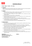
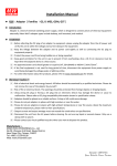
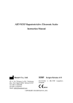
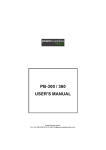
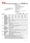
2.This charger is equipped with output voltage and current adjusting features, that is, the output voltage and output current parameters can be adjusted by the user via internal potentiometers. I o ADJ. is used to adjust the current while Vo ADJ. can be used to adjust the output voltage (VFLT). The adjustable range is as follows: Tcase 126.6mm Io Vo ADJ. ADJ. 47mm I/P 1 2 3 1 2 3 4 O/P 5 6 7 Model Voltage Adj. Range Current Adj. Range HEP-600C-24 23 ~ 30.2V 10.5 ~ 21A HEP-600C-48 46.1 ~ 60.5V 5.2 ~ 10.5A Caution: Vo ADJ. should be adjusted while the charger is not connected to a battery. The adjustment will also affect the Vboost voltage. For example if the original VFLT was 13.6V, Vboost 14.4V, adjusting VFLT during no load to 13.2V will also adjust Vboost to 14V. Before adjusting the voltage, users should inquire battery manufacturer what voltage is suitable for charging to prevent over or under charging the battery. LED ※ Tcase: Point of highest case temperature HEP-600C-12 11.5 ~ 15.1V 17.5 ~ 35A Charging current and operating ambient temperature curve is shown in the figure below: 100 80 Pin No. 1 2 3 HEP-600C DC Output Terminal Pin No. Assignment Assignment FG AC/L AC/N Pin No. 1 2 3 Assignment RC+ RC- & GND +5V SB Pin No. 4,5 6,7 Assignment -V +V 60 Load (%) AC Input Terminal Pin No. Assignment 40 20 Safety Guidelines: 1.Keep the HEP-600C away from spark or flame to avoid danger of explosion. -40 -25 2.While charging batteries in series, do not mix old and new batteries in the same series. USER'S MANUAL 3.Before charging, please verify that the charging voltage and current of the HEP-600C are suitable for the prospective battery. 4.Please do not stack any objects on the case of the HEP-600C. Please make sure case temperature is under 75°C to maintain proper heat dissipation in order not to affect -10 0 15 30 50 55 60 Output wire gauge selection: Select appropriate wire gauge according to charging current. The minimum requirements are in the table below. Warning: Small or inappropriate wiring will cause the wire to product lifetime. 5.Do not try to use the HEP-600C to charge non-rechargeable batteries or frozen batteries. overheat and cause possible fire hazard 6.This charger may possess high temperature during operation. Please do not touch the case. 7.If the FG connection on the AC input terminal cannot be connected to PE (protective earth), then the chassis will need to be grounded or the leakage current may harm the users who touch the case. 8.When connecting or disconnecting wires, please ensure the charger is OFF. AWG 2 CROSS SECTION(mm ) 12 14 16 18 3.309 2.081 1.309 0.823 MODEL OUTPUT INPUT HEP-600C-12 HEP-600C-24 HEP-600C-48 BOOST CHARGE VOLTAGE 14.4V 28.8V 57.6V FLOAT CHARGE VOLTAGE 13.6V 27.2V 54.4V VOLTAGE ADJ. RANGE 11.5 ~ 15.1V 23 ~ 30.2V 46.1 ~ 60.5V CURRENT ADJ. RANGE 17.5 ~ 35A 10.5 ~ 21A 5.2 ~ 10.5A 70 ~ 210AH 35 ~ 105AH 21A 10.5A RECOMMENDED BATTERY 135 ~ 400AH CAPACITY(AMP HOURS)(Note 2) BATTERY TYPE Open & Sealed Lead Acid OUTPUT CURRENT 35A VOLTAGE RANGE 90 ~ 264VAC FREQUENCY RANGE 47 ~ 63Hz POWER FACTOR (Typ.) PF>0.98/115VAC, PF>0.95/230VAC, PF>0.93/277VAC at full load EFFICIENCY (Typ.) 93.5% 7A / 115VAC INRUSH CURRENT (Typ.) COLD START 70A(twidth=1010μs measured at 50% Ipeak) at 230VAC LEAKAGE CURRENT <0.75mA / 240VAC OVER VOLTAGE Warning: Before connecting a battery, please make sure the polarities are correct to avoid damaging the charger Assembly Procedure: 1.Please make sure the charger is OFF before connecting the battery to the output terminal. Choose a cable with suitable wire gauge according to the charging current to connect 95.5% 2.9A / 277VAC Terminal(+) to Battery(+); Terminal(-) to Battery(-), and take notice that the positive and negative polarities are not shorted. 2.After applying AC to the charger, check the color of the LED indicator. If it is red, then the battery is being charged ; If the LED is green, then the battery is already fully charged. 16.5 ~ 20.5V 32.5 ~ 36.5V 68 ~ 73V OVER TEMPERATURE Shut down o/p voltage, re-power on to recover At the beginning stage of operation, the charger provides the largest current with 14.4Vdc REMOTE ON/OFF CONTROL Power on : "Hi" >2 ~ 5V or Open circuit 5V STANDBY 5VSB : [email protected] ; tolerance ±5%, ripple : 100mVp-p(max.) of output voltage(for 12V batteries) to charge batteries, the LED indicator will lighten in WORKING TEMP. -40 ~ +70℃ (Refer to "Derating Curve") red. After a period of time (probably a couple of hours, based on the capacity of the batteries), 20 ~ 95% RH non-condensing the charging current will decrease gradually. When the charging current is below 50% -40 ~ +85℃, 10 ~ 95% RH of the largest current, the LED indicator will turn yellow . After reducing to 10% of its maximum Power off : "Low" <0 ~ 0.5V or Short circuit TEMP. COEFFICIENT ±0.05%/℃ (0 ~ 60℃) VIBRATION 10 ~ 500Hz, 5G 10min./1cycle, 72min. each along X, Y, Z axes value, the charger will go into “float charge” stage. Output voltage will drop to 13.6V and SAFETY STANDARDS UL60950-1, TUV EN60950-1 approved the LED indicator will turn to green. The relationship between charging current and I/P-O/P:3KVAC charging voltage for each operation stage is shown in the curves below: I/P-FG:2KVAC O/P-FG:1.5KVAC I/P-O/P, I/P-FG, O/P-FG:100M Ohms / 500VDC / 25℃/ 70% RH Compliance to EN55022 (CISPR22), radiation class A, conduction class B, EN61000-3-2,-3 Start V boost Compliance to EN61000-4-2,3,4,5,6,8,11, EN55024, light industry level, criteria A EMC IMMUNITY MTBF 73.1K hrs min. DIMENSION 280*144*48.5mm (L*W*H) PACKING 3.9Kg; 4pcs/16.6Kg/0.9CUFT V FLT MIL-HDBK-217F (25℃) ℃ Charge Voltage 100% Model Recommended Capacity of Battery HEP-600C-12 HEP-600C-24 HEP-600C-48 135-400Ah 70-210Ah 35-105Ah Note:1.W hen the capacity of battery is larger than the recommended value, charging time will become longer but no harm will come to the battery. 2.If there are doubts on the allowable charging current for the battery, please refer to the technical data provided by the battery manufacturer or inquire the battery manufacturer. Troubleshooting: or shock hazard. If you are not able to clear the failure condition according to the following instructions, please contact us or your nearest distributor for repair service. Failure State Possible Reasons Recommended Solutions Output is reverse connected Return charger for repair No output voltage Over Temperature Protection Make sure the ventilation is not blocked and the ambient temperature is not too high. Has been charging for an extended amount of time but cannot reach float stage (green LED) Output wire is too small Choose an appropriate wire Battery is old or damaged Change to a new battery 50% Charge Current LED Color Model V boost V FLT Constant Current Constant Voltage stage 1 stage 2 stage 3 Yellow Green Red HEP-600C-12 14.4V 13.6V HEP-600C-24 28.8V 27.2V 10% HEP-600C-48 57.6V 54.4V Note:When charging a fully charged battery, it is normal if the LED indicator is either constant green or flashing as (1)RED YELLOW LED OFF GREEN 1 Applicable Battery Type: Lead Acid Any inappropriate use or unauthorized modification to the product may cause damage : Status under general operation SAFETY & WITHSTAND VOLTAGE EMC ISOLATION RESISTANCE (Note.3) EMC EMISSION NOTE 94.5% 3.3A / 230VAC Recommended capacity of battery: is available at a cost. Protection type : Shut down o/p voltage, re-power on to recover WORKING HUMIDITY ENVIRONMENT STORAGE TEMP., HUMIDITY OTHERS 9.Under normal operating conditions, the HEP-600C has a 5 year warranty including free repairing services. If failure is caused by man or natural disaster then this service between the charger and the battery. Battery polarity must be connected correctly: AC CURRENT (Typ.) PROTECTION FUNCTION 127 ~ 373VDC Max.Current(A) UL1015(600V 105℃) 22 12 8 6 4 2 SPECIFICATION 70 (Horizontal) Ambient Temperature(℃) 3 MEAN WELL ENTERPRISES CO., LTD. No.28, Wuquan 3rd Rd., Wugu Dist., New Taipei City 248, Taiwan (R.O.C.) http://www.meanwell.com 5 1JJ8HEP-600C