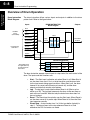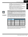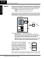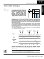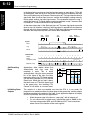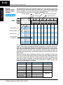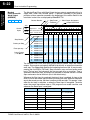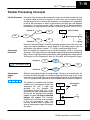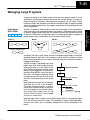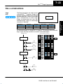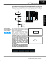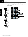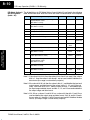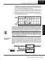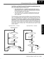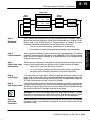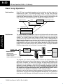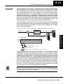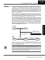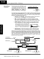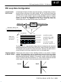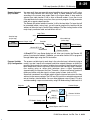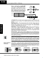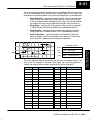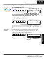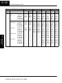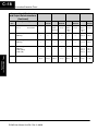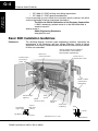
1
DL205 User Manual
Volume 2 of 2
D2–USER–M
1
Vol 2: Table of Contents
i
Chapter 6: Drum Instruction Programming
(DL250–1 / DL260 CPU only)
Introduction . . . . . . . . . . . . . . . . . . . . . . . . . . . . . . . . . . . . . . . . . . . . . . . . . . . . . . . . . . . . . . . . . . . . . . . . .
Purpose . . . . . . . . . . . . . . . . . . . . . . . . . . . . . . . . . . . . . . . . . . . . . . . . . . . . . . . . . . . . . . . . . . . . . . . . . .
Drum Terminology . . . . . . . . . . . . . . . . . . . . . . . . . . . . . . . . . . . . . . . . . . . . . . . . . . . . . . . . . . . . . . . . .
Drum Chart Representation . . . . . . . . . . . . . . . . . . . . . . . . . . . . . . . . . . . . . . . . . . . . . . . . . . . . . . . . .
Output Sequences . . . . . . . . . . . . . . . . . . . . . . . . . . . . . . . . . . . . . . . . . . . . . . . . . . . . . . . . . . . . . . . .
Step Transitions . . . . . . . . . . . . . . . . . . . . . . . . . . . . . . . . . . . . . . . . . . . . . . . . . . . . . . . . . . . . . . . . . . . . .
Drum Instruction Types . . . . . . . . . . . . . . . . . . . . . . . . . . . . . . . . . . . . . . . . . . . . . . . . . . . . . . . . . . . .
Timer-Only Transitions . . . . . . . . . . . . . . . . . . . . . . . . . . . . . . . . . . . . . . . . . . . . . . . . . . . . . . . . . . . . .
Timer and Event Transitions . . . . . . . . . . . . . . . . . . . . . . . . . . . . . . . . . . . . . . . . . . . . . . . . . . . . . . . .
Event-Only Transitions . . . . . . . . . . . . . . . . . . . . . . . . . . . . . . . . . . . . . . . . . . . . . . . . . . . . . . . . . . . . .
Counter Assignments . . . . . . . . . . . . . . . . . . . . . . . . . . . . . . . . . . . . . . . . . . . . . . . . . . . . . . . . . . . . . .
Last Step Completion . . . . . . . . . . . . . . . . . . . . . . . . . . . . . . . . . . . . . . . . . . . . . . . . . . . . . . . . . . . . . .
Overview of Drum Operation . . . . . . . . . . . . . . . . . . . . . . . . . . . . . . . . . . . . . . . . . . . . . . . . . . . . . . . . .
Drum Instruction Block Diagram . . . . . . . . . . . . . . . . . . . . . . . . . . . . . . . . . . . . . . . . . . . . . . . . . . . . .
Powerup State of Drum Registers . . . . . . . . . . . . . . . . . . . . . . . . . . . . . . . . . . . . . . . . . . . . . . . . . . .
Output Mask Operation . . . . . . . . . . . . . . . . . . . . . . . . . . . . . . . . . . . . . . . . . . . . . . . . . . . . . . . . . . . .
Drum Control Techniques . . . . . . . . . . . . . . . . . . . . . . . . . . . . . . . . . . . . . . . . . . . . . . . . . . . . . . . . . . . .
Drum Control Inputs . . . . . . . . . . . . . . . . . . . . . . . . . . . . . . . . . . . . . . . . . . . . . . . . . . . . . . . . . . . . . . .
Self-Resetting Drum . . . . . . . . . . . . . . . . . . . . . . . . . . . . . . . . . . . . . . . . . . . . . . . . . . . . . . . . . . . . . . .
Initializing Drum Outputs . . . . . . . . . . . . . . . . . . . . . . . . . . . . . . . . . . . . . . . . . . . . . . . . . . . . . . . . . . .
Cascaded Drums Provide More Than 16 Steps . . . . . . . . . . . . . . . . . . . . . . . . . . . . . . . . . . . . . . . .
Drum Instructions . . . . . . . . . . . . . . . . . . . . . . . . . . . . . . . . . . . . . . . . . . . . . . . . . . . . . . . . . . . . . . . . . . .
Timed Drum with Discrete Outputs (DRUM) . . . . . . . . . . . . . . . . . . . . . . . . . . . . . . . . . . . . . . . . . . .
Event Drum with Discrete Outputs (EDRUM) . . . . . . . . . . . . . . . . . . . . . . . . . . . . . . . . . . . . . . . . . .
Masked Event Drum with Discrete Outputs (MDRMD) . . . . . . . . . . . . . . . . . . . . . . . . . . . . . . . . . .
Masked Event Drum with Word Output (MDRMW) . . . . . . . . . . . . . . . . . . . . . . . . . . . . . . . . . . . . .
6–2
6–2
6–2
6–3
6–3
6–4
6–4
6–4
6–5
6–6
6–6
6–7
6–8
6–8
6–9
6–10
6–11
6–11
6–12
6–12
6–13
6–14
6–14
6–16
6–20
6–22
Chapter 7: RLLPLUS Stage Programming
Introduction to Stage Programming . . . . . . . . . . . . . . . . . . . . . . . . . . . . . . . . . . . . . . . . . . . . . . . . . . .
Overcoming “Stage Fright” . . . . . . . . . . . . . . . . . . . . . . . . . . . . . . . . . . . . . . . . . . . . . . . . . . . . . . . . .
Learning to Draw State Transition Diagrams . . . . . . . . . . . . . . . . . . . . . . . . . . . . . . . . . . . . . . . . . . .
Introduction to Process States . . . . . . . . . . . . . . . . . . . . . . . . . . . . . . . . . . . . . . . . . . . . . . . . . . . . . .
The Need for State Diagrams . . . . . . . . . . . . . . . . . . . . . . . . . . . . . . . . . . . . . . . . . . . . . . . . . . . . . . .
A 2–State Process . . . . . . . . . . . . . . . . . . . . . . . . . . . . . . . . . . . . . . . . . . . . . . . . . . . . . . . . . . . . . . . .
RLL Equivalent . . . . . . . . . . . . . . . . . . . . . . . . . . . . . . . . . . . . . . . . . . . . . . . . . . . . . . . . . . . . . . . . . . .
Stage Equivalent . . . . . . . . . . . . . . . . . . . . . . . . . . . . . . . . . . . . . . . . . . . . . . . . . . . . . . . . . . . . . . . . . .
7–2
7–2
7–3
7–3
7–3
7–3
7–4
7–4
ii
Table of Contents
Let’s Compare . . . . . . . . . . . . . . . . . . . . . . . . . . . . . . . . . . . . . . . . . . . . . . . . . . . . . . . . . . . . . . . . . . . .
Initial Stages . . . . . . . . . . . . . . . . . . . . . . . . . . . . . . . . . . . . . . . . . . . . . . . . . . . . . . . . . . . . . . . . . . . . . .
What Stage Bits Do . . . . . . . . . . . . . . . . . . . . . . . . . . . . . . . . . . . . . . . . . . . . . . . . . . . . . . . . . . . . . . . .
Stage Instruction Characteristics . . . . . . . . . . . . . . . . . . . . . . . . . . . . . . . . . . . . . . . . . . . . . . . . . . . .
Using the Stage Jump Instruction for State Transitions . . . . . . . . . . . . . . . . . . . . . . . . . . . . . . . .
Stage Jump, Set, and Reset Instructions . . . . . . . . . . . . . . . . . . . . . . . . . . . . . . . . . . . . . . . . . . . . .
Stage Program Example: Toggle On/Off Lamp Controller . . . . . . . . . . . . . . . . . . . . . . . . . . . . . . .
A 4–State Process . . . . . . . . . . . . . . . . . . . . . . . . . . . . . . . . . . . . . . . . . . . . . . . . . . . . . . . . . . . . . . . .
Four Steps to Writing a Stage Program . . . . . . . . . . . . . . . . . . . . . . . . . . . . . . . . . . . . . . . . . . . . . . .
7–5
7–5
7–6
7–6
7–7
7–7
7–8
7–8
7–9
Stage Program Example: A Garage Door Opener . . . . . . . . . . . . . . . . . . . . . . . . . . . . . . . . . . . . . .
Garage Door Opener Example . . . . . . . . . . . . . . . . . . . . . . . . . . . . . . . . . . . . . . . . . . . . . . . . . . . . . .
Draw the Block Diagram . . . . . . . . . . . . . . . . . . . . . . . . . . . . . . . . . . . . . . . . . . . . . . . . . . . . . . . . . . .
Draw the State Diagram . . . . . . . . . . . . . . . . . . . . . . . . . . . . . . . . . . . . . . . . . . . . . . . . . . . . . . . . . . . .
Add Safety Light Feature . . . . . . . . . . . . . . . . . . . . . . . . . . . . . . . . . . . . . . . . . . . . . . . . . . . . . . . . . . .
Modify the Block Diagram and State Diagram . . . . . . . . . . . . . . . . . . . . . . . . . . . . . . . . . . . . . . . . .
Using a Timer Inside a Stage . . . . . . . . . . . . . . . . . . . . . . . . . . . . . . . . . . . . . . . . . . . . . . . . . . . . . . .
Add Emergency Stop Feature . . . . . . . . . . . . . . . . . . . . . . . . . . . . . . . . . . . . . . . . . . . . . . . . . . . . . . .
Exclusive Transitions . . . . . . . . . . . . . . . . . . . . . . . . . . . . . . . . . . . . . . . . . . . . . . . . . . . . . . . . . . . . . .
Stage Program Design Considerations . . . . . . . . . . . . . . . . . . . . . . . . . . . . . . . . . . . . . . . . . . . . . . . .
Stage Program Organization . . . . . . . . . . . . . . . . . . . . . . . . . . . . . . . . . . . . . . . . . . . . . . . . . . . . . . . .
How Instructions Work Inside Stages . . . . . . . . . . . . . . . . . . . . . . . . . . . . . . . . . . . . . . . . . . . . . . . .
Using a Stage as a Supervisory Process . . . . . . . . . . . . . . . . . . . . . . . . . . . . . . . . . . . . . . . . . . . . .
Stage Counter . . . . . . . . . . . . . . . . . . . . . . . . . . . . . . . . . . . . . . . . . . . . . . . . . . . . . . . . . . . . . . . . . . . .
Unconditional Outputs . . . . . . . . . . . . . . . . . . . . . . . . . . . . . . . . . . . . . . . . . . . . . . . . . . . . . . . . . . . . .
Power Flow Transition Technique . . . . . . . . . . . . . . . . . . . . . . . . . . . . . . . . . . . . . . . . . . . . . . . . . . . .
Parallel Processing Concepts . . . . . . . . . . . . . . . . . . . . . . . . . . . . . . . . . . . . . . . . . . . . . . . . . . . . . . . .
Parallel Processes . . . . . . . . . . . . . . . . . . . . . . . . . . . . . . . . . . . . . . . . . . . . . . . . . . . . . . . . . . . . . . . .
Converging Processes . . . . . . . . . . . . . . . . . . . . . . . . . . . . . . . . . . . . . . . . . . . . . . . . . . . . . . . . . . . . .
Convergence Stages (CV) . . . . . . . . . . . . . . . . . . . . . . . . . . . . . . . . . . . . . . . . . . . . . . . . . . . . . . . . . .
Convergence Jump (CVJMP) . . . . . . . . . . . . . . . . . . . . . . . . . . . . . . . . . . . . . . . . . . . . . . . . . . . . . . .
Convergence Stage Guidelines . . . . . . . . . . . . . . . . . . . . . . . . . . . . . . . . . . . . . . . . . . . . . . . . . . . . .
Managing Large Programs . . . . . . . . . . . . . . . . . . . . . . . . . . . . . . . . . . . . . . . . . . . . . . . . . . . . . . . . . . .
Stage Blocks (BLK, BEND) . . . . . . . . . . . . . . . . . . . . . . . . . . . . . . . . . . . . . . . . . . . . . . . . . . . . . . . . .
Block Call (BCALL) . . . . . . . . . . . . . . . . . . . . . . . . . . . . . . . . . . . . . . . . . . . . . . . . . . . . . . . . . . . . . . . .
RLLPLUS Instructions . . . . . . . . . . . . . . . . . . . . . . . . . . . . . . . . . . . . . . . . . . . . . . . . . . . . . . . . . . . . . . .
Stage (SG) . . . . . . . . . . . . . . . . . . . . . . . . . . . . . . . . . . . . . . . . . . . . . . . . . . . . . . . . . . . . . . . . . . . . . . .
Initial Stage (ISG) . . . . . . . . . . . . . . . . . . . . . . . . . . . . . . . . . . . . . . . . . . . . . . . . . . . . . . . . . . . . . . . . .
Jump (JMP) . . . . . . . . . . . . . . . . . . . . . . . . . . . . . . . . . . . . . . . . . . . . . . . . . . . . . . . . . . . . . . . . . . . . . .
Not Jump (NJMP) . . . . . . . . . . . . . . . . . . . . . . . . . . . . . . . . . . . . . . . . . . . . . . . . . . . . . . . . . . . . . . . . .
Converge Stage (CV) and Converge Jump (CVJMP) . . . . . . . . . . . . . . . . . . . . . . . . . . . . . . . . . . .
Block Call (BCALL) . . . . . . . . . . . . . . . . . . . . . . . . . . . . . . . . . . . . . . . . . . . . . . . . . . . . . . . . . . . . . . . .
Block (BLK) . . . . . . . . . . . . . . . . . . . . . . . . . . . . . . . . . . . . . . . . . . . . . . . . . . . . . . . . . . . . . . . . . . . . . .
Block End (BEND) . . . . . . . . . . . . . . . . . . . . . . . . . . . . . . . . . . . . . . . . . . . . . . . . . . . . . . . . . . . . . . . . .
Stage View in DirectSOFT32 . . . . . . . . . . . . . . . . . . . . . . . . . . . . . . . . . . . . . . . . . . . . . . . . . . . . . . .
Questions and Answers about Stage Programming . . . . . . . . . . . . . . . . . . . . . . . . . . . . . . . . . . . .
7–10
7–10
7–10
7–11
7–12
7–12
7–13
7–14
7–14
7–15
7–15
7–16
7–17
7–17
7–18
7–18
7–19
7–19
7–19
7–19
7–20
7–20
7–21
7–21
7–22
7–23
7–23
7–24
7–24
7–24
7–25
7–27
7–27
7–27
7–28
7–29
iii
Table of Contents
Chapter 8: PID Loop Operation (DL250–1 and DL260 only)
DL250–1 and DL260 PID Loop Features . . . . . . . . . . . . . . . . . . . . . . . . . . . . . . . . . . . . . . . . . . . . . . .
Main Features . . . . . . . . . . . . . . . . . . . . . . . . . . . . . . . . . . . . . . . . . . . . . . . . . . . . . . . . . . . . . . . . . . . .
Getting Acquainted with PID Loops . . . . . . . . . . . . . . . . . . . . . . . . . . . . . . . . . . . . . . . . . . . . . . . . . .
Loop Setup Parameters . . . . . . . . . . . . . . . . . . . . . . . . . . . . . . . . . . . . . . . . . . . . . . . . . . . . . . . . . . . . . .
Loop Table and Number of Loops . . . . . . . . . . . . . . . . . . . . . . . . . . . . . . . . . . . . . . . . . . . . . . . . . . .
PID Error Flags . . . . . . . . . . . . . . . . . . . . . . . . . . . . . . . . . . . . . . . . . . . . . . . . . . . . . . . . . . . . . . . . . . .
Establishing the Loop Table Size and Location . . . . . . . . . . . . . . . . . . . . . . . . . . . . . . . . . . . . . . . .
Loop Table Word Definitions . . . . . . . . . . . . . . . . . . . . . . . . . . . . . . . . . . . . . . . . . . . . . . . . . . . . . . . .
PID Mode Setting 1 Bit Descriptions (Addr + 00) . . . . . . . . . . . . . . . . . . . . . . . . . . . . . . . . . . . . . . .
PID Mode Setting 2 Bit Descriptions (Addr + 01) . . . . . . . . . . . . . . . . . . . . . . . . . . . . . . . . . . . . . . .
Mode / Alarm Monitoring Word (Addr + 06) . . . . . . . . . . . . . . . . . . . . . . . . . . . . . . . . . . . . . . . . . . .
Ramp / Soak Table Flags (Addr + 33) . . . . . . . . . . . . . . . . . . . . . . . . . . . . . . . . . . . . . . . . . . . . . . . .
Ramp/Soak Table Location (Addr + 34) . . . . . . . . . . . . . . . . . . . . . . . . . . . . . . . . . . . . . . . . . . . . . .
Ramp/Soak Table Programming Error Flags (Addr + 35) . . . . . . . . . . . . . . . . . . . . . . . . . . . . . . . .
PV Auto Transfer (Addr + 36) from I/O Module Base/Slot/Channel Option . . . . . . . . . . . . . . . . .
PV Auto Transfer (Addr + 36) from V–memory Option . . . . . . . . . . . . . . . . . . . . . . . . . . . . . . . . . .
Control Output Auto Transfer (Addr + 37) . . . . . . . . . . . . . . . . . . . . . . . . . . . . . . . . . . . . . . . . . . . . .
Loop Sample Rate and Scheduling . . . . . . . . . . . . . . . . . . . . . . . . . . . . . . . . . . . . . . . . . . . . . . . . . . .
Loop Sample Rates . . . . . . . . . . . . . . . . . . . . . . . . . . . . . . . . . . . . . . . . . . . . . . . . . . . . . . . . . . . . . . .
Choosing the Best Sample Rate . . . . . . . . . . . . . . . . . . . . . . . . . . . . . . . . . . . . . . . . . . . . . . . . . . . . .
Programming the Sample Rate . . . . . . . . . . . . . . . . . . . . . . . . . . . . . . . . . . . . . . . . . . . . . . . . . . . . . .
PID Loop Effect on CPU Scan Time . . . . . . . . . . . . . . . . . . . . . . . . . . . . . . . . . . . . . . . . . . . . . . . . .
Ten Steps to Successful Process Control . . . . . . . . . . . . . . . . . . . . . . . . . . . . . . . . . . . . . . . . . . . . .
Step 1: Know the Recipe . . . . . . . . . . . . . . . . . . . . . . . . . . . . . . . . . . . . . . . . . . . . . . . . . . . . . . . . . . .
Step 2: Plan Loop Control Strategy . . . . . . . . . . . . . . . . . . . . . . . . . . . . . . . . . . . . . . . . . . . . . . . . . .
Step 3: Size and Scale Loop Components . . . . . . . . . . . . . . . . . . . . . . . . . . . . . . . . . . . . . . . . . . . .
Step 4: Select I/O Modules . . . . . . . . . . . . . . . . . . . . . . . . . . . . . . . . . . . . . . . . . . . . . . . . . . . . . . . . .
Step 5: Wiring and Installation . . . . . . . . . . . . . . . . . . . . . . . . . . . . . . . . . . . . . . . . . . . . . . . . . . . . . .
Step 6: Loop Parameters . . . . . . . . . . . . . . . . . . . . . . . . . . . . . . . . . . . . . . . . . . . . . . . . . . . . . . . . . . .
Step 7: Check Open Loop Performance . . . . . . . . . . . . . . . . . . . . . . . . . . . . . . . . . . . . . . . . . . . . . .
Step 8: Loop Tuning . . . . . . . . . . . . . . . . . . . . . . . . . . . . . . . . . . . . . . . . . . . . . . . . . . . . . . . . . . . . . . .
Step 9: Run Process Cycle . . . . . . . . . . . . . . . . . . . . . . . . . . . . . . . . . . . . . . . . . . . . . . . . . . . . . . . . .
Step 10: Save Loop Parameters . . . . . . . . . . . . . . . . . . . . . . . . . . . . . . . . . . . . . . . . . . . . . . . . . . . .
Basic Loop Operation . . . . . . . . . . . . . . . . . . . . . . . . . . . . . . . . . . . . . . . . . . . . . . . . . . . . . . . . . . . . . . .
Data Locations . . . . . . . . . . . . . . . . . . . . . . . . . . . . . . . . . . . . . . . . . . . . . . . . . . . . . . . . . . . . . . . . . . . .
Data Sources . . . . . . . . . . . . . . . . . . . . . . . . . . . . . . . . . . . . . . . . . . . . . . . . . . . . . . . . . . . . . . . . . . . . .
Auto Transfer to Analog I/O . . . . . . . . . . . . . . . . . . . . . . . . . . . . . . . . . . . . . . . . . . . . . . . . . . . . . . . . .
Loop Modes . . . . . . . . . . . . . . . . . . . . . . . . . . . . . . . . . . . . . . . . . . . . . . . . . . . . . . . . . . . . . . . . . . . . . .
CPU Modes and Loop Modes . . . . . . . . . . . . . . . . . . . . . . . . . . . . . . . . . . . . . . . . . . . . . . . . . . . . . . .
How to Change Loop Modes . . . . . . . . . . . . . . . . . . . . . . . . . . . . . . . . . . . . . . . . . . . . . . . . . . . . . . . .
Operator Panel Control of PID Modes . . . . . . . . . . . . . . . . . . . . . . . . . . . . . . . . . . . . . . . . . . . . . . . .
PLC Modes’ Effect on Loop Modes . . . . . . . . . . . . . . . . . . . . . . . . . . . . . . . . . . . . . . . . . . . . . . . . . .
Loop Mode Override . . . . . . . . . . . . . . . . . . . . . . . . . . . . . . . . . . . . . . . . . . . . . . . . . . . . . . . . . . . . . . .
Bumpless Transfers . . . . . . . . . . . . . . . . . . . . . . . . . . . . . . . . . . . . . . . . . . . . . . . . . . . . . . . . . . . . . . .
PID Loop Data Configuration . . . . . . . . . . . . . . . . . . . . . . . . . . . . . . . . . . . . . . . . . . . . . . . . . . . . . . . . .
8–2
8–2
8–4
8–6
8–6
8–6
8–7
8–8
8–9
8–10
8–11
8–11
8–12
8–12
8–13
8–13
8–13
8–14
8–14
8–14
8–15
8–16
8–18
8–18
8–18
8–18
8–18
8–19
8–19
8–19
8–19
8–19
8–19
8–20
8–20
8–20
8–21
8–22
8–23
8–24
8–25
8–25
8–25
8–26
8–27
iv
Table of Contents
Loop Parameter Data Formats . . . . . . . . . . . . . . . . . . . . . . . . . . . . . . . . . . . . . . . . . . . . . . . . . . . . . .
Choosing Unipolar or Bipolar Format . . . . . . . . . . . . . . . . . . . . . . . . . . . . . . . . . . . . . . . . . . . . . . . . .
Handling Data Offsets . . . . . . . . . . . . . . . . . . . . . . . . . . . . . . . . . . . . . . . . . . . . . . . . . . . . . . . . . . . . .
Setpoint (SP) Location . . . . . . . . . . . . . . . . . . . . . . . . . . . . . . . . . . . . . . . . . . . . . . . . . . . . . . . . . . . . .
Remote Setpoint (SP) Location . . . . . . . . . . . . . . . . . . . . . . . . . . . . . . . . . . . . . . . . . . . . . . . . . . . . .
Process Variable (PV) Configuration . . . . . . . . . . . . . . . . . . . . . . . . . . . . . . . . . . . . . . . . . . . . . . . . .
Control Output Configuration . . . . . . . . . . . . . . . . . . . . . . . . . . . . . . . . . . . . . . . . . . . . . . . . . . . . . . . .
Error Term Configuration . . . . . . . . . . . . . . . . . . . . . . . . . . . . . . . . . . . . . . . . . . . . . . . . . . . . . . . . . . .
PID Algorithms . . . . . . . . . . . . . . . . . . . . . . . . . . . . . . . . . . . . . . . . . . . . . . . . . . . . . . . . . . . . . . . . . . . . . .
Position Algorithm . . . . . . . . . . . . . . . . . . . . . . . . . . . . . . . . . . . . . . . . . . . . . . . . . . . . . . . . . . . . . . . . .
Velocity Algorithm . . . . . . . . . . . . . . . . . . . . . . . . . . . . . . . . . . . . . . . . . . . . . . . . . . . . . . . . . . . . . . . . .
Direct-Acting and Reverse-Acting Loops . . . . . . . . . . . . . . . . . . . . . . . . . . . . . . . . . . . . . . . . . . . . .
P-I-D Loop Terms . . . . . . . . . . . . . . . . . . . . . . . . . . . . . . . . . . . . . . . . . . . . . . . . . . . . . . . . . . . . . . . . .
Using a Subset of PID Control . . . . . . . . . . . . . . . . . . . . . . . . . . . . . . . . . . . . . . . . . . . . . . . . . . . . . .
Derivative Gain Limiting . . . . . . . . . . . . . . . . . . . . . . . . . . . . . . . . . . . . . . . . . . . . . . . . . . . . . . . . . . . .
Bias Term . . . . . . . . . . . . . . . . . . . . . . . . . . . . . . . . . . . . . . . . . . . . . . . . . . . . . . . . . . . . . . . . . . . . . . . .
Bias Freeze . . . . . . . . . . . . . . . . . . . . . . . . . . . . . . . . . . . . . . . . . . . . . . . . . . . . . . . . . . . . . . . . . . . . . .
Loop Tuning Procedure . . . . . . . . . . . . . . . . . . . . . . . . . . . . . . . . . . . . . . . . . . . . . . . . . . . . . . . . . . . . . .
Open-Loop Test . . . . . . . . . . . . . . . . . . . . . . . . . . . . . . . . . . . . . . . . . . . . . . . . . . . . . . . . . . . . . . . . . . .
Manual Tuning Procedure . . . . . . . . . . . . . . . . . . . . . . . . . . . . . . . . . . . . . . . . . . . . . . . . . . . . . . . . . .
Auto Tuning Procedure . . . . . . . . . . . . . . . . . . . . . . . . . . . . . . . . . . . . . . . . . . . . . . . . . . . . . . . . . . . .
Tuning Cascaded Loops . . . . . . . . . . . . . . . . . . . . . . . . . . . . . . . . . . . . . . . . . . . . . . . . . . . . . . . . . . .
PV Analog Filter . . . . . . . . . . . . . . . . . . . . . . . . . . . . . . . . . . . . . . . . . . . . . . . . . . . . . . . . . . . . . . . . . . . . .
PV Auto Transfer Functions with Filtering Options . . . . . . . . . . . . . . . . . . . . . . . . . . . . . . . . . . . . .
Creating an Analog Filter in Ladder Logic . . . . . . . . . . . . . . . . . . . . . . . . . . . . . . . . . . . . . . . . . . . . .
Feedforward Control . . . . . . . . . . . . . . . . . . . . . . . . . . . . . . . . . . . . . . . . . . . . . . . . . . . . . . . . . . . . . . . . .
Feedforward Example . . . . . . . . . . . . . . . . . . . . . . . . . . . . . . . . . . . . . . . . . . . . . . . . . . . . . . . . . . . . .
Time-Proportioning Control . . . . . . . . . . . . . . . . . . . . . . . . . . . . . . . . . . . . . . . . . . . . . . . . . . . . . . . . . .
On/Off Control Program Example . . . . . . . . . . . . . . . . . . . . . . . . . . . . . . . . . . . . . . . . . . . . . . . . . . . .
Cascade Control . . . . . . . . . . . . . . . . . . . . . . . . . . . . . . . . . . . . . . . . . . . . . . . . . . . . . . . . . . . . . . . . . . . .
Introduction . . . . . . . . . . . . . . . . . . . . . . . . . . . . . . . . . . . . . . . . . . . . . . . . . . . . . . . . . . . . . . . . . . . . . . .
Cascaded Loops in the DL250–1, DL260 CPUs . . . . . . . . . . . . . . . . . . . . . . . . . . . . . . . . . . . . . . .
Process Alarms . . . . . . . . . . . . . . . . . . . . . . . . . . . . . . . . . . . . . . . . . . . . . . . . . . . . . . . . . . . . . . . . . . . . .
PV Absolute Value Alarms . . . . . . . . . . . . . . . . . . . . . . . . . . . . . . . . . . . . . . . . . . . . . . . . . . . . . . . . . .
PV Deviation Alarms . . . . . . . . . . . . . . . . . . . . . . . . . . . . . . . . . . . . . . . . . . . . . . . . . . . . . . . . . . . . . . .
PV Rate-of-Change Alarm . . . . . . . . . . . . . . . . . . . . . . . . . . . . . . . . . . . . . . . . . . . . . . . . . . . . . . . . . .
PV Alarm Hysteresis . . . . . . . . . . . . . . . . . . . . . . . . . . . . . . . . . . . . . . . . . . . . . . . . . . . . . . . . . . . . . . .
Alarm Programing Error . . . . . . . . . . . . . . . . . . . . . . . . . . . . . . . . . . . . . . . . . . . . . . . . . . . . . . . . . . . .
Ramp/Soak Generator . . . . . . . . . . . . . . . . . . . . . . . . . . . . . . . . . . . . . . . . . . . . . . . . . . . . . . . . . . . . . . .
Introduction . . . . . . . . . . . . . . . . . . . . . . . . . . . . . . . . . . . . . . . . . . . . . . . . . . . . . . . . . . . . . . . . . . . . . . .
Ramp/Soak Table . . . . . . . . . . . . . . . . . . . . . . . . . . . . . . . . . . . . . . . . . . . . . . . . . . . . . . . . . . . . . . . . .
Ramp / Soak Table Flags . . . . . . . . . . . . . . . . . . . . . . . . . . . . . . . . . . . . . . . . . . . . . . . . . . . . . . . . . . .
Ramp/Soak Generator Enable . . . . . . . . . . . . . . . . . . . . . . . . . . . . . . . . . . . . . . . . . . . . . . . . . . . . . .
Ramp/Soak Controls . . . . . . . . . . . . . . . . . . . . . . . . . . . . . . . . . . . . . . . . . . . . . . . . . . . . . . . . . . . . . . .
Ramp/Soak Profile Monitoring . . . . . . . . . . . . . . . . . . . . . . . . . . . . . . . . . . . . . . . . . . . . . . . . . . . . . .
Ramp/Soak Programming Errors . . . . . . . . . . . . . . . . . . . . . . . . . . . . . . . . . . . . . . . . . . . . . . . . . . . .
8–27
8–27
8–28
8–28
8–29
8–29
8–30
8–31
8–32
8–32
8–33
8–34
8–35
8–36
8–37
8–37
8–38
8–39
8–39
8–40
8–41
8–45
8–46
8–47
8–48
8–49
8–50
8–51
8–52
8–53
8–53
8–54
8–55
8–56
8–56
8–57
8–58
8–58
8–59
8–59
8–60
8–62
8–62
8–62
8–63
8–63
v
Table of Contents
Testing Your Ramp/Soak Profile . . . . . . . . . . . . . . . . . . . . . . . . . . . . . . . . . . . . . . . . . . . . . . . . . . . . .
Troubleshooting Tips . . . . . . . . . . . . . . . . . . . . . . . . . . . . . . . . . . . . . . . . . . . . . . . . . . . . . . . . . . . . . . . .
8–63
8–64
Bibliography . . . . . . . . . . . . . . . . . . . . . . . . . . . . . . . . . . . . . . . . . . . . . . . . . . . . . . . . . . . . . . . . . . . . . . . .
8–65
Glossary of PID Loop Terminology . . . . . . . . . . . . . . . . . . . . . . . . . . . . . . . . . . . . . . . . . . . . . . . . . . .
8–66
Chapter 9: Maintenance and Troubleshooting
Hardware Maintenance . . . . . . . . . . . . . . . . . . . . . . . . . . . . . . . . . . . . . . . . . . . . . . . . . . . . . . . . . . . . . .
9–2
Diagnostics . . . . . . . . . . . . . . . . . . . . . . . . . . . . . . . . . . . . . . . . . . . . . . . . . . . . . . . . . . . . . . . . . . . . . . . . .
9–3
CPU Indicators . . . . . . . . . . . . . . . . . . . . . . . . . . . . . . . . . . . . . . . . . . . . . . . . . . . . . . . . . . . . . . . . . . . . . .
9–10
PWR Indicator . . . . . . . . . . . . . . . . . . . . . . . . . . . . . . . . . . . . . . . . . . . . . . . . . . . . . . . . . . . . . . . . . . . . . . .
9–11
RUN Indicator . . . . . . . . . . . . . . . . . . . . . . . . . . . . . . . . . . . . . . . . . . . . . . . . . . . . . . . . . . . . . . . . . . . . . . .
9–13
CPU Indicator . . . . . . . . . . . . . . . . . . . . . . . . . . . . . . . . . . . . . . . . . . . . . . . . . . . . . . . . . . . . . . . . . . . . . . .
9–13
BATT Indicator . . . . . . . . . . . . . . . . . . . . . . . . . . . . . . . . . . . . . . . . . . . . . . . . . . . . . . . . . . . . . . . . . . . . . .
9–13
Communications Problems . . . . . . . . . . . . . . . . . . . . . . . . . . . . . . . . . . . . . . . . . . . . . . . . . . . . . . . . . .
9–13
I/O Module Troubleshooting . . . . . . . . . . . . . . . . . . . . . . . . . . . . . . . . . . . . . . . . . . . . . . . . . . . . . . . . . .
9–14
Noise Troubleshooting . . . . . . . . . . . . . . . . . . . . . . . . . . . . . . . . . . . . . . . . . . . . . . . . . . . . . . . . . . . . . . .
9–17
Machine Startup and Program Troubleshooting . . . . . . . . . . . . . . . . . . . . . . . . . . . . . . . . . . . . . . . .
9–18
Appendix A: Auxiliary Functions
Introduction . . . . . . . . . . . . . . . . . . . . . . . . . . . . . . . . . . . . . . . . . . . . . . . . . . . . . . . . . . . . . . . . . . . . . . .
What are Auxiliary Functions? . . . . . . . . . . . . . . . . . . . . . . . . . . . . . . . . . . . . . . . . . . . . . . . . . . . . . .
Accessing AUX Functions via DirectSOFT32 . . . . . . . . . . . . . . . . . . . . . . . . . . . . . . . . . . . . . . . . . .
Accessing AUX Functions via the Handheld Programmer . . . . . . . . . . . . . . . . . . . . . . . . . . . . . . .
AUX 2* — RLL Operations . . . . . . . . . . . . . . . . . . . . . . . . . . . . . . . . . . . . . . . . . . . . . . . . . . . . . . . . . . .
AUX 21, 22, 23 and 24 . . . . . . . . . . . . . . . . . . . . . . . . . . . . . . . . . . . . . . . . . . . . . . . . . . . . . . . . . . . . .
AUX 21 Check Program . . . . . . . . . . . . . . . . . . . . . . . . . . . . . . . . . . . . . . . . . . . . . . . . . . . . . . . . . . . .
AUX 22 Change Reference . . . . . . . . . . . . . . . . . . . . . . . . . . . . . . . . . . . . . . . . . . . . . . . . . . . . . . . . .
AUX 23 Clear Ladder Range . . . . . . . . . . . . . . . . . . . . . . . . . . . . . . . . . . . . . . . . . . . . . . . . . . . . . . . .
AUX 24 Clear Ladders . . . . . . . . . . . . . . . . . . . . . . . . . . . . . . . . . . . . . . . . . . . . . . . . . . . . . . . . . . . . .
AUX 3* — V-memory Operations . . . . . . . . . . . . . . . . . . . . . . . . . . . . . . . . . . . . . . . . . . . . . . . . . . . . . .
AUX 31 Clear V Memory . . . . . . . . . . . . . . . . . . . . . . . . . . . . . . . . . . . . . . . . . . . . . . . . . . . . . . . . . . .
AUX 4* — I/O Configuration . . . . . . . . . . . . . . . . . . . . . . . . . . . . . . . . . . . . . . . . . . . . . . . . . . . . . . . . . .
AUX 41 – 46 . . . . . . . . . . . . . . . . . . . . . . . . . . . . . . . . . . . . . . . . . . . . . . . . . . . . . . . . . . . . . . . . . . . . . .
AUX 41 Show I/O Configuration . . . . . . . . . . . . . . . . . . . . . . . . . . . . . . . . . . . . . . . . . . . . . . . . . . . . .
AUX 42 I/O Diagnostics . . . . . . . . . . . . . . . . . . . . . . . . . . . . . . . . . . . . . . . . . . . . . . . . . . . . . . . . . . . .
AUX 44 Power-up Configuration Check . . . . . . . . . . . . . . . . . . . . . . . . . . . . . . . . . . . . . . . . . . . . . .
AUX 45 Select Configuration . . . . . . . . . . . . . . . . . . . . . . . . . . . . . . . . . . . . . . . . . . . . . . . . . . . . . . . .
AUX 46 I/O Configuration . . . . . . . . . . . . . . . . . . . . . . . . . . . . . . . . . . . . . . . . . . . . . . . . . . . . . . . . . .
AUX 5* — CPU Configuration . . . . . . . . . . . . . . . . . . . . . . . . . . . . . . . . . . . . . . . . . . . . . . . . . . . . . . . . .
AUX 51 – 58 . . . . . . . . . . . . . . . . . . . . . . . . . . . . . . . . . . . . . . . . . . . . . . . . . . . . . . . . . . . . . . . . . . . . . .
A–2
A–2
A–3
A–3
A–4
A–4
A–4
A–4
A–4
A–4
A–4
A–4
A–5
A–5
A–5
A–5
A–5
A–5
A–6
A–7
A–7
vi
Table of Contents
AUX 51 Modify Program Name . . . . . . . . . . . . . . . . . . . . . . . . . . . . . . . . . . . . . . . . . . . . . . . . . . . . . .
AUX 52 Display /Change Calendar . . . . . . . . . . . . . . . . . . . . . . . . . . . . . . . . . . . . . . . . . . . . . . . . . .
AUX 53 Display Scan Time . . . . . . . . . . . . . . . . . . . . . . . . . . . . . . . . . . . . . . . . . . . . . . . . . . . . . . . . .
AUX 54 Initialize Scratchpad . . . . . . . . . . . . . . . . . . . . . . . . . . . . . . . . . . . . . . . . . . . . . . . . . . . . . . . .
AUX 55 Set Watchdog Timer . . . . . . . . . . . . . . . . . . . . . . . . . . . . . . . . . . . . . . . . . . . . . . . . . . . . . . .
AUX 56 CPU Network Address . . . . . . . . . . . . . . . . . . . . . . . . . . . . . . . . . . . . . . . . . . . . . . . . . . . . . .
AUX 57 Set Retentive Ranges . . . . . . . . . . . . . . . . . . . . . . . . . . . . . . . . . . . . . . . . . . . . . . . . . . . . . .
AUX 58 Test Operations . . . . . . . . . . . . . . . . . . . . . . . . . . . . . . . . . . . . . . . . . . . . . . . . . . . . . . . . . . . .
AUX 59 Bit Override . . . . . . . . . . . . . . . . . . . . . . . . . . . . . . . . . . . . . . . . . . . . . . . . . . . . . . . . . . . . . . .
AUX 5B Counter Interface Configuration . . . . . . . . . . . . . . . . . . . . . . . . . . . . . . . . . . . . . . . . . . . . .
AUX 5C Display Error History . . . . . . . . . . . . . . . . . . . . . . . . . . . . . . . . . . . . . . . . . . . . . . . . . . . . . . .
AUX 6* — Handheld Programmer Configuration . . . . . . . . . . . . . . . . . . . . . . . . . . . . . . . . . . . . . . .
AUX 61, 62 and 65 . . . . . . . . . . . . . . . . . . . . . . . . . . . . . . . . . . . . . . . . . . . . . . . . . . . . . . . . . . . . . . . .
AUX 61 Show Revision Numbers . . . . . . . . . . . . . . . . . . . . . . . . . . . . . . . . . . . . . . . . . . . . . . . . . . . .
AUX 62 Beeper On / Off . . . . . . . . . . . . . . . . . . . . . . . . . . . . . . . . . . . . . . . . . . . . . . . . . . . . . . . . . . . .
AUX 65 Run Self Diagnostics . . . . . . . . . . . . . . . . . . . . . . . . . . . . . . . . . . . . . . . . . . . . . . . . . . . . . . .
AUX 7* — EEPROM Operations . . . . . . . . . . . . . . . . . . . . . . . . . . . . . . . . . . . . . . . . . . . . . . . . . . . . . . .
AUX 71 – 76 . . . . . . . . . . . . . . . . . . . . . . . . . . . . . . . . . . . . . . . . . . . . . . . . . . . . . . . . . . . . . . . . . . . . . .
Transferrable Memory Areas . . . . . . . . . . . . . . . . . . . . . . . . . . . . . . . . . . . . . . . . . . . . . . . . . . . . . . . .
AUX 71 CPU to HPP EEPROM . . . . . . . . . . . . . . . . . . . . . . . . . . . . . . . . . . . . . . . . . . . . . . . . . . . . .
AUX 72 HPP EEPROM to CPU . . . . . . . . . . . . . . . . . . . . . . . . . . . . . . . . . . . . . . . . . . . . . . . . . . . . .
AUX 73 Compare HPP EEPROM to CPU . . . . . . . . . . . . . . . . . . . . . . . . . . . . . . . . . . . . . . . . . . . .
AUX 74 HPP EEPROM Blank Check . . . . . . . . . . . . . . . . . . . . . . . . . . . . . . . . . . . . . . . . . . . . . . . .
AUX 75 Erase HPP EEPROM . . . . . . . . . . . . . . . . . . . . . . . . . . . . . . . . . . . . . . . . . . . . . . . . . . . . . .
AUX 76 Show EEPROM Type . . . . . . . . . . . . . . . . . . . . . . . . . . . . . . . . . . . . . . . . . . . . . . . . . . . . . .
AUX 8* — Password Operations . . . . . . . . . . . . . . . . . . . . . . . . . . . . . . . . . . . . . . . . . . . . . . . . . . . . . .
AUX 81 – 83 . . . . . . . . . . . . . . . . . . . . . . . . . . . . . . . . . . . . . . . . . . . . . . . . . . . . . . . . . . . . . . . . . . . . . .
AUX 81 Modify Password . . . . . . . . . . . . . . . . . . . . . . . . . . . . . . . . . . . . . . . . . . . . . . . . . . . . . . . . . .
AUX 82 Unlock CPU . . . . . . . . . . . . . . . . . . . . . . . . . . . . . . . . . . . . . . . . . . . . . . . . . . . . . . . . . . . . . . .
AUX 83 Lock CPU . . . . . . . . . . . . . . . . . . . . . . . . . . . . . . . . . . . . . . . . . . . . . . . . . . . . . . . . . . . . . . . . .
A–7
A–7
A–7
A–8
A–8
A–8
A–9
A–9
A–10
A–10
A–11
A–12
A–12
A–12
A–12
A–12
A–13
A–13
A–13
A–13
A–13
A–13
A–13
A–13
A–13
A–14
A–14
A–14
A–14
A–14
Appendix B: DL205 Error Codes
Appendix C: Instruction Execution Times
Introduction . . . . . . . . . . . . . . . . . . . . . . . . . . . . . . . . . . . . . . . . . . . . . . . . . . . . . . . . . . . . . . . . . . . . . . . . .
V-Memory Data Registers . . . . . . . . . . . . . . . . . . . . . . . . . . . . . . . . . . . . . . . . . . . . . . . . . . . . . . . . . .
V-Memory Bit Registers . . . . . . . . . . . . . . . . . . . . . . . . . . . . . . . . . . . . . . . . . . . . . . . . . . . . . . . . . . . .
How to Read the Tables . . . . . . . . . . . . . . . . . . . . . . . . . . . . . . . . . . . . . . . . . . . . . . . . . . . . . . . . . . . .
Boolean Instructions . . . . . . . . . . . . . . . . . . . . . . . . . . . . . . . . . . . . . . . . . . . . . . . . . . . . . . . . . . . . . . . .
C–2
C–2
C–2
C–3
C–4
Comparative Boolean . . . . . . . . . . . . . . . . . . . . . . . . . . . . . . . . . . . . . . . . . . . . . . . . . . . . . . . . . . . . . . . .
C–5
Bit of Word Boolean Instructions . . . . . . . . . . . . . . . . . . . . . . . . . . . . . . . . . . . . . . . . . . . . . . . . . . . . . C–14
Immediate Instructions . . . . . . . . . . . . . . . . . . . . . . . . . . . . . . . . . . . . . . . . . . . . . . . . . . . . . . . . . . . . . . C–15
Timer, Counter, Shift Register Instructions . . . . . . . . . . . . . . . . . . . . . . . . . . . . . . . . . . . . . . . . . . . . C–16
vii
Table of Contents
Accumulator Data Instructions . . . . . . . . . . . . . . . . . . . . . . . . . . . . . . . . . . . . . . . . . . . . . . . . . . . . . . . C–17
Logical Instructions . . . . . . . . . . . . . . . . . . . . . . . . . . . . . . . . . . . . . . . . . . . . . . . . . . . . . . . . . . . . . . . . . C–19
Math Instructions . . . . . . . . . . . . . . . . . . . . . . . . . . . . . . . . . . . . . . . . . . . . . . . . . . . . . . . . . . . . . . . . . . . . C–21
Differential Instructions . . . . . . . . . . . . . . . . . . . . . . . . . . . . . . . . . . . . . . . . . . . . . . . . . . . . . . . . . . . . . . C–24
Bit Instructions . . . . . . . . . . . . . . . . . . . . . . . . . . . . . . . . . . . . . . . . . . . . . . . . . . . . . . . . . . . . . . . . . . . . . . C–25
Number Conversion Instructions . . . . . . . . . . . . . . . . . . . . . . . . . . . . . . . . . . . . . . . . . . . . . . . . . . . . . C–26
Table Instructions . . . . . . . . . . . . . . . . . . . . . . . . . . . . . . . . . . . . . . . . . . . . . . . . . . . . . . . . . . . . . . . . . . . C–27
CPU Control Instructions . . . . . . . . . . . . . . . . . . . . . . . . . . . . . . . . . . . . . . . . . . . . . . . . . . . . . . . . . . . . C–29
Program Control Instructions . . . . . . . . . . . . . . . . . . . . . . . . . . . . . . . . . . . . . . . . . . . . . . . . . . . . . . . . C–29
Interrupt Instructions . . . . . . . . . . . . . . . . . . . . . . . . . . . . . . . . . . . . . . . . . . . . . . . . . . . . . . . . . . . . . . . . C–30
Network Instructions . . . . . . . . . . . . . . . . . . . . . . . . . . . . . . . . . . . . . . . . . . . . . . . . . . . . . . . . . . . . . . . . C–30
Intelligent I/O Instructions . . . . . . . . . . . . . . . . . . . . . . . . . . . . . . . . . . . . . . . . . . . . . . . . . . . . . . . . . . . C–30
Message Instructions . . . . . . . . . . . . . . . . . . . . . . . . . . . . . . . . . . . . . . . . . . . . . . . . . . . . . . . . . . . . . . . . C–31
RLLPLUS Instructions . . . . . . . . . . . . . . . . . . . . . . . . . . . . . . . . . . . . . . . . . . . . . . . . . . . . . . . . . . . . . . . C–31
DRUM Instructions . . . . . . . . . . . . . . . . . . . . . . . . . . . . . . . . . . . . . . . . . . . . . . . . . . . . . . . . . . . . . . . . . . C–32
Clock / Calander Instructions . . . . . . . . . . . . . . . . . . . . . . . . . . . . . . . . . . . . . . . . . . . . . . . . . . . . . . . . . C–32
MODBUS Instructions . . . . . . . . . . . . . . . . . . . . . . . . . . . . . . . . . . . . . . . . . . . . . . . . . . . . . . . . . . . . . . . C–32
ASCII Instructions . . . . . . . . . . . . . . . . . . . . . . . . . . . . . . . . . . . . . . . . . . . . . . . . . . . . . . . . . . . . . . . . . . . C–33
Appendix D: Special Relays
DL230 CPU Special Relays . . . . . . . . . . . . . . . . . . . . . . . . . . . . . . . . . . . . . . . . . . . . . . . . . . . . . . . . . . .
Startup and Real-Time Relays . . . . . . . . . . . . . . . . . . . . . . . . . . . . . . . . . . . . . . . . . . . . . . . . . . . . . .
CPU Status Relays . . . . . . . . . . . . . . . . . . . . . . . . . . . . . . . . . . . . . . . . . . . . . . . . . . . . . . . . . . . . . . . .
System Monitoring . . . . . . . . . . . . . . . . . . . . . . . . . . . . . . . . . . . . . . . . . . . . . . . . . . . . . . . . . . . . . . . .
Accumulator Status . . . . . . . . . . . . . . . . . . . . . . . . . . . . . . . . . . . . . . . . . . . . . . . . . . . . . . . . . . . . . . . .
Counter Interface Module Relays . . . . . . . . . . . . . . . . . . . . . . . . . . . . . . . . . . . . . . . . . . . . . . . . . . . .
Equal Relays for Multi-step Presets with Up/Down Counter #1
(for Counter Interface Module) . . . . . . . . . . . . . . . . . . . . . . . . . . . . . . . . . . . . . . . . . . . . . . . . . . .
DL240/DL250–1/DL260 CPU Special Relays . . . . . . . . . . . . . . . . . . . . . . . . . . . . . . . . . . . . . . . . . . . .
Startup and Real-Time Relays . . . . . . . . . . . . . . . . . . . . . . . . . . . . . . . . . . . . . . . . . . . . . . . . . . . . . .
CPU Status Relays . . . . . . . . . . . . . . . . . . . . . . . . . . . . . . . . . . . . . . . . . . . . . . . . . . . . . . . . . . . . . . . .
System Monitoring Relays . . . . . . . . . . . . . . . . . . . . . . . . . . . . . . . . . . . . . . . . . . . . . . . . . . . . . . . . . .
Accumulator Status Relays . . . . . . . . . . . . . . . . . . . . . . . . . . . . . . . . . . . . . . . . . . . . . . . . . . . . . . . . .
Counter Interface Module Relays . . . . . . . . . . . . . . . . . . . . . . . . . . . . . . . . . . . . . . . . . . . . . . . . . . . .
Communications Monitoring Relays . . . . . . . . . . . . . . . . . . . . . . . . . . . . . . . . . . . . . . . . . . . . . . . . . .
Equal Relays for Multi-step Presets with Up/Down Counter #1
(for Counter Interface Module) . . . . . . . . . . . . . . . . . . . . . . . . . . . . . . . . . . . . . . . . . . . . . . . . . . .
Equal Relays for Multi-step Presets with Up/Down Counter #2
(for Counter Interface Module) . . . . . . . . . . . . . . . . . . . . . . . . . . . . . . . . . . . . . . . . . . . . . . . . . . .
D–2
D–2
D–2
D–2
D–3
D–3
D–3
D–4
D–4
D–4
D–5
D–5
D–5
D–6
D–7
D–8
viii
Table of Contents
Appendix E: DL205 Product Weights
Product Weight Table . . . . . . . . . . . . . . . . . . . . . . . . . . . . . . . . . . . . . . . . . . . . . . . . . . . . . . . . . . . . . . . .
E–2
Appendix F: PLC Memory
DL205 PLC Memory . . . . . . . . . . . . . . . . . . . . . . . . . . . . . . . . . . . . . . . . . . . . . . . . . . . . . . . . . . . . . . . . .
F–2
Appendix G: European Union Directives (CE)
European Union (EU) Directives . . . . . . . . . . . . . . . . . . . . . . . . . . . . . . . . . . . . . . . . . . . . . . . . . . . . . .
Member Countries . . . . . . . . . . . . . . . . . . . . . . . . . . . . . . . . . . . . . . . . . . . . . . . . . . . . . . . . . . . . . . . . .
Special Installation Manual . . . . . . . . . . . . . . . . . . . . . . . . . . . . . . . . . . . . . . . . . . . . . . . . . . . . . . . . .
Other Sources of Information . . . . . . . . . . . . . . . . . . . . . . . . . . . . . . . . . . . . . . . . . . . . . . . . . . . . . . .
Basic EMC Installation Guidelines . . . . . . . . . . . . . . . . . . . . . . . . . . . . . . . . . . . . . . . . . . . . . . . . . . . .
Enclosures . . . . . . . . . . . . . . . . . . . . . . . . . . . . . . . . . . . . . . . . . . . . . . . . . . . . . . . . . . . . . . . . . . . . . . .
Electrostatic Discharge (ESD) . . . . . . . . . . . . . . . . . . . . . . . . . . . . . . . . . . . . . . . . . . . . . . . . . . . . . . .
Suppression and Fusing . . . . . . . . . . . . . . . . . . . . . . . . . . . . . . . . . . . . . . . . . . . . . . . . . . . . . . . . . . .
Internal Enclosure Grounding . . . . . . . . . . . . . . . . . . . . . . . . . . . . . . . . . . . . . . . . . . . . . . . . . . . . . . .
Equi–potential Grounding . . . . . . . . . . . . . . . . . . . . . . . . . . . . . . . . . . . . . . . . . . . . . . . . . . . . . . . . . .
Communications and Shielded Cables . . . . . . . . . . . . . . . . . . . . . . . . . . . . . . . . . . . . . . . . . . . . . . .
Analog and RS232 Cables . . . . . . . . . . . . . . . . . . . . . . . . . . . . . . . . . . . . . . . . . . . . . . . . . . . . . . . . .
Multidrop Cables . . . . . . . . . . . . . . . . . . . . . . . . . . . . . . . . . . . . . . . . . . . . . . . . . . . . . . . . . . . . . . . . . .
Shielded Cables . . . . . . . . . . . . . . . . . . . . . . . . . . . . . . . . . . . . . . . . . . . . . . . . . . . . . . . . . . . . . . . . . .
within Enclosures . . . . . . . . . . . . . . . . . . . . . . . . . . . . . . . . . . . . . . . . . . . . . . . . . . . . . . . . . . . . . . . . .
Network Isolation . . . . . . . . . . . . . . . . . . . . . . . . . . . . . . . . . . . . . . . . . . . . . . . . . . . . . . . . . . . . . . . . . .
Items Specific to the DL205 . . . . . . . . . . . . . . . . . . . . . . . . . . . . . . . . . . . . . . . . . . . . . . . . . . . . . . . .
G–2
G–2
G–3
G–3
G–4
G–4
G–5
G–5
G–6
G–6
G–6
G–7
G–7
G–7
G–7
G–8
G–8
Drum Instruction
Programming
(DL250–1 / DL260 CPU only)
In This Chapter. . . .
— Introduction
— Step Transitions
— Overview of Drum Operation
— Drum Control Techniques
— Drum Instructions
16
6–2
Drum Instruction Programming
Drum Instruction
Programming
Introduction
Purpose
5 5 4
230
4
240 250–1 260
Drum Terminology
The four types of drum instructions available in the DL250–1 and DL260 CPUs
electronically simulate an electro-mechanical drum sequencer. The instructions
offer slight variations on the basic principle.
Drum instructions are best suited for repetitive processes consisting of a finite
number of steps. They can do the work of many rungs of ladder logic with simplicity.
Therefore, drums can save programming and debugging time.
We introduce some terminology associated with drum instructions by describing the
original electro-mechanical drum pictured below. The mechanical drum generally
has pegs on its curved surface. The pegs are populated in a particular pattern,
representing a set of desired actions for machine control. A motor or solenoid rotates
the drum a precise amount at specific times. During rotation, stationary wipers sense
the presence of pegs (present = on, absent = off). This interaction makes or breaks
electrical contact with the wipers, creating electrical outputs from the drum. The
outputs are wired to devices on a machine for On/Off control.
Drums usually have a finite number of positions within one rotation, called steps.
Each step represents some process step. At powerup, the drum resets to a
particular step. The drum rotates from one step to the next based on a timer, or on
some external event. During special conditions, a machine operator can manually
increment the drum step using a jog control on the drum’s drive mechanism. The
contact closure of each wiper generates a unique on/off pattern called a sequence,
designed for controlling a specific machine. Because the drum is circular, it
automatically repeats the sequence once per rotation. Applications vary greatly, and
a particular drum may rotate once per second, or as slowly as once per week.
Pegs
Wipers
Drum
Outputs
Electronic drums provide the benefits of mechanical drums and more. For example,
they have a preset feature that is impossible for mechanical drums: The preset
function lets you move from the present step directly to any other step on command!
DL205 User Manual, 3rd Ed., Rev. A, 08/03
6–3
Drum Instruction Programming
For editing purposes, the electronic drum is presented in chart form in
DirectSOFT32 and in this manual. Imagine slicing the surface of a hollow drum
cylinder between two rows of pegs, then pressing it flat. Now you can view the drum
as a chart as shown below. Each row represents a step, numbered 1 through 16.
Each column represents an output, numbered 0 through 15 (to match word bit
numbering). The solid circles in the chart represent pegs (On state) in the
mechanical drum, and the open circles are empty peg sites (Off state).
OUTPUTS
STEP 15 14 13 12 11 10 9 8 7 6 5 4 3 2 1 0
1
f F f F f f F f f f F f f F f f
2
f F f F F f F f f f f F f f F f
3
f F F F F f F F f f f f f f f f
4
F F f F F f F f F f f f f f f F
5
f f f F f f F f F f F f F f f F
6
f f f F f f F f F f F f F F f F
7
F f f F f f F F F F f F F F f F
8
F f F f f F f F F f f f F f f F
9
f f f f f f f F F f f f F f f f
10
f f f f f f f F F F f f f f f f
11
F f f f F f f f f F f f f f F f
12
f F f f F F f f F f F F f F F f
13
f f F f f f f f f f f F F f F f
14
f f f f f f f F f f f F F f F F
15
F f f f f F f F f F f F f f F F
16
f f F f f f f F f F f F F f f F
Drum Instruction
Programming
Drum Chart
Representation
Output Sequences The mechanical drum sequencer derives its name from sequences of control
changes on its electrical outputs. The following figure shows the sequence of On/Off
controls generated by the drum pattern above. Compare the two, and you will find
they are equivalent! If you can see their equivalence, you are on your way to
understanding drum instruction operation.
Step
Output
0
1
2
3
4
5
6
7
8
9
10
11
12
13
14
15
1
2
3
4
5
6
7
8
9
10
11
12
13
14
15
16
1
0
1
0
1
0
1
0
1
0
1
0
1
0
1
0
1
0
1
0
1
0
1
0
1
0
1
0
1
0
1
0
DL205 User Manual, 3rd Ed., Rev. A, 08/03
6–4
Drum Instruction Programming
Drum Instruction
Programming
Step Transitions
Drum Instruction
Types
Timer-Only
Transitions
There are four types of Drum instructions in the DL250–1 and DL260 CPUs:
S Timed Drum with Discrete Outputs (DRUM)
S Time and Event Drum with Discrete Outputs (EDRUM)
S Masked Event Drum with Discrete Outputs (MDRMD)
S Masked Event Drum with Word Output (MDRMW)
The four drum instructions all include time-based step transitions, and three include
event-based transitions as well. Other options include outputs defined as a single
word or as individual bits, and an output mask (individual output disable/enable).
Each drum has 16 steps, and each step has 16 outputs. Refer to the figure below.
Each output can be either an X, Y, or C coil, offering programming flexibility. We
assign Step 1 an arbitrary unique output pattern (f= Off, F= On) as shown. When
programming a drum instruction, you also determine both the output assignment
and the On/Off state (pattern) at that time. All steps use the same output assignment,
but each step may have its own unique output pattern.
Drums move from step to step based on time and/or an external event (input). All
four drum types offer timer step transitions, and three types also offer events. The
figure below shows how timer-only transitions work.
Step 1
Outputs:
F f f f F f F f f f f F F f f f
Outputs:
f f f F f f f f F F f F f f F F
Increment
count timer
No
Has counts per
step expired?
Yes
Step 2
Use next transition criteria
The drum stays in each step for a specific duration (user-programmable). The
timebase of the timer is programmable, from 0.01 seconds to 99.99 seconds. This
establishes the resolution, or the duration of each “tick of the clock”. Each step uses
the same timebase, but has its own unique counts per step, which you program. The
drum spends a specific amount of time in each step, given by the formula:
Time in step = 0.01 seconds X Timebase x Counts per step
DL205 User Manual, 3rd Ed., Rev. A, 08/03
6–5
Drum Instruction Programming
NOTE: When first choosing the timebase resolution, a good rule of thumb is to make
it about 1/10 the duration of the shortest step in your drum. You will be able to
optimize the duration of that step in 10% increments. Other steps with longer
durations allow optimizing by even smaller increments (percentage-wise). Also,
note the drum instruction executes once per CPU scan. Therefore, it is pointless to
specify a drum timebase that is much faster than the CPU scan time.
Timer and Event
Transitions
Drum Instruction
Programming
For example, if you program a 5 second time base and 12 counts for Step 1, the drum
will spend 60 seconds in Step 1. The maximum time for any step is given by the
formula:
Max Time per step = 0.01 seconds X 9999 X 9999
= 999,800 seconds = 277.7 hours = 11.6 days
Time and Event Drums move from step to step based on time and/or external events.
The figure below shows how step transitions work for these drums.
Step 1
No
Outputs:
F f f f F f F f f f f F F f f f
Is Step event
true?
Yes
Increment
count timer
No
Has step
counts expired?
Yes
Step 2
Outputs:
f f f F f f f f F F f F f f F F
Use next transition criteria
When the drum enters Step 1, the output pattern shown is set. It begins polling the
external input programmed for that step. You can define event inputs as X, Y, or C
discrete point types. Suppose we select X0 for the Step 1 event input. If X0 is off, then
the drum remains in Step 1. When X0 is On, the event criteria is met and the timer
increments. The timer increments as long as the event remains true. When the
counts for Step 1 have expired, the drum moves to Step 2. The outputs change
immediately to match the new pattern for Step 2.
DL205 User Manual, 3rd Ed., Rev. A, 08/03
6–6
Drum Instruction
Programming
Drum Instruction Programming
Event-Only
Transitions
Time and Event drums do not have to possess both the event and the timer criteria
programmed for each step. You have the option of programming one of the two, and
even mixing transition types among all the steps of the drum. For example, you might
want Step 1 to transition on an event, Step 2 to transition on time only, and Step 3 to
transition on both time and an event. Furthermore, you may elect to use only part of
the 16 steps, and only part of the 16 outputs.
Step 1
No
Outputs:
F f f f F f F f f f f F F f f f
Outputs:
f f f F f f f f F F f F f f F F
Is Step event
true?
Yes
Step 2
Use next transition criteria
Counter
Assignments
Each drum instruction uses the resources of four counters in the CPU. When
programming the drum instruction, you select the first counter number. The drum
also uses the next three counters automatically. The counter bit associated with the
first counter turns on when the drum has completed its cycle, going off when the
drum is reset. These counter values and counter bit precisely indicate the progress
of the drum instruction, and can be monitored by your ladder program.
Suppose you program a timer drum to
have 8 steps, and we select CT10 for the
counter number (remember, counter
numbering is in octal). Counter usage is
shown to the right. The right column holds
typical values, interpreted below.
Counter Assignments
CTA10 Counts in step V1010
1528
CTA11 Timer Value
V1011
0200
CTA12 Preset Step
V1012
0001
CTA13 Current Step
V1013
0004
CTA10 shows you are at the 1528th count in the current step, which is step 4 (shown
in CTA13). If we have programmed step 4 to have 3000 counts, the step is over half
completed. CTA11 is the count timer, shown in units of 0.01 seconds. So, each
least-significant-digit change represents 0.01 seconds. The value of 200 means you
have been in the current count (1528) for 2 seconds (0.01 x 100). Finally, CTA12
holds the preset step value which was programmed into the drum instruction. When
the drum’s Reset input is active, it presets to step 1 in this case. The value of CTA12
and CTA13 can be written to in ladder logic. Counter bit CT10 turns on when the
drum cycle is complete, and turns off when the drum is reset.
DL205 User Manual, 3rd Ed., Rev. A, 08/03
6–7
Drum Instruction Programming
The last step in a drum sequence may be any step number, since partial drums are
valid. Refer to the following figure. When the transition conditions of the last step are
satisfied, the drum sets the counter bit corresponding to the counter named in the
drum instruction box (such as CT0). Then it moves to a final “drum complete” state.
The drum outputs remain in the pattern defined for the last step (including any output
mask logic). Having finished a drum cycle, the Start and Jog inputs have no effect at
this point.
The drum leaves the “drum complete” state when the Reset input becomes active (or
on a program-to-run mode transition). It resets the drum complete bit (such as CT0),
and then goes directly to the appropriate step number defined as the preset step.
Last step
No
Outputs:
Are transition
conditions met?
Drum Instruction
Programming
Last Step
Completion
F F F f f f F f f F f F F F f F
(Timer and/or Event criteria)
Yes
Set
CT0 = 1
Complete
No
Set Drum Complete bit
Outputs:
F F F f f f F f f F f F F F f F
Reset Input
Active?
Yes
Reset
CT0 = 0
Reset Drum Complete bit
Go to Preset Step
DL205 User Manual, 3rd Ed., Rev. A, 08/03
6–8
Drum Instruction Programming
Drum Instruction
Programming
Overview of Drum Operation
Drum Instruction
Block Diagram
The drum instruction utilizes various inputs and outputs in addition to the drum
pattern itself. Refer to the figure below.
Inputs
DRUM INSTRUCTION
Block Diagram
Outputs
Start
Realtime
Inputs
(from ladder)
Jog *
Reset
Drum
Preset Step
Counts/Step
Step
Control
Timebase
Programming
Selections
Events *
Step
Pointer
f
f
f
F
f
f
f
f
f
f
f
F
F
F
F
F
F
f
f
f
F
F
f
F
f
f
f
F
f
f
f
f
f f
f f
F f
F f
F f
F F
F F
f F
Outputs
Output
Mask *
Final Drum
Outputs
Counter #
Pattern
Output Mask *
Counter Assignments
* Asterisked inputs
are applicable only
to particular drum
instructions.
CTA0 Counts in step
V1000
xxxx
CTA1 Timer Value
V1001
xxxx
CTA2 Preset Step
V1002
xxxx
CTA3 Current Step
V1003
xxxx
The drum instruction accepts several inputs for step control, the main control of the
drum. The inputs and their functions are:
S
S
S
S
Start – The Start input is effective only when Reset is off. When Start is
on, the drum timer runs if it is in a timed transition, and the drum looks
for the input event during event transitions. When Start is off, the drum
freezes in its current state (Reset must remain off), and the drum
outputs maintain their current on/off pattern.
Jog – The jog input is only effective when Reset is off (Start may be
either on or off). The jog input increments the drum to the next step on
each off-to-on transition. Note that only the basic timer drum does not
have a jog input.
Reset – The Reset input has priority over the Start input. When Reset is
on, the drum moves to its preset step. When Reset is off, then the Start
input operates normally.
Preset Step – A step number from 1 to 16 that you define (typically is
step 1). The drum moves to this step whenever Reset is on, and
whenever the CPU first enters run mode.
DL205 User Manual, 3rd Ed., Rev. A, 08/03
6–9
Drum Instruction Programming
S
S
Drum Instruction
Programming
S
S
Counts/Step – The number of timer counts the drum spends in each
step. Each step has its own counts parameter. However, programming
the counts/step is optional on Timer/Event drums.
Timer Value – the current value of the counts/step timer.
Counter # – The counter number specifies the first of four consecutive
counters which the drum uses for step control. You can monitor these to
determine the drum’s progress through its control cycle.
Events – Either an X, Y, C, S, C, CT, or SP type discrete point serves
as step transition inputs. Each step has its own event. However,
programming the event is optional on Timer/Event drums.
WARNING: The outputs of a drum are enabled any time the CPU is in Run Mode.
The Start Input does not have to be on, and the Reset input does not disable the
outputs. Upon entering Run Mode, drum outputs automatically turn on or off
according to the pattern of the preset step. This includes any effect of the output
mask when applicable.
Powerup State of
Drum Registers
The choice of the starting step on powerup and program-to-run mode transitions are
important to consider for your application. Please refer to the following chart. If the
counter memory is configured as non-retentive, the drum is initialized the same way
on every powerup or program-to-run mode transition. However, if the counter
memory is configured to be retentive, the drum will stay in its previous state.
Counter
Number
Function
CTA(n)
Initialization on Powerup
Non-Retentive Case
Retentive Case
Current Step
Count
Initialize = 0
Use Previous (no
change)
CTA(n + 1)
Counter Timer
Value
Initialize = 0
Use Previous (no
change)
CTA(n + 2)
Preset Step
Initialize = Preset Step #
Use Previous (no
change)
CTA(n + 3)
Current Step #
Initialize = Preset Step #
Use Previous (no
change)
Applications with relatively fast drum cycle times typically will need to be reset on
powerup, using the non-retentive option. Applications with relatively long drum cycle
times may need to resume at the previous point where operations stopped, using the
retentive case. The default option is the retentive case. This means that if you
initialize scratchpad V-memory, the memory will be retentive.
DL205 User Manual, 3rd Ed., Rev. A, 08/03
6–10
Drum Instruction
Programming
Drum Instruction Programming
Output Mask
Operation
Sometimes we need more flexibility in controlling outputs than standard drum output
patterns provide. The output mask feature lets you disable drum pattern control of
selected outputs on selected steps, allowing those outputs to be controlled by other
ladder logic. Two of the four drum instructions have the “output mask” feature:
S MDRMD – Masked Event Drum with Discrete Outputs
S MDRMW – Masked Event Drum with Word Output
The output mask is simply a bit-by-bit enable/disable control for the drum writing to
the image register of the sixteen outputs. Refer to the figure below. The image
register contains the official current status of all I/O points. At the end of each PLC
scan, the CPU uses the image register status to write to the actual output points.
Ladder Program
Drum pattern
f
f
f
F
f
f
f
f
f
f
f
F
F
F
F
F
F
f
f
f
F
F
f
F
f
f
f
F
f
f
f
f
f f
f f
F f
F f
F f
F F
F F
f F
Output
Mask
Other rungs
CPU Image
Register
Write
Final
Outputs
Practical applications for drum output masking include:
S Nested Sequence – a particular output can perform a specialized
sequence “inside” a particular step, while the other drum outputs remain
static. Rather than consume additional steps, we mask off the output
and control it elsewhere in ladder logic during the step duration.
S Manual Override – occasionally we need to do manual control of some
output(s) in a particular step. Masking the appropriate drum outputs will
allow manual inputs to take over the control through ladder logic.
Each step has its own mask word! Each bit
of the word masks the corresponding
output point. A 16-register table in
V-memory will contain the mask values as
shown to the right. In the drum instruction,
you specify the starting location of the
table. For example, a table which begins
at V2000 will extend to V2017. Multiple
MDRMD or MDRMW drums must have
separate mask tables.
Octal
addresses
Vxxxx
Vxxxx
+ 17
V-memory
Mask
Registers
16 locations
When a mask bit = 1, the drum controls the output point. when the mask bit =0, the
drum cannot write to the image register, so the output remains in its current state.
DL205 User Manual, 3rd Ed., Rev. A, 08/03
6–11
Drum Instruction Programming
Drum Control Techniques
Now we are ready to put together the
concepts on the previous pages and
demonstrate general control of the drum
instruction box. The drawing to the right
shows a simplified generic drum
instruction. Inputs from ladder logic
control the Start, Jog, and Reset Inputs.
The first counter bit of the drum (CT0, for
example) indicates the drum cycle is
done.
X0
Start
X1
Jog
X2
Reset
Drum Instruction
Programming
Drum
Control Inputs
Outputs
Setup
Info.
Mask
Steps
f
f
f
F
f
f
f
f
f
f
f
F
F
F
F
F
F
f
f
f
F
F
f
F
f
f
f
F
f
f
f
f
f f
f f
F f
F f
F f
F F
F F
f F
The timing diagram below shows an arbitrary timer drum input sequence and how
the drum responds. As the CPU enters run mode it initializes the step number to the
preset step number (typically this is Step 1). When the Start input goes high the drum
begins running, looking for an event and/or running the count timer (depending on
the drum type and setup).
After the drum enters Step 2, Reset turns On while Start is still On. Since Reset has
priority over Start, the drum goes to the preset step (Step 1). Note the drum is held in
the preset step during Reset, and that step does not run (respond to events or run the
timer) until Reset turns off.
After the drum has entered step 3, the Start input goes off momentarily, halting the
drum’s timer until Start turns on again.
Start
drum
Inputs
Start
1
0
Jog
1
0
Reset
1
0
Reset
drum
Hold
drum
Resume
drum
Drum
Reset
Complete drum
Drum Status
1
Step #
Drum
Complete (CT0)
Outputs (x 16)
1
2
1
1
2
3
3
4
...
15
16
16
16
1
1
1
0
1
0
When the drum completes the last step (Step 16 in this example), the Drum
Complete bit (CT0) turns on, and the step number remains at 16. When the Reset
input turns on, it turns off the Drum Complete bit (CT0), and forces the drum to enter
the preset step.
NOTE: The timing diagram shows all steps using equal time durations. Step times
can vary greatly, depending on the counts/step programmed.
DL205 User Manual, 3rd Ed., Rev. A, 08/03
6–12
Drum Instruction Programming
Drum Instruction
Programming
In the figure below, we focus on how the Jog input works on event drums. To the left
of the diagram, note the off-to-on transitions of the Jog input increments the step.
Start may be either on or off (however, Reset must be off). Two jogs takes the drum to
step three. Next, the Start input turns on, and the drum begins running normally.
During step 6 another Jog input signal occurs. This increments the drum to step 7,
setting the timer to 0. The drum begins running immediately in step 7, because Start
is already on. The drum advances to step 8 normally.
As the drum enters step 14, the Start input turns off. Two more Jog signals moves the
drum to step 16. However, note that a third Jog signal is required to move the drum
through step 16 to “drum complete”. Finally, a Reset input signal arrives which forces
the drum into the preset step and turns off the drum complete bit.
Jog
drum
Inputs
Start
1
0
Jog
1
0
Reset
1
0
Reset
drum
Jog
drum
Jog
drum
Drum
Complete
Drum Status
1
Step #
Drum
Complete (CT0)
Outputs (x 16)
Self-Resetting
Drum
Initializing Drum
Outputs
2
3
3
3
4
5
6,7
8
...
14
15
16
16
16
1
1
0
1
0
Applications often require drums that
automatically start over once they
complete a cycle. This is easily
accomplished, using the drum complete
bit. In the figure to the right, the drum
instruction setup is for CT0, so we logically
OR the drum complete bit (CT0) with the
Reset input. When the last step is done,
the drum turns on CT0 which resets itself
to the preset step, also resetting CT0.
Contact X1 still works as a manual reset.
X0
Start
X1
Reset
CT0
Outputs
Setup
Info.
Steps
Mask
f
f
f
F
f
f
f
f
f
f
f
F
F
F
F
F
F
f
f
f
F
F
f
F
f
f
f
F
f
f
f
f
f f
f f
F f
F f
F f
F F
F F
f F
The outputs of a drum are enabled any time the CPU is in run mode. On
program-to-run mode transitions, the drum goes to the preset step, and the outputs
energize according to the pattern of that step. If your application requires all outputs
to be off at powerup, there are two approaches:
S Make the preset step in the drum a “reset step”, with all outputs off.
S Or, use a drum with an output mask. Initialize the mask to “0000” on the
first scan using contact SP0, and LD K000 and OUT Vxxx instructions,
where Vxxxx is the location of the mask register.
DL205 User Manual, 3rd Ed., Rev. A, 08/03
6–13
Drum Instruction Programming
Refer to the figure to the right. The two
drums behave as one 32–step drum. The
procedure is:
S Use the drum cycle done bit of the
first drum for the start input of the
next drum (CT0 in the example).
S Use the last drum’s cycle done bit for
the reset input of all drums (CT4 in
the example).
S OR a manual reset contact with the
reset contact above, if needed (is X1
in the example).
S Use the same V-memory address for
the output mask of both drums, if
your drum application requires a
mask.
S Use different control relay (CR)
output coils for each drum, but OR
them together in ladder logic as
shown.
Now, Y0 is the final output from the
combined drums. Note each drum must
have an “idle” step in which its CR outputs
are off, while the other drum(s) operate
(will typically be step 1).
Drum Instruction
Programming
Occasionally the need arises for a drum
Cascaded Drums
Provide More Than with more than 16 steps. The solution is to
use two or more drums that are logically
16 Steps
cascaded. When the first drum finishes,
the second one starts, and so on.
Remember that a drum instruction writes
to the outputs on every scan, even when
its start input is off. So, two drums using
the same output points will be in conflict.
The solution for this is to use separate
control relays contacts (CRs) for each
drum’s outputs, and logically OR them
together to control the final outputs.
Drum 1
X0
Start
X1
Setup
Reset Info.
Steps
CT4
X0
X1
CT0
Outputs
Mask
f
f
f
F
f
f
f
f
f
f
f
F
F
F
F
F
F
f
f
f
F
F
f
F
f
f
f
F
f
f
f
f
f f
f f
F f
F f
F f
F F
F F
f F
Drum 2
Start
Outputs
Setup
Reset Info.
CT4
Drum 1 output
C0
Steps
Mask
f
f
f
F
f
f
f
f
f
f
f
F
F
F
F
F
1st output
F
f
f
f
F
F
f
F
f
f
f
F
f
f
f
f
f f
f f
F f
F f
F f
F F
F F
f F
Y0
OUT
Drum 2 output
C20
16th output
Drum 1 output
C0
Y17
OUT
Drum 2 output
C37
DL205 User Manual, 3rd Ed., Rev. A, 08/03
6–14
Drum Instruction Programming
Drum Instruction
Programming
Drum Instructions
Timed Drum with
Discrete Outputs
(DRUM)
5 5 4 4
230
All of the DL250–1 and DL260 drum instructions may be programmed by using
DirectSOFT32. The EDRUM is the only drum instruction that can be programmed
with a handheld programmer, (firmware version v1.8 or later). This section covers
editting using DirectSOFT32 for all of the drum instructions plus the handheld
mnemonics for the EDRUM instruction.
The Timed Drum with Discrete Outputs is the most basic of the DL250–1 and DL260
drum instructions. It operates according to the principles covered on the previous
pages. Below is the instruction in chart form as displayed by DirectSOFT32.
Step Preset
Timebase
Counter Number
240 250–1 260
Start
Control
Inputs
Reset
Step Number
Counts per Step
Output Pattern
f= Off, F= On
DRUM
CT aaa
Step Preset
K bb
0.01 sec/Count K cccc
Step #
1
2
3
4
5
6
7
8
9
10
11
12
13
14
15
16
Counts
Kdddd
Kdddd
Kdddd
Kdddd
Kdddd
Kdddd
Kdddd
Kdddd
Kdddd
Kdddd
Kdddd
Kdddd
Kdddd
Kdddd
Kdddd
Kdddd
Discrete Output Assignment
15
0
(Fffff)
(Fffff)
(Fffff)
(Fffff)
(Fffff)
(Fffff)
(Fffff)
(Fffff)
(Fffff)
(Fffff)
(Fffff)
(Fffff)
(Fffff)
(Fffff)
(Fffff)
(Fffff)
f
f
f
f
f
f
f
f
f
f
f
f
f
f
f
f
f
f
f
f
f
f
f
f
f
f
f
f
f
f
f
f
f
f
f
f
f
f
f
f
f
f
f
f
f
f
f
f
f
f
f
f
f
f
f
f
f
f
f
f
f
f
f
f
f
f
f
f
f
f
f
f
f
f
f
f
f
f
f
f
f
f
f
f
f
f
f
f
f
f
f
f
f
f
f
f
f
f
f
f
f
f
f
f
f
f
f
f
f
f
f
f
f
f
f
f
f
f
f
f
f
f
f
f
f
f
f
f
f
f
f
f
f
f
f
f
f
f
f
f
f
f
f
f
f
f
f
f
f
f
f
f
f
f
f
f
f
f
f
f
f
f
f
f
f
f
f
f
f
f
f
f
f
f
f
f
f
f
f
f
f
f
f
f
f
f
f
f
f
f
f
f
f
f
f
f
f
f
f
f
f
f
f
f
f
f
f
f
f
f
f
f
f
f
f
f
f
f
f
f
f
f
f
f
f
f
f
f
f
f
f
f
f
f
f
f
f
f
f
f
f
f
f
f
f
f
f
f
f
f
f
f
f
f
f
f
The Timed Drum features 16 steps and 16 outputs. Step transitions occur only on a
timed basis, specified in counts per step. Unused steps can be left blank (this is the
default entry). The discrete output points may be individually assigned as X, Y, or C
types, or may be left unused. The output pattern may be edited graphically with
DirectSOFT32.
Whenever the Start input is energized, the drum’s timer is enabled. It stops when the
last step is complete, or when the Reset input is energized. The drum enters the
preset step chosen upon a CPU program-to-run mode transition, and whenever the
Reset input is energized.
Drum Parameters
Field
Data Types
Ranges
Counter Number
aaa
–
0 – 177 (DL250–1)
0 – 377 (DL260)
Preset Step
bb
K
1 – 16
Timer base
cccc
K
0 – 99.99 seconds
Counts per step
dddd
K
0 – 9999
Discrete Outputs
Fffff
X, Y, C, GX, GY
see page 3–52 or
page 3–53
DL205 User Manual, 3rd Ed., Rev. A, 08/03
6–15
Drum Instruction Programming
Counter
Number
Ranges of (n)
DL250–1
Ranges of (n)
DL260
Function
Counter Bit Function
CTA(n)
0 – 174
0 – 374
Counts in step
CTn = Drum Complete
CTA( n+1)
2 – 175
2 – 375
Timer value
CT(n+1) = (not used)
CTA( n+2)
3 –176
3 – 376
Preset Step
CT(n+2) = (not used)
CTA( n+3)
4 –177
4 – 377
Current Step
CT(n+1) = (not used)
Drum Instruction
Programming
Drum instructions use four counters in the CPU. The ladder program can read the
counter values for the drum’s status. The ladder program may write a new preset
step number to CTA(n+2) or a new current step number to CTA(n+3) at any time.
However, the other counters are for monitoring purposes only.
The following ladder program shows the DRUM instruction in a typical ladder
program, as shown by DirectSOFT32. Steps 1 through 10 are used, and twelve of
the sixteen output points are used. The preset step is step 1. The timebase runs at
(K10 x 0.01) = 0.1 second per count . Therefore, the duration of step 1 is (25 x 0.1) =
2.5 seconds. In the last rung, the Drum Complete bit (CT0) turns on output Y0 upon
completion of the last step (step 10). A drum reset also resets CT0.
DirectSOFT32 Display
X0
X1
Start
Reset
DRUM
Step Preset
Drum Complete
15
Counts
K0025
K0020
K1500
K0045
K0180
K0923
K1200
K8643
K1200
K4000
0
( )
K1
0.01sec/Count K 10
Step #
1
2
3
4
5
6
7
8
9
10
11
12
13
14
15
16
CT0
CT 0
( )
f
f
f
f
f
f
f
f
f
f
f
f
f
f
f
f
( )
( )
f
f
f
f
f
f
f
f
f
f
f
f
f
f
f
f
f
f
f
f
f
f
f
f
f
f
f
f
f
f
f
f
f
f
f
f
f
f
f
f
f
f
f
f
f
f
f
f
(C14) (Y10)
(C4)
(Y5)
(Y13)
(C7)
(C30) (Y20)
(C2)
(Y6)
(Y42)
(C10)
F
F
f
f
f
F
F
f
F
f
f
f
f
f
f
f
f
f
F
f
F
f
f
F
F
F
f
f
f
f
f
f
f
F
f
F
f
f
F
f
F
f
f
f
f
f
f
f
F
f
F
f
f
F
f
f
F
F
f
f
f
f
f
f
F
f
f
F
f
f
F
F
F
f
f
f
f
f
f
f
f
F
F
f
F
f
f
f
F
F
f
f
f
f
f
f
f
f
f
f
f
F
F
F
F
f
f
f
f
f
f
f
F
f
f
F
f
f
f
f
F
F
f
f
f
f
f
f
f
f
F
f
f
f
f
f
F
f
f
f
f
f
f
f
f
f
f
f
F
F
f
f
F
F
f
f
f
f
f
f
f
F
f
F
f
f
F
F
F
f
f
f
f
f
f
f
F
f
F
f
f
F
f
F
F
f
f
f
f
f
f
f
Y0
OUT
DL205 User Manual, 3rd Ed., Rev. A, 08/03
6–16
Drum Instruction
Programming
Drum Instruction Programming
Event Drum with
Discrete Outputs
(EDRUM)
5
230
5 4
4
The Event Drum with Discrete Outputs has all the features of the Timed Drum, plus
event-based step transitions. It operates according to the general principles of drum
operation covered in the beginning of this section. Below is the instruction in chart
form as displayed by DirectSOFT32.
Counter Number
Step Preset
240 250–1 260
Timebase
Control
Inputs
EDRUM
Jog
Step Preset
Reset
Step Number
Counts per Step
Event per step
Output Pattern
f= Off, F= On
Start
CT aaa
K bb
0.01 sec/Count K cccc
Step #
1
2
3
4
5
6
7
8
9
10
11
12
13
14
15
16
Counts Event
Kdddd Eeeee
Kdddd Eeeee
Kdddd Eeeee
Kdddd Eeeee
Kdddd Eeeee
Kdddd Eeeee
Kdddd Eeeee
Kdddd Eeeee
Kdddd Eeeee
Kdddd Eeeee
Kdddd Eeeee
Kdddd Eeeee
Kdddd Eeeee
Kdddd Eeeee
Kdddd Eeeee
Kdddd Eeeee
Discrete Output Assignment
15
0
(Fffff)
(Fffff)
(Fffff)
(Fffff)
(Fffff)
(Fffff)
(Fffff)
(Fffff)
(Fffff)
(Fffff)
(Fffff)
(Fffff)
(Fffff)
(Fffff)
(Fffff)
(Fffff)
f
f
f
f
f
f
f
f
f
f
f
f
f
f
f
f
f
f
f
f
f
f
f
f
f
f
f
f
f
f
f
f
f
f
f
f
f
f
f
f
f
f
f
f
f
f
f
f
f
f
f
f
f
f
f
f
f
f
f
f
f
f
f
f
f
f
f
f
f
f
f
f
f
f
f
f
f
f
f
f
f
f
f
f
f
f
f
f
f
f
f
f
f
f
f
f
f
f
f
f
f
f
f
f
f
f
f
f
f
f
f
f
f
f
f
f
f
f
f
f
f
f
f
f
f
f
f
f
f
f
f
f
f
f
f
f
f
f
f
f
f
f
f
f
f
f
f
f
f
f
f
f
f
f
f
f
f
f
f
f
f
f
f
f
f
f
f
f
f
f
f
f
f
f
f
f
f
f
f
f
f
f
f
f
f
f
f
f
f
f
f
f
f
f
f
f
f
f
f
f
f
f
f
f
f
f
f
f
f
f
f
f
f
f
f
f
f
f
f
f
f
f
f
f
f
f
f
f
f
f
f
f
f
f
f
f
f
f
f
f
f
f
f
f
f
f
f
f
f
f
f
f
f
f
f
f
The Event Drum with Discrete Outputs features 16 steps and 16 outputs. Step
transitions occur on timed and/or event basis. The jog input also advances the step
on each off-to-on transition. Time is specified in counts per step, and events are
specified as discrete contacts. Unused steps and events can be left blank (this is the
default entry). The discrete output points may be individually assigned. The output
pattern may be edited graphically with DirectSOFT32.
Whenever the Start input is energized, the drum’s timer is enabled. As long as the
event is true for the current step, the timer runs during that step. When the step count
equals the counts per step, the drum transitions to the next step. This process stops
when the last step is complete, or when the Reset input is energized. The drum
enters the preset step chosen upon a CPU program-to-run mode transition, and
whenever the Reset input is energized.
Drum Parameters
Field
Data Types
Ranges
Counter Number
aaa
–
0 – 177 (DL250–1)
0 – 377 (DL260)
Preset Step
bb
K
1 – 16
Timer base
cccc
K
0 – 99.99 seconds
Counts per step
dddd
K
0 – 9999
Event
eeee
X, Y, C, S, T, ST, GX, GY
Discrete Outputs
Fffff
X, Y, C , GX,GY
see page 3–52 or
page 3–53
3 53
DL205 User Manual, 3rd Ed., Rev. A, 08/03
6–17
Drum Instruction Programming
Counter
Number
Ranges of (n)
DL250–1
Ranges of (n)
DL260
Function
Counter Bit Function
CTA(n)
0 – 174
0 – 374
Counts in step
CTn = Drum Complete
CTA( n+1)
2 – 175
2 – 375
Timer value
CT(n+1) = (not used)
CTA( n+2)
3 –176
3 – 376
Preset Step
CT(n+2) = (not used)
CTA( n+3)
4 –177
4 – 377
Current Step
CT(n+1) = (not used)
Drum Instruction
Programming
Drum instructions use four counters in the CPU. The ladder program can read the
counter values for the drum’s status. The ladder program may write a new preset
step number to CTA(n+2) or a new current step number to CTA(n+3) at any time.
However, the other counters are for monitoring purposes only.
The following ladder program shows the EDRUM instruction in a typical ladder
program, as shown by DirectSOFT32. Steps 1 through 11 are used, and all sixteen
output points are used. The preset step is step 1. The timebase runs at (K10 x 0.01) =
0.1 second per count. Therefore, the duration of step 1 is (1 x 0.1) = 0.1 second. Note
that step 1 is time-based only (event is left blank). And, the output pattern for step 1
programs all outputs off, which is a typically desirable powerup condition. In the last
rung, the Drum Complete bit (CT4) turns on output Y0 upon completion of the last
step (step 11). A drum reset also resets CT4.
DirectSOFT32 Display
X0
Start
EDRUM
X1
Jog
Step Preset
X2
Reset
K1
0.01 sec/Count K 10
Step #
1
2
3
4
5
6
7
8
9
10
11
12
13
14
15
16
CT4
CT 4
Drum Complete
Counts Event
K0001
K0020 Y40
K0150 X21
K0048 X22
K0180 C0
K0923 C1
K0120 X30
K0864 X35
K1200 X33
K0400 Y17
K0000 C20
15
0
(C34)
(Y32)
(C14) (Y10)
(C4)
(Y5)
(Y13)
(C7)
(Y1)
(Y72)
(C30) (Y20)
(C2)
(Y6)
(Y42)
(C10)
f
F
f
f
f
F
f
F
f
f
F
f
f
f
f
f
f
f
f
F
F
f
F
f
f
F
f
f
f
f
f
f
f
f
F
f
f
f
f
f
f
f
f
f
f
f
f
f
f
F
f
f
F
F
f
F
f
F
f
f
f
f
f
f
f
F
F
f
f
f
f
f
f
F
f
f
f
f
f
f
f
f
f
F
f
f
F
f
f
f
F
f
f
f
f
f
f
f
f
f
f
F
f
F
F
f
f
f
f
f
f
f
f
f
f
f
F
F
f
f
F
f
f
f
f
f
f
f
f
f
F
f
f
f
F
f
F
f
f
f
f
f
f
f
f
f
f
F
F
F
f
F
f
F
F
f
f
f
f
f
f
f
f
F
F
f
f
f
f
F
f
f
f
f
f
f
f
F
F
F
f
f
f
F
f
f
f
f
f
f
f
f
f
f
f
f
F
f
f
F
F
f
f
f
f
f
f
f
f
f
F
F
f
f
F
f
f
F
F
f
f
f
f
f
f
F
f
F
f
F
F
f
F
f
F
f
f
f
f
f
f
f
f
f
F
F
f
F
f
f
F
f
f
f
f
f
Y0
OUT
NOTE: If all events are true in an event only drum (a drum with 0 counts per step in all
steps), the PLC completes one step of the drum per scan; thus, the drum will be
complete in 16 scans. However, as the outputs of the drum are enabled any time the
CPU is in RUN Mode, the drum discrete outputs will be energized as pulsed outputs
for each scan.
DL205 User Manual, 3rd Ed., Rev. A, 08/03
6–18
Drum Instruction
Programming
Drum Instruction Programming
The handheld programmer can also enter or edit drum instructions for the EDRUM
only. The diagram below lists the keystrokes for entering the drum example on the
previous page. NOTE: Drum editing requires Handheld Programmer firmware
version 1.8 or later.
Handheld Programmer Keystrokes
Start
$
A
Jog
$
Reset
$
Drum Inst.
SHFT
STR
B
ENT
1
STR
C
STR
ENT
2
E
D
4
NOTE: You may use the NXT and PREV keys
to skip past entries for unused outputs or steps.
ENT
0
R
ORN
3
U
Preset Step
( DEF K0001)
NEXT
Time Base
( DEF K0000 )
G
( DEF 0000 )
SHFT
C
( DEF 0000 )
SHFT
C
( DEF 0000 )
SHFT
Y
MLS
B
( DEF 0000 )
SHFT
Y
MLS
E
( DEF 0000 )
SHFT
Y
MLS
F
( DEF 0000 )
SHFT
Y
MLS
G
( DEF 0000 )
SHFT
C
E
( DEF 0000 )
SHFT
C
( DEF 0000 )
SHFT
Y
MLS
A
( DEF 0000 )
SHFT
Y
MLS
C
( DEF 0000 )
SHFT
C
B
( DEF 0000 )
SHFT
C
( DEF 0000 )
SHFT
Y
MLS
G
( DEF 0000 )
SHFT
Y
MLS
H
( DEF 0000 )
SHFT
C
D
16 ( DEF 0000 )
SHFT
Y
MLS
1
4
0
ENT
NEXT
H
2
7
B
2
NEXT
A
1
1
4
5
6
2
4
C
2
Outputs
A
Handheld Programmer Keystrokes cont’d
E
6
M
ORST
ISG
2
0
2
2
0
( DEF K0000 )
NEXT
( DEF K0000 )
NEXT
( DEF K0000 )
NEXT
( DEF K0000 )
NEXT
2
B
1
( DEF K0000 )
5
A
B
F
E
I
J
B
NEXT
( DEF K0000 )
NEXT
NEXT
( DEF K0000 )
NEXT
NEXT
( DEF K0000 )
NEXT
( DEF K0000 )
NEXT
16 ( DEF K0000 )
NEXT
NEXT
A
G
NEXT
0
E
6
C
1
4
A
2
A
NEXT
NEXT
NEXT
NEXT
A
0
A
0
(Continued on next page)
DL205 User Manual, 3rd Ed., Rev. A, 08/03
3
2
8
( DEF K0000 )
NEXT
D
C
4
0
2
1
I
NEXT
A
C
NEXT
0
8
9
NEXT
4
5
1
E
0
A
F
B
NEXT
5
4
( DEF K0000 )
4
0
1
B
NEXT
NEXT
2
( DEF K0000 )
E
3
Counts/
Step
NEXT
A
7
C
NEXT
3
6
( DEF K0000 )
( DEF K0000 )
E
D
F
NEXT
1
2
NEXT
1 ( DEF K0000 )
0
0
NEXT
NEXT
skip over
unused steps
6–19
Drum Instruction Programming
Handheld Programmer Keystrokes cont’d
( DEF 0000 )
( DEF 0000 )
( DEF 0000 )
( DEF 0000 )
( DEF 0000 )
( DEF 0000 )
( DEF 0000 )
( DEF 0000 )
SHFT
SHFT
SHFT
SHFT
SHFT
SHFT
SHFT
Events
( DEF 0000 )
( DEF 0000 )
( DEF 0000 )
16
skip over unused event
NEXT
SHFT
SHFT
SHFT
( DEF 0000 )
NEXT
( DEF 0000 )
NEXT
( DEF 0000 )
NEXT
( DEF 0000 )
NEXT
( DEF 0000 )
NEXT
Y
MLS
E
X
SET
B
X
SET
C
C
A
4
1
2
2
C
0
B
2
1
X
SET
A
X
SET
F
X
SET
D
Y
MLS
H
C
C
2
0
5
3
7
( DEF K0000 )
NEXT
( DEF K0000 )
NEXT
( DEF K0000 )
NEXT
( DEF K0000 )
NEXT
NEXT
NEXT
NEXT
Output
Pattern
NEXT
Last rung
I
E
( DEF K0000 )
J
D
F
8
I
5
I
E
NEXT
( DEF K0000 )
NEXT
( DEF K0000 )
NEXT
( DEF K0000 )
NEXT
( DEF K0000 )
NEXT
$
GY
CNT
A
Y
MLS
A
SHFT
J
9
SHFT
A
G
E
0
6
E
4
6
5
8
8
G
F
I
3
8
4
3
D
I
E
9
4
4
9
J
E
E
6
6
3
4
G
G
D
4
7
1
9
E
H
B
2
9
4
( DEF K0000 )
STR
J
E
5
C
1
8
4
E
B
8
2
( DEF K0000 )
( DEF K0000 )
16
C
J
NEXT
I
9
( DEF K0000 )
( DEF K0000 )
0
J
F
( DEF K0000 )
step 1 pattern = 0000
NEXT
( DEF K0000 )
NEXT
A
2
1
4
H
4
7
NEXT
NEXT
NEXT
Drum Instruction
Programming
1
Handheld Programmer Keystrokes cont’d
NEXT
NEXT
NEXT
NEXT
NEXT
NEXT
NEXT
unused steps
0
0
NEXT
NEXT
NOTE: You may use the NXT and PREV keys
to skip past entries for unused outputs or steps.
DL205 User Manual, 3rd Ed., Rev. A, 08/03
6–20
Drum Instruction
Programming
Drum Instruction Programming
Masked
Event Drum with
Discrete Outputs
(MDRMD)
5
230
5 4
The Masked Event Drum with Discrete Outputs has all the features of the basic
Event Drum plus final output control for each step. It operates according to the
general principles of drum operation covered in the beginning of this section. Below
is the instruction in chart form as displayed by DirectSOFT32.
Counter Number
4
Step Preset
Timebase
240 250–1 260
Control
Inputs
Start
MDRMD
Jog
Step Preset
Reset
Step Number
Counts per Step
Event per step
Output Pattern
f= Off, F= On
Discrete Output Assignment
CT aaa
K bb
(Fffff)
(Fffff)
(Fffff)
(Fffff)
(Fffff)
(Fffff)
(Fffff)
(Fffff)
(Fffff)
(Fffff)
(Fffff)
(Fffff)
(Fffff)
(Fffff)
(Fffff)
(Fffff)
0.01 sec/Count K cccc
15
Step #
1
2
3
4
5
6
7
8
9
10
11
12
13
14
15
16
f
f
f
f
f
f
f
f
f
f
f
f
f
f
f
f
Counts Event
Kdddd Eeeee
Kdddd Eeeee
Kdddd Eeeee
Kdddd Eeeee
Kdddd Eeeee
Kdddd Eeeee
Kdddd Eeeee
Kdddd Eeeee
Kdddd Eeeee
Kdddd Eeeee
Kdddd Eeeee
Kdddd Eeeee
Kdddd Eeeee
Kdddd Eeeee
Kdddd Eeeee
Kdddd Eeeee
Output Mask Word
Ggggg
f
f
f
f
f
f
f
f
f
f
f
f
f
f
f
f
f
f
f
f
f
f
f
f
f
f
f
f
f
f
f
f
f
f
f
f
f
f
f
f
f
f
f
f
f
f
f
f
f
f
f
f
f
f
f
f
f
f
f
f
f
f
f
f
f
f
f
f
f
f
f
f
f
f
f
f
f
f
f
f
f
f
f
f
f
f
f
f
f
f
f
f
f
f
f
f
f
f
f
f
f
f
f
f
f
f
f
f
f
f
f
f
f
f
f
f
f
f
f
f
f
f
f
f
f
f
f
f
0
f
f
f
f
f
f
f
f
f
f
f
f
f
f
f
f
f
f
f
f
f
f
f
f
f
f
f
f
f
f
f
f
f
f
f
f
f
f
f
f
f
f
f
f
f
f
f
f
f
f
f
f
f
f
f
f
f
f
f
f
f
f
f
f
f
f
f
f
f
f
f
f
f
f
f
f
f
f
f
f
f
f
f
f
f
f
f
f
f
f
f
f
f
f
f
f
f
f
f
f
f
f
f
f
f
f
f
f
f
f
f
f
The Masked Event Drum with Discrete Outputs features sixteen steps and sixteen
outputs. Drum outputs are logically ANDed bit-by-bit with an output mask word for
each step. The Ggggg field specifies the beginning location of the 16 mask words.
Step transitions occur on timed and/or event basis. The jog input also advances the
step on each off-to-on transition. Time is specified in counts per step, and events are
specified as discrete contacts. Unused steps and events can be left blank (this is the
default entry).
Whenever the Start input is energized, the drum’s timer is enabled. As long as the
event is true for the current step, the timer runs during that step. When the step count
equals the counts per step, the drum transitions to the next step. This process stops
when the last step is complete, or when the Reset input is energized. The drum
enters the preset step chosen upon a CPU program-to-run mode transition, and
whenever the Reset input is energized.
Drum Parameters
Field
Data Types
Ranges
Counter Number
aaa
–
0 – 177 (DL250–1)
0 – 377 (DL260)
Preset Step
bb
K
1 – 16
Timer base
cccc
K
0 – 99.99 seconds
Counts per step
dddd
K
0 – 9999
see page 3–52 or
page 3–53
3 53
Event
eeee
X, Y, C, S, T, ST, GX, GY
Discrete Outputs
Fffff
X, Y, C, GX, GY
Output Mask
Ggggg
V
DL205 User Manual, 3rd Ed., Rev. A, 08/03
6–21
Drum Instruction Programming
Counter
Number
Ranges of (n)
DL250–1
Ranges of (n)
DL260
Function
Counter Bit Function
CTA(n)
0 – 174
0 – 374
Counts in step
CTn = Drum Complete
CTA( n+1)
2 – 175
2 – 375
Timer value
CT(n+1) = (not used)
CTA( n+2)
3 –176
3 – 376
Preset Step
CT(n+2) = (not used)
CTA( n+3)
4 –177
4 – 377
Current Step
CT(n+1) = (not used)
Drum Instruction
Programming
Drum instructions use four counters in the CPU. The ladder program can read the
counter values for the drum’s status. The ladder program may write a new preset
step number to CTA(n+2) or a new current step number to CTA(n+3) at any time.
However, the other counters are for monitoring purposes only.
The following ladder program shows the MDRMD instruction in a typical ladder
program, as shown by DirectSOFT32. Steps 1 through 11 are used, and all 16
output points are used. The output mask word is at V2000. The final drum outputs
are shown above the mask word as individual bits. The data bits in V2000 are
logically ANDed with the output pattern of the current step in the drum. If you want all
drum outputs to be off after powerup, write zeros to V2000 on the first scan. Ladder
logic may update the output mask at any time to enable or disable the drum outputs.
The preset step is step 1. The timebase runs at (K10 x 0.01)=0.1 second per count.
Therefore, the duration of step 1 is (5 x 0.1) = 0.5 seconds. Note that step 1 is
time-based only (event is left blank). In the last rung, the Drum Complete bit (CT10)
turns on output Y0 upon completion of the last step (step 10). A drum reset also
resets CT10.
DirectSOFT32 Display
X0
Start
MDRMD
X1
Jog
Step Preset
X2
CT10
SP0
Reset
CT 10
K1
(C34)
(Y32)
(C14) (Y10)
(C4)
((Y5)
(Y13)
(C7)
(Y1)
(Y72)
(C30) (Y20)
(C2)
(Y6)
(Y42)
(C10)
0.01 sec/Count K 10
15
Step #
1
2
3
4
5
6
7
8
9
10
11
12
13
14
15
16
f
F
f
f
f
F
f
F
f
f
F
f
f
f
f
f
Counts Event
K0005
K0020 Y40
K0150 X21
K0048 X22
K0180 C0
K0923 C1
K0120 X30
K0864 X35
K0120 X33
K4000 Y17
C20
V2000
f
f
f
F
F
f
F
f
f
F
f
f
f
f
f
f
F
f
F
f
f
f
f
f
f
f
f
f
f
f
f
f
f
F
f
f
F
F
f
F
f
F
f
f
f
f
f
f
f
F
F
f
f
f
f
f
f
F
f
f
f
f
f
f
F
f
f
F
f
f
F
f
f
f
F
f
f
f
f
f
F
f
f
f
f
F
f
F
F
f
f
f
f
f
f
f
f
f
f
f
F
F
f
f
F
f
f
f
f
f
f
f
F
f
F
f
f
f
F
f
F
f
f
f
f
f
f
f
0
f
f
f
F
F
F
f
F
f
F
F
f
f
f
f
f
f
f
f
F
F
f
f
f
f
F
f
f
f
f
f
f
f
F
F
F
f
f
f
F
f
f
f
f
f
f
f
f
F
f
f
f
F
f
f
F
F
f
f
f
f
f
f
f
f
f
F
F
f
f
F
f
f
F
F
f
f
f
f
f
f
F
f
F
f
F
F
f
F
f
F
f
f
f
f
f
f
f
f
f
F
F
f
F
f
f
F
f
f
f
f
f
Y0
Drum Complete
OUT
Set Mask Registers
LD
Kffff
NOTE: The ladder program must load constants in V2000 through
V2012 to cover all mask registers for the eleven steps used in this drum.
OUT
V2000
DL205 User Manual, 3rd Ed., Rev. A, 08/03
6–22
Drum Instruction
Programming
Drum Instruction Programming
Masked
Event Drum with
Word Output
(MDRMW)
5
230
5 4
The Masked Event Drum with Word Output features outputs organized as bits of a
single word, rather than discrete points. It operates according to the general
principles of drum operation covered in the beginning of this section. Below is the
instruction in chart form as displayed by DirectSOFT32.
4
Counter Number
Step Preset
Timebase
240 250–1 260
Control
Inputs
Start
MDRMW
Jog
Step Preset
Reset
Step Number
Counts per Step
Event per step
Output Pattern
f= Off, F= On
Word Output Assignment
CT aaa
Output Mask Word
15
Fffff
0
0.01 sec/Count K cccc
15
Ggggg
0
Step #
1
2
3
4
5
6
7
8
9
10
11
12
13
14
15
16
f
f
f
f
f
f
f
f
f
f
f
f
f
f
f
f
K bb
Counts Event
Kdddd Eeeee
Kdddd Eeeee
Kdddd Eeeee
Kdddd Eeeee
Kdddd Eeeee
Kdddd Eeeee
Kdddd Eeeee
Kdddd Eeeee
Kdddd Eeeee
Kdddd Eeeee
Kdddd Eeeee
Kdddd Eeeee
Kdddd Eeeee
Kdddd Eeeee
Kdddd Eeeee
Kdddd Eeeee
f
f
f
f
f
f
f
f
f
f
f
f
f
f
f
f
f
f
f
f
f
f
f
f
f
f
f
f
f
f
f
f
f
f
f
f
f
f
f
f
f
f
f
f
f
f
f
f
f
f
f
f
f
f
f
f
f
f
f
f
f
f
f
f
f
f
f
f
f
f
f
f
f
f
f
f
f
f
f
f
f
f
f
f
f
f
f
f
f
f
f
f
f
f
f
f
f
f
f
f
f
f
f
f
f
f
f
f
f
f
f
f
f
f
f
f
f
f
f
f
f
f
f
f
f
f
f
f
f
f
f
f
f
f
f
f
f
f
f
f
f
f
f
f
f
f
f
f
f
f
f
f
f
f
f
f
f
f
f
f
f
f
f
f
f
f
f
f
f
f
f
f
f
f
f
f
f
f
f
f
f
f
f
f
f
f
f
f
f
f
f
f
f
f
f
f
f
f
f
f
f
f
f
f
f
f
f
f
f
f
f
f
f
f
f
f
f
f
f
f
f
f
f
f
f
f
f
f
f
f
f
f
f
f
f
f
f
f
f
f
The Masked Event Drum with Word Output features sixteen steps and sixteen
outputs. Drum outputs are logically ANDed bit-by-bit with an output mask word for
each step. The Ggggg field specifies the beginning location of the 16 mask words,
creating the final output (Fffff field). Step transitions occur on timed and/or event
basis. The jog input also advances the step on each off-to-on transition. Time is
specified in counts per step, and events are specified as discrete contacts. Unused
steps and events can be left blank (this is the default entry).
Whenever the Start input is energized, the drum’s timer is enabled. As long as the
event is true for the current step, the timer runs during that step. When the step count
equals the counts per step, the drum transitions to the next step. This process stops
when the last step is complete, or when the Reset input is energized. The drum
enters the preset step chosen upon a CPU program-to-run mode transition, and
whenever the Reset input is energized.
Drum Parameters
Field
Data Types
Ranges
Counter Number
aaa
–
0 – 177 (DL250–1)
0 – 377 (DL260)
Preset Step
bb
K
1 – 16
Timer base
cccc
K
0 – 99.99 seconds
Counts per step
dddd
K
0 – 9999
Event
eeee
X, Y, C, S, T, ST, GX, GY
see p. 3–52, 3–53
Word Output
Fffff
V
see p. 3–52, 3–53
Output Mask
Ggggg
V
see p. 3–52, 3–53
DL205 User Manual, 3rd Ed., Rev. A, 08/03
6–23
Drum Instruction Programming
Counter
Number
Ranges of (n)
DL250–1
Ranges of (n)
DL260
Function
Counter Bit Function
CTA(n)
0 – 174
0 – 374
Counts in step
CTn = Drum Complete
CTA( n+1)
2 – 175
2 – 375
Timer value
CT(n+1) = (not used)
CTA( n+2)
3 –176
3 – 376
Preset Step
CT(n+2) = (not used)
CTA( n+3)
4 –177
4 – 377
Current Step
CT(n+1) = (not used)
Drum Instruction
Programming
Drum instructions use four counters in the CPU. The ladder program can read the
counter values for the drum’s status. The ladder program may write a new preset
step number to CTA(n+2) or a new current step number to CTA(n+3) at any time.
However, the other counters are for monitoring purposes only.
The following ladder program shows the MDRMD instruction in a typical ladder
program, as shown by DirectSOFT32. Steps 1 through 11 are used, and all sixteen
output points are used. The output mask word is at V2000. The final drum outputs
are shown above the mask word as a word at V2001. The data bits in V2000 are
logically ANDed with the output pattern of the current step in the drum, generating
the contents of V2001. If you want all drum outputs to be off after powerup, write
zeros to V2000 on the first scan. Ladder logic may update the output mask at any
time to enable or disable the drum outputs. The preset step is step 1. The timebase
runs at (K50 x 0.01)=0.5 seconds per count. Therefore, the duration of step 1 is (5 x
0.5) = 2.5 seconds. Note that step 1 is time-based only (event is left blank). In the last
rung, the Drum Complete bit (CT14) turns on output Y0 upon completion of the last
step (step 10). A drum reset also resets CT14.
DirectSOFT32 Display
X0
Start
MDRMW
X1
Jog
Step Preset
X2
Reset
CT14
SP0
CT 14
15
V2001
0
0.01 sec/Count K 50
15
V2000
0
Step #
1
2
3
4
5
6
7
8
9
10
11
12
13
14
15
16
f
F
f
f
f
F
f
F
f
f
F
f
f
f
f
f
K1
Counts Event
K0005
K0020 Y40
K0150 X21
K0048 X22
K0180 C0
K0923 C1
K0120 X30
K0864 X35
K0120 X33
K4000 Y17
C20
f
f
f
F
F
f
F
f
f
F
f
f
f
f
f
f
F
f
F
f
f
f
f
f
f
f
f
f
f
f
f
f
f
F
f
f
F
F
f
F
f
F
f
f
f
f
f
f
f
F
F
f
f
f
f
f
f
F
f
f
f
f
f
f
F
f
f
F
f
f
F
f
f
f
F
f
f
f
f
f
F
f
f
f
f
F
f
F
F
f
f
f
f
f
f
f
f
f
f
f
F
F
f
f
F
f
f
f
f
f
f
f
F
f
F
f
f
f
F
f
F
f
f
f
f
f
f
f
f
f
f
F
F
F
f
F
f
F
F
f
f
f
f
f
f
f
f
F
F
f
f
f
f
F
f
f
f
f
f
f
f
F
F
F
f
f
f
F
f
f
f
f
f
f
f
f
F
f
f
f
F
f
f
F
F
f
f
f
f
f
f
f
f
f
F
F
f
f
F
f
f
F
F
f
f
f
f
f
f
F
f
F
f
F
F
f
F
f
F
f
f
f
f
f
f
f
f
f
F
F
f
F
f
f
F
f
f
f
f
f
Y0
Drum Complete
OUT
Set Mask Registers
LD
Kffff
NOTE: The ladder program must load constants in V2000 through
V2012 to cover all mask registers for the eleven steps used in this drum.
OUT
V2000
DL205 User Manual, 3rd Ed., Rev. A, 08/03
RLL PLUS
Stage Programming
17
In This Chapter. . . .
— Introduction to Stage Programming
— Learning to Draw State Transition Diagrams
— Using the Stage Jump Instruction for State Transitions
— Stage Program Example: Toggle On/Off Lamp Controller
— Four Steps to Writing a Stage Program
— Stage Program Example: A Garage Door Opener
— Stage Program Design Considerations
— Parallel Processing Concepts
— Managing Large Programs
— RLL PLUS Instructions
— Questions and Answers About Stage Programming
7–2
RLL PLUS Stage Programming
Introduction to Stage Programming
4
RLL PLUS
Stage Programming
230
4 4
4
240 250–1 260
Overcoming
“Stage Fright”
Stage Programming (available in all DL205 CPUs) provides a way to organize and
program complex applications with relative ease, when compared to purely relay
ladder logic (RLL) solutions. Stage programming does not replace or negate the use
of traditional boolean ladder programming. This is why Stage Programming is also
called RLL PLUS. You will not have to discard any training or experience you already
have. Stage programming simply allows you to divide and organize a RLL program
into groups of ladder instructions called stages. This allows quicker and more
intuitive ladder program development than traditional RLL alone provides.
Many PLC programmers in the industry
have become comfortable using RLL for
every PLC program they write... but often
remain skeptical or even fearful of learning
new techniques such as stage
programming. While RLL is great at
solving boolean logic relationships, it has
disadvantages as well:
S Large programs can become almost
unmanageable, because of a lack of
structure.
S In RLL, latches must be tediously
created from self-latching relays.
S When a process gets stuck, it is
difficult to find the rung where the
error occurred.
S Programs become difficult to modify
later, because they do not intuitively
resemble the application problem
they are solving.
X0
X4
C0
RST
C1
Y0
SET
STAGE!
X3
Y2
OUT
It’s easy to see that these inefficiencies consume a lot of additional time, and time is
money. Stage programming overcomes these obstacles! We believe a few
moments of studying the stage concept is one of the greatest investments in
programming speed and efficiency a PLC programmer can make!
So, we encourage you to study stage programming and add it to your “toolbox” of
programming techniques. This chapter is designed as a self-paced tutorial on stage
programming. For best results:
S Start at the beginning and do not skip over any sections.
S Study each stage programing concept by working through each
example. The examples build progressively on each other.
S Read the Stage Questions and Answers at the end of the chapter for a
quick review.
DL205 User Manual, 3rd Ed. 06/02
RLL PLUS Stage Programming
7–3
Learning to Draw State Transition Diagrams
Introduction to
Process States
Inputs
Ladder
Program
Outputs
PLC Scan
1) Read
Execute
Write
2) Read
Execute
Write
3) Read
(etc....)
Most manufacturing processes consist of a series of activities or conditions , each
lasting for several seconds. minutes, or even hours. We might call these “process
states”, which are either active or inactive at any particular time. A challenge for RLL
programs is that a particular input event may last for a brief instant. We typically
create latching relays in RLL to preserve the input event in order to maintain a
process state for the required duration.
We can organize and divide ladder logic into sections called “stages”, representing
process states. But before we describe stages in detail, we will reveal the secret to
understanding stage programming: state transition diagrams.
The Need for State Sometimes we need to forget about the scan nature of PLCs, and focus our thinking
toward the states of the process we need to identify. Clear thinking and concise
Diagrams
analysis of an application gives us the best chance at writing efficient, bug-free
programs. State diagrams are tools to help us draw a picture of our process! You will
discover that if we can get the picture right, our program will also be right!
A 2–State Process Consider the simple process shown to the
Inputs
Outputs
right, which controls an industrial motor.
On
We will use a green momentary SPST
X0
Motor
pushbutton to turn the motor on, and a red
Ladder Y0
one to turn it off. The machine operator will
Program
Off
X1
press the appropriate pushbutton for a
second or so. The two states of our
process are ON and OFF.
Transition condition
The next step is to draw a state transition
State
diagram, as shown to the right. It shows
X0
the two states OFF and ON, with two
transition lines in-between. When the
OFF
ON
event X0 is true, we transition from OFF to
X1
ON. When X1 is true, we transition from
Output equation: Y0 = ON
ON to OFF.
If you’re following along, you are very close to grasping the concept and the
problem-solving power of state transition diagrams. The output of our controller is
Y0, which is true any time we are in the ON state. In a boolean sense, Y0=ON state.
Next, we will implement the state diagram first as RLL, then as a stage program. This
will help you see the relationship between the two methods in problem solving.
DL205 User Manual, 3rd Ed. 06/02
RLL PLUS
Stage Programming
Those familiar with ladder program
execution know the CPU must scan the
ladder program repeatedly, over and over.
Its three basic steps are:
1. Read the inputs
2. Execute the ladder program
3. Write the outputs
The benefit is that a change at the inputs
can affect the outputs in a few
milliseconds.
7–4
RLL PLUS Stage Programming
The state transition diagram to the right is
a picture of the solution we need to create.
The beauty of it is this: it expresses the
problem
independently
of
the
programming language we may use to
realize it. In other words, by drawing the
diagram we have already solved the
control problem!
X0
OFF
ON
X1
Output equation: Y0 = ON
RLL PLUS
Stage Programming
First, we will translate the state diagram to traditional RLL. Then we will show how
easy it is to translate the diagram into a stage programming solution.
RLL Equivalent
Stage Equivalent
The RLL solution is shown to the right. It
consists of a self-latching control relay,
C0. When the On momentary pushbutton
(X0) is pressed, output coil C0 turns on
and the C0 contact on the second row
latches itself on. So, X0 sets the latch C0
on, and it remains on after the X0 contact
opens. The motor output Y0 also has
power flow, so the motor is now on.
When the Off pushbutton (X1) is pressed,
it opens the normally-closed X1 contact,
which resets the latch. Motor output Y0
turns off when the latch coil C0 goes off.
The stage program solution is shown to
the right. The two inline stage boxes S0
and S1 correspond to the two states OFF
and ON. The ladder rung(s) below each
stage box belong to each respective
stage. This means the PLC only has to
scan those rungs when the corresponding
stage is active!
For now, let’s assume we begin in the OFF
State, so stage S0 is active. When the On
pushbutton (X0) is pressed, a stage
transition occurs. The JMP S1 instruction
executes, which simply turns off the Stage
bit S0 and turns on Stage bit S1. So on the
next PLC scan, the CPU will not execute
Stage S0, but will execute stage S1!
In the On State (Stage S1), we want the
motor to always be on. The special relay
contact SP1 is defined as always on, so Y0
turns the motor on.
Set
Reset
X0
X1
Latch
Latch
C0
OUT
Output
C0
Y0
OUT
SG
S0
OFF State
Transition
S1
X0
JMP
SG
S1
ON State
Output
SP1 Always on
Y0
OUT
Transition
X1
S0
JMP
When the Off pushbutton (X1) is pressed, a transition back to the Off State occurs.
The JMP S0 instruction executes, which simply turns off the Stage bit S1 and turns
on Stage bit S0. On the next PLC scan, the CPU will not execute Stage S1, so the
motor output Y0 will turn off. The Off state (Stage 0) will be ready for the next cycle.
DL205 User Manual, 3rd Ed. 06/02
RLL PLUS Stage Programming
Let’s Compare
7–5
Right now, you may be thinking “I don’t see the big advantage to Stage
Programming... in fact, the stage program is longer than the plain RLL program”.
Well, now is the time to exercise a bit of faith. As control problems grow in complexity,
stage programming quickly out-performs RLL in simplicity, program size, etc.
For example, consider the diagram below.
Notice how easy it is to correlate the OFF
SG
and ON states of the state transition
OFF State
S0
diagram below to the stage program at the
S1
X0
right. Now, we challenge anyone to easily
identify the same states in the RLL
JMP
program on the previous page!
ON State
SP1
Y0
OUT
X1
S0
X0
OFF
ON
JMP
X1
Initial Stages
At powerup and Program-to-Run Mode
transitions, the PLC always begins with all
normal stages (SG) off. So, the stage
programs shown so far have actually had
no way to get started (because rungs are
not scanned unless their stage is active).
Assume that we want to always begin in
the Off state (motor off), which is how the
RLL program works. The Initial Stage
(ISG) is defined to be active at powerup. In
the modified program to the right, we have
changed stage S0 to the ISG type. This
ensures the PLC will scan contact X0 after
powerup, because Stage S0 is active.
After powerup, an Initial Stage (ISG)
works like any other stage!
We can change both programs so the
motor is ON at powerup. In the RLL below,
we must add a first scan relay SP0,
latching C0 on. In the stage example to the
right, we simply make Stage S1 an initial
stage (ISG) instead of S0.
Powerup in ON State
X0
X1
C0
C0
OUT
Powerup in OFF State
ISG
S0
Initial Stage
JMP
SG
S1
SP1
First Scan
Y0
OUT
S0
X1
JMP
Powerup in ON State
SG
S0
S1
X0
JMP
ISG
S1
Initial Stage
SP1
Y0
OUT
X1
S0
Y0
OUT
SP0
S1
X0
JMP
DL205 User Manual, 3rd Ed. 06/02
RLL PLUS
Stage Programming
SG
S1
7–6
RLL PLUS Stage Programming
RLL PLUS
Stage Programming
We can mark our desired powerup state
as shown to the right, which helps us
remember to use the appropriate Initial
Stages when creating a stage program. It
is permissible to have as many initial
stages as the process requires.
Powerup
X0
OFF
ON
X1
What Stage Bits Do You may recall that a stage is a section of ladder program which is either active or
inactive at a given moment. All stage bits (S0 – Sxxx) reside in the PLCs image
register as individual status bits. Each stage bit is either a boolean 0 or 1 at any time.
Program execution always reads ladder rungs from top to bottom, and from left to
right. The drawing below shows the effect of stage bit status. The ladder rungs below
the stage instruction continuing until the next stage instruction or the end of program
belong to stage 0. Its equivalent operation is shown on the right. When S0 is true, the
two rungs have power flow.
S If Stage bit S0 = 0, its ladder rungs are not scanned (executed).
S If Stage bit S0 = 1, its ladder rungs are scanned (executed).
Actual Program Appearance
SG
S0
Functionally Equivalent Ladder
S0
(includes all rungs in stage)
Stage Instruction
Characteristics
The inline stage boxes on the left power
rail divide the ladder program rungs into
stages. Some stage rules are:
S Execution – Only logic in active
stages are executed on any scan.
S Transitions – Stage transition
instructions take effect on the next
occurrence of the stages involved.
S Octal numbering – Stages are
numbered in octal, like I/O points,
etc. So “S8” is not valid.
S Total Stages – The maximum
number of stages is CPU-dependent.
S No duplicates – Each stage number
is unique and can be used once.
S Any order – You can skip numbers
and sequence the stage numbers in
any order.
S Last Stage – the last stage in the
ladder program includes all rungs
from its stage box until the end coil.
DL205 User Manual, 3rd Ed. 06/02
SG
S0
SG
S1
SG
S2
END
7–7
RLL PLUS Stage Programming
Using the Stage Jump Instruction for State Transitions
Stage Jump, Set,
and Reset
Instructions
The Stage JMP instruction we have used deactivates the stage in which the
instruction occurs, while activating the stage in the JMP instruction. Refer to the
state transition shown below. When contact X0 energizes, the state transition from
S0 to S1 occurs. The two stage examples shown below are equivalent. So, the
Stage Jump instruction is equal to a Stage Reset of the current stage, plus a Stage
Set instruction for the stage to which we want to transition.
X0
S1
SG
S0
SG
S0
Equivalent
S1
X0
S0
X0
JMP
RST
S1
SET
Please Read Carefully – The jump instruction is easily misunderstood. The “jump”
does not occur immediately like a GOTO or GOSUB program control instruction
when executed. Here’s how it works:
S The jump instruction resets the stage bit of the stage in which it occurs.
All rungs in the stage still finish executing during the current scan, even
if there are other rungs in the stage below the jump instruction!
S The reset will be in effect on the following scan, so the stage that
executed the jump instruction previously will be inactive and bypassed.
S The stage bit of the stage named in the Jump instruction will be set
immediately, so the stage will be executed on its next occurrence. In the
left program shown below, stage S1 executes during the same scan as
the JMP S1 occurs in S0. In the example on the right, Stage S1
executes on the next scan after the JMP S1 executes, because stage
S1 is located above stage S0.
SG
S0
Executes on next
scan after Jmp
SG
S1
X0
S1
S1
JMP
Executes on same
scan as Jmp
SG
S1
S1
Y0
Y0
OUT
SG
S0
X0
S1
JMP
OUT
Note: Assume we start with Stage 0 active and stage 1 inactive for both examples.
DL205 User Manual, 3rd Ed. 06/02
RLL PLUS
Stage Programming
S0
7–8
RLL PLUS Stage Programming
Stage Program Example: Toggle On/Off Lamp Controller
RLL PLUS
Stage Programming
A 4–State Process
In the process shown to the right, we use
an ordinary momentary pushbutton to
control a light bulb. The ladder program
will latch the switch input, so that we will
push and release to turn on the light, push
and release again to turn it off (sometimes
called toggle function). Sure, we could buy
a mechanical switch with the alternate
on/off action built in... However, this
example is educational and also fun!
Next we draw the state transition diagram.
A typical first approach is to use X0 for
both transitions (like the example shown
to the right). However, this is incorrect
(please keep reading).
Inputs
Toggle
X0
Outputs
Ladder
Program
Y0
Powerup
X0
OFF
ON
X0
Output equation: Y0 = ON
Note that this example differs from the motor example, because now we have only
one pushbutton. When we press the pushbutton, both transition conditions are met.
We would transition around the state diagram at top speed. If implemented in Stage,
this solution would flash the light on or off each scan (obviously undesirable)!
The solution is to make the the push and the release of the pushbutton separate
events. Refer to the new state transition diagram below. At powerup we enter the
OFF state. When switch X0 is pressed, we enter the Press-ON state. When it is
released, we enter the ON state. Note that X0 with the bar above it denotes X0 NOT.
Powerup
X0
Push–ON
X0
OFF
ISG
S0
OFF State
S1
X0
ON
JMP
X0
Push–OFF
X0
SG
S1
DL205 User Manual, 3rd Ed. 06/02
S2
X0
Output equation: Y0 = ON
When in the ON state, another push and
release cycle similarly takes us back to the
OFF state. Now we have two unique states
(OFF and ON) used when the pushbutton is
released, which is what was required to solve
the control problem.
The equivalent stage program is shown to the
right. The desired powerup state is OFF, so
we make S0 an initial stage (ISG). In the ON
state, we add special relay contact SP1,
which is always on.
Note that even as our programs grow more
complex, it is still easy to correlate the state
transition diagram with the stage program!
Push–On State
JMP
SG
S2
ON State
Output
SP1
Y0
OUT
X0
S3
JMP
SG
S3
Push–Off State
X0
S0
JMP
RLL PLUS Stage Programming
7–9
Four Steps to Writing a Stage Program
By now, you’ve probably noticed that we follow the same steps to solve each
example problem. The steps will probably come to you automatically if you work
through all the examples in this chapter. It’s helpful to have a checklist to guide us
through the problem solving. The following steps summarize the stage program
design procedure:
1. Write a Word Description of the application.
2. Draw the Block Diagram.
Inputs represent all the information the process needs for decisions, and outputs
connect to all devices controlled by the process.
S Make lists of inputs and outputs for the process.
S Assign I/O point numbers (X and Y) to physical inputs and outputs.
3. Draw the State Transition Diagram.
The state transition diagram describes the central function of the block diagram,
reading inputs and generating outputs.
S Identify and name the states of the process.
S Identify the event(s) required for each transition between states.
S Ensure the process has a way to re-start itself, or is cyclical.
S Choose the powerup state for your process.
S Write the output equations.
4. Write the Stage Program.
Translate the state transition diagram into a stage program.
S Make each state a stage. Remember to number stages in octal. Up to
384 total stages are available in the DL230and DL240 CPU. Up to 1024
total stages are available in the DL250–1 and DL260 CPUs.
S Put transition logic inside the stage which originates each transition (the
stage each arrow points away from).
S Use an initial stage (ISG) for any states that must be active at powerup.
S Place the outputs or actions in the appropriate stages.
You will notice that Steps 1 through 3 prepare us to write the stage program in Step 4.
However, the program virtually writes itself because of the preparation beforehand.
Soon you will be able to start with a word description of an application and create a
stage program in one easy session!
DL205 User Manual, 3rd Ed. 06/02
RLL PLUS
Stage Programming
Describe all functions of the process in your own words. Start by listing what
happens first, then next, etc. If you find there are too many things happening at once,
try dividing the problem into more than one process. Remember, you can still have
the processes communicate with each other to coordinate their overall activity.
7–10
RLL PLUS Stage Programming
Stage Program Example: A Garage Door Opener
RLL PLUS
Stage Programming
Garage Door
Opener Example
In this next stage programming example
we will create a garage door opener
controller. Hopefully most readers are
familiar with this application, and we can
have fun besides!
The first step we must take is to describe
how the door opener works. We will start
by achieving the basic operation, waiting
to add extra features later (stage
programs are very easy to modify).
Our garage door controller has a motor
which raises or lowers the door on
command. The garage owner pushes and
releases a momentary pushbutton once to
raise the door. After the door is up, another
push-release cycle will lower the door.
In order to identify the inputs and outputs
of the system, it’s sometimes helpful to
sketch its main components, as shown in
the door side view to the right. The door
has an up limit and a down limit switch.
Each limit switch closes only when the
door has reached the end of travel in the
corresponding direction. In the middle of
travel, neither limit switch is closed.
The motor has two command inputs: raise
and lower. When neither input is active,
the motor is stopped.
The door command is a simple
pushbutton. Whether wall-mounted as
shown, or a radio-remote control, all door
control commands logically OR together
as one pair of switch contacts.
Draw the Block
Diagram
Up limit switch
Door
Command
Down limit switch
The block diagram of the controller is Inputs
shown to the right. Input X0 is from the
pushbutton door control. Input X1 Toggle X0
energizes when the door reaches the full
up position. Input X2 energizes when the
Up limit
door reaches the full down position. When
X1
the door is positioned between fully up or
down, both limit switches are open.
Down limit
The controller has two outputs to drive the
X2
motor. Y1 is the up (raise the door)
command, and Y2 is the down (lower the
door) command.
DL205 User Manual, 3rd Ed. 06/02
Raise
Lower
Motor
Outputs
To motor:
Ladder
Program Y1
Raise
Y2
Lower
RLL PLUS Stage Programming
Draw the State
Diagram
Powerup
Now we are ready to draw the state transition diagram. Like the previous light bulb
controller example, this application also has only one switch for the command input.
Refer to the figure below.
S When the door is down (DOWN state), nothing happens until X0
energizes. Its push and release brings us to the RAISE state, where
output Y1 turns on and causes the motor to raise the door.
S We transition to the UP state when the up limit switch (X1) energizes,
and turns off the motor.
S Then nothing happens until another X0 press-release cycle occurs. That
takes us to the LOWER state, turning on output Y2 to command the
motor to lower the door. We transition back to the DOWN state when the
down limit switch (X2) energizes.
X0
Push–UP
RAISE
X1
ISG
S0
DOWN State
S1
X0
DOWN
UP
JMP
SG
S1
X2
LOWER
Push–DOWN
X0
Push–UP State
S2
X0
X0
Output equations: Y1 = RAISE Y2 = LOWER
The equivalent stage program is shown to the
right. For now, we will assume the door is
down at powerup, so the desired powerup
state is DOWN. We make S0 an initial stage
(ISG). Stage S0 remains active until the door
control pushbutton activates. Then we
transition (JMP) to Push-UP stage, S1.
A push-release cycle of the pushbutton takes
us through stage S1 to the RAISE stage, S2.
We use the always-on contact SP1 to
energize the motor’s raise command, Y1.
When the door reaches the fully-raised
position, the up limit switch X1 activates. This
takes us to the UP Stage S3, where we wait
until another door control command occurs.
In the UP Stage S3, a push-release cycle of
the pushbutton will take us to the LOWER
Stage S5, where we activate Y2 to command
the motor to lower the door. This continues
until the door reaches the down limit switch,
X2. When X2 closes, we transition from Stage
S5 to the DOWN stage S0, where we began.
NOTE: The only special thing about an initial
stage (ISG) is that it is automatically active at
powerup. Afterwards, it is like any other.
JMP
SG
S2
RAISE State
SP1
Y1
OUT
S3
X1
JMP
SG
S3
UP State
S4
X0
JMP
SG
S4
Push–DOWN State
S5
X0
JMP
SG
S5
LOWER State
SP1
X2
Y2
OUT
S0
JMP
DL205 User Manual, 3rd Ed. 06/02
RLL PLUS
Stage Programming
X0
7–11
7–12
RLL PLUS Stage Programming
RLL PLUS
Stage Programming
Add Safety
Light Feature
Next we will add a safety light feature to
the door opener system. It’s best to get the
main function working first as we have
done, then adding the secondary features.
The safety light is standard on many
commercially-available garage door
openers. It is shown to the right, mounted
on the motor housing. The light turns on
upon any door activity, remaining on for
approximately 3 minutes afterwards.
This part of the exercise will demonstrate
the use of parallel states in our state
diagram. Instead of using the JMP
instruction, we will use the set and reset
commands.
Safety light
Modify the
To control the light bulb, we add an output Inputs
Block Diagram and to our controller block diagram, shown to
Toggle
the right, Y3 is the light control output.
State Diagram
X0
In the diagram below, we add an additional
state called “LIGHT”. Whenever the
garage owner presses the door control Up limit
X1
switch and releases, the RAISE or
LOWER state is active and the LIGHT
state is simultaneously active. The line to
Down limit
the Light state is dashed, because it is not
X2
the primary path.
Outputs
Y1
Ladder
Program Y2
Y3
Raise
Lower
Light
We can think of the Light state as a parallel process to the raise and lower state. The
paths to the Light state are not a transition (Stage JMP), but a State Set command. In
the logic of the Light stage, we will place a three-minute timer. When it expires, timer
bit T0 turns on and resets the Light stage. The path out of the Light stage goes
nowhere, indicating the Light stage becomes inactive, and the light goes out!
Output equations:
X0
X0
RAISE
Push–UP
Y1 = RAISE
Y2 = LOWER
Y3 = LIGHT
X1
X0
DOWN
LIGHT
UP
T0
X0
X2
LOWER
Push–DOWN
X0
DL205 User Manual, 3rd Ed. 06/02
X0
RLL PLUS Stage Programming
Using a Timer
Inside a Stage
K= 1800 counts
The timer has power flow whenever stage
S6 is active. The corresponding timer bit
T0 is set when the timer expires. So three
minutes later, T0=1 and the instruction
Reset S6 causes the stage to be inactive.
While Stage S6 is active and the light is on,
stage transitions in the primary path
continue normally and independently of
Stage 6. That is, the door can go up, down,
or whatever, but the light will be on for
precisely 3 minutes.
ISG
S0
DOWN State
S1
X0
JMP
SG
S1
Push–UP State
S2
X0
JMP
S6
SET
SG
S2
RAISE State
SP1
Y1
OUT
S3
X1
JMP
SG
S3
UP State
S4
X0
JMP
SG
S4
Push–DOWN State
S5
X0
JMP
S6
SET
SG
S5
LOWER State
SP1
Y2
OUT
X2
S0
JMP
SG
S6
LIGHT State
SP1
Y3
OUT
TMR T0
K1800
T0
S6
RST
DL205 User Manual, 3rd Ed. 06/02
RLL PLUS
Stage Programming
The finished modified program is shown to
the right. The shaded areas indicate the
program additions.
In the Push-UP stage S1, we add the Set
Stage Bit S6 instruction. When contact X0
opens, we transition from S1 and go to two
new active states: S2 and S6. In the
Push-DOWN state S4, we make the same
additions. So, any time someone presses
the door control pushbutton, the light turns
on.
Most new stage programmers would be
concerned about where to place the Light
Stage in the ladder, and how to number it.
The good news is that it doesn’t matter!
S Choose an unused Stage number,
and use it for the new stage and as
the reference from other stages.
S Placement in the program is not
critical, so we place it at the end.
You might think that each stage has to be
directly under the stage that transitions to
it. While it is good practice, it is not
required (that’s good, because our two
locations for the Set S6 instruction make
that impossible). Stage numbers and how
they are used determines the transition
paths.
In stage S6, we turn on the safety light by
energizing Y3. Special relay contact SP1
is always on. Timer T0 times at 0.1 second
per count. To achieve 3 minutes time
period, we calculate:
3 min. x 60 sec/min
K=
0.1 sec/count
7–13
7–14
RLL PLUS Stage Programming
RLL PLUS
Stage Programming
Add Emergency
Stop Feature
Some garage door openers today will
detect an object under the door. This halts
further lowering of the door. Usually
implemented
with
a
photocell
(“electric-eye”), a door in the process of
being lowered will halt and begin raising.
We will define our safety feature to work in
this way, adding the input from the
photocell to the block diagram as shown to
the right. X3 will be on if an object is in the
path of the door.
Next, we make a simple addition to the
state transition diagram, shown in shaded
areas in the figure below. Note the new
transition path at the top of the LOWER
state. If we are lowering the door and
detect an obstruction (X3), we then jump
to the Push-UP State. We do this instead
of jumping directly to the RAISE state, to
give the Lower output Y2 one scan to turn
off, before the Raise output Y1 energizes.
Inputs
Toggle
Outputs
X0
Y1
X1
Ladder Y2
Program
Down limit
X2
Y3
Up limit
Raise
Lower
Light
Obstruction
X3
X0
X0
RAISE
Push–UP
X1
X0
DOWN
X3
LIGHT
UP
T0
X0
X2 and X3
LOWER
Push–DOWN
X0
X0
Exclusive
Transitions
It is theoretically possible the down limit (X2) and the obstruction input (X3) could
energize at the same moment. In that case, we would “jump” to the Push-UP and
DOWN states simultaneously, which does not make sense.
Instead, we give priority to the obstruction
by changing the transition condition to the
SG
LOWER State
DOWN state to [X2 AND NOT X3]. This
S5
ensures the obstruction event has the
SP1
Y2
priority. The modifications we must make
OUT
to the LOWER Stage (S5) logic are shown
to the right. The first rung remains
S0
X2
X3 to DOWN
unchanged. The second and third rungs
JMP
implement the transitions we need. Note
to Push-UP
S1
X3
the opposite relay contact usage for X3,
which ensures the stage will execute only
JMP
one of the JMP instructions.
DL205 User Manual, 3rd Ed. 06/02
RLL PLUS Stage Programming
7–15
Stage Program Design Considerations
Stage Program
Organization
Main Process
XXX
= ISG
Idle
Powerup Initialization
Powerup
Fill
Agitate
E-Stop and Alarm Monitoring
Rinse
Spin
Operator Interface
Monitor
Recipe
Control
Status
In a typical application, the separate stage sequences above operate as follows:
S Powerup Initialization – This stage contains ladder rung tasks
performed once at powerup. Its last rung resets the stage, so this stage
is only active for one scan (or only as many scans that are required).
S Main Process – This stage sequence controls the heart of the process
or machine. One pass through the sequence represents one part cycle
of the machine, or one batch in the process.
S E-Stop and Alarm Monitoring – This stage is always active because it
is watching for errors that could indicate an alarm condition or require an
emergency stop. It is common for this stage to reset stages in the main
process or elsewhere, in order to initialize them after an error condition.
S Operator Interface – This is another task that must always be active
and ready to respond to an operator. It allows an operator interface to
change modes, etc. independently of the current main process step.
Although we have separate processes,
there can be coordination among them.
For example, in an error condition, the
Status Stage may want to automatically
switch the operator interface to the status
mode to show error information as shown
to the right. The monitor stage could set
the stage bit for Status and Reset the
stages Control and Recipe.
Operator Interface
Recipe
Control
Monitor
Set
Status
E-Stop and
Alarm Monitoring
DL205 User Manual, 3rd Ed. 06/02
RLL PLUS
Stage Programming
The examples so far in this chapter used one self-contained state diagram to
represent the main process. However, we can have multiple processes
implemented in stages, all in the same ladder program. New stage programmers
sometimes try to turn a stage on and off each scan, based on the false assumption
that only one stage can be on at a time. For ladder rungs that you want to execute
each scan, put them in a stage that is always on.
The following figure shows a typical application. During operation, the primary
manufacturing activity Main Process, Powerup Initialization, E-Stop and Alarm
Monitoring, and Operator Interface are all running. At powerup, four initial stages
shown begin operation.
7–16
RLL PLUS Stage Programming
How Instructions
We can think of states or stages as simply dividing up our ladder program as
Work Inside Stages depicted in the figure below. Each stage contains only the ladder rungs which are
needed for the corresponding state of the process. The logic for transitioning out of a
stage is contained within that stage. It’s easy to choose which ladder rungs are active
at powerup by using an “initial” stage type (ISG).
RLL PLUS
Stage Programming
Stage 0
Stage 1
Stage 2
Most instructions work like they do in standard RLL. You can think of a stage like a
miniature RLL program which is either active or inactive.
Output Coils – As expected, output coils in active stages will turn on or off outputs
according to power flow into the coil. However, note the following:
S Outputs work as usual, provided each output reference (such as “Y3”) is
used in only one stage.
S Output coils automatically turn off when leaving a stage. However, Set
and Reset instructions are not “undone” when leaving a stage.
S An output can be referenced from more than one stage, as long as only
one of the stages is active at a time.
S If an output coil is controlled by more than one stage simultaneously, the
active stage nearest the bottom of the program determines the final
output status during each scan. So, use the OROUT instruction instead
when you want multiple stages to have a logical OR control of an output.
One-Shot or PD coils – Use care if you must use a Positive Differential coil in a
stage. Remember the input to the coil must make a 0–1 transition. If the coil is
already energized on the first scan when the stage becomes active, the PD coil will
not work. This is because the 0–1 transition did not occur.
PD coil alternative: If there is a task which you want to do only once (on 1 scan), it can
be placed in a stage which transitions to the next stage on the same scan.
Counter – When using a counter inside a stage, the stage must be active for one
scan before the input to the counter makes a 0–1 transition. Otherwise, there is no
real transition and the counter will not count. The ordinary Counter instruction does
have a restriction inside stages: it may not be reset from other stages using the RST
instruction for the counter bit. However, the special Stage Counter provides a
solution (see next paragraph).
Stage Counter – The Stage Counter has the benefit that its count may be globally
reset from other stages by using the RST instruction. It has a count input, but no reset
input. This is the only difference from a standard counter instruction.
Drum – Realize the drum sequencer is its own process, and is a different
programming method than stage programming. If you need to use a drum and
stages, be sure to place the drum instruction in an ISG stage that is always active.
DL205 User Manual, 3rd Ed. 06/02
7–17
RLL PLUS Stage Programming
Using a Stage as a You may recall the light bulb on-off
controller example from earlier in this
Supervisory
chapter. For the purpose of illustration, Toggle X0
Process
suppose we want to monitor the
“productivity” of the lamp process, by
counting the number of on-off cycles
which occurs. This application will require
the addition of a simple counter, but the
key decision is in where to put the counter.
Ladder
Program
Y0
Powerup
Supervisor
Supervisor Process
OFF State
S1
X0
JMP
Powerup
X0
Push–ON
SG
S1
X0
Push–On State
S2
X0
Main Process
OFF
X0
Push–OFF
ON
X0
JMP
SG
S2
ON State
SP1
New stage programming students will
typically try to place the counter inside one the
the stages of the process they are trying to
monitor. The problem with this approach is
that the stage is active only part of the time. In
order for the counter to count, the count input
must transition from off to on at least one scan
after its stage activates. Ensuring this
requires extra logic that can be tricky.
In this case, we only need to add another
supervisory stage as shown above, to “watch”
the main process. The counter inside the
supervisor stage uses the stage bit S1 of the
main process as its count input. Stage bits
used as a contact let us monitor a process!
Note that both the Supervisor stage and the
OFF stage are initial stages. The supervisor
stage remains active indefinitely.
Stage Counter
Y0
OUT
S3
X0
JMP
SG
S3
Push–Off State
S0
X0
JMP
ISG
S4
Supervisor State
S1
SGCNT
CT0
K5000
The counter in the above example is a special Stage Counter. Note that it does not
have a reset input. The count is reset by executing a Reset instruction, naming the
counter bit (CT0 in this case). The Stage Counter has the benefit that its count may
be globally reset from other stages. The standard Counter instruction does not have
this global reset capability. You may still use a regular Counter instruction inside a
stage... however, the reset input to the counter is the only way to reset it.
DL205 User Manual, 3rd Ed. 06/02
RLL PLUS
Stage Programming
ISG
S0
7–18
RLL PLUS Stage Programming
RLL PLUS
Stage Programming
Unconditional
Outputs
As in most example programs in this
chapter and Stage 0 to the right, your
application may require a particular output
to be ON unconditionally when a particular
stage is active. Until now, the examples
always use the SP1 special relay contact
(always on) in series with the output coils.
It’s possible to omit the contact, as long as
you place any unconditional outputs first
(at the top) of a stage section of ladder.
The first rung of Stage 1 does this.
WARNING: Unconditional outputs placed
elsewhere in a stage do not necessarily
remain on when the stage is active. In
Stage 2 to the right, Y0 is shown as an
unconditional output, but its powerflow
comes from the rung above. So, Y0 status
will be the same as Y1 (is not correct).
Power Flow
Transition
Technique
SG
S0
SP1
Y0
OUT
Unconditional
Output
SG
S1
Y0
OUT
X0
Y1
OUT
X0
Y1
OUT
SG
S2
Y0
OUT
Our discussion of state transitions has shown how the Stage JMP instruction makes
the current stage inactive and the next stage (named in the JMP) active. As an
alternative way to enter this in DirectSOFT32, you may use the power flow method
for stage transitions. The main requirement is the current stage be located directly
above the next (jump-to) stage in the ladder program. This arrangement is shown in
the diagram below, by stages S0 and S1, respectively.
S0
X0
SG
S0
S1
SG
S0
X0
S1
All other rungs in stage...
JMP
X0
Equivalent
Power flow
transition
SG
S1
SG
S1
Recall the Stage JMP instruction may occur anywhere in the current stage, and the
result is the same. However, power flow transitions (shown above) must occur as the
last rung in a stage. All other rungs in the stage will precede it. The power flow
transition method is also achievable on the handheld programmer, by simply
following the transition condition with the Stage instruction for the next stage.
The power flow transition method does eliminate one Stage JMP instruction, its only
advantage. However, it is not as easy to make program changes as using the Stage
JMP. Therefore, we advise using Stage JMP transitions for most programs.
DL205 User Manual, 3rd Ed. 06/02
7–19
RLL PLUS Stage Programming
Parallel Processing Concepts
Parallel Processes Previously in this chapter we discussed how a state may transition to either one state
or another, called an exclusive transition. In other cases, we may need to branch
simultaneously to two or more parallel processes, as shown below. It is acceptable
to use all JMP instructions as shown, or we could use one JMP and a Set Stage bit
instruction(s) (at least one must be a JMP, in order to leave S1). Remember that all
instructions in a stage execute, even when it transitions (the JMP is not a GOTO).
Process A
SG
S1
S3
Push–On State
S2
X0
S0
S1
X0
Process B
JMP
S4
S4
S5
JMP
Note that if we want Stages S2 and S4 to energize exactly on the same scan, both
stages must be located below or above Stage S1 in the ladder program (see the
explanation at the bottom of page 7–7). Overall, parallel branching is easy!
Now we consider the opposite case of parallel branching, which is converging
processes. This simply means we stop doing multiple things and continue doing one
thing at a time. In the figure below, processes A and B converge when stages S2 and
S4 transition to S5 at some point in time. So, S2 and S4 are Convergence Stages.
Converging
Processes
Process A
S1
S2
= Convergence Stage
S5
Process B
Convergence
Stages
(CV)
5
230
4 4
4
240 250–1 260
S3
S6
S4
While the converging principle is simple enough, it brings a new complication. As
parallel processing completes, the multiple processes almost never finish at the
same time. In other words, how can we know whether Stage S2 or S4 will finish last?
This is an important point, because we have to decide how to transition to Stage S5.
The solution is to coordinate the transition
condition out of convergence stages. We
accomplish this with a stage type
designed
for
this
purpose:
the
Convergence Stage (type CV). In the
example to the right, convergence stages
S2 and S4 are required to be grouped
together as shown. No logic is permitted
between CV stages! The transition
condition (X3 in this case) must be located
in the last convergence stage. The
transition condition only has power flow
when all convergence stages in the group
are active.
CV
S2
Convergence
Stages
CV
S4
X3
S5
CVJMP
SG
S5
DL205 User Manual, 3rd Ed. 06/02
RLL PLUS
Stage Programming
S2
RLL PLUS
Stage Programming
7–20
RLL PLUS Stage Programming
Convergence Jump Recall the last convergence stage only
has power flow when all CV stages in the
(CVJMP)
group are active. To complement the
5 4 4 4
4
convergence
stage, we need a new jump
230 240 250–1 260
instruction. The Convergence Jump
(CVJMP) shown to the right will transition
to Stage S5 when X3 is active (as one
might expect), but it also automatically
resets all convergence stages in the
group. This makes the CVJMP jump a
very powerful instruction. Note that this
instruction may only be used with
convergence stages.
Convergence
Stage Guidelines
CV
S2
Convergence
Jump
CV
S4
X3
S5
CVJMP
SG
S5
The following summarizes the requirements in the use of convergence stages,
including some tips for their effective application:
S
S
S
S
S
S
S
S
A convergence stage is to be used as the last stage of a process which
is running in parallel to another process or processes. A transition to the
convergence stage means that a particular process is through, and
represents a waiting point until all other parallel processes also finish.
The maximum number of convergence stages which make up one
group is 17. In other words, a maximum of 17 stages can converge into
one stage.
Convergence stages of the same group must be placed together in the
program, connected on the power rail without any other logic in
between.
Within a convergence group, the stages may occur in any order, top to
bottom. It does not matter which stage is last in the group, because all
convergence stages have to be active before the last stage has power
flow.
The last convergence stage of a group may have ladder logic within the
stage. However, this logic will not execute until all convergence stages
of the group are active.
The convergence jump (CVJMP) is the intended method to be used to
transition from the convergence group of stages to the next stage. The
CVJMP resets all convergence stages of the group, and energizes the
stage named in the jump.
The CVJMP instruction must only be used in a convergence stage, as it
is invalid in regular or initial stages.
Convergence Stages or CVJMP instructions may not be used in
subroutines or interrupt routines.
DL205 User Manual, 3rd Ed. 06/02
RLL PLUS Stage Programming
7–21
Managing Large Programs
Stage Blocks
(BLK, BEND)
230
4 4
4
240 250–1 260
Block 0
Block 1
Block 2
Stages outside blocks:
A program with 20 or more stages may be considered large enough to use block
grouping (however, their use is not mandatory). When used, the number of stage
blocks should probably be two or higher, because the use of one block provides a
negligible advantage.
A block of stages is separated from other
ladder logic with special beginning and
ending instructions. In the figure to the
BLK
Block Instruction
C0
right, the BLK instruction at the top marks
the start of the stage block. At the bottom,
the Block End (BEND) marks the end of
SG
the block. The stages in between these
S0
boundary markers (S0 and S1 in this case)
All other rungs in stage...
and their associated rungs make up the
block.
SG
Note the block instruction has a reference
S1
value field (set to “C0” in the example).
All other rungs in stage...
The block instruction borrows or uses a
control relay contact number, so that other
Block End
parts of the program can control the block.
Instruction
BEND
Any control relay number (such as C0)
used in a BLK instruction is not available
for use as a control relay.
Note the stages within a block must be regular stages (SG) or convergence stages
(CV). So, they cannot be initial stages. The numbering of stages inside stage blocks
can be in any order, and is completely independent from the numbering of the
blocks.
DL205 User Manual, 3rd Ed. 06/02
RLL PLUS
Stage Programming
5
A stage may contain a lot of ladder rungs, or only one or two program rungs. For most
applications, good program design will ensure the average number of rungs per
stage will be small. However, large application programs will still create a large
number of stages. We introduce a new construct which will help us organize related
stages into groups called blocks. So, program organization is the main benefit of the
use of stage blocks.
A block is a section of ladder program which contains stages. In the figure below,
each block has its own reference number. Like stages, a stage block may be active
or inactive. Stages inside a block are not limited in how they may transition from one
to another. Note the use of stage blocks does not require each stage in a program to
reside inside a block, shown below by the “stages outside blocks”.
7–22
RLL PLUS Stage Programming
Block Call
(BCALL)
5
4
240 250–1 260
RLL PLUS
Stage Programming
230
4 4
The purpose of the Block Call instruction is to activate a stage block. At powerup or
upon Program-to-Run mode transitions, all stage blocks and the stages within them
are inactive. Shown in the figure below, the Block Call instruction is a type of output
coil. When the X0 contact is closed, the BCALL will cause the stage block referenced
in the instruction (C0) to become active. When the BCALL is turned off, the
corresponding stage block and the stages within it become inactive.
We must avoid confusing block call operation with how a “subroutine call” works.
After a BCALL coil executes, program execution continues with the next program
rung. Whenever program execution arrives at the ladder location of the stage block
named in the BCALL, then logic within the block executes because the block is now
active. Similarly, do not classify the BCALL as type of state transition (is not a JMP).
Block C0
X0
C0
BCALL
Activate
(next rung)
When a stage block becomes active, the first stage in the block automatically
becomes active on the same scan. The “first” stage in a block is the one located
immediately under the block (BLK) instruction in the ladder program. So, that stage
plays a similar role to the initial type stage we discussed earlier.
The Block Call instruction may be used in several contexts. Obviously, the first
execution of a BCALL must occur outside a stage block, since stage blocks are
initially inactive. Still, the BCALL may occur on an ordinary ladder rung, or it may
occur within an active stage as shown below. Note that either turning off the BCALL
or turning off the stage containing the BCALL will deactivate the corresponding
stage block. You may also control a stage block with a BCALL in another stage block.
Stage Block
SG
S0
X0
BLK
C0
C0
BCALL
All other rungs in stage...
SG
S10
All rungs in stage...
SG
S11
SG
S11
All other rungs in stage...
NOTE: Stage Block may come before or
after the location of the BCALL instruction
in the program.
BEND
The BCALL may be used in many ways or contexts, so it can be difficult to find the
best usage. Remember the purpose of stage blocks is to help you organize the
application problem by grouping related stages together. Remember that initial
stages must exist outside stage blocks.
DL205 User Manual, 3rd Ed. 06/02
RLL PLUS Stage Programming
7–23
RLL PLUS Instructions
Stage
(SG)
4
230
4 4
4
240 250–1 260
The Stage instructions are used to create
structured RLL PLUS programs. Stages are
program segments which can be activated
by transitional logic, a jump or a set stage
that is executed from an active stage.
Stages are deactivated one scan after
transitional logic, a jump, or a reset stage
instruction is executed.
Stage
S
S aaa
DL230 Range
DL240 Range
DL250–1 Range
aaa
aaa
aaa
DL260 Range
aaa
0–377
0–777
0–1777
0–1777
The following example is a simple RLL PLUS program. This program utilizes the initial
stage, stage, and jump instruction to create a structured program.
DirectSOFT Display
Handheld Programmer Keystrokes
ISG
ISG
S0
X0
Y10
OUT
X1
S2
SET
X5
SG
S1
JMP
S1
X2
SG
Y11
OUT
S(SG)
0
ENT
STR
X(IN)
0
ENT
OUT
Y(OUT)
1
0
STR
X(IN)
1
ENT
SET
S(SG)
2
ENT
STR
X(IN)
5
ENT
JMP
S(SG)
1
ENT
SG
S(SG)
1
ENT
STR
X(IN)
2
ENT
OUT
Y(OUT)
1
1
SG
S(SG)
2
ENT
STR
X(IN)
6
ENT
OUT
Y(OUT)
1
2
STR
X(IN)
7
ENT
AND
S(SG)
1
ENT
JMP
S(SG)
0
ENT
ENT
ENT
S2
X6
X7
Y12
OUT
S1
S0
JMP
DL205 User Manual, 3rd Ed. 06/02
RLL PLUS
Stage Programming
Operand Data Type
SG
7–24
RLL PLUS Stage Programming
Initial Stage
(ISG)
4
RLL PLUS
Stage Programming
230
4 4
4
240 250–1 260
The Initial Stage instruction is normally used
as the first segment of an RLL PLUS program.
Initial stages will be active when the CPU
enters the run mode allowing for a starting
point in the program. Initial Stages are also
activated by transitional logic, a jump or a
set stage executed from an active stage.
Initial Stages are deactivated one scan after
transitional logic, a jump, or a reset stage
instruction is executed. Multiple Initial
Stages are allowed in a program.
Operand Data Type
Stage
Jump
(JMP)
4
230
4 4
4
240 250–1 260
S
Stage
4
230
4 4
4
240 250–1 260
S aaa
DL230 Range
DL240 Range
DL250–1 Range
aaa
aaa
aaa
aaa
0–377
0–777
0–1777
0–1777
The Jump instruction allows the program to
transition from an active stage which
contains the jump instruction to another
which stage is specified in the instruction.
The jump will occur when the input logic is
true. The active stage that contains the
Jump will be deactivated 1 scan after the
Jump instruction is executed.
Operand Data Type
Not Jump
(NJMP)
ISG
S
S aaa
JMP
DL230 Range
DL240 Range
DL250–1 Range
DL260 Range
aaa
aaa
aaa
aaa
0–377
0–777
0–1777
0–1777
The Not Jump instruction allows the
program to transition from an active stage
which contains the jump instruction to
another which is specified in the instruction.
The jump will occur when the input logic is
off. The active stage that contains the Not
Jump will be deactivated 1 scan after the
Not Jump instruction is executed.
Operand Data Type
Stage
DL205 User Manual, 3rd Ed. 06/02
S
DL260 Range
S aaa
NJMP
DL230 Range
DL240 Range
DL250–1 Range
aaa
aaa
aaa
DL260 Range
aaa
0–377
0–777
0–1777
0–1777
RLL PLUS Stage Programming
7–25
In the following example, when the CPU begins program execution only ISG 0 will be
active. When X1 is on, the program execution will jump from Initial Stage 0 to Stage 1. In
Stage 1, if X2 is on, output Y5 will be turned on. If X7 is on, program execution will jump
from Stage 1 to Stage 2. If X7 is off, program execution will jump from Stage 1 to Stage 3.
DirectSOFT32 Display
ISG
Handheld Programmer Keystrokes
S0
S1
JMP
X1
S1
Y5
OUT
X2
S(SG)
0
ENT
X(IN)
1
ENT
JMP
S(SG)
1
ENT
SG
S(SG)
1
ENT
STR
X(IN)
2
ENT
OUT
Y(OUT)
5
ENT
STR
X(IN)
7
ENT
JMP
S(SG)
2
ENT
SHFT
N
JMP
S(SG)
3
ENT
S2
JMP
X7
S3
NJMP
Converge Stage
The Converge Stage instruction is used to
(CV) and Converge group certain stages together by defining
them as Converge Stages.
Jump (CVJMP)
When all of the Converge Stages within a
5 4 4 4
group become active, the CVJMP
230 240 250–1 260
instruction (and any additional logic in the
final CV stage) will be executed. All
preceding CV stages must be active before
the final CV stage logic can be executed. All
Converge Stages are deactivated one scan
after the CVJMP instruction is executed.
Additional logic instructions are only
allowed following the last Converge Stage
instruction and before the CVJMP
instruction. Multiple CVJUMP instructions
are allowed.
Converge Stages must be programmed in
the main body of the application program.
This means they cannot be programmed in
Subroutines or Interrupt Routines.
Operand Data Type
Stage
S
CV
S aaa
S aaa
CVJMP
DL240 Range
DL250–1 Range
aaa
aaa
DL260 Range
aaa
0–777
0–1777
0–1777
DL205 User Manual, 3rd Ed. 06/02
RLL PLUS
Stage Programming
SG
ISG
STR
7–26
RLL PLUS Stage Programming
In the following example, when Converge Stages S10 and S11 are both active the
CVJMP instruction will be executed when X4 is on. The CVJMP will deactivate S10
and S11, and activate S20. Then, if X5 is on, the program execution will jump back to
the initial stage, S0.
DirectSOFT Display
RLL PLUS
Stage Programming
ISG
Handheld Programmer Keystrokes
S0
X0
X1
Y0
OUT
S1
JMP
S10
JMP
SG
S1
X2
CV
CV
SG
S11
JMP
S10
S11
X3
Y3
OUT
X4
S20
CVJMP
S20
X5
S0
JMP
DL205 User Manual, 3rd Ed. 06/02
ISG
S(SG)
0
ENT
STR
X(IN)
0
ENT
OUT
Y(OUT)
0
ENT
STR
X(IN)
1
ENT
JMP
S(SG)
1
ENT
JMP
S(SG)
1
0
SG
S(SG)
1
ENT
STR
X(IN)
2
ENT
JMP
S(SG)
1
1
ENT
ENT
SHFT
C
V
S(SG)
1
0
ENT
SHFT
C
V
S(SG)
1
1
ENT
STR
X(IN)
3
ENT
OUT
Y(OUT)
3
ENT
STR
X(IN)
4
ENT
SHFT
V
SHFT
JMP
S(SG)
SG
C
S(SG)
2
0
ENT
STR
X(IN)
5
ENT
JMP
S(SG)
0
ENT
2
0
ENT
RLL PLUS Stage Programming
7–27
The stage block instructions are used to activate a block of stages. The Block Call,
Block, and Block End instructions must be used together.
Block Call
(BCALL)
5
230
4 4
4
240 250–1 260
The BCALL instruction is used to activate
a stage block. There are several things
you need to know about the BCALL
instruction.
Uses CR Numbers — The BCALL appears
as an output coil, but does not actually
refer to a Stage number as you might think.
Instead, the block is identified with a
Control Relay (Caaa). This control relay
cannot be used as an output anywhere
else in the program.
C aaa
BCALL
Operand Data Type
Control Relay
Block (BLK)
5
230
4 4
4
240 250–1 260
DL240 Range
C
Control Relay
5
230
4 4
4
240 250–1 260
DL260 Range
aaa
aaa
aaa
0–777
0–1777
0–3777
The Block instruction is a label which
marks the beginning of a block of stages
that can be activated as a group. A Stage
instruction must immediately follow the
Start Block instruction. Initial Stage
instructions are not allowed in a block.
The control relay (Caaa) specified in
Block instruction must not be used as an
output any where else in the program.
Operand Data Type
Block End (BEND)
DL250–1 Range
C
BLK
C aaa
DL240 Range
DL250–1 Range
DL260 Range
aaa
aaa
aaa
0–777
0–1777
0–3777
The Block End instruction is a label used
with the Block instruction. It marks the
end of a block of stages. There is no
operand with this instruction. Only one
Block End is allowed per Block Call.
BEND
DL205 User Manual, 3rd Ed. 06/02
RLL PLUS
Stage Programming
Must Remain Active — The BCALL instruction actually controls all the stages
between the BLK and the BEND instructions even after the stages inside the block
have started executing. The BCALL must remain active or all the stages in the block
will automatically be turned off. If either the BCALL instruction, or the stage that
contains the BCALL instruction goes off, then the stages in the defined block will be
turned off automatically.
Activates First Block Stage — When the BCALL is executed it automatically
activates the first stage following the BLK instructions.
7–28
RLL PLUS Stage Programming
RLL PLUS
Stage Programming
In this example, the Block Call is executed
when stage 1 is active and X6 is on. The
Block Call then automatically activates
stage S10, which immediately follows the
Block instruction.
This allows the stages between S10 and
the Block End instruction to operate as
programmed. If the BCALL instruction is
turned off, or if the stage containing the
BCALL instruction is turned off, then all
stages between the BLK and BEND
instructions are automatically turned off.
If you examine S15, you will notice that
X7 could reset Stage S1, which would
disable the BCALL, thus resetting all
stages within the block.
DirectSOFT Display
SG
S1
Stage View in
DirectSOFT32
SG
X6
C0
BCALL
C0
SG
S10
Y6
X3
OUT
BEND
SG
SG
S(SG)
1
ENT
STR
X(IN)
2
ENT
OUT
Y(OUT)
5
ENT
STR
X(IN)
6
ENT
L
SHFT
B
C
A
SHFT
B
L
K
SG
S(SG)
1
0
STR
X(IN)
3
ENT
OUT
Y(OUT)
6
ENT
B
Y5
OUT
BLK
Handheld Programmer Keystrokes
SHFT
X2
S15
S1
X7
RST
L
C(CR)
C(CR)
0
0
ENT
ENT
ENT
E
N
D
ENT
SG
S(SG)
1
5
ENT
STR
X(IN)
7
ENT
RST
S(SG)
1
ENT
The Stage View option in DirectSOFT32 will let you view the ladder program as a
flow chart. The figure below shows the symbol convention used in the diagrams. You
may find the stage view useful as a tool to verify that your stage program has
faithfully reproduced the logic of the state transition diagram you intend to realize.
Transition
Logic
Reference to
a Stage
Stage
J
Jump
Output
S
Set Stage
R
Reset Stage
The following diagram is a typical stage view of a ladder program containing stages.
Note the left-to-right direction of the flow chart.
ISG
S0
J
DL205 User Manual, 3rd Ed. 06/02
SG
S1
J
SG
S2
S
SG
S4
J
SG
S3
J
SG
S5
RLL PLUS Stage Programming
7–29
Questions and Answers about Stage Programming
We include the following commonly-asked questions about Stage Programming as
an aid to new students. All question topics are covered in more detail in this chapter.
Q. Isn’t a stage really like a software subroutine?
A. No, it is very different. A subroutine is called by a main program when needed, and
executes only once before returning to the point from which it was called. A stage,
however, is part of the main program. It represents a state of the process, so an
active stage executes on every scan of the CPU until it becomes inactive.
Q. What are Stage Bits?
A. A stage bit is a single bit in the CPU’s image register, representing the
active/inactive status of the stage in real time. For example, the bit for Stage 0 is
referenced as “S0”. If S0 = 0, then the ladder rungs in Stage 0 are bypassed (not
executed) on each CPU scan. If S0 = 1, then the ladder rungs in Stage 0 are
executed on each CPU scan. Stage bits, when used as contacts, allow one part of
your program to monitor another part by detecting stage active/inactive status.
Q. How does a stage become active?
A. There are three ways:
S If the Stage is an initial stage (ISG), it is automatically active at powerup.
S Another stage can execute a Stage JMP instruction naming this stage,
which makes it active upon its next occurrence in the program.
S A program rung can execute a Set Stage Bit instruction (such as SET
S0).
Q. How does a stage become inactive?
A. There are three ways:
S Standard Stages (SG) are automatically inactive at powerup.
S A stage can execute a Stage JMP instruction, resetting its Stage Bit to
0.
S Any rung in the program can execute a Reset Stage Bit instruction (such
as RST S0).
Q. What about the power flow technique of stage transitions?
A. The power flow method of connecting adjacent stages (directly above or below in
the program) actually is the same as the Stage Jump instruction executed in the
stage above, naming the stage below. Power flow transitions are more difficult to edit
in DirectSOFT32, we list them separately from two preceding questions.
DL205 User Manual, 3rd Ed. 06/02
RLL PLUS
Stage Programming
Q. What does stage programming do that I cannot do with regular RLL programs?
A. Stages allow you to identify all the states of your process before you begin
programming. This approach is more organized, because you divide up a ladder
program into sections. As stages, these program sections are active only when they
are actually needed by the process. Most processes can be organized into a
sequence of stages, connected by event-based transitions.
7–30
RLL PLUS Stage Programming
RLL PLUS
Stage Programming
Q. Can I have a stage which is active for only one scan?
A. Yes, but this is not the intended use for a stage. Instead, make a ladder rung active
for 1 scan by including a stage Jump instruction at the bottom of the rung. Then the
ladder will execute on the last scan before its stage jumps to a new one.
Q. Isn’t a Stage JMP like a regular GOTO instruction used in software?
A. No, it is very different. A GOTO instruction sends the program execution
immediately to the code location named by the GOTO. A Stage JMP simply resets
the Stage Bit of the current stage, while setting the Stage Bit of the stage named in
the JMP instruction. Stage bits are 0 or 1, determining the inactive/active status of
the corresponding stages. A stage JMP has the following results:
S When the JMP is executed, the remainder of the current stage’s rungs
are executed, even if they reside past(under) the JMP instruction. On
the following scan, that stage is not executed, because it is inactive.
S The Stage named in the Stage JMP instruction will be executed upon its
next occurrence. If located past (under) the current stage, it will be
executed on the same scan. If located before (above) the current stage,
it will be executed on the following scan.
Q. How can I know when to use stage JMP, versus a Set Stage Bit or Reset Stage Bit?
A. These instructions are used according to the state diagram topology you have
derived:
S Use a Stage JMP instruction for a state transition... moving from one
state to another.
S Use a Set Stage Bit instruction when the current state is spawning a
new parallel state or stage sequence, or when a supervisory state is
starting a state sequence under its command.
S Use a Reset Stage Bit instruction when the current state is the last state
in a sequence and its task is complete, or when a supervisory state is
ending a state sequence under its command.
Q. What is an initial stage, and when do I use it?
A. An initial stage (ISG) is automatically active at powerup. Afterwards, it works like
any other stage. You can have multiple initial stages, if required. Use an initial stage
for ladder that must always be active, or as a starting point.
Q. Can I place program ladder rungs outside of the stages, so they are always on?
A. It is possible, but it’s not good software design practice. Place ladder that must
always be active in an initial stage, and do not reset that stage or use a Stage JMP
instruction inside it. It can start other stage sequences at the proper time by setting
the appropriate Stage Bit(s).
Q. Can I have more than one active stage at a time?
A. Yes, and this is a normal occurrence for many programs. However, it is important
to organize your application into separate processes, each made up of stages. And a
good process design will be mostly sequential, with only one stage on at a time.
However, all the processes in the program may be active simultaneously.
DL205 User Manual, 3rd Ed. 06/02
PID Loop Operation
(DL250–1 and DL260 only)
In This Chapter. . . .
— DL250–1 / DL260 PID Loop Features
— Loop Setup Parameters
— Loop Sample Rate and Scheduling
— Ten Steps to Successful Process Control
— Basic Loop Operation
— PID Loop Data Configuration
— PID Algorithms
— Loop Tuning Procedure
— PV Analog Filter
— Feedforward Control
— Time Proportioning Control
— Cascade Control
— Process Alarms
— Ramp/Soak Generator
— Troubleshooting Tips
— Bibliography
— Glossary of PID Loop Terminology
18
8–2
PID Loop Operation (DL250–1 / DL260 only)
DL250–1 and DL260 PID Loop Features
Main Features
The DL250–1 and DL260 CPUs process loop control offers a sophisticated set of
features to address many application needs. The main features are:
Maintenance
and Troubleshooting
PID Loop Operation
(DL250–1/DL260 Only)
S
S
S
S
S
S
S
DL260 – up to 16 loops, individual programmable sample rates
DL250–1 – up to 4 loops, individual programmable sample rates
Manual/ Automatic/Cascaded loop capability available
Two types of bumpless transfer available
Full-featured alarms
Ramp/soak generator with up to 16 segments
Auto Tuning
The DL250–1 and DL260 CPUs have process control loop capability in addition to
ladder program execution. You can select and configure up to four loops. All sensor
and actuator wiring connects to standard DL205 I/O modules, as shown below. All
process variables, gain values, alarm levels, etc., associated with each loop reside
in a Loop Variable Table in the CPU. The CPU reads process variable (PV) inputs
during each scan. Then it makes PID loop calculations during a dedicated time slice
on each PLC scan, updating the control output value. The control loops use the
Proportional-Integral-Derivative (PID) algorithm to generate the control output
command. This chapter describes how the loops operate, and what you must do to
configure and tune the loops.
Analog or Digital Output
DL250–1 / DL260
PID Loop Calculations
Manufacturing Process
Analog Input
The best tool for configuring loops in the CPU is the DirectSOFT32 programming
software, Release 2.1 or later. DirectSOFT32 uses dialog boxes to create a
forms-like editor to let you individually set up the loops. After completing the setup,
you can use DirectSOFT32’s PID Trend View to tune each loop. The configuration
and tuning selections you make are stored in the CPUs FLASH memory, which is
retentive. The loop parameters also may be saved to disk for recall later.
DL205 User Manual, 3rd Ed., Rev. A, 08/03
8–3
PID Loop Operation (DL250–1 / DL260 only)
Number of loops
DL260 – selectable up to 16; DL250–1 – selectable up to 4
CPU V-memory needed
32 words (V locations) per loop selected, 64 words if using ramp/soak
PID algorithm
Position or Velocity form of the PID equation
Control Output polarity
Selectable direct-acting or reverse-acting
Error term curves
Selectable as linear, square root of error, and error squared
Loop update rate (time
between PID calculation)
0.05 to 99.99 seconds, user programmable
Minimum loop update rate
0.05 seconds for 1 to 4 loops (DL250–1/260)
0.1 seconds for 5 to 8 loops (DL260)
0.2 seconds for 9 to 16 loops (DL260)
Loop modes
Automatic, Manual (operator control), or Cascade control
Ramp/Soak Generator
Up to 8 ramp/soak steps (16 segments) per loop with indication of
ramp/soak step number
PV curves
Select standard linear, or square-root extract (for flow meter input)
Set Point Limits
Specify minimum and maximum setpoint values
Process Variable Limits
Specify minimum and maximum Process Variable values
Proportional Gain
Specify gains of 0.01 to 99.99
Integrator (Reset)
Specify reset time of 0.1 to 999.8 in units of seconds or minutes
Derivative (Rate)
Specify the derivative time from 0.01 to 99.99 seconds
Rate Limits
Specify derivative gain limiting from 1 to 20
Bumpless Transfer I
Automatically initialized bias and setpoint when control switches from
manual to automatic
Bumpless Transfer II
Automatically set the bias equal to the control output when control switches
from manual to automatic
Step Bias
Provides proportional bias adjustment for large setpoint changes
Anti-windup
For position form of PID, this inhibits integrator action when the control
output reaches 0% or 100 % (speeds up loop recovery when output
recovers from saturation)
Error Deadband
Specify a tolerance (plus and minus) for the error term (SP–PV), so that no
change in control output value is made
Alarm Feature
Specifications
Deadband
Specify 0.1% to 5% alarm deadband on all alarms
PV Alarm Points
Select PV alarm settings for Low–low, Low, High, and High-high conditions
PV Deviation
Specify alarms for two ranges of PV deviation from the setpoint value
Rate of Change
Detect when PV exceeds a rate of change limit you specify
DL205 User Manual, 3rd Ed., Rev. A, 08/03
Maintenance
Specifications
PID Loop Operation
(DL250–1/DL260 Only)
PID Loop Feature
8–4
PID Loop Operation (DL250–1 / DL260 only)
Getting Acquainted As an introduction to key parts of a control loop, refer to the block diagram shown
below. The closed path around the diagram is the “loop” referred to in “closed loop
with PID Loops
control”.
External
Disturbances
Loop Configuring
and Monitoring
PLC System
Setpoint Value
+
Error Term
S
Loop
Calculation
Control Output
Manufacturing
Process
–
Maintenance
and Troubleshooting
PID Loop Operation
(DL250–1/DL260 Only)
Process Variable
Manufacturing Process – the set of actions that adds value to raw materials. The
process can involve physical changes and/or chemical changes to the material. The
changes render the material more useful for a particular purpose, ultimately used in
a final product.
Process Variable – a measurement of some physical property of the raw materials.
Measurements are made using some type of sensor. For example, if the
manufacturing process uses an oven, you will most likely want to control
temperature. Temperature is a process variable.
Setpoint Value – the theoretically perfect quantity of the process variable, or the
desired amount which yields the best product. The machine operator knows this
value, and either sets it manually or programs it into the PLC for later automated use.
External Disturbances – the unpredictable sources of error which the control
system attempts to cancel by offsetting their effects. For example, if the fuel input is
constant an oven will run hotter during warm weather than it does during cold
weather. An oven control system must counter-act this effect to maintain a constant
oven temperature during any season. Thus, the weather (which is not very
predictable), is one source of disturbance to this process.
Error Term – the algebraic difference between the process variable and the
setpoint. This is the control loop error, and is equal to zero when the process variable
is equal to the setpoint (desired) value. A well-behaved control loop is able to
maintain a small error term magnitude.
Loop Calculation – the real-time application of a mathematical algorithm to the
error term, generating a control output command appropriate for minimizing the
error magnitude. Various control algorithms are available, and the CPU uses the
Proportional-Derivative-Integral (PID) algorithm (more on this later).
Control Output – the result of the loop calculation, which becomes a command for
the process (such as the heater level in an oven).
Loop Configuring – operator-initiated selections which set up and optimize the
performance of a control loop. The loop calculation function uses the configuration
parameters in real time to adjust gains, offsets, etc.
Loop Monitoring – the function which allows an operator to observe the status and
performance of a control loop. This is used in conjunction with the loop configuring to
optimize the performance of a loop (minimize the error term).
DL205 User Manual, 3rd Ed., Rev. A, 08/03
8–5
PID Loop Operation (DL250–1 / DL260 only)
The diagram below shows each loop element in the form of its real-world physical
component. The example manufacturing process involves a liquid in a reactor
vessel. A sensor probe measures a process variable which may be pressure,
temperature, or another parameter. The sensor signal is amplified through a
transducer, and is sent through the wire in analog form to the PLC input module.
The PLC reads the PV from an analog input. The CPU executes the loop calculation,
and writes to the analog output module location. The CPU executes the loop
calculation, and writes to the analog output. The control output signal may be analog
(proportional) or digital (on/off), depending on loop setup. This signal goes to a
device in the manufacturing process, such as a heater, valve, pump, etc. Over time,
the liquid begins to change enough to be measured on the sensor probe. The
process variable changes accordingly. The next loop calculation occurs, and the
loop cycle repeats in this manner continuously.
Loop Configuration
and Monitoring
Loop
Calculation
Process Variable
The personal computer shown is used to run DirectSOFT32, the PLC programming
software for DirectLOGIC programmable controllers. The software features a
forms-based editor to configure loop parameters. It also features a PID loop trending
screen which will be helpful during the loop tuning process. Details on how to use
that software are in the DirectSOFT32 Manual.
DL205 User Manual, 3rd Ed., Rev. A, 08/03
Maintenance
Control Output
PID Loop Operation
(DL250–1/DL260 Only)
Manufacturing
Process
8–6
PID Loop Operation (DL250–1 / DL260 only)
Loop Setup Parameters
Loop Table and
Number of Loops
The DL250–1 and DL260 CPUs gets its PID loop processing instructions only from
tables in V-memory. A “PID instruction” type in RLL does not exist for the DirectLogic
PLCs. Instead, the CPU reads setup parameters from reserved V-memory
locations. Shown in the table below, you must program a value in V7640 to point to
the main loop table. Then you will need to program V7641 with the number of loops
you want the CPU to calculate. V7642 contains error flags which will be set if V7640
or V7641 are programmed improperly.
Address
Setup Parameter
Data type
Ranges
Read/Write
V7640
Loop Parameter
Table Pointer
Octal
V1400 – V7340,
V10000 – V17740 (DL250–1)
V10000 – V35740 (DL260)
write
V7641
Number of Loops
BCD
0 – 4 (DL250–1)
0 – 16 (DL260)
write
V7642
Loop Error Flags
Binary
0 or 1
read
PID Loop Operation
(DL250–1/DL260 Only)
If the number of loops is “0”, the loop controller task is turned off during the ladder
program scan. The loop controller will allow use of loops in ascending order,
beginning with 1. For example, you cannot use loop 1 and 4 while skipping 2 and 3.
The loop controller attempts to control the full number of loops specified in V7641.
Maintenance
and Troubleshooting
The Loop Parameter table may occupy a
block of memory in the lower user data
space (V1400 – V7377), or in the upper
user memory data space (V10000 –
V17777 for the 250–1 and V10000 –
V35740 for the DL260) as shown to the
right. Be sure to choose an available space
in the memory map for you application.
The value in V7641 tells the CPU how big
the loop table is (there are 32 locations for
each loop).
The DirectSOFT32 PID Setup dialog box
offers you one way to program these
parameters. It’s also possible to use ladder
commands such a LDA or LD, and OUT
instructions. However, these memory
locations are part of the retentive system
parameters, so writing them from RLL is
not required.
PID Error Flags
The CPU reports any programming errors
of the setup parameters in V7640 and
V7641. It does this by setting the
appropriate
bits
in
V7642
on
program-to-run mode transitions.
V–Memory Space
V1400
User Data
LOOP
TABLE
V7377
V7640,
V7641
Loop Table Pointer
OR
V10000 User Data, cont’d
LOOP
TABLE
V17777
PID Error Flags, V7642
Bit 15 14 13 12 11 10 9 8 7 6 5 4 3 2 1 0
If you use the DirectSOFT32 loop setup dialog box, its automatic range checking
prohibits possible setup errors. However, the setup parameters may be written using
other methods such as RLL, so the error flag register may be helpful in those cases.
DL205 User Manual, 3rd Ed., Rev. A, 08/03
8–7
PID Loop Operation (DL250–1 / DL260 only)
The following table lists the errors reported in V7642.
Bit
Error Description (0 = no error, 1 = error)
0
The starting address (in V7640) is out of the lower V-memory range.
1
The starting address (in V7640) is out of the upper V-memory range.
2
The number of loops selected (in V7641) is greater than 4.
3
The loop table extends past (straddles) the boundary at V7377. Use an
address closer to V1400.
4
The loop table extends past (straddles) the boundary at V17777
(DL250–1) or V35777 (DL260). Use an address closer to V10000.
As a quick check, if the CPU is in Run mode and V7642=0000, then we know there
are no programming errors.
Establishing the
Loop Table Size
and Location
On a program -to-run mode transition, the CPU reads the loop setup parameters as
pictured below. At that moment, the CPU learns the location of the loop table and the
number of loops it configures. Then during the ladder program scan, the PID Loop
task uses the loop data to perform calculations, generate alarms, and so on. There
are some loop table parameters the CPU will read or write on every loop calculation.
CPU Tasks
V–Memory Space
PID Loop Operation
(DL250–1/DL260 Only)
User Data
Ladder
Program
READ/
WRITE
LOOP
DATA
CONFIGURE/
MONITOR
PID Loop
Task
READ
(at powerup)
Setup Parameters
V7640, V7641
The Loop Parameter table contains data for
only as many loops selected by the value
you have programmed in V7641. Each loop
configured occupies 32 words (0 to 37
octal) in the loop table.
For example, suppose we have an
application with 4 loops. Arbitrarily, we
choose V2000 as the starting location. The
Loop Parameter will occupy V2000 – V2037
for loop 1, V2040 – V2077 for loop 2 and so
on. Loop 4 occupies V2140 – V2177.
V–Memory
User Data
V2000
V2037
V2040
V2077
LOOP #1
32 words
.
.
.
LOOP #3
32 words
LOOP #2
32 words
LOOP #4
32 words
DL205 User Manual, 3rd Ed., Rev. A, 08/03
Maintenance
DirectSOFT32 Programming Software
8–8
PID Loop Operation (DL250–1 / DL260 only)
Loop Table
Word Definitions
Maintenance
and Troubleshooting
PID Loop Operation
(DL250–1/DL260 Only)
Word #
The parameters associated with each loop are listed in the following table. The
address offset is in octal, to help you locate specific parameters in a loop table. For
example, if a table begins at V2000, then the location of the reset (integral) term is
Addr+11, or V2011. Do not use the word# to calculate addresses.
Address+Offset Description
Format
Read onthe-fly
1
Addr + 0
PID Loop Mode Setting 1
bits
Yes
2
Addr + 1
PID Loop Mode Setting 2
bits
Yes
3
Addr + 2
Setpoint Value (SP)
word/binary
Yes
4
Addr + 3
Process Variable (PV)
word/binary
Yes
5
Addr + 4
Bias (Integrator) Value
word/binary
Yes
6
Addr + 5
Control Output Value
word/binary
Yes
7
Addr + 6
Loop Mode and Alarm Status
bits
–
8
Addr + 7
Sample Rate Setting
word/BCD
Yes
9
Addr + 10
Gain (Proportional) Setting
word/BCD
Yes
10
Addr + 11
Reset (Integral) Time Setting
word/BCD
Yes
11
Addr + 12
Rate (Derivative) Time Setting
word/BCD
Yes
12
Addr + 13
PV Value, Low-low Alarm
word/binary
No*
13
Addr + 14
PV Value, Low Alarm
word/binary
No*
14
Addr + 15
PV Value, High Alarm
word/binary
No*
15
Addr + 16
PV Value, High-high Alarm
word/binary
No*
16
Addr + 17
PV Value, deviation alarm (YELLOW)
word/binary
No*
17
Addr + 20
PV Value, deviation alarm (RED)
word/binary
No*
18
Addr + 21
PV Value, rate-of-change alarm
word/binary
No*
19
Addr + 22
PV Value, alarm hysteresis setting
word/binary
No*
20
Addr + 23
PV Value, error deadband setting
wordbinary
Yes
21
Addr + 24
PV low–pass filter constant
word/BCD
Yes
22
Addr + 25
Loop derivative gain limiting factor setting
word/BCD
No**
23
Addr + 26
SP value lower limit setting
word/binary
Yes
24
Addr + 27
SP value upper limit setting
word/binary
Yes
25
Addr + 30
Control output value lower limit setting
word/binary
No**
26
Addr + 31
Control output value upper limit setting
word/binary
No**
27
Addr + 32
Remote SP Value V-Memory Address Pointer
word/hex
Yes
28
Addr + 33
Ramp/Soak Setting Flag
bit
Yes
29
Addr + 34
Ramp/Soak Programming Table Starting Address
word/hex
No**
30
Addr + 35
Ramp/Soak Programming Table Error Flags
bits
No**
31
Addr + 36
PV auto transfer: base/slot/channel option or
V–memory pointer option
word/hex
Yes
32
Addr + 37
Control output auto transfer, base/slot/channel
word/hex
Yes
* Read data only when alarm enable bit transitions 0 to1
DL205 User Manual, 3rd Ed., Rev. A, 08/03
** Read data only on PLC Mode change
8–9
PID Loop Operation (DL250–1 / DL260 only)
PID Mode Setting 1 The bit definitions for PID Mode Setting 1 word (Addr+00) are listed in the following
table. More information about the use of this word is available later in this chapter.
Bit Descriptions
(Addr + 00)
Bit PID Mode Setting 1 Description
Read/Write
Bit=0
Bit=1
Manual Mode Loop Operation request
write
–
0Õ1
request
1
Automatic Mode Loop Operation request
write
–
0Õ1
request
2
Cascade Mode Loop Operation request
write
–
0Õ1
request
3
Bumpless Transfer select
write
Mode I
Mode II
4
Direct or Reverse-Acting Loop select
write
Direct
Reverse
5
Position / Velocity Algorithm select
write
Position
Velocity
6
PV Linear / Square Root Extract select
write
Linear
Sq. root
7
Error Term Linear / Squared select
write
Linear
Squared
8
Error Deadband enable
write
Disable
Enable
9
Derivative Gain Limit select
write
Off
On
10
Bias (Integrator) Freeze select
write
Off
On
11
Ramp/Soak Operation select
write
Off
On
12
PV Alarm Monitor select
write
Off
On
13
PV Deviation alarm select
write
Off
On
14
PV rate-of-change alarm select
write
Off
On
15
Loop mode is independent from CPU
mode when set
write
Loop with
CPU mode
Loop
Independent
of CPU mode
PID Loop Operation
(DL250–1/DL260 Only)
0
Maintenance
DL205 User Manual, 3rd Ed., Rev. A, 08/03
8–10
PID Loop Operation (DL250–1 / DL260 only)
Maintenance
and Troubleshooting
PID Loop Operation
(DL250–1/DL260 Only)
PID Mode Setting 2 The bit definitions for PID Mode Setting 2 word (Addr+01) are listed in the following
table. More information about the use of this word is available later in this chapter.
Bit Descriptions
(Addr + 01)
Bit
PID Mode Setting 2 Description
Read/Write
Bit=0
Bit=1
0
Input (PV) and Control Output Range
Unipolar/Bipolar select
(See Notes 1 and 2)
write
unipolar
bipolar
1
Input/Output Data Format select
(See Notes 1 and 2)
write
12 bit
15 bit
2
Analog Input (PV) filter
write
off
on
3
SP Input limit enable
write
disable
enable
4
Integral Gain (Reset) units select
write
seconds
minutes
5
Select Autotune PID algorithm
write
closed loop
open loop
6
Autotune selection
write
PID
PI only
(rate = 0)
7
Autotune start
read/write
autotune
done
force start
8
PID Scan Clock (internal use)
read
–
–
9
Input/Output Data Format 16-bit select
(See Notes 1 and 2)
write
not
16 bit
select
16 bit
10
Select separate data format for input and
output (See Notes 2 and 3)
write
same
format
separate
formats
11
Control Output Range
Unipolar/Bipolar select
(See Notes 2 and 3)
write
unipolar
bipolar
12
Output Data Format select
(See Notes 2 and 3)
write
12 bit
15 bit
13
Output data format 16-bit select
(See Notes 2 and 3)
write
not
16 bit
select
16 bit
–
–
–
14–15
Reserved for future use
Note 1: If the value in bit 9 is 0, then the values in bits 0 and 1 are read. If the value in
bit 9 is 1, then the values in bits 0 and 1 are not read, and bit 9 defines the
data format (the range is automatically unipolar).
Note 2: If the value in bit 10 is 0, then the values in bits 0, 1, and 9 define the input and
output ranges and data formats (the values in bits 11, 12, and 13 are not
read). If the value in bit 10 is 1, then the values in bits 0, 1, and 9 define only
the input range and data format, and bits 11, 12, and 13 are read and define
the output range and data format.
Note 3: If bit 10 has a value of 1 and bit 13 has a value of 0, then bits 11 and 12 are
read and define the output range and data format. If bit 10 and bit 13 each
have a value of 1, then bits 11 and 12 are not read, and bit 13 defines the data
format, (the output range is automatically unipolar).
DL205 User Manual, 3rd Ed., Rev. A, 08/03
8–11
PID Loop Operation (DL250–1 / DL260 only)
Mode / Alarm
Monitoring Word
(Addr + 06)
The individual bit definitions of the Mode / Alarm monitoring word (Addr+06) are listed
in the following table. More details are in the PID Mode section and Alarms section.
Bit
Mode / Alarm Bit Description
Read/Write
Bit=0
Bit=1
Manual Mode indication
read
–
Manual
1
Automatic Mode indication
read
–
Auto
2
Cascade Mode indication
read
–
Cascade
3
PV Input LOW–LOW alarm
read
Off
On
4
PV Input LOW alarm
read
Off
On
5
PV Input HIGH alarm
read
Off
On
6
PV Input HIGH–HIGH alarm
read
Off
On
7
PV Input YELLOW Deviation alarm
read
Off
On
8
PV Input RED Deviation alarm
read
Off
On
9
PV Input Rate-of-Change alarm
read
Off
On
10
Alarm Value Programming error
read
–
Error
11
Loop Calculation Overflow/Underflow
read
–
Error
12
Loop in Auto–Tune indication
read
Off
On
13
Auto–Tune error indication
read
Off
On
–
–
–
14–15
Reserved for future use
Ramp / Soak Table The individual bit definitions of the Ramp / Soak Table Flag word (Addr+33) is listed
in the following table. Further details are given in the Ramp / Soak Operation section.
Flags
(Addr + 33)
Bit
Ramp / Soak Flag Bit Description
Read/Write
Bit=0
Bit=1
Start Ramp / Soak Profile
write
–
0Õ1 Start
1
Hold Ramp / Soak Profile
write
–
0Õ1 Hold
2
Resume Ramp / soak Profile
write
–
0Õ1
Resume
3
Jog Ramp / Soak Profile
write
–
0Õ1 Jog
4
Ramp / Soak Profile Complete
read
–
Complete
5
PV Input Ramp / Soak Deviation
read
Off
On
6
Ramp / Soak Profile in Hold
read
Off
On
7
Reserved
read
–
–
Current Step in R/S Profile
read
8–15
decode as byte (hex)
Bits 8–15 must be read as a byte to indicate the current segment number of the
Ramp/Soak generator in the profile. This byte will have the values 1, 2, 3, 4, 5, 6, 7, 8,
9, A, B, C, D, E, F, and 10. which represent segments 1 to 16 respectively. If the
byte=0. then the Ramp/Soak table is not active.
DL205 User Manual, 3rd Ed., Rev. A, 08/03
Maintenance
0
PID Loop Operation
(DL250–1/DL260 Only)
0
8–12
PID Loop Operation (DL250–1 / DL260 only)
Ramp/Soak
Table Location
(Addr + 34)
Each loop that you configure has the option of using a built-in Ramp/Soak generator
dedicated to that loop. This feature generates SP values in a continuous stream,
called a profile. To use the Ramp Soak feature, you must program a separate table of
32 words with appropriate values. A DirectSOFT32 dialog box makes this easy to
do.
In the basic loop table, the Ramp / Soak Table Pointer at Addr+34 must point to the
start of the ramp/soak data for that loop. This may be anywhere in user memory, and
does not have to be adjoining to the Loop Parameter table, as shown to the left. Each
R/S table requires 32 words, regardless of the number of segments programmed.
The ramp/soak table parameters are defined in the table below. Further details are in
the section on Ramp / Soak Operation in this chapter.
V–Memory Space
Addr
Offset
Step
User Data
+ 00
1
+ 01
PID Loop Operation
(DL250–1/DL260 Only)
Addr
Offset
Step
Description
Ramp End SP Value
+ 20
9
Ramp End SP Value
1
Ramp Slope
+ 21
9
Ramp Slope
V2000
LOOP #1
V2037
32 words
+ 02
2
Soak Duration
+ 22
10
Soak Duration
LOOP #2
+ 03
2
Soak PV Deviation
+ 23
10
Soak PV Deviation
+ 04
3
Ramp End SP Value
+ 24
11
Ramp End SP Value
+ 05
3
Ramp Slope
+ 25
11
Ramp Slope
+ 06
4
Soak Duration
+ 26
12
Soak Duration
+ 07
4
Soak PV Deviation
+ 27
12
Soak PV Deviation
+ 10
5
Ramp End SP Value
+ 30
13
Ramp End SP Value
+ 11
5
Ramp Slope
+ 31
13
Ramp Slope
+ 12
6
Soak Duration
+ 32
14
Soak Duration
+ 13
6
Soak PV Deviation
+ 33
14
Soak PV Deviation
+ 14
7
Ramp End SP Value
+ 34
15
Ramp End SP Value
+ 15
7
Ramp Slope
+ 35
15
Ramp Slope
+ 16
8
Soak Duration
+ 36
16
Soak Duration
+ 17
8
Soak PV Deviation
+ 37
16
Soak PV Deviation
32 words
Maintenance
and Troubleshooting
Description
V3000
Ramp/Soak #1
32 words
V2034 = 3000 octal
Pointer to R/S table
Ramp/Soak Table
The individual bit definitions of the Ramp / Soak Table programming error flags
Programming Error (Addr+35) word is listed in the following table. Further details are given in the PID
Loop Mode section and in the PV Alarm section later in this chapter.
Flags
(Addr + 35)
Bit
R/S Error Flag Bit Description
Read/
Write
Bit=0
Bit=1
0
Starting Addr out of lower V-memory range
read
–
Error
1
Starting Addr out of upper V-memory range
read
–
Error
–
–
–
read
–
Error
–
–
–
2–3
4
5–15
Reserved for Future Use
Starting Addr in System Parameter
V-memory Range
Reserved for Future Use
DL205 User Manual, 3rd Ed., Rev. A, 08/03
8–13
PID Loop Operation (DL250–1 / DL260 only)
PV Auto Transfer
(Addr + 36) from
I/O Module
Base/Slot/Channel
Option
The nibble definitions for PV Auto Transfer word (Addr + 36) are listed in the table
below for the Transfer from Base/Slot option. When this option is used for any
channel on an analog input module, the ladder logic pointer method cannot be
used for this module. (Refer to the DL205 Analog I/O Modules (D2–ANLG–M) for
pointer method information).
MSB
15
LSB
0
0
Bit 15 will be OFF when
Base
Number
auto transfer from
Base/Slot is selected
CPU
PV Auto Transfer
(Addr + 36) from
V–memory Option
Base
Slot
Number
Base Number
DL250–1
Local CPU base = 0
Local expansion base = 1–2
DL260
Local base = 0
Local expansion base = 1–4
Not
Used
Channel
Number
Base
Slot Number
Channel Number
0–7
1–8
MSB
15
Bit 15 will be ON when auto
LSB
0
0
transfer from V–memory is
selected
V–Memory Address (Hex format)
Memory Type
V memory
DL250–1 Range
DL260 Range
V1400–V7377
V10000–V17777
V400–V677
V1400–V7377
V10000–V35777
The nibble definitions for the Control Output Auto Transfer word (Addr + 37) are
listed in the table below. When the Control Output Auto Transfer function is used
for any channel on an analog output module, the ladder logic pointer method
cannot be used for this module. (Refer to the DL205 Analog I/O Modules
(D2–ANLG–M) for pointer method information).
MSB
15
CPU
LSB
0
0
Base
Number
Maintenance
Control Output
Auto Transfer
(Addr + 37)
V
PID Loop Operation
(DL250–1/DL260 Only)
The definitions for PV Auto Transfer word (Addr + 36) are listed in the table below for
the Transfer from V–memory option. The ladder logic pointer method can be used
with this option to get the analog module’s channel values into V–memory. (Refer to
the DL205 Analog I/O Modules (D2–ANLG–M) for pointer method information).
Base
Slot
Number
Base Number
DL250–1
Local CPU base = 0
Local expansion base = 1–2
DL260
Local base = 0
Local expansion base = 1–4
Not
Used
Channel
Number
Base
Slot Number
Channel Number
0–7
1–8
DL205 User Manual, 3rd Ed., Rev. A, 08/03
C
N
8–14
PID Loop Operation (DL250–1 / DL260 only)
Maintenance
and Troubleshooting
PID Loop Operation
(DL250–1/DL260 Only)
Loop Sample Rate and Scheduling
Loop Sample Rates The main tasks of the CPU fall into
categories as shown to the right. The list
represents the tasks done when the CPU
is in Run Mode, on each PLC scan. Note
that PID loop calculations occur after the
ladder logic task. From the user
point-of-view, loops can be running when
the ladder is not.
The sample rate of a control loop is simply
the frequency of the PID calculation. Each
calculation generates a new control output
value. With the DL250–1 and DL260
CPUs, you can set the sample rate of a
loop from 50 mS to 99.99 seconds. So for
most loops, the PID calculation will not
occur on every PLC scan. In fact, some
loops may need calculating only once in
1000 scans.
You select the desired sample rate for
each loop, and the CPU automatically
schedules and executes PID calculations
on the appropriate scans.
Read
Inputs
Service
Peripherals
PLC
Scan
Ladder
Program
Calculate
PID Loops
Internal
Diagnostics
Write
Outputs
Choosing the Best For any particular control loop, there is no single perfect sample rate to use. A good
sample rate is a compromise that simultaneously satisfies various guidelines:
Sample Rate
S The desired sample rate is proportional to the response time of the PV
to a change in control output. Usually, a process with a large mass will
have a slow sample rate, but a small mass needs a faster sample rate.
S Faster sample rates provide a smoother control output and accurate PV
performance, but use more CPU processing time. Sample rates much
faster than necessary serve only to waste CPU processing power.
S Slower sample rates provide a rougher control output and less accurate
PV performance, but use less CPU processing time.
S A sample rate which is too slow will cause system instability, particularly
when a change in the setpoint or a disturbance occurs.
As a starting point, we can determine a sample rate for any particular rate which will
be fast enough to avoid control instability (which is extremely important). Do the
following procedure to find a starting sample rate:
DL205 User Manual, 3rd Ed., Rev. A, 08/03
8–15
PID Loop Operation (DL250–1 / DL260 only)
1. Operate the process open-loop (the loop does not even need to be
configured yet). Place the CPU in run mode (and the loop in Manual mode,
if you have already configured it). Manually set the control output value so
the PV is stable and in the middle of a safe range.
2. Try to choose a time when the process will have negligible external
disturbances. Then induce a sudden 10% step change in the control value.
3. Record the rise or fall time of the PV (time between 10% to 90% points).
4. Divide the recorded rise or fall time by 10. This is the initial sample rate you
can use to begin tuning your loop.
Control
Output
10% of full output range
90%
10%
PV
Rise Time
Sample
Rate
NOTE: An excessively fast sample rate will diminish the available resolution in the
PV Rate-of-Change Alarm, because the alarm rate value is specified in terms of PV
change per sample period. For example, a 50 mS sample rate means the smallest
PV rate-of-change we can detect is 20 PV counts (least significant bit counts) per
second, or 1200 LSB counts per minute.
The Loop Parameter table for each loop has data locations for the sample rate.
Referring to the figure below, location V+07 contains a BCD number from 00.05 to
99.99 (with an implied decimal point). This represents 50 mS to 99.99 seconds. This
number may be programmed using DirectSOFT32’s PID Setup screen, or any other
method of writing to V-memory. It must be programmed before the loop will operate
properly.
Setpoint
+
Error Term
S
Loop
Calculation
Control Output
–
Process Variable
Sample Rate–V+07
X X
X X BCD
Sample Rate
00.05 to 99.99 sec
DL205 User Manual, 3rd Ed., Rev. A, 08/03
Maintenance
Programming the
Sample Rate
PID Loop Operation
(DL250–1/DL260 Only)
In the figure above, suppose the measured rise time response of the PV was 25
seconds. The suggested sample rate from this measurement will be 2.5 seconds.
For illustration, the sample rate time line shows ten samples within the rise time
period. These show the frequency of PID calculations as the PV changes values. Of
course, the sample rate and PID calculations are continuous during operation.
8–16
PID Loop Operation (DL250–1 / DL260 only)
Since PID loop calculations are a task within the CPU scan activities, the use of PID
PID Loop Effect
on CPU Scan Time loops will increase the average scan time. The amount of scan time increase is
proportional to the number of loops used and the sample rate of each loop.
The execution time for a single loop
calculation depends on the number of
options selected, such as alarms, error
squared, etc. The chart to the right gives
the range of times you can expect.
PID Calculation Time
Minimum
150 mS
Typical
250 mS
Maximum
350 mS
To calculate scan time increase, we also must know (or estimate) the scan time of
the ladder (without loops), because a fast scan time will increase by a smaller
percentage than a slow scan time will, when adding the same PID loop calculation
load in each case. The formula for average scan time calculation is:
Avg. Scan Time with PID loop =
Scan time without loop
Sample rate of loop
X
PID calculation time
+ Scan time without loop
PID Loop Operation
(DL250–1/DL260 Only)
For example, suppose the estimated scan time without loop calculations is 50 mS,
and the loop sample time is 3 seconds. Now, we calculate the new scan time:
3 sec.
X
250 mS
+
50 mS
=
50.004 mS
As the calculation shows, the addition of only one loop with a slow sample rate has a
very small effect on scan time. Next, we expand equation above to show the effect of
adding any number of loops:
n=L
Avg. Scan Time with PID loops =
Maintenance
and Troubleshooting
50 mS
Average Scan time with PID loop =
S
Scan time without loop
Sample rate of nth loop
X PID calculation time
Scan time
without loops
+
n=1
In the new equation above, we must calculate the summation term (inside the
brackets) for each loop from 1 to L (last loop), and add the right-most term “scan time
without loops” only once at the end. Suppose we have a DL250 CPU controlling four
loops. The table below shows the data and summation term values for each loop.
Loop Number Description
Sample Rate
Summation Term
1
Steam Flow, Inlet valve
0.25 sec
50 mS
2
Water bath temperature
30 sec
0.42 mS
3
Dye level, main tank
10 sec
1.25 mS
4
Steam Pressure, Autoclave
1.5 sec
8.3 mS
Now adding the summation terms, plus the original scan time value, we have:
Avg. Scan Time with PID loops =
50 mS + 0.42 mS + 1.25 mS + 8.3 mS
DL205 User Manual, 3rd Ed., Rev. A, 08/03
+
50 mS
=
50.06 mS
8–17
PID Loop Operation (DL250–1 / DL260 only)
The DL250–1 and DL260 CPUs only do PID calculation on a particular scan for the
loop(s) which have sample time periods that are due for an update (calculation). The
built-in loop scheduler applies the following rules:
S Loops with sample rates 2 seconds are processed at the rate of as
many loops per scan as is required to maintain each loop’s sample rate.
Specifying loops with fast sample rates will increase the PLC scan time.
So, use this capability only if you need it!
S Loops with sample rates > 2 seconds are processed at the rate of one
or less loops per scan, at the minimum rate required to maintain each
loop’s sample rate.
The implementation of loop calculation scheduling is shown in the flow chart below.
This is a more detailed look at the contents of the “Calculate PID Loops” task in the
CPU scan activities flow chart. The pointers “I” and “J” correspond to the slow (> 2
sec) and fast ( 2 sec) loops, respectively. The flow chart allows the J pointer to
increment from loop 1 to the last loop, if there are any fast loops specified. The I
pointer increments only once per scan, and then only when the next slow loop is due
for an update. In this way, both I and J pointers cycle from 1 to the highest loop
number used, except at different rates. Their combined activity keeps all loops
properly updated.
Loop Sample Times > 2 seconds:
Begin PID loop task
No
Loop J
Sample rate 2 sec?
No
Yes
Yes
Loop I
PID Calculation
Loop J
Time up?
Maintenance
No
Loop I
Time up?
Yes
Loop J
PID Calculation
No
J > total
number of loops?
Set I = I+1
I > total number
selected loops?
Yes
Yes
No
Set J = J+1
PID Loop Operation
(DL250–1/DL260 Only)
Loop Sample Times 2 seconds:
Set I=0
Set J = 0
End PID loop task
DL205 User Manual, 3rd Ed., Rev. A, 08/03
8–18
PID Loop Operation (DL250–1 / DL260 only)
Ten Steps to Successful Process Control
Maintenance
and Troubleshooting
PID Loop Operation
(DL250–1/DL260 Only)
Modern electronic controllers such as the DL250–1 and DL260 CPUs provide
sophisticated process control features. Automated control systems can be very
difficult to debug, because a given symptom can have many possible causes. We
recommend a careful, step-by-step approach to bringing new control loops online:
Step 1:
Know the Recipe
The most important knowledge is – how to make your product. This knowledge is
the foundation for designing an effective control system. A good process “recipe”
will do the following:
S Identify all relevant Process Variables, such as temperature, pressure, or
flow rates, etc. which need precise control.
S Plot the desired Setpoint values for each process variables for the duration
of one process cycle.
Step 2:
Plan Loop
Control Strategy
This simply means choosing the method the machine will use to maintain control
over the Process Variable(s) to follow their Setpoints. This involves many issues and
trade-offs, such as energy efficiency, equipment costs, ability to service the machine
during production, and more. You must also determine how to generate the Setpoint
value during the process, and whether a machine operator can change the SP.
Assuming the control strategy is sound, it is still crucial to properly size the actuators
Step 3:
and properly scale the sensors.
Size and Scale
Loop Components
S Choose an actuator (heater, pump. etc.) which matches the size of the
load. An oversized actuator will have an overwhelming effect on your
process after a SP change. However, an undersized actuator will allow
the PV to lag or drift away from the SP after a SP change or process
disturbance.
S Choose a PV sensor which matches the range of interest (and control)
for our process. Decide the resolution of control you need for the PV
(such as within 2 deg. C), and make sure the sensor input value
provides the loop with at least 5 times that resolution (at LSB level).
However, an over-sensitive sensor can cause control oscillations, etc.
The DL250–1 and DL260 provides 12-bit, 15-bit and 16–bit unipolar and
bipolar data format options. This selection affects SP, PV, Control
Output, and Integrator sum.
Step 4:
After deciding the number of loops, PV variables to measure, and SP values, we can
Select I/O Modules choose the appropriate I/O modules. Refer to the figure on the next page. In many
cases, you will be able to share input or output modules among several control
loops. The example shown sends the PV and Control Output signals for two loops
through the same set of modules.
Remember that AutomationDirect offers DL205 analog modules with 2, 4, and 8
channels per module in different signal types and ranges. Refer to the sales catalog
for further information on specific modules. The analog modules have their own
manual, which will be essential during most installations.
DL205 User Manual, 3rd Ed., Rev. A, 08/03
8–19
PID Loop Operation (DL250–1 / DL260 only)
DL250 CPU
V-memory
Input
Module
Output
Module
Channel 1
PV
Loop 1 Data
OUT
SP
Channel 1
Process 1
Channel 2
Loop 2 Data
PV
OUT
SP
Channel 2
Process 2
Channel 3
Channel 4
After selection and procurement of all loop components and I/O modules, we can
perform the wiring and installation. Refer to the wiring guidelines in Chapter 2 of this
Manual, and to the DL205 Analog I/O Module manual as needed. The most
commonly overlooked wiring details in installing PID loop controls are:
S It’s easy to reverse the polarity of connection on sensor wiring.
S Pay attention to signal ground connections between loop components.
Step 6:
Loop Parameters
After wiring and installation, we can choose the loop setup parameters. The easiest
method for programming the loop tables is using DirectSOFT32’s PID Setup dialog
boxes. Be sure to study the meaning of all loop parameters in this chapter before
choosing values to enter.
Step 7:
Check Open Loop
Performance
With the sensors and actuator wiring done, and loop parameters entered, we must
manually and carefully check out the new control system (use Manual Mode).
S Verify the PV value from the sensor is correct.
S If it is safe to do so, gradually increase the control output up above 0%,
and see if the PV responds (and moves in the correct direction!).
If the open loop test shows the PV reading is good and the control output has the
proper effect on the process, we can do the closed loop tuning procedure (Automatic
Mode). In this most crucial step, we tune the loop so the PV automatically follows the
SP. Refer to the section on Loop Tuning in this chapter.
Step 9:
If the closed loop test shows PV will follow small changes in the SP, we can consider
Run Process Cycle running an actual process cycle. Now we must do the programming to generate the
desired SP in real time. In this step, you may run a small test batch of product through
the machine, while the SP changes according to the recipe.
WARNING: Be sure the Emergency Stop and power-down provision is readily
accessible, in case the process goes out of control. Damage to equipment and/or
serious injury to personnel can result from loss of control of some processes.
Step 10:
Save Loop
Parameters
When the loop tests and tuning sessions are complete, be sure to save all loop setup
parameters to disk. Loop parameters represent a lot of work in loop tuning, and are
well worth saving.
DL205 User Manual, 3rd Ed., Rev. A, 08/03
Maintenance
Step 8:
Loop Tuning
PID Loop Operation
(DL250–1/DL260 Only)
Step 5:
Wiring and
Installation
8–20
PID Loop Operation (DL250–1 / DL260 only)
Basic Loop Operation
Data Locations
Each PID loop is completely dependent on the instructions and data values in its
respective loop table. The following diagram shows the loop table locations
corresponding to the main three loop I/O variables: SP, PV, and Control Output. The
example loop table below begins at V2000 (an arbitrary location to be chosen by the
user). The SP, PV and Control Output are located at the addresses shown.
Setpoint V+02
+
Error
Term
S
Loop
Calculation
Control Output V+05
–
Process Variable V+03
PID Loop Operation
(DL250–1/DL260 Only)
Loop Table
Data Sources
V2002
XXXX
Setpoint
V2003
XXXX
Process Variable
V2005
XXXX
Control Output
The data for the SP, PV, and Control Output must interface with real-word sources
and devices. In the figure below, the sources or destinations are shown for each loop
variable. The Control Output and Process Variable values move through the
appropriate analog module to interface with the process itself. A small amount of
ladder logic is required to copy data from the loop table to the analog I/O module’s
memory address, and vise-versa. Remember that most analog modules have
multiplexed data, with two or three channel address decode bits. Refer to the analog
module manual for ladder examples that show how to move analog data between
DL205 analog modules and an arbitrary V-memory location.
Maintenance
and Troubleshooting
Setpoint V+02
+
Setpoint Sources:
Loop
Calculation
S
Control Output V+05
Analog
Output
–
Operator Input
Process Variable V+03
Ramp/soak generator
Ladder Program
Another loop’s output (cascade)
Process
Analog
Input
The Setpoint has several possible sources, listed in the figure above. Many
applications will use two or more of the sources at various times, depending on the
loop mode. In addition, the loop control topology and programming method also
determine how the setpoint is generated. When using the built-in Ramp/Soak
generator or when cascading a loop, the PID controller automatically writes the
setpoint data in location V+02 for you. However, the ladder program must write
the setpoint to that loop table location when generated from any other source,
unless the source (HMI) can write directly to the v–memory location.
Obviously, each of the three main loop parameters will have only one source or
destination at any given time. During the application development, it’s a good idea to
draw loop schematic diagrams showing data sources, etc. to help avoid mistakes.
DL205 User Manual, 3rd Ed., Rev. A, 08/03
8–21
PID Loop Operation (DL250–1 / DL260 only)
Auto Transfer
to Analog I/O
The loop controller in the DL250–1 and DL260 CPUs have the ability to directly
access (referred to as auto transfer) analog I/O values or V–memory registers apart
from the ladder logic scan. In particular, these parameters are the process variable
(PV) and the control output. This feature is helpful if you must perform closed-loop
PID control while the CPU is in Program Mode or if you wish to use the pointer
method for the analog I/O or calculations in ladder logic to provide the PV values
when in RUN mode. The loop controller can read the analog PV value in the selected
data format from the desired analog module, and write the control output value to the
desired output module. This auto transfer feature, when enabled, accesses the
analog values only once per PID calculation for each respective loop.
You may optionally configure each loop to access its analog I/O (PV and control
output) by placing proper values in the associated loop table registers. The following
figure shows the loop table parameters at V+36 and V+37 and their role in direct
access to the analog values.
Example using the PV Auto Transfer from I/O module Base/Slot Channel option
Setpoint V+02
+
Error
S
-
Loop
Calculation
Control Output V+05
Loop Table
V2036
0X XX
Base/Slot /Channel number for PV
V2037
0X XX
Base/Slot/Channel number for Output
XX 0X
Channel number, 1 to 8
Slot number, 0 to 7
PID Loop Operation
(DL250–1/DL260 Only)
Process Variable V+03
Base number, 0 to 4 (DL260) / 0 to 2 (DL250-1)
NOTE: If the auto transfer to/from I/O function is used, the analog data for all of the
channels on the analog modules being used with this feature cannot be accessed by
any other method, i.e., pointer or multiplex.
DL205 User Manual, 3rd Ed., Rev. A, 08/03
Maintenance
You may program these loop table parameters directly, or use the PID Setup feature
in DirectSOFT32 for easy configuring. For example, a value of “0102” in register
V2036 directs the loop controller to read the PV data from slot number 1, and the
second channel. Note that slot 1 is the second slot to the right of the CPU, because
slot 0 is adjacent to the CPU. A value of “0000” in either register tells the loop
controller not to access the corresponding analog value directly. In that case, ladder
logic must transfer the value between the loop table and the physical I/O module.
If the PV or control output values require some math manipulation by ladder logic,
then it will not be possible to use the auto transfer to/from I/O function of the loop
controller. In this case, ladder logic will need to be used to perform the math and
transfer the data to or from the analog modules as required.
8–22
PID Loop Operation (DL250–1 / DL260 only)
Loop Modes
In PID Loop applications, we have control situations that frequently occur throughout
the industry. In each scenario, we slightly modify the source of data for the basic
three variables SP, PV, and control output, creating a mode name for each scenario.
The modes featured in the DL250–1 and DL260 CPUs are Manual, Automatic, and
Cascade. After this introduction to the modes, we will study how to request mode
changes.
In Manual Mode, the loop is not executing PID calculations (however, loop alarms
are still active). With regard to the loop table, the CPU stops writing values to location
V+05 for that loop. It is expected that an operator or other intelligent source is
manually controlling the output, by observing the PV and writing data to V+05 as
necessary to keep the process under control. The drawing below shows the
equivalent schematic diagram of manual mode operation.
Manual
Input from Operator
Control Output V+05
Loop
Calculation
In Automatic Mode, the loop operates normally and generates new control output
values. It calculates the PID equation and writes the result in location V+05 every
sample period of that loop. The equivalent schematic diagram is shown below.
PID Loop Operation
(DL250–1/DL260 Only)
Maintenance
and Troubleshooting
Auto
Manual
Input from Operator
Control Output V+05
Loop
Calculation
Auto
In Cascade Mode, the loop operates like in Automatic Mode, with one important
change. The data source for the SP changes from its normal location at V+02, using
the control output value from another loop (the purpose of cascading loops is
covered later in this chapter). So in Auto or Manual modes, the loop calculation uses
the data at V+02. In Cascade Mode, the loop calculation reads the control output
from another loop’s parameter table.
Another loop
Loop
Calculation
Cascaded loop
Cascade
Control Output V+05
Setpoint
+
Normal SP V+02
Loop
Calculation
S
Control Output
–
Auto/Manual
Process Variable
Realizing the way PID calculations change data sources according to the
Manual/Auto/Cascade modes, naturally some restrictions on mode changes exist.
As pictured below, a loop change from one mode to another, but cannot go from
Manual Mode to Cascade. This mode change is prohibited because a loop would be
changing two data sources at the same time, and could cause a loss of control.
Manual
DL205 User Manual, 3rd Ed., Rev. A, 08/03
Automatic
Cascade
8–23
PID Loop Operation (DL250–1 / DL260 only)
CPU Modes and
Loop Modes
One very powerful aspect of the loop controller on the DL250–1 and DL260 CPUs is
it’s ability to run PID calculations while the CPU is in Program Mode. It is usually true
that a CPU in Program Mode has halted all operations. However, the CPU in
Program Mode may or may not be running PID calculations, depending on your
configuration settings. Having the ability to run loops independently of the ladder
logic makes it feasible to make a ladder logic change while the process is still
running. This is especially beneficial for large-mass continuous processes that are
difficult or costly to interrupt.
Of course, loops that run independent of the ladder scan must have the ability to
directly access the analog module channels for the PV and control output values.
The loop controller does have this capability, which is covered in the section on direct
access of analog I/O (located prior to this section in this chapter).
The relationship between CPU modes and loop modes is depicted in the figure
below. The vertical dashed line shows the optional relationship between the mode
changes. Bit 15 of PID Mode 1 setting word V+00 determines the selection. If set to
zero so the loop follows the CPU mode, then placing the CPU in Program Mode will
force all loops into Manual Mode. Similarly, placing the CPU in Run mode will allow
each loop to return to the mode it was in previously (which includes Manual,
Automatic, and Cascade). With this selection you automatically affect the modes of
the loops by changing the CPU mode.
Program
Mode change
Run
Loop Mode Linking
0 = loop follows PLC mode
1 = loop is independent
from PLC mode
PID Mode 1 Setting V+00
Bit 15 14 13 12 11 10 9 8 7 6 5 4 3 2 1 0
Mode change
Automatic
Mode change
Cascade
If Bit 15 is set to one, then the loops will run independently of the CPU mode. It is like
having two independent processors in the CPU... one is running ladders and the
other is running the process loops.
NOTE: If you choose for the loops to operate independently of the CPU mode, then
you must take special steps in order to change any loop table parameter values. The
procedure is to temporarily make the loops follow the CPU mode. Then your
programming device (such as DirectSOFT32) will be able to place the loop you want
to change into Manual Mode. After you change the loop’s parameter setting, be sure
to restore the loop independent operation setting.
DL205 User Manual, 3rd Ed., Rev. A, 08/03
Maintenance
Loop
Modes:
Manual
PID Loop Operation
(DL250–1/DL260 Only)
CPU Modes:
8–24
PID Loop Operation (DL250–1 / DL260 only)
How to Change
Loop Modes
The first three bits of the PID Mode 1 word
V+00 requests the operating mode of the
corresponding loop. Note: these bits are
mode change requests, not commands
(certain conditions can prohibit a
particular mode change – see next page).
PID Mode 1 Setting V+00
Bit 15 14 13 12 11 10 9 8 7 6 5 4 3 2 1 0
Cascade
Manual
Automatic
The normal state of these mode request bits is “000”. To request a mode change, you
must SET the corresponding bit to a “1”, for one scan. The PID loop controller
automatically resets the bits back to “000” after it reads the mode change request.
Methods of requesting mode changes are:
S DirectSOFT32’s PID View – this is the easiest method. Click on one of
the radio buttons, and DirectSOFT sets the appropriate bit.
S HPP – Use Word Status (WD ST) to monitor the contents of V+00,
which will be a 4-digit BCD/hex value. You must calculate and enter a
new value for V+00 that ORs the correct mode bit with its current value.
S Ladder program– ladder logic can request any loop mode when the
PLC is in Run Mode. This will be necessary after application startup.
Maintenance
and Troubleshooting
PID Loop Operation
(DL250–1/DL260 Only)
Use the program shown to the right to SET
the mode bit on (do not use an out coil). On
a 0–1 transition of X0, the rung sets the
Auto bit = 1. The loop controller resets it.
Go to Auto Mode
X0
B2000.1
SET
S
Operator panel – interface the operator’s panel to ladder logic using
standard methods, then use the technique above to set the mode bit.
Since we can only request mode changes, the PID loop controller decides when to
permit mode changes and provides the loop mode status. It reports the current mode
on bits 0, 1, and 2 of the Loop Mode and Alarm Status word, location V+06 in the loop
table. The parallel request / monitoring functions are shown in the figure below. The
figure also shows the mode-dependent two possible SP sources, and the two
possible Control Output sources.
Input from Operator
Control Output
from another loop
Manual
Cascade
Control Output
Setpoint
+
Normal Source
Error Term
S
Loop
Calculation
–
Auto/Manual
Auto/Cascade
Process Variable
Mode Select
PID Mode
Control
PID Mode 1 Setting V+00
Bit 15 14 13 12 11 10 9 8 7 6 5 4 3 2 1 0
Loop Mode and Alarm Status V+06
Bit 15 14 13 12 11 10 9 8 7 6 5 4 3 2 1 0
Mode Monitoring
Mode Request
Cascade
Manual
Automatic
DL205 User Manual, 3rd Ed., Rev. A, 08/03
Cascade
Manual
Automatic
8–25
PID Loop Operation (DL250–1 / DL260 only)
Since the modes Manual, Auto, and Cascade are the most fundamental and
important PID loop controls, you may want to “hard-wire” mode control switches to
an operator’s panel. Most applications will need only Manual and Auto selections
(Cascade is used in a few advanced applications). Remember that mode controls
are really mode request bits, and the actual loop mode is indicated elsewhere.
The following figure shows an operator’s panel using momentary push-buttons to
request PID mode changes. The panel’s mode indicators do not connect to the
switches, but interface to the corresponding data locations.
Operator Panel
Control of
PID Modes
Operator’s Panel
Manual
Auto
Mode Request
PID Mode 1 Setting V+00
Bit 15 14 13 12 11 10 9 8 7 6 5 4 3 2 1 0
Cascade
Mode Monitoring
Loop Mode and Alarm Status V+06
Bit 15 14 13 12 11 10 9 8 7 6 5 4 3 2 1 0
Loop Mode
Override
In normal conditions the mode of a loop is determined by the request to V+00, bits 0,
1, and 2. However, some conditions exist which will prevent a requested mode
change from occurring:
S A loop that is not set independent of PLC mode cannot change modes
when the PLC is in Program mode.
S A major loop of a cascaded pair of loops cannot go from Manual to Auto
until its minor loop is in Cascade mode.
In other situations, the PID loop controller will automatically change the mode of the
loop to ensure safe operation:
S A loop which develops an error condition automatically goes to Manual.
S If the minor loop of a cascaded pair of loops leaves Cascade Mode for
any reason, its major loop automatically goes to Manual Mode.
DL205 User Manual, 3rd Ed., Rev. A, 08/03
Maintenance
If you have selected the option for the loops to follow the PLC mode, the PLC modes
(Program, Run) interact with the loops as a group. The following summarizes this
interaction:
S When the PLC is in Program Mode, all loops are placed in Manual Mode
and no loop calculations occur. However, note that output modules
(including analog outputs) turn off in PLC Program Mode. So, actual
manual control is not possible when the PLC is in Program Mode.
S The only time the CPU will allow a loop mode change is during PLC run
Mode operation. As such, the CPU records the modes of all 16 loops as
the desired mode of operation. If power failure and restoration occurs
during PLC Run Mode, the CPU returns all loops to their prior mode
(which could be Manual, Auto, or Cascade).
S On a Program-to-Run mode transition, the CPU forces each loop to
return to its prior mode recorded during the last PLC Run Mode.
S You can add and configure new loops only when the PLC is in Program
Mode. New loops automatically begin in Manual Mode.
PID Loop Operation
(DL250–1/DL260 Only)
PLC Modes’ Effect
on Loop Modes
8–26
PID Loop Operation (DL250–1 / DL260 only)
Bumpless
Transfers
In process control, the word “transfer” has a particular meaning. A loop transfer
occurs when we change its mode of operation, as shown below. When we change
loop modes, what we are really doing is causing a transfer of control of some loop
parameter from one source to another. For example, when a loop changes from
Manual Mode to Automatic Mode, control of the output changes from the operator to
the loop controller. When a loop changes from Automatic Mode to Cascade Mode,
control of the SP changes from its original source in Auto Mode to the output of
another loop (the major loop).
Manual
Operator
generates
loop output
Mode change
Transfer
Mode change
Automatic
Cascade
PID
calculates
loop output
SP
generated
local to loop
Transfer
SP
generated
remotely by
major loop
PID Loop Operation
(DL250–1/DL260 Only)
The basic problem of loop transfers is the two different sources of the loop parameter
being transferred will have different numerical values. This causes the PID
calculation to generate an undesirable step change, or “bump” on the control output,
thereby upsetting the loop to some degree. The “bumpless transfer” feature
arbitrarily forces one parameter equal to another at the moment of loop mode
change, so the transfer is smooth (no bump on the control output).
Maintenance
and Troubleshooting
The bumpless transfer feature of the
DL250–1 and DL260 loop controller is
available in two types: Bumpless I, and
Bumpless II. Use DirectSOFT32’s PID
Setup dialog box to select transfer type.
Or, you can use bit 3 of PID Mode 1 V+00
setting as shown.
PID Mode 1 Setting V+00
Bit 15 14 13 12 11 10 9 8 7 6 5 4 3 2 1 0
Bumpless Transfer I / II select
The characteristics of Bumpless I and II transfer types are listed in the chart below.
Note that their operation also depends on which PID algorithm you are using, the
position or velocity form of the PID equation. Note that you must use Bumpless
Transfer type I when using the velocity form of the PID algorithm.
Transfer
Type
Transfer
Select Bit
PID Algorithm
Manual-to-Auto
Transfer Action
Auto-to-Cascade
Transfer Action
Bumpless
Transfer I
0
Position
Forces Bias = Control Output
Forces SP = PV
Forces Major Loop Output =
Minor Loop PV
Velocity
Forces SP = PV
Forces Major Loop Output =
Minor Loop PV
Position
Forces Bias = Control Output
none
Velocity
none
none
Bumpless
Transfer II
1
DL205 User Manual, 3rd Ed., Rev. A, 08/03
8–27
PID Loop Operation (DL250–1 / DL260 only)
PID Loop Data Configuration
Loop Parameter
Data Formats
In choosing the Process Variable range and resolution, a related choice to make is
the data format of the three main loop variables: SP, PV, and Control Output (the
Integrator sum in V+04 also uses this data format). The four data formats available
are 12 or 15 bit (right justified), signed or unsigned (MSB is sign bit in bipolar
formats). The four binary combinations of bits 0 and 1 of PID Mode 2 word V+01
choose the format. The DirectSOFT32 PID Setup dialog sets these bits
automatically when you select the data format from the menu.
Setpoint V+02
+
Control Output V+05
Loop
Calculation
S
–
Process Variable V+03
PID Mode 2 Setting V+01
Bit 15 14 13 12 11 10 9 8 7 6 5 4 3 2 1 0
Data formats
LSB
Select data
format using
bits 0 and 1.
00
12 bit unipolar
0 to 0FFF (0 to 4095)
01
12 bit bipolar
0 to 0FFF, 8FFF to 8001
(0 to 4095, –4095 to –1)
10
15 bit unipolar
0 to 32767
11
15 bit bipolar
0 to 7FFF, FFF to 8001
(0 to 32767, –32767 to –1)
= sign bit
Choosing Unipolar Choosing the data format involves deciding whether to use unipolar or bipolar
or Bipolar Format numbers. Most applications such as temperature control will use only positive
numbers, and therefore need unipolar format. Usually it is the Control Output which
determines bipolar/unipolar selection. For example, velocity control may include
control of forward and reverse directions. At a zero velocity setpoint the desired
control output is also zero. In that case, bipolar format must be used.
Unipolar
Bipolar
DL205 User Manual, 3rd Ed., Rev. A, 08/03
Maintenance
The data format is a very powerful setting, because it determines the numerical
interface between the PID loop and the PV sensor, and the Control Output device.
The Setpoint must also be in the same data format. Normally, the data format is
chosen during the initial loop configuration and is not changed again.
PID Loop Operation
(DL250–1/DL260 Only)
Bit 15 14 13 12 11 10 9 8 7 6 5 4 3 2 1 0
8–28
PID Loop Operation (DL250–1 / DL260 only)
In many batch process applications, sensors or actuators interface to DL205 analog
modules using 4–20 mA signals. This signal type has a built-in 20% offset, because
the zero-point is a 4 mA instead of 0 mA. However, remember the analog modules
convert the signals into data and remove the offset at the same time. For example, a
4–20 mA signal is often converted to 0000 – 0FFF hex, or 0 to 4095 decimal. In this
case, all you need to do is choose 12-bit unipolar data format, and make sure the
ladder program copies the data appropriately between the loop table and the analog
modules.
S PV Offset – In the event you have a PV value with a 20% offset, convert
it to zero–offset by subtracting 20% of the top of its range, and multiply
by1.25.
S Control Output – In the event the Control Output is going to a device
with 20% offset, all you need to do is have the ladder program write a
value equivalent to the offset to the integrator register (V+04), before
transitioning from Manual to Auto mode. The loop will then see this
offset as a part of the process, taking care of it for you automatically.
Setpoint (SP)
Limits
The Setpoint in loop table location V+02 represents the desired value of the process
variable. After selecting the data format for these variables, you can set limits on the
range of SP values which the loop calculation will use. Many loops have two or more
possible sources writing the Setpoint at various times, and the limits you set will help
safeguard the process from the effects of a bad SP value.
In the figure below, the SP has a selectable limit function, enabled by PID Mode 2
Setting V+01 word, bit 3. If enabled, then locations V+26 and V+27 determine the
lower and upper SP limits, respectively. The loop calculation applies this limit
internally, so it is always possible to write any value to V+02.
PID Loop Operation
(DL250–1/DL260 Only)
Handling
Data Offsets
No
Limits
0
Maintenance
and Troubleshooting
Setpoint
With
Limits
1
+
Loop
Calculation
S
Control
Output
–
Process Variable (PV)
Loop Table
V+26
XXXX
SP Lower Limit
V+27
XXXX
SP Upper Limit
PID Mode 2 Setting V+01
Bit 15 14 13 12 11 10 9 8 7 6 5 4 3 2 1 0
SP Limits enable
The loop calculation checks these SP upper and lower limits before each
calculation. This means ladder logic can change the limit settings while a process is
in progress, allowing you to keep a tighter guard band on the SP input value.
DL205 User Manual, 3rd Ed., Rev. A, 08/03
8–29
PID Loop Operation (DL250–1 / DL260 only)
Remote Setpoint
(SP) Location
You may recall there are generally several possible data sources for the SP value.
The PID loop controller has the built-in ability to select between two sources
according to the current loop mode. Refer to the figure below. A loop reads its
setpoint from table location V+02 in Auto or Manual modes. If you plan to use
Cascade Mode for the loop at any time, then you must program its loop parameter
table with a remote setpoint pointer.
The Remote SP pointer resides in location V+32 in the loop table. For loops that will
be cascaded (made a minor loop), you will need to program this location with the
address of the major loop’s Control Output address. Find the starting location of the
major loop’s parameter table and add offset +05 to it.
Loop Table
V+32
Another loop
(major loop)
Loop
Calculation
Control Output V+05
XXXX
Remote SP Pointer
Cascaded loop
(minor loop)
Cascade
Setpoint
+
Normal SP V+02
Loop
Calculation
S
Control Output
–
Process Variable
A DirectSOFT32 Loop Setup dialog box will allow you to enter the Remote SP
pointer if you know the address. Otherwise, you can enter it with a HPP or program it
through ladder logic using the LDA instruction.
Setpoint
+
Loop
Calculation
S
Control Output
–
0
Linear PV
Process Variable
1 Squareroot PV
PID Mode 1 Setting V+00
Bit 15 14 13 12 11 10 9 8 7 6 5 4 3 2 1 0
Linear/Square-root PV select
DL205 User Manual, 3rd Ed., Rev. A, 08/03
Maintenance
The process variable input to each loop is the value the loop is ultimately trying to
Process Variable
(PV) Configuration control, to make it equal to the setpoint and follow setpoint changes as quickly as
possible. Most sensors for process variables have a primarily linear response curve.
Most temperature sensors are mostly linear across their sensing range. However,
flow sensing using an orifice plate technique gives a signal representing
(approximately) the square of the flow. Therefore, a square-root extract function is
necessary before using the signal in a linear control system (such as PID).
Some flow transducers are available which will do the square-root extract, but they
add cost to the sensor package. The PID loop PV input has a selectable square-root
extract function, pictured below. You can select between normal (linear) PV data,
and data needing a square-root extract by using PID Mode setting V+00 word, bit 6.
PID Loop Operation
(DL250–1/DL260 Only)
Auto/Manual
8–30
PID Loop Operation (DL250–1 / DL260 only)
IMPORTANT: The scaling of the SP must be adjusted if you use PV square-root
extract, because the loop drives the output so the square root of the PV is equal to
the PV input. Divide the desired SP value by the square root of the analog span, and
use the result in the V+02 location for the SP. This does reduce the resolution of the
SP, but most flow control loops do not require a lot of precision (the recipient of the
flow is integrating the errors). Use one of the following formulas for the SP according
to the data format you are using. It’s a good idea to set the SP upper limit to the top of
the allowed range.
Data Format
PID Loop Operation
(DL250–1/DL260 Only)
Control Output
Configuration
Setpoint
PV range
SP = PV input / 64
0 – 64
0 – 4095
15-bit
SP = PV input / 181
0 – 181
0 – 32767
16-bit
SP = PV input / 256
0 – 256
0 – 65535
The Control Output is the numerical result of the PID calculation. All of the other
parameter choices ultimately influence the value of a loop’s Control Output for each
calculation. Some final processing selections dedicated to the Control Output are
available, shown below. At the far right of the figure, the final output may be restricted
by lower and upper limits that you program. The values for V+30 and V+31 may be
set once using DirectSOFT32’s PID Setup dialog box.
The Control Output lower and upper limits can help guard against commanding an
excessive correction to an error when a loop fault occurs (such as PV sensor signal
loss). However, do not use these limits to restrict mechanical motion that might
otherwise damage a machine (use hard-wired limit switches instead).
Inverted Output
–
0
With
Limits
Control Output
Loop
Calculation
S
SP Range
12-bit
Normal Output
+
Maintenance
and Troubleshooting
SP Scaling
1
Process Variable
PID Mode 1 Setting V+00
Bit 15 14 13 12 11 10 9 8 7 6 5 4 3 2 1 0
Loop Table
V+30
XXXX
Control Output Lower Limit
V+31
XXXX
Control Output Upper Limit
Normal / Inverted Output Select
The other available selection is the normal/inverted output selection (called
“forward/reverse” in DirectSOFT32). Use bit 4 of the PID Mode 1 Setting V+00 word
to configure the output. Independently of unipolar or bipolar format, a normal output
goes upward on positive errors and downward on negative errors (where
Error=(SP–PV)). The inverted output reverses the direction of the output change.
The
normal/inverted
output
selection
is
used
to
configure
direct-acting/reverse-acting loops. This selection is ultimately determined by the
direction of the response of the process variable to a change in the control output in a
particular direction. Refer to the PID Algorithms section for more on direct-acting and
reverse-acting loops.
DL205 User Manual, 3rd Ed., Rev. A, 08/03
8–31
PID Loop Operation (DL250–1 / DL260 only)
The Error term is internal to the CPUs PID loop controller, and is generated again in
each PID calculation. Although its data is not directly accessible, you can easily
calculate it by subtracting: Error = (SP–PV). If the PV square-root extract is enabled,
then Error = (SP – (sqrt(PV)). In any case, the size of the error and algebraic sign
determine the next change of the control output for each PID calculation.
Now we will superimpose some “special effects” on to the error term as described.
Refer to the diagram below. Bit 7 of the PID Mode Setting 1 V+00 word lets you select
a linear or squared error term, and bit 8 enables or disables the error deadband.
Error Term
Configuration
NOTE: When first configuring a loop, it’s best to use the standard error term. After
the loop is tuned, then you will be able to tell if these functions will enhance control.
Error
Setpoint
+
Error
Term
S
Error
squared
–
0
1
Error
0
Error with
Deadband
Loop
Calculation
1
Loop Table
PID Mode 1 Setting V+00
V+23
XXXX
Error Deadband
Bit 15 14 13 12 11 10 9 8 7 6 5 4 3 2 1 0
Error Deadband select
Linear/Squared Error select
Error Deadband – When selected, the error deadband function takes a range of
small error values near zero, and simply substitutes zero as the value of the error. If
the error is larger than the deadband range, then the error value is used normally.
Loop parameter location V+23 must be programmed with a desired deadband
amount. Units are the same as the SP and PV units (0 to FFF in 12-bit mode, and 0 to
7FFF in 15-bit mode). The PID loop controller automatically applies the deadband
symmetrically about the zero-error point.
DL205 User Manual, 3rd Ed., Rev. A, 08/03
Maintenance
Error Squared – When selected, the squared error function simply squares the
error term (but preserves the original algebraic sign), which is used in the
calculation. This affects the Control Output by diminishing its response to smaller
error values, but maintaining its response to larger errors. Some situations in which
the error squared term might be useful:
S Noisy PV signal – using a squared error term can reduce the effect of
low-frequency electrical noise on the PV, which will make the control
system jittery. A squared error maintains the response to larger errors.
S Non-linear process – some processes (such as chemical pH control)
require non-linear controllers for best results. Another application is
surge tank control, where the Control Output signal must be smooth.
PID Loop Operation
(DL250–1/DL260 Only)
Process Variable
8–32
PID Loop Operation (DL250–1 / DL260 only)
PID Algorithms
The Proportional–Integral–Derivative (PID) algorithm is widely used in process
control. The PID method of control adapts well to electronic solutions, whether
implemented in analog or digital (CPU) components. The DL250–1 and DL260
CPUs implement the PID equations digitally by solving the basic equations in
software. I/O modules serve only to convert electronic signals into digital form (or
vise-versa).
The CPUs features two types of PID controls: “position” and “velocity”. These terms
usually refer to motion control situations, but here we use them in a different sense:
S PID Position Algorithm – The control output is calculated so it responds
to the displacement (position) of the PV from the SP (error term).
S PID Velocity Algorithm – The control output is calculated to represent
the rate of change (velocity) for the PV to become equal to the SP.
PID Loop Operation
(DL250–1/DL260 Only)
The vast majority of applications will use the position form of the PID equation. If you
are not sure of which algorithm to use, try the Position Algorithm first. Use
DirectSOFT32’s PID View Setup dialog box to select the desired algorithm. Or, use
bit 5 of PID Mode 1 Setting V+00 word as shown below to select the desired
algorithm.
Loop Calculation
Setpoint
+
Position Algorithm
Error
S
–
Velocity Algorithm
Process Variable
0
Control Output
1
PID Mode 1 Setting V+00
Maintenance
and Troubleshooting
Bit 15 14 13 12 11 10 9 8 7 6 5 4 3 2 1 0
Position / Velocity select
NOTE: The selection of a PID algorithm is very fundamental to control loop
operation, and is normally never changed after the initial configuration of a loop.
Position Algorithm The Position Algorithm causes the PID equation to calculate the Control Output Mn:
n
Mn = Kc * en +
Ki *
S ei + Kr * (en – en–1) + Mo
i=1
In the formula above, the sum of the integral terms and the initial output are
combined into the “Bias” term, Mx. Using the bias term, we define formulas for the
Bias and Control Output as a function of sampling time:
Mxo =Mo
Mxn =Ki * en + Mxn–1
n
Mn = Ki *
Mn = Kc *
S ei + Mo
i=1
en +
Kr * (en – en–1) + Mxn.....Output for sampling time “n”
DL205 User Manual, 3rd Ed., Rev. A, 08/03
8–33
PID Loop Operation (DL250–1 / DL260 only)
The position algorithm variables and related variables are:
Ts = Sample rate
Kc = Proportional gain
Ki = Kc * (Ts/Ti) coefficient of integral term
Kr = Kc * (Td/Ts) coefficient of derivative term
Ti = Reset time (integral time)
Td = Rate time (derivative time)
SPn = Set Point for sampling time “n” (SP value)
PVn = Process variable for sampling time “n” (PV)
en = SPn – PVn = Error term for sampling time “n”
M0 = Control Output for sampling time “0”
Mn = Control Output for sampling time “n”
Analysis of these equations will be found in most good text books on process control.
At a glance, we can isolate the parts of the PID Position Algorithm which correspond
to the P, I, and D terms, and the Bias as shown below.
n
Mn = Kc * en +
Ki *
S ei + Kr * (en – en–1) + Mo
i=1
Proportional
Term
Integral
Term
Derivative
Term
Initial
Output
Bias
Term
The initial output is the output value assumed from Manual mode control when the
loop transitioned to Auto Mode. The sum of the initial output and the integral term is
the bias term, which holds the “position” of the output. Accordingly, the Velocity
Algorithm discussed next does not have a bias component.
Velocity Algorithm
Ts = Sample rate
Kc = Proportional gain
Ki = Kc * (Ts/Ti) = coefficient of integral term
Kr = Kc * (Td/Ts) = coefficient of derivative term
Ti = Reset time (integral time)
Td = Rate time (derivative time)
SPn = Set Point for sampling time “n” (SP value)
PVn = Process variable for sampling time “n” (PV)
en = SPn – PVn = Error term for sampling time “n”
Mn = Control Output for sampling time “n”
The resulting equations for the Velocity Algorithm form of the PID equation are:
DMn =Mn – Mn–1
DMn = Kc * (en – en–1) + Ki * en + Kr * (en – 2*en–1 +en–2)
DL205 User Manual, 3rd Ed., Rev. A, 08/03
Maintenance
The Velocity Algorithm form of the PID equation can be obtained by transforming
Position Algorithm formula with subtraction of the equation of (n–1)th degree from
the equation of nth degree.
The velocity algorithm variables and related variables are:
PID Loop Operation
(DL250–1/DL260 Only)
Control
Output
8–34
PID Loop Operation (DL250–1 / DL260 only)
Direct-Acting and
Reverse-Acting
Loops
The gain of a process determines, in part, how it must be controlled. The process
shown in the diagram below has a positive gain, which we call “direct-acting”. This
means that when the control output increases, the process variable also eventually
increases. Of course, a true process is usually a complex transfer function that
includes time delays. Here, we are only interested in the direction of change of the
process variable in response to a control output change.
Most process loops will be direct-acting, such as a temperature loop. An increase in
the heat applied increases the PV (temperature). Accordingly, direct-acting loops
are sometimes called heating loops.
Direct-Acting Loop
Setpoint
+
Process
Loop
Calculation
S
Control Output
+
–
Maintenance
and Troubleshooting
PID Loop Operation
(DL250–1/DL260 Only)
Process Variable
A “reverse-acting” loop is one in which the process has a negative gain, as shown
below. An increase in the control output results in a decrease in the PV. This is
commonly found in refrigeration controls, where an increase in the cooling input
causes a decrease in the PV (temperature). Accordingly, reverse-acting loops are
sometimes called cooling loops.
Reverse-Acting Loop
Setpoint
+
Process
Loop
Calculation
S
Control Output
–
–
Process Variable
It is crucial to know whether a particular loop is direct or reverse-acting!
Unless you are controlling temperature, there is no obvious answer. In a flow control
loop, a valve positioning circuit can be configured and wired reverse-acting as easily
as direct-acting. One easy way to find out is to run the loop in Manual Mode, where
you must manually generate control output values. Observe whether the PV goes up
or down in response to a step increase in the control output.
To run a loop in Auto or Cascade Mode, the control output must be correctly
programmed (refer to the previous section on Control Output Configuration). Use
“normal output” for direct-acting loops, and “inverted output” for reverse-acting
loops. To compensate for a reverse-acting loop, the PID controller must know to
invert the control output. If you have a choice, configure and wire the loop to be
direct-acting. This will make it easier to view and interpret loop data during the loop
tuning process.
DL205 User Manual, 3rd Ed., Rev. A, 08/03
8–35
PID Loop Operation (DL250–1 / DL260 only)
P-I-D Loop Terms
You may recall the introduction of the position and velocity forms of the PID loop
equations. The equations basically show the three components of the PID
calculation. The following figure shows a schematic form of the PID calculation, in
which the control output is the sum of the proportional, integral and derivative terms.
On each calculation of the loop, each term receives the same error signal value.
Loop Calculation
P
Setpoint
+
Error Term
S
+
+
I
–
+
D
Process Variable
Control Output
S
NOTE: The proportional gain is also simply called “gain”, in PID loop terminology.
Loop Calculation
Setpoint
+
Error Term
S
kp
P
ki
I
+
+
Control Output
+
–
Process Variable
Loop Table
S
kd
D
V+10
XX.XX
Proportional gain
V+11
XX.XX
Integral gain
V+12
XX.XX
Derivative gain
DL205 User Manual, 3rd Ed., Rev. A, 08/03
Maintenance
The P, I, and D terms work together as a team. To do that effectively, they will need
some additional instructions from us. The figure below shows the P, I, and D terms
contain programmable gain values kp, ki, and kd respectively. The values reside in
the loop table in the locations shown. The goal of the loop tuning process (covered
later) is to derive gain values that result in good overall loop performance.
PID Loop Operation
(DL250–1/DL260 Only)
The role of the P, I, and D terms in the control task are as follows:
S Proportional – the proportional term simply responds proportionally to
the current size of the error. This loop controller calculates a
proportional term value for each PID calculation. When the error is zero,
the proportional term is also zero.
S Integral – the integrator (or reset) term integrates (sums) the error
values. Starting from the first PID calculation after entering Auto Mode,
the integrator keeps a running total of the error values. For the position
form of the PID equation, when the loop reaches equilibrium and there
is no error, the running total represents the constant output required to
hold the current position of the PV.
S Derivative – the derivative (or rate) term responds to change in the
current error value from the error used in the previous PID calculation.
Its job is to anticipate the probable growth of the error and generate a
contribution to the output in advance.
8–36
PID Loop Operation (DL250–1 / DL260 only)
The P, I and D gains are 4-digit BCD
numbers with values from 0000 to 9999.
They contain an implied decimal point in
the middle, so the values are actually
00.00 to 99.99. Some gain values have
units – Integral gain may be in units of
seconds or minutes, by programming the
bit shown. Derivative gain is in seconds.
V+10
XX.XX P gain
–
V+11
XX.XX I gain
0=sec, 1=min.
V+12
XX.XX D gain
sec.
kp
P
ki
I
+
+
S
+
kd
D
PID Mode 2 Setting V+01
Bit 15 14 13 12 11 10 9 8 7 6 5 4 3 2 1 0
Units select
Maintenance
and Troubleshooting
PID Loop Operation
(DL250–1/DL260 Only)
In DirectSOFT32’s trend view, you can program the gains values and units in real
time while the loop is running. This is typically done only during the loop tuning
process.
Proportional Gain – This is the most basic gain of the three. Values range from
0000 to 9999, but they are used internally as xx.xx. An entry of “0000” effectively
removes the proportional term from the PID equation. This accommodates
applications which need integral-only loops.
Integral Gain – Values range from 0001 to 9998, but they are used internally as
xx.xx. An entry of “0000” or “9999”causes the integral gain to be “R”, effectively
removing the integrator term from the PID equation. This accommodates
applications which need proportional-only loops. The units of integral gain may be
either seconds or minutes, as shown above.
Derivative Gain – Values range from 0001 to 9999, but they are used internally as
xx.xx. An entry of “0000” allows removal of the derivative term from the PID equation
(a common practice). This accommodates applications which need proportional
and/or integral-only loops. The derivative term has an optional gain limiting feature,
discussed in the next section.
NOTE: It is very important to know how to increase and decrease the gains. The
proportional and derivative gains are as one might expect... smaller numbers
produce less gains and larger numbers produce more gain. However, the integral
term has a reciprocal gain(1/Ts), so smaller numbers produce more gain and larger
numbers produce less gain. This is very important to know during loop tuning.
Using a Subset of
PID Control
P
I
D
Each of the P, I, and D gains allows a setting to eliminate that term from the PID
equation. Many applications actually work best by using a subset of PID control. The
figure below shows the various combinations of PID control offered on the DL250–1
and DL260 CPUs. We do not recommend using any other combination of control,
because most of them are inherently unstable.
P
+
+
S
I
+
+
+
DL205 User Manual, 3rd Ed., Rev. A, 08/03
S
P
+
S
I
+
S
8–37
PID Loop Operation (DL250–1 / DL260 only)
The derivative term is unique in that it has an optional gain-limiting feature. This is
provided because the derivative term reacts badly to PV signal noise or other causes
of sudden PV fluctuations. The function of the gain-limiting is shown in the diagram
below. Use bit 9 of PID Mode 1 Setting V+00 word to enable the gain limit.
Derivative Gain
Limiting
Loop Calculation
Proportional
P
Setpoint
+
Error Term
S
+
+
Integral
I
–
+
Derivative
D
S
Control
Output
0
Process Variable
Derivative,
gain-limited
Loop Table
V+25
00XX
1
PID Mode 1 Setting V+00
Derivative Gain Limit
Bit 15 14 13 12 11 10 9 8 7 6 5 4 3 2 1 0
The derivative gain limit in location V+25 must have a value between 0 and 20, in
BCD format. This setting is operational only when the enable bit = 1.
The gain limit can be particularly useful during loop tuning. Most loops can tolerate
only a little derivative gain without going into wild oscillations.
Bias Term
In the widely-used position form of the PID equation, an important component of the
control output value is the bias term shown below. Its location in the loop table is in
V+04. the loop controller writes a new bias term after each loop calculation.
PID Loop Operation
(DL250–1/DL260 Only)
Derivative gain limit select
n
Ki *
S ei + Kr * (en – en–1) + Mo
i=1
Control
Output
Proportional
Term
V+04
XXXX
Bias term
Integral
Term
Derivative
Term
Initial
Output
Bias Term
If we cause the error (en) to go to zero for two or more sample periods, the
proportional and derivative terms cancel. The bias term is the sum of the integral
term and the initial output (Mo). It represents the steady, constant part of the control
output value, and is similar to the DC component of a complex signal waveform.
The bias term value establishes a “working region” for the control output. When the
error fluctuates around its zero point, the output fluctuates around the bias value.
This concept is very important, because it shows us why the integrator term must
respond more slowly to errors than either the proportional or derivative terms.
DL205 User Manual, 3rd Ed., Rev. A, 08/03
Maintenance
Mn = Kc * en +
8–38
PID Loop Operation (DL250–1 / DL260 only)
Bias Freeze
The term “reset windup” refers to an undesirable characteristic of integrator
behavior which occurs naturally under certain conditions. Refer to the figure below.
Suppose the PV signal becomes disconnected, and the PV value goes to zero.
While this is a serious loop fault, it is made worse by reset windup. Notice the bias
(reset) term keeps integrating normally during the PV disconnect, until its upper limit
is reached. When the PV signal returns, the bias value is saturated (windup) and
takes a long time to return to normal. The loop output consequently has an extended
recovery time. Until recovery, the output level is wrong and causes further problems.
PV
PV loss
0
PV loss
Reset windup
Freeze bias enabled
Bias
Maintenance
and Troubleshooting
PID Loop Operation
(DL250–1/DL260 Only)
Output
Recovery time
Recovery time
In the second PV signal loss episode in the figure, the freeze bias feature is enabled.
It causes the bias value to freeze when the control output goes out of bounds. Much
of the reset windup is thus avoided, and the output recovery time is much less.
For most applications, the freeze bias
feature will work with the loop as
described above. You may enable the
feature using the DirectSOFT32 PID View
setup dialog, or set bit 10 of PID Mode 1
Setting word as shown to the right.
PID Mode 1 Setting V+00
Bit 15 14 13 12 11 10 9 8 7 6 5 4 3 2 1 0
Bias freeze
select
NOTE: The bias freeze feature stops the bias term from changing when the control
output reaches the end of the data range. If you have set limits on the control output
other than the range (i.e, 0–4095 for a unipolar/12bit loop), the bias term still uses the
end of range for the stopping point and bias freeze will not work.
In the feedforward method discussed later in this chapter, ladder logic writes directly
to the bias term value. However, there is no conflict with the freeze bias feature,
because bias term writes due to feedforward are relatively infrequent when in use.
DL205 User Manual, 3rd Ed., Rev. A, 08/03
8–39
PID Loop Operation (DL250–1 / DL260 only)
Loop Tuning Procedure
This is perhaps the most important step in closed-loop process control. The goal of a
loop tuning procedure is to adjust the loop gains so the loop has optimal
performance in dynamic conditions. The quality of a loop’s performance may
generally be judged by how well the PV follows the SP after a SP step change.
Auto Tuning versus Manual Tuning – you may change the PID gain values directly
(manual tuning), or you can have the PID processing engine in the CPU
automatically calculate the gains (auto tuning). Most experienced process
engineers will have a favorite method, and the CPU will accommodate either
preference. The use of the auto tuning can eliminate much of the trial-and-error of
the manual tuning approach, especially if you do not have a lot of loop tuning
experience. However, note that performing the auto tuning procedure will get the
gains close to optimal values, but additional manual tuning changes can take the
gain values to their optimal values.
Improper loop parameters will result if your PV fluctuates rapidly during auto
tuning. The built–in PV analog filter (see page 8–46) or ladder logic PV filter
(see example on page 8–48) must be used during auto tuning to prevent noise
from giving a false indication of loop characteristics to the tuning algorithm.
Once the loop(s) are properly tuned, the PV filter can be disabled.
Open-Loop Test
DL205 User Manual, 3rd Ed., Rev. A, 08/03
Maintenance
Whether you use manual or auto tuning, it is very important to verify basic
characteristics of a newly-installed process before attempting to tune it. With the
loop in Manual Mode, verify the following items for each new loop.
S Setpoint – verify the source which is to generate the setpoint can do so.
You can put the PLC in Run Mode, but leave the loop in Manual Mode.
Then monitor the loop table location V+02 to see the SP value(s). The
ramp/soak generator (if you are using it) should be tested now.
S Process Variable – verify the PV value is an accurate measurement,
and the PV data arriving in the loop table location V+03 is correct. If the
PV signal is very noisy, filter the input either through hardware (RC
low-pass filter), or using a digital S/W filter.
S Control Output – if it is safe to do so, manually change the output a
small amount (perhaps 10%) and observe its affect on the process
variable. Verify the process is direct-acting or reverse acting, and check
the setting for the control output (inverted or non-inverted). Make sure
the control output upper and lower limits are not equal to each other.
S Sample Rate – while operating open-loop, this is a good time to find the
ideal sample rate (procedure give earlier in this chapter). However, if
you are going to use auto tuning, note the auto tuning procedure will
automatically calculate the sample rate in addition to the PID gains.
PID Loop Operation
(DL250–1/DL260 Only)
WARNING: Only authorized personnel fully familiar with all aspects of the process
should make changes that affect the loop tuning constants. Using the loop auto tune
procedures will affect the process, including inducing large changes in the control
output value. Make sure you thoroughly consider the impact of any changes to
minimize the risk of injury to personnel or damage to equipment. The auto tune in the
DL250–1 and DL260 is not intended to perform as a replacement for your process
knowledge.
8–40
PID Loop Operation (DL250–1 / DL260 only)
The discussion below covers the manual tuning procedure. If you want to perform
only auto tuning, please skip this next section and proceed directly to the section on
auto tuning.
Manual Tuning
Procedure
Now comes the exciting moment when we actually close the loop (go to Auto Mode)
for the first time. Use the following checklist before switching to Auto mode:
S Monitor the loop parameters with a loop trending instrument. We
recommend using the PID view feature of DirectSOFT32.
NOTE: We recommend using the PID trend view setup menu to select the vertical
scale feature to manual, for both SP/PV area and Bias/Control Output areas. The
auto scaling feature will otherwise change the vertical scale on the process
parameters and add confusion to the loop tuning process.
S
Maintenance
and Troubleshooting
PID Loop Operation
(DL250–1/DL260 Only)
S
Adjust the gains so the Proportional Gain = 10, Integrator Gain = 9999,
and Derivative Gain =0000. This disables the integrator and derivative
terms, and provides a little proportional gain.
Check the bias term value in the loop parameter table (V+04). If it is not
zero, then write it to zero using DirectSOFT32 or HPP, etc.
Now we can transition the loop to Auto Mode. Check the mode monitoring bits to
verify its true mode. If the loop will not stay in Auto Mode, check the troubleshooting
tips at the end of this chapter.
CAUTION: If the PV and Control Output values begin to oscillate, reduce the gain
values immediately. If the loop does not stabilize immediately, then transfer the loop
back to Manual Mode and manually write a safe value to the control output. During
the loop tuning procedure, always be near the Emergency Stop switch which
controls power to the loop actuator in case a shutdown is necessary.
S
At this point, the SP should = PV because of the bumpless transfer
feature. Increase the SP a little, in order to develop an error value. With
only the proportional gain active and the bias term=0, we can easily
check the control output value:
Control Output = (SP – PV) x proportional gain
S
S
If the control output value changed, the loop should be getting more
energy from the actuator, heater, or other device. Soon the PV should
move in the direction of the SP. If the PV does not change, then
increase the proportional gain until it moves slightly.
Now, add a small amount of integral gain. Remember that large
numbers are small integrator gains and small numbers are large
integrator gains! After this step, the PV should = SP, or be very close.
Until this point we have only used proportional and integrator gains. Now we can
“bump the process” (change the SP by 10%), and adjust the gains so the PV has an
optimal response. Refer to the figure below. Adjust the gains according to what you
see on the PID trend view. The critically- damped response shown gives the fastest
PV response without oscillating.
DL205 User Manual, 3rd Ed., Rev. A, 08/03
8–41
PID Loop Operation (DL250–1 / DL260 only)
S
S
S
Over-damped response – the gains are too small, so gradually increase
them, concentrating on the proportional gain first.
Under-damped response – the gains are too large. Reduce the integral
gain first, and then the proportional gain if necessary.
Critically-damped response – this is the the optimal gain setting. You
can verify that this is the best response by increasing the proportional
gain slightly. the loop then should make one or two small oscillations.
10% of
SP range
over-damped response
critically-damped response
SP
PV
under-damped response
Auto Tuning
Procedure
The auto tuning feature in the DL250–1 and DL260 CPU loop controllers run only at
the command of the process control engineer. The auto tuning therefore does not
run continuously during operation (this would be adaptive control). Whenever a
substantial change in loop dynamics occurs (mass of process, size of actuator, etc.),
you will need to repeat the tuning procedure to derive the new gains that are required
for optimal control.
The loop controller offers both closed-loop and open-loop methods. If you intend to
use the auto tune feature, we recommend you use the open-loop method first. This
will permit you to use the closed-loop method of auto tuning when the loop is
operational (Auto Mode) and cannot be shut down (Manual Mode). The following
sections describe how to use the auto tuning feature, and what occurs in open and
closed-loop auto tuning.
DL205 User Manual, 3rd Ed., Rev. A, 08/03
Maintenance
WARNING: Only authorized personnel fully familiar with all aspects of the process
should make changes that affect the loop tuning constants. Using the loop auto
tuning procedures will affect the process, including inducing large changes in the
control output value. Make sure you thoroughly consider the impact of any changes
to minimize the risk of injury to personnel or damage to equipment. The auto tune in
the DL250–1 and DL260 is not intended to perform as a replacement for your
process knowledge.
PID Loop Operation
(DL250–1/DL260 Only)
Now you may want to add a little derivative gain to further improve the
critically-damped response above. Note the proportional and integral gains will be
very close to their final values at this point. Adding some derivative action will allow
you to increase the proportional gain slightly without causing loop oscillations. The
derivative action tends to tame the proportional response slightly, so adjust these
gains together.
8–42
PID Loop Operation (DL250–1 / DL260 only)
The controls for the auto tuning function use three bits in the PID Mode 2 word V+01,
as shown below. DirectSOFT32 will manipulate these bits automatically when you
use the auto tune feature within DirectSOFT32. Or, you may have ladder logic
access these bits directly for allowing control from another source such as a
dedicated operator interface. The individual control bits let you to start the auto tune
procedure, select PID or PI tuning, and select closed-loop or open-loop tuning. If you
select PI tuning, the auto tune procedure leaves the derivative gain at 0. The Loop
Mode and Alarm Status word V+06 reports the auto tune status as shown. Bit 12 will
be on (1) when during the auto tuning cycle, automatically returning to off (0) when
done.
Auto Tune Function
Auto Tuning
Controls
Start Auto Tune
(0 to 1 transition)
Auto Tune
Active
0=PID tuning,
1=open PI tuning
Auto Tune
Error
0=closed loop,
1=open loop
Maintenance
and Troubleshooting
PID Loop Operation
(DL250–1/DL260 Only)
PID Mode 2 Setting V+01
Auto Tuning
Status
Loop Mode and Alarm Status V+06
Bit 15 14 13 12 11 10 9 8 7 6 5 4 3 2 1 0
Bit 15 14 13 12 11 10 9 8 7 6 5 4 3 2 1 0
Open-Loop Auto Tuning – During an open-loop auto tuning cycle, the loop
controller operates as shown in the diagram below. Before starting this procedure,
place the loop in Manual mode and ensure the PV and control output values are in
the middle of their ranges (away from the end points).
PLC System
Process Variable
Response
Step Function
Open Loop
Auto Tuning
Setpoint Value
+
Error Term
S
Loop
Calculation
Control
Output
Manufacturing
Process
–
Process Variable
NOTE: In theory, the SP value does not matter in this case, because the loop is not
closed. However, the firmware requires that the SP value be more than 205 counts
away from the PV value before starting the auto tune cycle (205 counts or more
below the SP for forward-acting loops, or 205 counts or more above the SP for
reverse-acting loops).
When auto tuning, the loop controller induces a step change on the output and
simply observes the response of the PV. From the PV response, the auto tune
function calculates the gains and the sample time. It automatically places the results
in the corresponding registers in the loop table.
DL205 User Manual, 3rd Ed., Rev. A, 08/03
8–43
PID Loop Operation (DL250–1 / DL260 only)
The following timing diagram shows the events which occur in the open-loop auto
tuning cycle. The auto tune function takes control of the control output and induces a
10%-of-span step change. If the PV change which the loop controller observes is
less than 2%, then the step change on the output is increased to 20%-of-span.
Open Loop Auto Tune Cycle Wave: Step Response Method
PV
(%)
SP
Tangent
Rr = Slope
Process Wave
Base Line
LrRr
(%)
Lr
(sec.)
Time (sec)
Step Change Dm=10%
Output Value
(%)
Auto Tune Cycle
PID Cycle
PID Cycle
Auto Tune End
* When Auto Tune starts, step change output Dm=10%
* During Auto Tune, the controller output reached the full scale positive limit.
Auto Tune stopped and the Auto Tune Error bit in the Alarm word bit turned on.
* When PV change is under 2%, output is changed at 20%.
When the loop tuning observations are complete, the loop controller computes Rr
(maximum slope in %/sec.) and Lr (dead time in sec). The auto tune function
computes the gains according to the Ziegler-Nichols equations, shown below:
PID tuning:
PID Loop Operation
(DL250–1/DL260 Only)
Auto Tune Start
PI tuning:
P = 0.9 * Dm/LrRr
I = 3.33 * Lr
D = 0.5 * Lr
Sample Rate = 0.056 * Lr
D=0
Sample Rate = 0.12 * Lr
Dm = Output step change (10% = 0.1, 20% = 0.2)
We highly recommend using DirectSOFT32 for the auto tuning interface. the
duration of each auto tuning cycle will depend on the mass of our process. A
slowly-changing PV will result in a longer auto tune cycle time. When the auto tuning
is complete, the proportional, integral, and derivative gain values are automatically
updated in loop table locations V+10, V+11, and V+12 respectively. The sample time
in V+07 is also updated automatically. You can test the validity of the values the auto
tuning procedure yields by measuring the closed-loop response of the PV to a step
change in the output. The instructions on how to so this are in the section on the
manual tuning procedure (located prior to this section on auto tuning).
Auto tuning error – if the auto tune error bit (bit 13 of Loop Mode and Alarm status
word V+06) is on, please verify the PV and SP values are within 5% of full scale
difference, as required by the auto tune function. The bit will also turn on if the
closed-loop method is in use, and the output goes to the limits of the range.
DL205 User Manual, 3rd Ed., Rev. A, 08/03
Maintenance
P = 1.2 * Dm/LrRr
I = 2.0 * Lr
8–44
PID Loop Operation (DL250–1 / DL260 only)
Closed-Loop Auto Tuning – During a closed-loop auto tuning cycle, the loop
controller operates as shown in the diagram below.
PLC System
Process Variable
Response
Limit cycle wave
Closed Loop
Auto Tuning
Setpoint Value
+
Error Term
S
Loop
Calculation
Control
Output
Manufacturing
Process
–
PID Loop Operation
(DL250–1/DL260 Only)
Process Variable
When auto tuning, the loop controller imposes a square wave on the output. Each
transition of the output occurs when the PV value crosses over (or under) the SP
value. Therefore, the frequency of the limit cycle is roughly proportional to the mass
of the process. From the PV response, the auto tune function calculates the gains
and the sample time. It automatically places the results in the corresponding
registers in the loop table.
The following timing diagram shows the events which occur in the closed-loop auto
tuning cycle. The auto tune function examines the direction of the offset of the PV
from the SP. The auto tune function then takes control of the control output and
induces a full-span step change in the opposite direction. Each time the sign of the
error (SP – PV) changes, the output changes full-span in the opposite direction. This
procedes through three full cycles.
Closed Loop Auto Tune Cycle Wave: Limit Cycle Method
Maintenance
and Troubleshooting
Xo
Process Wave
SP
PV
Output Value
M
To
PID Cycle
PID Cycle
Auto Tune Cycle
Auto Tune Start
Auto Tune End
Calculation of
PID parameter
*Mmax = Output Value upper limit setting Mmin = Output Value lower limit setting.
* This example is direct–acting. When set at reverse–acting, output is inverted.
DL205 User Manual, 3rd Ed., Rev. A, 08/03
8–45
PID Loop Operation (DL250–1 / DL260 only)
When the loop tuning observations are complete, the loop controller computes To
(bump period) and Xo (amplitude of the PV). Then it uses these values to compute
Kpc (sensitive limit) and Tpc (period limit). From these values, the loop controller
auto tune function computes the PID gains and the sample rate according to the
Ziegler-Nichols equations shown below:
Kpc = 4M / (π * Xo)
Tpc =To
M = amplitude of output
PID tuning:
PI tuning:
P = 0.45 * Kpc
I = 0.60 * Tpc
P = 0.30 *Kpc
I = 1.00 * Tpc
D = 0.10 * Tpc
Sample Rate = 0.014 * Tpc
D=0
Sample Rate = 0.03 * Tpc
Auto tuning error – if the auto tune error bit (bit 13 of Loop Mode and Alarm status
word V+06) is on, please verify the PV and SP values are within 5% of full scale
difference, as required by the auto tune function. The bit will also turn on if the
open-loop method is in use, and the output goes to the limits of the range.
In tuning cascaded loops, we will need to de-couple the cascade relationship and
tune the loops individually, using one of the loop tuning procedures previously
covered.
1. If you are not using auto tuning, then find the loop sample rate for the
minor loop, using the method discussed earlier in this chapter. Then set
the sample rate of the major loop slower than the minor loop by a factor
of 10. Use this as a starting point.
3. Verify the minor loop gives a critically-damped response to a 10% SP
change while in Auto Mode. Then we are finished tuning the minor loop.
4. In this step, you will need to get the minor loop in Cascade Mode, and
then the Major loop in Auto Mode. We will be tuning the major loop with
the minor loop treated as a series component its overall process.
Therefore, do not go back and tune the minor loop again while tuning
the major loop.
5. Tune the major loop, following the standard loop tuning procedure in
this section. The response of the major loop PV is actually the overall
response of the cascaded loops together.
DL205 User Manual, 3rd Ed., Rev. A, 08/03
Maintenance
2. Tune the minor loop first. Leave the major loop in Manual Mode, and
you will need to generate SP changes for the minor loop manually as
described in the loop tuning procedure.
PID Loop Operation
(DL250–1/DL260 Only)
Tuning
Cascaded Loops
8–46
PID Loop Operation (DL250–1 / DL260 only)
PV Analog Filter
As you can see from the timing diagrams on the previous pages, the zero-crossing of
the SP and PV difference is important. Obviously, a noisy PV signal can create extra
zero-crossings and give a false indication of loop characteristics to the loop
controller. The DL250–1 and DL260 provide a selectable first-order low-pass PV
input filter specifically for you to use during auto tuning, using the closed-loop
method. Shown in the figure below, we strongly recommend the use of this filter
during auto tuning. You may disable the filter after auto tuning is complete, or
continue to use it if the PV input signal is noisy.
Setpoint
+
Loop
Calculation
S
Control Output
–
0
Unfiltered
PV
Process Variable
Maintenance
and Troubleshooting
PID Loop Operation
(DL250–1/DL260 Only)
1
Filtered
PV
PID Mode 2 Setting V+01
Bit 15 14 13 12 11 10 9 8 7 6 5 4 3 2 1 0
V+24
PV filter
enable/disable
Loop Table
XXXX
FIlter constant
Bit 2 of PID Mode 2 Setting provides the enable/disable control for the low-pass PV
filter (0=disable, 1=enable). The roll-off frequency of the single-pole low-pass filter is
controlled by using register V+24 in the loop parameter table, the filter constant. The
data format of the filter constant value is BCD, with an implied decimal point 00X.X,
as follows:
S
S
S
The filter constant has a range of 000.1 to 001.0.
A setting of 000.0 or 001.1 to 999.9 essentially disables the filter.
Values close to 001.0 result in higher roll-off frequencies, while values
closer to 000.1 result in lower roll-off frequencies.
We highly recommend using DirectSOFT32 for the auto tuning interface. The
duration of each auto tuning cycle will depend on the mass of our process. A
slowly-changing PV will result in a longer auto tune cycle time.
When the auto tuning is complete, the proportional, integral, and derivative gain
values are automatically updated in loop table locations V+10, V+11, and V+12
respectively. The sample time in V+07 is also updated automatically. You can test
the validity of the values the auto tuning procedure yields by measuring the
closed-loop response of the PV to a step change in the output. The instructions on
how to so this are in the section on the manual tuning procedure.
DL205 User Manual, 3rd Ed., Rev. A, 08/03
8–47
PID Loop Operation (DL250–1 / DL260 only)
The built-in filter uses the following algorithm:
yi = k (xi – yi–1) + yi–1
yi is the current output of the filter
xi is the current input to the filter
yi–1 is the previous output of the filter
k is the PV Analog Input Filter Factor
PV Auto Transfer
Functions with
Filtering Options
The diagrams below show how the auto transfer function (address + 36) and PV
filtering (address + 01, bit 2) interact. The options are:
S Auto transfer directly from an analog I/O module channnel with the filter
enabled or disabled. When this function is used, the analog pointer
method cannot be used to read the module’s channel values.
S Auto–transfer directly from a V–mermory location with the filter enabled
or disabled. When this function is used, either the analog pointer
method or program logic must be used to write a value to the V–memory
location specified.
Analog
module
Auto Transfer
from analog I/O
Filter
PV
Address +3
Loop
Calculation
Direct Access to V-memory (with filtering enabled)
V-memory
Auto Transfer
from V-memory
Filter
PV
Address +3
Loop
Calculation
Analog pointer method or
program logic used to get
value into V-memory
DL205 User Manual, 3rd Ed., Rev. A, 08/03
Maintenance
Analog
module
PID Loop Operation
(DL250–1/DL260 Only)
Direct Access to Analog I/O (with filtering enabled))
8–48
PID Loop Operation (DL250–1 / DL260 only)
Creating an Analog You can build a similar algorithm in ladder logic. Analog inputs can be filtered
effectively using either method. The following programming example describes the
Filter in Ladder
ladder logic you will need. Be sure to change the example memory locations to those
Logic
that fit your application.
Filtering can induce a small error in your output because of “rounding.” Because of
the potential rounding error, you should not use zero or full scale as alarm points.
Additionally, the smaller the filter constant the greater the smoothing effect, but the
slower the response time. Be sure a slower response is acceptable in controlling
your process.
SP1
LD
V2000
BIN
PID Loop Operation
(DL250–1/DL260 Only)
SUBR
V1400
Maintenance
and Troubleshooting
BTOR
OUTD
V1400
Converts the BCD value in the accumulator
to binary. This instruction is not needed if the
analog value is originally brought in as a
binary number.
Converts the binary value in the accumulator
to a real number.
Subtracts the real number stored in location
V1400 from the real number in the
accumulator, and stores the result in the
accumulator. V1400 is the designated
workspace in this example.
MULR
R0.2
Multiplies the real number in the
accumulator by 0.2 (the filter factor),
and stores the result in the
accumulator. This is the filtered value.
ADDR
V1400
Adds the real number stored in
location V1400 to the real number
filtered value in the accumulator, and
stores the result in the accumulator.
RTOB
BCD
OUT
V1402
DL205 User Manual, 3rd Ed., Rev. A, 08/03
Loads the analog signal, which is a BCD value
and has been loaded from V-memory location
V2000, into the accumulator. Contact SP1 is
always on.
Copies the value in the accumulator
to location V1400.
Converts the real number in the
accumulator to a binary value, and
stores the result in the accumulator.
Converts the binary value in the accumulator
to a BCD number. Note: the BCD instruction
is not needed for PID loop PV (loop PV is a
binary number).
Loads the BCD number filtered value from
the accumulator into location V1402 to use
in your application or PID loop.
8–49
PID Loop Operation (DL250–1 / DL260 only)
Feedforward Control
Feedforward control is an enhancement to standard closed-loop control. It is most
useful for diminishing the effects of a quantifiable and predictable loop disturbance
or sudden change in setpoint. Use of this feature is an option available to you on the
DL250–1 and DL260. However, it’s best to implement and tune a loop without
feedforward, and adding it only if better loop performance is still needed. The term
“feed-forward” refers to the control technique involved, shown in the diagram below.
The incoming setpoint value is fed forward around the PID equation, and summed
with the output.
Feedforward path
kf
+
Setpoint
+
Loop
Calculation
S
+
S
Control Output
–
Process Variable
Loop Calculation
Setpoint
+
Error Term
S
kp
P
ki
I
V+04
Bias Term
+
+
S
Control Output
+
–
Process Variable
XXXX
kd
D
DL205 User Manual, 3rd Ed., Rev. A, 08/03
Maintenance
Feedforward is very easy to use in the DL250–1 and DL260 loop controller, as
shown below. The bias term has been made available to the user in a special
read/write location, at PID Parameter Table location V+04.
PID Loop Operation
(DL250–1/DL260 Only)
In the previous section on the bias term, we said that “the bias term value establishes
a “working region” or operating point for the control output. When the error fluctuates
around its zero point, the output fluctuates around the bias value.” Now, when there
is a change in setpoint, an error is generated and the output must change to a new
operating point. This also happens if a disturbance introduces a new offset in the
loop. The loop does not really “know its way” to the new operating point... the
integrator (bias) must increment/decrement until the error disappears, and then the
bias has found the new operating point.
Suppose that we are able to know a sudden setpoint change is about to occur
(common in some applications). We can avoid much of the resulting error in the first
place, if we can quickly change the output to the new operating point. If we know
(from previous testing) what the operating point (bias value) will be after the setpoint
change, we can artificially change the output directly (which is feedforward). The
benefits from using feedforward are:
S The SP–PV error is reduced during predictable setpoint changes or loop
offset disturbances.
S Proper use of feedforward will allow us to reduce the integrator gain.
Reducing integrator gain gives us an even more stable control system.
8–50
PID Loop Operation (DL250–1 / DL260 only)
To change the bias (operating point), ladder logic only has to write the desired value
to V+04. The PID loop calculation first reads the bias value from V+04 and modifies
the value based on the current integrator calculation. Then it writes the result back to
location V+04. This arrangement creates a sort of “transparent” bias term. All you
have to do to implement feed forward control is write the correct value to the bias
term at the right time (the example below shows you how).
NOTE: When writing the bias term, one must be careful to design ladder logic to
write the value only once, at the moment when the new bias operating point is to
occur. If ladder logic writes the bias value on every scan, the loop’s integrator is
effectively disabled.
Maintenance
and Troubleshooting
PID Loop Operation
(DL250–1/DL260 Only)
Feedforward
Example
How do we know when to write to the bias term, and what value to write? Suppose we
have an oven temperature control loop, and we have already tuned the loop for
optimal performance. Refer to the figure below. We notice that when the operator
opens the oven door, the temperature sags a bit while the loop bias adjusts to the
heat loss. Then when the door closes, the temperature rises above the SP until the
loop adjusts again. Feedforward control can help diminish this effect.
Oven Closed
door
Open
PV
PV sags
Closed
PV excess
Bias
First, we record the amount of bias change the loop controller generates when the
door opens or closes. Then, we write a ladder program to monitor the position of an
oven door limit switch. When the door opens, our ladder program reads the current
bias value from V+04, adds the desired change amount, and writes it back to V+04.
When the door closes, we duplicate the procedure, but subtracting desired change
amount instead. The following figure shows the results.
Oven Closed
door
Open
Closed
PV
Feed-forward
Feed-forward
Bias
The step changes in the bias are the result of our two feed-forward writes to the bias
term. We can see the PV variations are greatly reduced. The same technique may
be applied for changes in setpoint.
DL205 User Manual, 3rd Ed., Rev. A, 08/03
8–51
PID Loop Operation (DL250–1 / DL260 only)
Time-Proportioning Control
The PID loop controller in the DL250–1 and DL260 CPUs generate a smooth control
output signal across a numerical range. The control output value is suitable to drive
an analog output module, which connects to the process. In the process control field,
this is called continuous control, because the output is on (at some level)
continuously.
While continuous control can be smooth and robust, the cost of the loop components
(such as actuators, heater amplifiers) can be expensive. A simpler form of control is
called time-proportioning control. This method uses actuators which are either on or
off (no in-between). Loop components for on/off-based control systems are lower
cost than their continuous control counterparts.
In this section, we will show you how to convert the control output of a loop to
time-proportioning control for the applications that need it. Let’s take a moment to
review how alternately turning a load on and off can control a process. The diagram
below shows a hot-air balloon following a path across some mountains. The desired
path is the setpoint. The balloon pilot turns the burner on and off alternately, which is
his control output. The large mass of air in the balloon effectively averages the effect
of the burner, converting the bursts of heat into a continuous effect: slowly changing
balloon temperature and ultimately the altitude, which is the process variable.
PID Loop Operation
(DL250–1/DL260 Only)
period
Desired
Effect
On/Off
Control
On
Off
If we were to plot the on/off times of the burner in the hot-air balloon, we would
probably see a very similar relationship to its effect on balloon temperature and
altitude.
DL205 User Manual, 3rd Ed., Rev. A, 08/03
Maintenance
Time-proportioning control approximates continuous control by virtue of its
duty-cycle – the ratio of ON time to OFF time. The following figure shows an example
of how duty cycle approximates a continuous level when it is averaged by a large
process mass.
8–52
PID Loop Operation (DL250–1 / DL260 only)
On/Off Control
Program Example
SP
+
The following ladder segment provides a time proportioned on/off control output. It
converts the continuous output in V2005 to on/off control, using the ouptut coil, Y0.
Loop
Calculation
S
–
Time
Proportioning
V2005
continuous
Y0
Process
P
V
on/off
PV
The example program uses two timers to generate on/off control. It makes the
following assumptions, which you can alter to fit your application:
S The loop table starts at V2000, so the control output is at V2005.
S The data format of the control output is 12-bit, unipolar (0 – FFF or
0 – 4,095).
S The on/off control output is Y0.
The control program must “match” the resolution of the output to the resolution of the
time interval. The time interval for one full cycle of the on/off waveform is 10 seconds.
T0
TMRF
T0
K1000
T0
Maintenance
and Troubleshooting
PID Loop Operation
(DL250–1/DL260 Only)
NOTE: Some processes change too fast for time proportioning control. Consider the
speed of your process when you choose this control method. Use continuous control
for processes that change too fast for time proportioning control.
LD
V2005
At the end of the 10 second period, T0 turns on, and
loads the control output value (binary) from the loop table
V+05 location (V2005).
BTOR
The BTOR instruction changes the number in the
accumulator to a real number.
DIVR
R4.095
Dividing the control output by 4.095, converts the
0 – 4095 range to 0 – 1000, which “matchs” the
number of ticks in the 10 second timer range.
RTOB
This instruction converts the real number back to
binary. This step prepares the number for conversion
to BCD. There is no real-to-BCD instruction.
BCD
Convert the number in the accumulator to BCD format.
This satisfies the timer preset format requirement.
OUT
V1400
T0
T1
TMRF
T1
V1400
TA1
K0
DL205 User Manual, 3rd Ed., Rev. A, 08/03
A fast timer (0.01 sec. timebase) establishes the primary
time interval. The constant, K1000, sets the preset at 10
seconds (1,000 ticks). The N.C. enabling contact, T0,
makes the timer self-resetting. T0 is on for one scan
each 10 seconds, when it resets itself and T1.
Output the result to V1400. In our example, this is the
location of the timer preset for the second timer.
The second fast timer also counts in increments of .01
seconds, so its range is variable from 0 to a maximum
of 1000 ticks, or 10 seconds. This timer’s output, T1,
turns off the output coil, Y0, when the preset is reached.
Y0
OUT
The N.C. T1 contact, inverts the T1 timer output. The
control output is on at the beginning of the 10-second time
interval. Y0 turns off when T1 times out. The STRNE
contact prevents Y0 from energizing during the one scan
when T0 resets T1. Y0 is the actual control output.
END
END coil marks the end of the main program.
8–53
PID Loop Operation (DL250–1 / DL260 only)
Cascade Control
Cascaded loops are an advanced control technique that is superior to individual loop
control in certain situations. As the name implies, cascade means that one loop is
connected to another loop. In addition to Manual (open loop) and Auto (closed loop)
Modes, the DL250–1 and DL260 also provide Cascaded Mode.
Introduction
NOTE: Cascaded loops are an advanced process control technique. Therefore we
recommend their use only for experienced process control engineers.
When a manufacturing process is complex and contains a lag time from control input
to process variable output, even the most perfectly tuned single loop around the
process may yield slow and inaccurate control. It may be the actuator operates on
one physical property, which eventually affects the process variable, measured by a
different physical property. Identifying the intermediate variable allows us to divide
the process into two parts as shown in the following figure.
PROCESS
Control input
Process A
Intermediate
Variable
Process B
Process
Variable (PV)
Setpoint
+
Loop B
Calculation
S
–
Output B/
Setpoint A
+
Loop A
Calculation
S
Output A
Process A
(secondary)
External
Disturbances
Process B
(primary)
–
Major
Loop
Minor
Loop
PV, Process A
PV, Process B
One of the benefits to cascade control can be seen by examining its response to
external disturbances. Remember the minor loop is faster acting than the major
loop. Therefore, if a disturbance affects process A in the minor loop, the Loop A PID
calculation can correct the resulting error before the major loop sees the effect.
DL205 User Manual, 3rd Ed., Rev. A, 08/03
Maintenance
External
Disturbances
PID Loop Operation
(DL250–1/DL260 Only)
The principle of cascaded loops is simply that we add another process loop to more
precisely control the intermediate variable! This separates the source of the control
lag into two parts, as well.
The diagram below shows a cascade control system, showing that it is simply one
loop nested inside another. The inside loop is called the minor loop, and the outside
loop is called the major loop. For overall stability, the minor loop must be the fastest
responding loop of the two. We do have to add the additional sensor to measure the
intermediate variable (PV for process A). Notice the setpoint for the minor loop is
automatically generated for us, by using the output of the major loop. Once the
cascaded control is programmed and debugged, we only need to deal with the
original setpoint and process variable at the system level. The cascaded loops
behave as one loop, but with improved performance over the previous single-loop
solution.
8–54
PID Loop Operation (DL250–1 / DL260 only)
Cascaded Loops in In the use of the term “cascaded loops”, we must make an important distinction. Only
the minor loop will actually be in the Cascade Mode. In normal operation, the major
the DL250–1,
loop must be in Auto Mode. If you have more than two loops cascaded together, the
DL260 CPUs
outer-most (major) loop must be in Auto Mode during normal operation, and all inner
loops in Cascade Mode.
NOTE: Technically, both major and minor loops are “cascaded” in strict process
control terminology. Unfortunately, we are unable to retain this convention when
controlling loop modes. Remember that all minor loops will be in Cascade Mode, and
only the outer-most (major) loop will be in Auto Mode.
Maintenance
and Troubleshooting
PID Loop Operation
(DL250–1/DL260 Only)
You can cascade together as many loops as necessary on the DL250–1 and DL260,
and you may have multiple groups of cascaded loops. For proper operation on
cascaded loops you must use the same data range (12/15 bit) and polar/bipolar
settings on the major and minor loop.
To prepare a loop for Cascade Mode operation as a minor loop, you must program its
remote Setpoint Pointer in its loop parameter table location V+32, as shown below.
The pointer must be the address of the V+05 location (control output) of the major
loop. In Cascade Mode, the minor loop will ignore the its local SP register (V+02),
and read the major loop’s control output as its SP instead.
Major Loop (Auto mode)
Minor Loop (Cascade Mode)
Loop Table
Loop Table
V+02
XXXX
SP
V+02
XXXX
SP
V+03
XXXX
PV
V+03
XXXX
PV
V+05
XXXX
Control Output
V+05
XXXX
Control Output
V+32
XXXX
Remote SP Pointer
When using DirectSOFT32’s PID View to watch the SP value of the minor loop,
DirectSOFT32 automatically reads the major loop’s control output and displays it for
the minor loop’s SP. The minor loop’s normal SP location, V+02, remains
unchanged.
Now, we use the loop parameter arrangement above and draw its equivalent loop
schematic, shown below.
Major loop
Loop
Calculation
Minor Cascaded loop
Cascade
Control Output V+05
Remote
SP
Setpoint
+
Local SP
V+02
Loop
Calculation
S
Control
Output
–
Auto/Manual
Process Variable
Remember that a major loop goes to Manual Mode automatically if its minor loop is
taken out of Cascade Mode.
DL205 User Manual, 3rd Ed., Rev. A, 08/03
8–55
PID Loop Operation (DL250–1 / DL260 only)
Process Alarms
The alarm thresholds are fully programmable, and each type of alarm may be
independently enabled and monitored. The following diagram shows the PV
monitoring function. Bits 12, 13, and 14 of PID Mode 1 Setting V+00 word in the loop
parameter table to enable/disable the alarms. DirectSOFT32’s PID View setup
dialog screens allow easy programming, enabling, and monitoring of the alarms.
Ladder logic may monitor the alarm status by examining bits 3 through 9 of PID
Mode and alarm Status word V+06 in the loop table.
Setpoint
+
Error Term
S
Control Output
Loop
Calculation
Maintenance
–
Process Variable
1
0
Alarm Generation
PV Value
1
PV Deviation
0
1
PV Rate-of-change
0
Enable Alarms
PID Mode 1 Setting
Bit 15 14 13 12 11 10 9 8 7 6 5 4 3 2 1 0
Alarm Enable Bits
PID Loop Operation
(DL250–1/DL260 Only)
The performance of a process control loop may be generally measured by how
closely the process variable matches the setpoint. Most process control loops in
industry operate continuously, and will eventually lose control of the PV due to an
error condition. Process alarms are vital in early discovery of a loop error condition,
and can alert plant personnel to manually control a loop or take other measures until
the error condition has been repaired.
The DL250–1 and DL260 CPUs have a sophisticated set of alarm features for each
loop:
S PV Absolute Value Alarms – monitors the PV with respect to two lower
limit values and two upper limit values. It generates alarms whenever
the PV goes outside these programmed limits.
S PV Deviation Alarm – monitors the PV value as compared to the SP. It
alarms when the difference between the PV and SP exceed the
programmed alarm value.
S PV Rate-of-change Alarm – computes the rate-of-change of the PV,
and alarms if it exceeds the programmed alarm amount
S Alarm Hysteresis – works in conjunction with the absolute value and
deviation alarms to eliminate alarm “chatter” near alarm thresholds.
Monitor Alarms
PID Alarm Word
Bit 15 14 13 12 11 10 9 8 7 6 5 4 3 2 1 0
Alarm Bits
Unlike the PID calculations, the alarms are always functioning any time the CPU is in
Run Mode. The loop may be in Manual, Auto, or Cascade, and the alarms will be
functioning if the enable bit(s) as listed above are set =1.
DL205 User Manual, 3rd Ed., Rev. A, 08/03
8–56
PID Loop Operation (DL250–1 / DL260 only)
PV Absolute
Value Alarms
The PV absolute value alarms are organized as two upper and two lower alarms.
The alarm status is false as long as the PV value remains in the region between the
upper and lower alarms, as shown below. The alarms nearest the safe zone are
named High Alarm and Low Alarm. If the loop loses control, the PV will cross one of
these thresholds first. Therefore, you can program the appropriate alarm threshold
values in the loop table locations shown below to the right. The data format is the
same as the PV and SP (12-bit or 15-bit). The threshold values for these alarms
should be set to give an operator an early warning if the process loses control.
High–high Alarm
Loop Table
High Alarm
PV
Low Alarm
Low–low Alarm
XXXX
High-high Alarm
V+15
XXXX
High Alarm
V+14
XXXX
Low Alarm
V+13
XXXX
Low-low Alarm
If the process remains out of control for some time, the PV will eventually cross one
of the outer alarm thresholds, named High-high alarm and Low-low alarm. Their
threshold values are programmed using the loop table registers listed above. A
High-high or Low-low alarm indicates a serious condition exists, and needs the
immediate attention of the operator.
PID Loop Operation
(DL250–1/DL260 Only)
Maintenance
and Troubleshooting
V+16
The PV Absolute Value Alarms are
reported in the four bits in the PID Mode
and Alarm Status word in the loop table, as
shown to the right. We highly recommend
using ladder logic to monitor these bits.
The bit-of-word instructions make this
easy to do. Additionally, you can monitor
PID alarms using DirectSOFT32.
PV Deviation
Alarms
PID Mode and Alarm Status V+06
Bit 15 14 13 12 11 10 9 8 7 6 5 4 3 2 1 0
High-high Alarm
High Alarm
Low Alarm
Low-low Alarm
The PV Deviation Alarms monitor the PV deviation with respect to the SP value. The
deviation alarm has two programmable thresholds, and each threshold is applied
equally above and below the current SP value. In the figure below, the smaller
deviation alarm is called the “Yellow Deviation”, indicating a cautionary condition for
the loop. The larger deviation alarm is called the “Red Deviation”, indicating a strong
error condition for the loop. The threshold values use the loop parameter table
locations V+17 and V+20 as shown.
Red Deviation Alarm
Yellow Deviation Alarm
Red
Yellow
Green
SP
Yellow Deviation Alarm
Red Deviation Alarm
Loop Table
V+17
XXXX
Yellow Deviation Alarm
V+20
XXXX
Red Deviation Alarm
Yellow
Red
The thresholds define zones, which fluctuate with the SP value. The green zone
which surrounds the SP value represents a safe (no alarm) condition. The yellow
zones lie outside the green zone, and the red zones are beyond those.
DL205 User Manual, 3rd Ed., Rev. A, 08/03
8–57
PID Loop Operation (DL250–1 / DL260 only)
The PV Deviation Alarms are reported in
the two bits in the PID Mode and Alarm
Status word in the loop table, as shown to
the right. We highly recommend using
ladder logic to monitor these bits. The
bit-of-word instructions make this easy to
do. Additionally, you can monitor PID
alarms using DirectSOFT32.
PID Mode and Alarm Status V+06
Bit 15 14 13 12 11 10 9 8 7 6 5 4 3 2 1 0
Red Deviation
Yellow Deviation
The PV Deviation Alarm can be independently enabled and disabled from the other
PV alarms, using bit 13 of the PID Mode 1 Setting V+00 word.
Remember the alarm hysteresis feature works in conjunction with both the deviation
and absolute value alarms, and is discussed at the end of this section.
PV slope OK
Loop Table
PV slope excessive
V+21
XXXX
PV Rate-of-Change Alarm
PV
PID Loop Operation
(DL250–1/DL260 Only)
PV Rate-of-Change One powerful way to get an early warning of a process fault is to monitor the
rate-of-change of the PV. Most batch processes have large masses and
Alarm
slowly-changing PV values. A relatively fast-changing PV will result from a broken
signal wire for either the PV or control output, a SP value error, or other causes. If the
operator responds to a PV Rate-of-Change Alarm quickly and effectively, the PV
absolute value will not reach the point where the material in process would be ruined.
The DL250–1 and DL260 loop controllers provide a programmable PV
Rate-of-Change Alarm, as shown below. The rate-of-change is specified in PV units
change per loop sample time. This value is programmed into the loop table location
V+21.
PID Mode and Alarm Status V+06
rate-of-change alarm
Bit 15 14 13 12 11 10 9 8 7 6 5 4 3 2 1 0
Sample time
PV Rate of
Change Alarm
As an example, suppose the PV is temperature for our process, and we want an
alarm when the temperature changes faster than 15 degrees / minute. We must
know PV counts per degree and the loop sample rate. Then, suppose the PV value
(in V+03 location) represents 10 counts per degree, and the loop sample rate is 2
seconds. We will use the formula below to convert our engineering units to counts /
sample period:
Alarm Rate-of-Change =
15 degrees
1 minute
X
10 counts / degree
30 loop samples / min.
=
150
=
5 counts / sample period
30
From the calculation result, we would program the value “5” in the loop table for the
rate-of-change. The PV Rate-of-Change Alarm can be independently enabled and
disabled from the other PV alarms, using bit 14 of the PID Mode 1 Setting V+00 word.
The alarm hysteresis feature (discussed next) does not affect the Rate-of-Change
Alarm.
DL205 User Manual, 3rd Ed., Rev. A, 08/03
Maintenance
Sample time
8–58
PID Loop Operation (DL250–1 / DL260 only)
PV Alarm
Hysteresis
The PV Absolute Value Alarm and PV Deviation Alarm are programmed using
threshold values. When the absolute value or deviation exceeds the threshold, the
alarm status becomes true. Real-world PV signals have some noise on them, which
can cause some fluctuation in the PV value in the CPU. As the PV value crosses an
alarm threshold, its fluctuations cause the alarm to be intermittent and annoy
process operators. The solution is to use the PV Alarm Hysteresis feature.
The PV Alarm Hysteresis amount is programmable from 1 to 200 (hex). When using
the PV Deviation Alarm, the programmed hysteresis amount must be less than the
programmed deviation amount. The figure below shows how the hysteresis is
applied when the PV value goes past a threshold and descends back through it.
Alarm threshold
Hysteresis
Loop Table
PV
V+22
XXXX
PV Alarm Hysteresis
Maintenance
and Troubleshooting
PID Loop Operation
(DL250–1/DL260 Only)
Alarm 1
0
The hysteresis amount is applied after the threshold is crossed, and toward the safe
zone. In this way, the alarm activates immediately above the programmed threshold
value. It delays turning off until the PV value has returned through the threshold by
the hysteresis amount.
Alarm
Programing Error
The PV Alarm threshold values must have
certain mathematical relationships to be
valid. The requirements are listed below. If
not met, the Alarm Programming Error bit
will be set, as indicated to the right.
S
S
PID Mode and Alarm Status V+06
Bit 15 14 13 12 11 10 9 8 7 6 5 4 3 2 1 0
PV Absolute Alarm value requirements:
Low-low < Low < High < High-high
PV Deviation Alarm requirements:
Yellow < Red
DL205 User Manual, 3rd Ed., Rev. A, 08/03
Alarm Programming Error
8–59
PID Loop Operation (DL250–1 / DL260 only)
Ramp/Soak Generator
Introduction
Our discussion of basic loop operation noted the setpoint for a loop will be generated
in various ways, depending on the loop operating mode and programming
preferences. In the figure below, the ramp / soak generator is one of the ways the SP
may be generated. It is the responsibility of your ladder program to ensure only one
source attempts to write the SP value at V+02 at any particular time.
Setpoint Sources:
Operator Input
Ramp/soak generator
Ladder Program
Another loop’s output (cascade)
Setpoint V+02
+
Loop
Calculation
S
Control Output
–
Process Variable
If the SP for your process rarely changes or can tolerate step changes, you probably
will not need to use the ramp/soak generator. However, some processes require
precisely-controlled SP value changes. The ramp / soak generator can greatly
reduce the amount of programming required for these applications.
SP
Soak
Ramp
slope
Time
Ramp/soak table
Ramp/soak controls
Ramp/soak
Generator
Setpoint
+
Loop
Calculation
S
Control Output
–
Process Variable
DL205 User Manual, 3rd Ed., Rev. A, 08/03
Maintenance
Complex SP profiles can be generated by specifying a series of ramp/soak
segments. The ramp segments are specified in SP units per second time. The soak
time is also programmable in minutes.
It is instructive to view the ramp/soak generator as a dedicated function to generate
SP values, as shown below. It has two categories of inputs which determine the SP
values generated. The ramp/soak table must be programmed in advance,
containing the values that will define the ramp/soak profile. The loop reads from the
table during each PID calculation as necessary. The ramp/soak controls are bits in a
special loop table word that control the real-time start/stop functionality of the
ramp/soak generator. The ladder program can monitor the status of the ramp soak
profile (current ramp/segment number).
PID Loop Operation
(DL250–1/DL260 Only)
The terms “ramp” and “soak” have special
meanings in the process control industry,
and refer to desired setpoint (SP) values in
temperature control applications. In the
figure to the right, the setpoint increases
during the ramp segment. It remains
steady at one value during the soak
segment.
8–60
PID Loop Operation (DL250–1 / DL260 only)
Now that we have described the general ramp/soak generator operation, we list its
specific features:
S Each loop has its own ramp/soak generator (use is optional).
S You may specify up to eight ramp/soak steps (16 segments).
S The ramp soak generator can run anytime the PLC is in Run mode. Its
operation is independent of the loop mode (Manual or Auto).
S Ramp/soak real-time controls include Start, Hold, Resume, and Jog.
S Ramp/soak monitoring includes Profile Complete, Soak Deviation (SP
minus PV), and current ramp/soak step number.
The following figure shows a SP profile consisting of ramp/soak segment pairs. The
segments are individually numbered as steps from 1 to 16. The slope of each of the
ramp may be either increasing or decreasing. The ramp/soak generator
automatically knows whether to increase or decrease the SP based on the relative
values of a ramp’s end points. These values come from the ramp/soak table.
16
15
Maintenance
and Troubleshooting
PID Loop Operation
(DL250–1/DL260 Only)
13
5
3
Step
SP
1
Ramp
2
Ramp
4
Ramp
6
Ramp
14
Ramp
Soak
Soak
Soak
Soak
Soak
Ramp/Soak Table
The parameters which define the
ramp/soak profile for a loop are in a
ramp/soak table. Each loop may have its
own ramp/soak table, but it is optional.
Recall the Loop Parameter table consists
a 32-word block of memory for each loop,
and together they occupy one contiguous
memory area. However, the ramp/soak
table for a loop is individually located,
because it is optional for each loop. An
address pointer in location V+34 in the
loop table specifies the starting location of
the ramp/soak table.
In the example to the right, the loop
parameter tables for Loop #1 and #2
occupy contiguous 32-word blocks as
shown. Each has a pointer to its
ramp/soak table, independently located
elsewhere in user V-memory. Of course,
you may locate all the tables in one group,
as long as they do not overlap.
DL205 User Manual, 3rd Ed., Rev. A, 08/03
V–Memory Space
User Data
V2000
LOOP #1
V2037
V2040
32 words
LOOP #2
V2077
32 words
V3000
Ramp/Soak #1
32 words
V3600
Ramp/Soak #2
32 words
V2034 =
3000 octal
V2074 =
3600 octal
8–61
PID Loop Operation (DL250–1 / DL260 only)
The parameters in the ramp/soak table must be user-defined. the most convenient
way is to use DirectSOFT32, which features a special editor for this table. Four
parameters are required to define a ramp and soak segment pair, as pictured below.
S Ramp End Value – specifies the destination SP value for the end of the
ramp. Use the same data format for this number as you use for the SP.
It may be above or below the beginning SP value, so the slope could be
up or down (we don’t have to know the starting SP value for ramp #1).
S Ramp Slope – specifies the SP increase in counts (units) per second. It
is a BCD number from 00.00 to 99.99 (uses implied decimal point).
S Soak Duration – specifies the time for the soak segment in minutes,
ranging from 000.1 to 999.9 minutes in BCD (implied decimal point).
S Soak PV Deviation – (optional) specifies an allowable PV deviation
above and below the SP value during the soak period. A PV deviation
alarm status bit is generated by the ramp/soak generator.
Ramp End
SP Value
Soak
duration
segment becomes active
Ramp/Soak Table
V+00
XXXX
Ramp End SP Value
V+01
XXXX
Ramp Slope
V+02
XXXX
Soak Duration
V+03
XXXX
Soak PV Deviation
The ramp segment becomes active when the previous soak segment ends. If the
ramp is the first segment, it becomes active when the ramp/soak generator is
started, and automatically assumes the present SP as the starting SP.
Offset
Step
+ 00
1
+ 01
Description
Step
Description
Ramp End SP Value
+ 20
9
Ramp End SP Value
1
Ramp Slope
+ 21
9
Ramp Slope
+ 02
2
Soak Duration
+ 22
10
Soak Duration
+ 03
2
Soak PV Deviation
+ 23
10
Soak PV Deviation
+ 04
3
Ramp End SP Value
+ 24
11
Ramp End SP Value
+ 05
3
Ramp Slope
+ 25
11
Ramp Slope
+ 06
4
Soak Duration
+ 26
12
Soak Duration
+ 07
4
Soak PV Deviation
+ 27
12
Soak PV Deviation
+ 10
5
Ramp End SP Value
+ 30
13
Ramp End SP Value
+ 11
5
Ramp Slope
+ 31
13
Ramp Slope
+ 12
6
Soak Duration
+ 32
14
Soak Duration
+ 13
6
Soak PV Deviation
+ 33
14
Soak PV Deviation
+ 14
7
Ramp End SP Value
+ 34
15
Ramp End SP Value
+ 15
7
Ramp Slope
+ 35
15
Ramp Slope
+ 16
8
Soak Duration
+ 36
16
Soak Duration
+ 17
8
Soak PV Deviation
+ 37
16
Soak PV Deviation
DL205 User Manual, 3rd Ed., Rev. A, 08/03
Maintenance
Offset
PID Loop Operation
(DL250–1/DL260 Only)
SP
Slope
Soak PV
deviation
8–62
PID Loop Operation (DL250–1 / DL260 only)
Ramp / Soak
Table Flags
Many applications do not require all 16 R/S steps. Use all zeros in the table for
unused steps. The R/S generator ends the profile when it finds ramp slope=0.
The individual bit definitions of the Ramp / Soak Table Flag (Addr+33) word is listed
in the following table.
Bit
PID Loop Operation
(DL250–1/DL260 Only)
Maintenance
and Troubleshooting
Ramp/Soak
Controls
Read/Write
Bit=0
Bit=1
0
Start Ramp / Soak Profile
write
–
0Õ1 Start
1
Hold Ramp / Soak Profile
write
–
0Õ1 Hold
2
Resume Ramp / soak Profile
write
–
0Õ1
Resume
3
Jog Ramp / Soak Profile
write
–
0Õ1 Jog
4
Ramp / Soak Profile Complete
read
–
Complete
5
PV Input Ramp / Soak Deviation
read
Off
On
6
Ramp / Soak Profile in Hold
read
Off
On
7
Reserved
read
Off
On
Current Step in R/S Profile
read
8–15
Ramp/Soak
Generator Enable
Ramp / Soak Flag Bit Description
The main enable control to permit
ramp/soak generation of the SP value is
accomplished with bit 11 in the PID Mode 1
Setting V+00 word, as shown to the right.
The other ramp/soak controls in V+33
shown in the table above will not operate
unless this bit=1 during the entire
ramp/soak process.
The four main controls for the ramp/soak
generator are in bits 0 to 3 of the
ramp/soak settings word in the loop
parameter table. DirectSOFT32 controls
these bits directly from the ramp/soak
settings dialog. However, you must use
ladder logic to control these bits during
program execution. We recommend using
the bit-of-word instructions.
decode as byte (hex)
PID Mode 1 Setting V+00
Bit 15 14 13 12 11 10 9 8 7 6 5 4 3 2 1 0
Ramp/Soak
Generator Enable
Ramp/Soak Settings V+33
Bit 15 14 13 12 11 10 9 8 7 6 5 4 3 2 1 0
Jog
Resume
Hold
Start
Ladder logic must set a control bit to a “1” to command the corresponding function.
When the loop controller reads the ramp/soak value, it automatically turns off the bit
for you. Therefore, a reset of the bit is not required, when the CPU is in Run Mode.
The example program rung to the right
shows how an external switch X0 can turn
on, and the PD contact uses the leading
edge to set the proper control bit to start
the ramp soak profile. This uses the Set
Bit-of-word instruction.
DL205 User Manual, 3rd Ed., Rev. A, 08/03
Start R/S Generator
X0
B2033.0
SET
8–63
PID Loop Operation (DL250–1 / DL260 only)
The normal state for the ramp/soak control bits is all zeros. Ladder logic must set
only one control bit at a time.
S Start – a 0-to-1 transition will start the ramp soak profile. The CPU must
be in Run Mode, and the loop can be in Manual or Auto Mode. If the
profile is not interrupted by a Hold or Jog command, it finishes normally.
S Hold – a 0-to-1 transition will stop the ramp/soak profile in its current
state, and the SP value will be frozen.
S Resume – a 0-to-1 transition cause the ramp/soak generator to resume
operation if it is in the hold state. The SP values will resume from their
previous value.
S Jog – a 0-to-1 transition will cause the ramp/soak generator to truncate
the current segment (step), and go to the next segment.
Ramp/Soak
Programming
Errors
The starting address for the ramp/soak
table must be a valid location. If the
address points outside the range of user
V-memory, one of the bits to the right will
turn on when the ramp/soak generator is
started.
We
recommend
using
DirectSOFT32
to
configure
the
ramp/soak table. It automatically range
checks the addresses for you.
Bit 15 14 13 12 11 10 9 8 7 6 5 4 3 2 1 0
R/S Profile in Hold
Soak PV Deviation
R/S Profile Complete
Ramp/Soak Settings V+33
Bit 15 14 13 12 11 10 9 8 7 6 5 4 3 2 1 0
Current Profile Step, 2–digit hex
Value = 01 to 10 hex,
or 1 to 16 decimal
Ramp/Soak Table Error V+35
Bit 15 14 13 12 11 10 9 8 7 6 5 4 3 2 1 0
Starting Address set in
reserved system V-memory
Starting Address set out of
V-memory upper range
Starting Address set out
of V-memory lower range
It’s a good idea to test your ramp/soak profile before using it to control the process.
Testing Your
Ramp/Soak Profile This is easy to do, because the ramp/soak generator will run even when the loop is in
Manual Mode. Using DirectSOFT32’s PID View will be a real time-saver, because it
will draw the profile on-screen for you. Be sure to set the trending timebase slow
enough to display completed ramp-soak segment pairs in the waveform window.
DL205 User Manual, 3rd Ed., Rev. A, 08/03
Maintenance
The number of the current step is available
in the upper 8 bits of the Ramp/Soak
Settings V+33 word. The bits represent a
2-digit hex number, ranging from 1 to 10.
Ladder logic can monitor these to
synchronize other parts of the program
with the ramp/soak profile. Load this word
to the accumulator and shift right 8 bits,
and you have the step number.
Ramp/Soak Settings V+33
PID Loop Operation
(DL250–1/DL260 Only)
Ramp/Soak Profile You can monitor the Ramp/Soak profile
status using other bits in the Ramp/Soak
Monitoring
Settings V+33 word, shown to the right.
S R/S Profile Complete – =1 when the
last programmed step is done.
S Soak PV Deviation – =1 when the
error (SP–PV) exceeds the specified
deviation in the R/S table.
S R/S Profile in Hold – =1 when the
profile was active but is now in hold.
8–64
PID Loop Operation (DL250–1 / DL260 only)
Troubleshooting Tips
Q. The loop will not go into Automatic Mode.
A. Check the following for possible causes:
S A PV alarm exists, or a PV alarm programming error exists.
S The loop is the major loop of a cascaded pair, and the minor loop is not
in Cascade Mode.
Maintenance
and Troubleshooting
PID Loop Operation
(DL250–1/DL260 Only)
Q. The Control Output stays at zero constantly when the loop is in Automatic Mode.
A. Check the following for possible causes:
S The Control Output upper limit in loop table location V+31 is zero.
S The loop is driven into saturation, because the error never goes to zero
value and changes (algebraic) sign.
Q. The Control Output value is not zero, but it is incorrect.
A. Check the following for possible causes:
S The gain values are entered improperly. Remember, gains are entered
in the loop table in BCD, while the SP and PV are in binary. If you are
using DirectSOFT32, it displays the SP, PV, Bias and Control output in
decimal (BCD), converting it to binary before updating the loop table.
Q. The Ramp/Soak Generator does not operate when I activate the Start bit.
A. Check the following for possible causes:
S The Ramp/Soak enable bit is off. Check the status of bit 11 of loop
parameter table location V+00. It must be set =1.
S The hold bit or other bits in the Ramp/Soak control are on.
S The beginning SP value and the first ramp ending SP value are the
same, so first ramp segment has no slope and consequently has no
duration. The ramp/soak generator moves quickly to the soak segment,
giving the illusion the first ramp is not working.
S The loop is in Cascade Mode, and is trying to get the SP remotely.
S The SP upper limit value in the loop table location V+27 is too low.
S Check your ladder program to verify it is not writing to the SP location
(V+02 in the loop table). A quick way to do this is to temporarily place an
end coil at the beginning of your program, then go to PLC Run Mode,
and manually start the ramp/soak generator.
Q. The PV value in the table is constant, even though the analog module receives the PV signal.
A. Your ladder program must read the analog value from the module successfully
and write it into the loop table V+03 location. Verify the analog module is generating
the value, and the ladder is working.
Q. The Derivative gain doesn’t seem to have any affect on the output.
A. The derivative limit is probably enabled (see section on derivative gain limiting).
DL205 User Manual, 3rd Ed., Rev. A, 08/03
8–65
PID Loop Operation (DL250–1 / DL260 only)
PID Loop Operation
(DL250–1/DL260 Only)
Q. The loop Setpoint appears to be changing by itself.
A. Check the following for possible causes:
S The Ramp/Soak generator is enabled, and is generating setpoints.
S If this symptom occurs on loop Manual-to-Auto Mode changes, the loop
automatically sets the SP=PV (bumpless transfer feature).
S Check your ladder program to verify it is not writing to the SP location
(V+02 in the loop table). A quick way to do this is to temporarily place an
end coil at the beginning of your program, then go to PLC Run Mode.
Q. The SP and PV values I enter with DirectSOFT32 work okay, but these values do not work
properly when the ladder program writes the data.
A. The PID View in DirectSOFT lets you enter SP, PV, and Bias values in decimal,
and displays them in decimal for your convenience. For example, when the data
format is 12 bit unipolar, the values range from 0 to 4095. However, the loop table
actually requires these in hex, so DirectSOFT32 converts them for you. The values
in the table range from 0 to FFF, for 12-bit unipolar format.
Q. The loop seems unstable and impossible to tune, no matter what I gains I use.
A. Check the following for possible causes:
S The loop sample time is set too long. Refer to the section near the front
of this chapter on selecting the loop update time.
S The gains are too high. Start out by reducing the derivative gain to zero.
Then reduce the integral gain, and the proportional gain if necessary.
S There is too much transfer lag in your process. This means the PV
reacts sluggishly to control output changes. There may be too much
“distance” between actuator and PV sensor, or the actuator may be
weak in its ability to transfer energy into the process.
S There may be a process disturbance that is over-powering the loop.
Make sure the PV is relatively steady when the SP is not changing.
Bibliography
Application Concepts of Process Control
Author: Paul W. Murrill
Publisher: Instrument Society of America
ISBN 1–55617–080–7
PID Controllers: Theory, Design, and Tuning, 2nd Edition
Author: K. Astrom and T Hagglund
Publisher: Instrument Society of America
ISBN 1–55617–516–7
Fundamentals of Temperature, Pressure, and Flow
Measurements, Third edition
Author: Robert P. Benedict
Publisher: John Wiley and Sons
ISBN 0–471–89383–8
Process / Industrial Instruments & Controls Handbook,
Fourth Edition
Author (Editor-in-Chief): Douglas M. Considine
Publisher: McGraw-Hill, Inc.
ISBN 0–07–012445–0
pH Measurement and Control, Second Edition
Author: Gregory K. McMillan
Publisher: Instrument Society of America
ISBN 1–55617–483–7
Process Control, Third Edition
Instrument Engineer’s Handbook
Author (Editor-in-Chief): Bela G. Liptak
Publisher: Chilton
ISBN 0–8019–8242–1
Process Measurement and Analysis, Third Edition
Instrument Engineer’s Handbook
Author (Editor-in-Chief): Bela G. Liptak
Publisher: Chilton
ISBN 0–8019–8197–2
DL205 User Manual, 3rd Ed., Rev. A, 08/03
Maintenance
Fundamentals of Process Control Theory, Second Edition
Author: Paul W. Murrill
Publisher: Instrument Society of America
ISBN 1–55617–297–4
8–66
PID Loop Operation (DL250–1 / DL260 only)
Automatic Mode
An operational mode of a loop, in which it makes PID calculations and updates the
loop’s control output.
Bias Freeze
A method of preserving the bias value (operating point) for a control output, by inhibiting
the integrator when the output goes out-of-range. The benefit is a faster loop recovery.
Bias Term
In the position form of the PID equation, it is the sum of the integrator and the initial
control output value.
Bumpless Transfer
A method of changing the operation mode of a loop while avoiding the usual sudden
change in control output level. This consequence is avoided by artificially making the SP
and PV equal, or the bias term and control output equal at the moment of mode change.
Cascaded Loops
A cascaded loop receives its setpoint from the output of another loop. Cascaded loops
have a major/minor relationship, and work together to ultimately control one PV.
Cascade Mode
An operational mode of a loop, in which it receives its SP from another loop’s output.
Continuous Control
Control of a process done by delivering a smooth (analog) signal as the control output.
Direct-Acting Loop
A loop in which the PV increases in response to a control output increase. In other
words, the process has a positive gain.
Error
The difference in value between the SP and PV,
PID Loop Operation
(DL250–1/DL260 Only)
Error Deadband
An optional feature which makes the loop insensitive to errors when they are small. You
can specify the size of the deadband.
Error Squared
An optional feature which multiplies the error by itself, but retains the original algebraic
sign. It reduces the effect of small errors, while magnifying the effect of large errors.
Feedforward
A method of optimizing the control response of a loop when a change in setpoint or
disturbance offset is known and has a quantifiable effect on the bias term.
Control Output
The numerical result of a PID equation which is sent by the loop with the intention of
nulling out the current error.
Derivative Gain
A constant that determines the magnitude of the PID derivative term in response to the
current error.
Maintenance
and Troubleshooting
Glossary of PID Loop Terminology
Integral Gain
A constant that determines the magnitude of the PID integral term in response to the
current error.
Major Loop
In cascade control, it is the loop that generates a setpoint for the cascaded loop.
Manual Mode
An operational mode of a loop, it which the PID calculations are stopped. The operator
must manually control the loop by writing to the control output value directly.
Minor Loop
In cascade control, the minor loop is the subordinate loop that receives its SP from the
major loop.
On / Off Control
A simple method of controlling a process, through on/off application of energy into the
system. The mass of the process averages the on/off effect for a relatively smooth PV. A
simple ladder program can convert the DL250’s continuous loop output to on/off control.
PID Loop
A mathematical method of closed-loop control involving the sum of three terms based
on proportional, integral, and derivative error values. The three terms have independent
gain constants, allowing one to optimize (tune) the loop for a particular physical system.
Position Algorithm
The control output is calculated so it responds to the displacement (position) of the PV
from the SP (error term)
Process
A manufacturing procedure which adds value to raw materials. Process control
particularly refers to inducing chemical changes to the material in process.
Process Variable (PV)
A quantitative measurement of a physical property of the material in process, which
affects final product quality and is important to monitor and control.
DL205 User Manual, 3rd Ed., Rev. A, 08/03
Error=SP – PV
8–67
PID Loop Operation (DL250–1 / DL260 only)
PV Absolute Alarm
A programmable alarm that compares the PV value to alarm threshold values.
PV Deviation Alarm
A programmable alarm that compares the difference between the SP and PV values to
a deviation threshold value.
Ramp / Soak Profile
A set of SP values called a profile, which is generated in real time upon each loop
calculation. The profile consists of a series of ramp and soak segment pairs, greatly
simplifying the task of programming the PLC to generate such SP sequences.
Rate
Also called differentiator, the rate term responds to the changes in the error term.
Remote Setpoint
The location where a loop reads its setpoint when it is configured as the minor loop in a
cascaded loop topology.
Reset
Also called integrator, the reset term adds each sampled error to the previous,
maintaining a running total called the bias.
Reset Windup
A condition created when the loop is unable to find equilibrium, and the persistent error
causes the integrator (reset) sum to grow excessively (windup). Reset windup causes
an extra recovery delay when the original loop fault is remedied.
Reverse-Acting Loop
A loop in which the PV increases in response to a control output decrease. In other
words, the process has a negative gain.
Sampling time
The time between PID calculations. The CPU method of process control is called a
sampling controller, because it samples the SP and PV only periodically.
Setpoint (SP)
The desired value for the process variable. The setpoint (SP) is the input command to
the loop controller during closed loop operation.
Soak Deviation
The soak deviation is a measure of the difference between the SP and PV during a soak
segment of the Ramp / Soak profile, when the Ramp / Soak generator is active.
Step Response
The behavior of the process variable in response to a step change in the SP (in closed
loop operation), or a step change in the control output (in open loop operation)
Transfer
To change from one loop operational mode to another (between Manual, Auto, or
Cascade). The word “transfer” probably refers to the transfer of control of the control
output or the SP, depending on the particular mode change.
Velocity Algorithm
The control output is calculated to represent the rate of change (velocity) for the PV to
become equal to the SP.
DL205 User Manual, 3rd Ed., Rev. A, 08/03
Maintenance
A constant that determines the magnitude of the PID proportional term in response to
the current error.
PID Loop Operation
(DL250–1/DL260 Only)
Proportional Gain
Maintenance and
Troubleshooting
19
In This Chapter. . . .
— Hardware Maintenance
— Diagnostics
— CPU Indicators
— PWR Indicator
— RUN Indicator
— CPU Indicator
— BATT Indicator
— Communications Problems
— I/O Module Troubleshooting
— Noise Troubleshooting
— Machine Startup and Program Troubleshooting
9–2
Maintenance and Troubleshooting
Hardware Maintenance
Standard
Maintenance
Maintenance
and Troubleshooting
Air Quality
Maintenance
Low Battery
Indicator
CPU Battery
Replacement
The DL205 is a low maintenance system requiring only a few periodic checks to help
reduce the risks of problems. Routine maintenance checks should be made
regarding two key items.
S Air quality (cabinet temperature, airflow, etc.)
S CPU battery
The quality of the air your system is exposed to can affect system performance. If
you have placed your system in an enclosure, check to see that the ambient
temperature is not exceeding the operating specifications. If there are filters in the
enclosure, clean or replace them as necessary to ensure adequate airflow. A good
rule of thumb is to check your system environment every one to two months. Make
sure the DL205 is operating within the system operating specifications.
The CPU has a battery LED that indicates the battery voltage is low. You should
check this indicator periodically to determine if the battery needs replacing. You can
also detect low battery voltage from within the CPU program. SP43 is a special relay
that comes on when the battery needs to be replaced. If you are using a DL240 CPU,
you can also use a programming device or operator interface to determine the
battery voltage. V7746 contains the battery voltage. For example, a value of 32 in
V7746 would indicate a battery voltage of 3.2V.
The CPU battery is used to retain program V memory and the system parameters.
The life expectancy of this battery is five years.
Maintenance
and Troubleshooting
NOTE: Before installing or replacing your CPU battery, back-up your V-memory and
system parameters. You can do this by using DirectSOFT32 to save the program,
V-memory, and system parameters to hard/floppy disk on a personal computer.
To install the D2–BAT CPU battery in
DL230 or DL240 CPUs:
1. Gently push the battery connector
onto the circuit board connector.
DL230
2. Push the battery into the retaining and
clip. Don’t use excessive force. You DL240
may break the retaining clip.
3. Make a note of the date the battery
was installed.
To install the D2–BAT–1 CPU battery in the
DL250–1 and DL260 CPUs: (#CR2354)
DL250–1
1. Press the retaining clip on the battery door
DL260
down and swing the battery door open.
2. Remove old battery and insert the new
battery into the coin–type slot with the
larger (+) side outwards.
3. Close the battery door making sure that it
locks securely in place.
4. Make a note of the date the battery was
installed.
WARNING: Do not attempt to recharge the battery or dispose of an old battery by
fire. The battery may explode or release hazardous materials.
DL205 User Manual, 3rd Ed., Rev. A, 08/03
9–3
Maintenance and Troubleshooting
Diagnostics
Your DL205 system performs many pre-defined diagnostic routines with every CPU
scan. The diagnostics have been designed to detect various types of failures for the
CPU and I/O modules. There are two primary error classes, fatal and non-fatal.
Fatal Errors
Fatal errors are errors the CPU has detected that offer a risk of the system not
functioning safely or properly. If the CPU is in Run Mode when the fatal error occurs,
the CPU will switch to Program Mode. (Remember, in Program Mode all outputs are
turned off.) If the fatal error is detected while the CPU is in Program Mode, the CPU
will not enter Run Mode until the error has been corrected.
Here are some examples of fatal errors.
S Base power supply failure
S Parity error or CPU malfunction
S I/O configuration errors
S Certain programming errors
Non-fatal Errors
Non-fatal errors are errors that are flagged by the CPU as requiring attention. They
can neither cause the CPU to change from Run Mode to Program Mode, nor do they
prevent the CPU from entering Run Mode. There are special relays the application
program can use to detect if a non-fatal error has occurred. The application program
can then be used to take the system to an orderly shutdown or to switch the CPU to
Program Mode if necessary.
Some examples of non-fatal errors are:
S Backup battery voltage low
S All I/O module errors
S Certain programming errors
Maintenance
and Troubleshooting
Finding Diagnostic Diagnostic information can be found in several places with varying levels of
message detail.
Information
S The CPU automatically logs error codes and any FAULT messages into
two separate tables which can be viewed with the Handheld or
DirectSOFT32.
S The handheld programmer displays error numbers and short
descriptions of the error.
S DirectSOFT32 provides the error number and an error message.
S Appendix B in this manual has a complete list of error messages sorted
by error number.
Maintenance
and Troubleshooting
Diagnostics
Many of these messages point to supplemental memory locations which can be
referenced for additional related information. These memory references are in the
form of V-memory and SPs (special relays).
The following two tables name the specific memory locations that correspond to
certain types of error messages. The special relay table also includes status
indicators which can be used in programming. For a more detailed description of
each of these special relays refer to Appendix D.
DL205 User Manual, 3rd Ed., Rev. A, 08/03
9–4
Maintenance and Troubleshooting
V-memory
Locations
Corresponding to
Error Codes
Error Class
Error Category
Diagnostic
V-memory
Battery Voltage (DL240 only)
Shows battery voltage to tenths (32 is 3.2V)
V7746
User-Defined
Error code used with FAULT instruction
V7751
I/O Configuration
Correct module ID code
V7752
Incorrect module ID code
V7753
Base and Slot number where error occurs
V7754
Fatal Error code
V7755
Major Error code
V7756
Minor Error code
V7757
Base and slot number where error occurs
V7760
Always holds a “0”
V7761
Error code
V7762
Address where syntax error occurs
V7763
Error Code found during syntax check
V7764
Number of scans since last Program to Run
Mode transition
V7765
Current scan time (ms)
V7775
Minimum scan time (ms)
V7776
Maximum scan time (ms)
V7777
Module Diagnostic
Grammatical
CPU Scan
Maintenance
and Troubleshooting
Maintenance
and Troubleshooting
System Error
DL205 User Manual, 3rd Ed., Rev. A, 08/03
9–5
Maintenance and Troubleshooting
Special Relays (SP)
Corresponding to
Error Codes
Accumulator Status Relays
SP0
On first scan only
SP60
Acc. is less than value
SP1
Always ON
SP61
Acc. is equal to value
SP2
Always OFF
SP62
Acc. is greater than value
SP3
1 minute clock
SP63
Acc. result is zero
SP4
1 second clock
SP64
Half borrow occurred
SP5
100 millisecond clock
SP65
Borrow occurred
SP6
50 millisecond clock
SP66
Half carry occurred
SP7
On alternate scans
SP67
Carry occurred
CPU Status Relays
SP70
Result is negative (sign)
SP11
Forced run mode (DL240 only)
SP71
Pointer reference error
SP12
Terminal run mode
SP73
Overflow
SP13
Test run mode
(DL240 only)
SP75
Data is not in BCD
SP76
Load zero
SP15
Test program mode (DL240 only)
Communication Monitoring Relays
SP16
Terminal program mode
SP20
STOP instruction was executed
SP22
Interrupt enabled
System Monitoring Relays
Critical error
SP41
Non-critical error
SP43
Battery low
SP44
Program memory error
SP45
I/O error
SP46
Communications error
SP47
I/O configuration error
SP50
Fault instruction was executed
SP51
Watchdog timeout
SP52
Syntax error
SP53
Cannot solve the logic
SP54
Intelligent module communication error
CPU is communicating with another
device
SP116
DL250–1 / DL260
Port 2 is communicating with another
device
SP117
Communication error on Port 2
(DL250–1 / DL260 only)
SP120
Module busy, Slot 0
SP121
Communication error Slot 0
SP122
Module busy, Slot 1
SP123
Communication error Slot 1
SP124
Module busy, Slot 2
SP125
Communication error Slot 2
SP126
Module busy, Slot 3
SP127
Communication error Slot 3
SP130
Module busy, Slot 4
SP131
Communication error Slot 4
SP132
Module busy, Slot 5
SP133
Communication error Slot 5
SP134
Module busy, Slot 6
SP135
Communication error Slot 6
SP136
Module busy, Slot 7
SP137
Communication error Slot 7
Maintenance
and Troubleshooting
SP40
SP116
DL230/DL240
Maintenance
and Troubleshooting
Startup and Real-time Relays
DL205 User Manual, 3rd Ed., Rev. A, 08/03
9–6
Maintenance and Troubleshooting
Maintenance
and Troubleshooting
I/O Module Codes
Each system component has a code identifier. This code identifier is used in some of
the error messages related to the I/O modules. The following table shows these
codes.
Code
(Hex)
Component Type
Code
(Hex)
Component Type
04
CPU
36
Analog Input
03
I/O Base
2B
16 pt. Input
20
8 pt. Output
37
Analog Output
21
8 pt. Input
3D
Analog I/O Combo
24
4input/output
combination
4A
Counter Interface
28
12 pt. Output,
16 pt. Output
7F
Abnormal
FF
No module
detected
EE
D2–DCM
H2–ECOM
F2–CP128
BE
D2–RMSM
3F
32 pt. Input
30
32 pt. Output
52
H2–ERM
51
H2–CTRIO
Maintenance
and Troubleshooting
The following diagram shows an example of how the I/O module codes are used:
Program Control Information
V7752 0020 Desired module ID code
V7753 0026 Current module ID code
V7754 0002 Location of conflict
V7755 0252 Fatal error code
SP47
I/O Configuration Error
DL205 User Manual, 3rd Ed., Rev. A, 08/03
E252
NEW I/O CFG
9–7
Maintenance and Troubleshooting
Error Message
Tables
5
230
4 4
4
240 250–1 260
Date
Time
Message
1993–05–26
08:41:51:11
*Conveyor–2 stopped
1993–04–30
17:01:11:56
* Conveyor–1 stopped
1993–04–30
17:01:11:12
* Limit SW1 failed
1993–04–28
03:25:14:31
* Saw Jam Detect
Maintenance
and Troubleshooting
The DL240 CPU will automatically log any system error codes and any custom
messages you have created in your application program with the FAULT
instructions. The CPU logs the error code, the date, and the time the error occurred.
There are two separate tables that store this information.
S Error Code Table – the system logs up to 32 errors in the table. When
an error occurs, the errors already in the table are pushed down and the
most recent error is loaded into the top position. If the table is full when
an error occurs, the oldest error is pushed (erased) from the table.
S Message Table – the system logs up to 16 messages in this table. When
a message is triggered, the messages already stored in the table are
pushed down and the most recent message is loaded into the top
position. If the table is full when an error occurs, the oldest message is
pushed (erased) from the table.
The following diagram shows an example of an error table for messages.
You can access the error code table and the message table through
DirectSOFT32’s PLC Diagnostic sub-menus or from the Handheld Programmer.
Details on how to access these logs are provided in the DL205 DirectSOFT32
manual.
The following examples show you how to use the Handheld and AUX Function 5C to
show the error codes. The most recent error or message is always displayed. You
can use the PREV and NXT keys to scroll through the messages.
CLR
F
5
SHFT
C
2
AUX
AUX 5C HISTORY D
ERROR/MESAGE
ENT
Use the arrow key to select Errors or Messages
AUX 5C HISTORY D
ERROR/MESAGE
ENT
Maintenance
and Troubleshooting
Use AUX 5C to view the tables
Example of an error display
E252NEW I/O CFG
93/09/21 10:11:15
Year
Month
Day
Time
DL205 User Manual, 3rd Ed., Rev. A, 08/03
9–8
Maintenance and Troubleshooting
System Error
Codes
5
230
4 4
4
240 250–1 260
The System error log contains 32 of the most recent errors that have been detected.
The errors that are trapped in the error log are a subset of all the error messages
which the DL205 systems generate. These errors can be generated by the CPU or
by the Handheld Programmer, depending on the actual error. Appendix B provides a
more complete description of the error codes.
Maintenance
and Troubleshooting
Maintenance
and Troubleshooting
The errors can be detected at various times. However, most of them are detected at
power-up, on entry to Run Mode, or when a Handheld Programmer key sequence
results in an error or an illegal request.
Error
Code
Description
Error
Code
Description
E003
Software time-out
E506
Invalid operation
E004
Invalid instruction
(RAM parity error in the CPU)
E520
Bad operation – CPU in Run
E041
CPU battery low
E521
Bad operation – CPU in Test Run
E043
Memory cartridge battery low
E523
Bad operation – CPU in Test Program
E099
Program memory exceeded
E524
Bad operation – CPU in Program
E101
CPU memory cartridge missing
E525
Mode switch not in TERM
E104
Write fail
E526
Unit is offline
E151
Invalid command
E527
Unit is online
E155
RAM failure
E528
CPU mode
E201
Terminal block missing
E540
CPU locked
E202
Missing I/O module
E541
Wrong password
E203
Blown fuse
E542
Password reset
E206
User 24V power supply failure
E601
Memory full
E210
Power fault
E602
Instruction missing
E250
Communication failure in the I/O chain
E604
Reference missing
E251
I/O parity error
E610
Bad I/O type
E252
New I/O configuration
E611
Bad Communications ID
E262
I/O out of range
E620
Out of memory
E312
Communications error 2
E313
Communications error 3
E621
EEPROM Memory not blank
E316
Communications error 6
E622
No Handheld Programmer EEPROM
E320
Time out
E624
V memory only
E321
Communications error
E625
Program only
E499
Invalid Text entry for Print Instruction
E627
Bad write operation
E501
Bad entry
E628
Memory type error (should be EEPROM)
E502
Bad address
E640
Miscompare
E503
Bad command
E650
Handheld Programmer system error
E504
Bad reference / value
E651
Handheld Programmer ROM error
E505
Invalid instruction
E652
Handheld Programmer RAM error
DL205 User Manual, 3rd Ed., Rev. A, 08/03
9–9
Maintenance and Troubleshooting
Program Error
Codes
The following list shows the errors that can occur when there are problems with the
program. These errors will be detected when you try to place the CPU into Run
Mode, or, when you use AUX 21 – Check Program. The CPU will also turn on SP52
and store the error code in V7755. Appendix B provides a more complete description
of the error codes.
Error Code
Description
Error Code
Description
E461
Stack Overflow
E401
Missing END statement
E462
Stack Underflow
E402
Missing LBL
E463
Logic Error
E403
Missing RET
E464
Missing Circuit
E404
Missing FOR
E471
Duplicate coil reference
E405
Missing NEXT
E472
Duplicate TMR reference
E406
Missing IRT
E473
Duplicate CNT reference
E412
SBR/LBL >64
E480
CV position error
E413
FOR/NEXT >64
E481
CV not connected
E421
Duplicate stage reference
E482
CV exceeded
E422
Duplicate SBR/LBL reference
E483
CVJMP placement error
E423
Nested loops
E484
No CV
E431
Invalid ISG/SG address
E485
No CVJMP
E432
Invalid jump (GOTO) address
E486
BCALL placement error
E433
Invalid SBR address
E487
No Block defined
E434
Invalid RTC address
E488
Block position error
E435
Invalid RT address
E489
Block CR identifier error
E436
Invalid INT address
E490
No Block stage
E437
Invalid IRTC address
E491
ISG position error
E438
Invalid IRT address
E492
BEND position error
E440
Invalid Data Address
E493
BEND I error
E441
ACON/NCON
E494
No BEND
E451
Bad MLS/MLR
E452
X input used as output coil
E453
Missing T/C
E454
Bad TMRA
E455
Bad CNT
E456
Bad SR
Maintenance
and Troubleshooting
No Program in CPU
Maintenance
and Troubleshooting
E4**
DL205 User Manual, 3rd Ed., Rev. A, 08/03
9–10
Maintenance and Troubleshooting
CPU Indicators
Maintenance
and Troubleshooting
The DL205 CPUs have indicators on the front to help you diagnose problems with
the system. The table below gives a quick reference of potential problems
associated with each status indicator. Following the table will be a detailed analysis
of each of these indicator problems.
Indicator Status
Potential Problems
PWR (off)
1. System voltage incorrect.
2. Power supply/CPU is faulty
3. Other component such an I/O module has power
supply shorted
4. Power budget exceeded for the base being used
RUN
(will not come on)
1. CPU programming error
2. Switch in TERM position
3. Switch in STOP position (DL250–1, DL260 only)
CPU (on)
1. Electrical noise interference
2. CPU defective
BATT (on)
1. CPU battery low
2. CPU battery missing, or disconnected
Status Indicators
DL260
DL250-1
Mode Switch
Maintenance
and Troubleshooting
Port 1
Port 2
Battery Slot
Status Indicators
PWR
BATT
PWR
BATT
RUN
CPU
RUN
CPU
DL240
DL230
CPU
CPU
Port 1
RUN
TERM
CH1
CH2
CH3
CH4
PORT 1
Port 2
PORT 1
PORT2
DL205 User Manual, 3rd Ed., Rev. A, 08/03
Mode Switch
9–11
Maintenance and Troubleshooting
PWR Indicator
There are four general reasons for the CPU power status LED (PWR) to be OFF:
1. Power to the base is incorrect or is not applied.
2. Base power supply is faulty.
3. Other component(s) have the power supply shut down.
4. Power budget for the base has been exceeded.
If the voltage to the power supply is not correct, the CPU and/or base may not
operate properly or may not operate at all. Use the following guidelines to correct the
problem.
WARNING: To minimize the risk of electrical shock, always disconnect the system
power before inspecting the physical wiring.
Faulty CPU
Maintenance
and Troubleshooting
1. First, disconnect the system power and check all incoming wiring for loose
connections.
2. If you are using a separate termination panel, check those connections to
make sure the wiring is connected to the proper location.
3. If the connections are acceptable, reconnect the system power and
measure the voltage at the base terminal strip to insure it is within
specification. If the voltage is not correct shut down the system and correct
the problem.
4. If all wiring is connected correctly and the incoming power is within the
specifications required, the base power supply should be returned for
repair.
There is not a good check to test for a faulty CPU other than substituting a known
good one to see if this corrects the problem. If you have experienced major power
surges, it is possible the CPU and power supply have been damaged. If you suspect
this is the cause of the power supply damage, a line conditioner which removes
damaging voltage spikes should be used in the future.
Maintenance
and Troubleshooting
Incorrect Base
Power
DL205 User Manual, 3rd Ed., Rev. A, 08/03
9–12
Maintenance and Troubleshooting
Device or Module
It is possible a faulty module or external device using the system 5V can shut down
causing the Power the power supply. This 5V can be coming from the base or from the CPU
communication ports.
Supply to
Shutdown
To test for a device causing this problem:
1. Turn off power to the CPU.
2. Disconnect all external devices (i.e., communication cables) from the CPU.
3. Reapply power to the system.
Maintenance
and Troubleshooting
If the power supply operates normally you may have either a shorted device or a
shorted cable. If the power supply does not operate normally then test for a module
causing the problem by following the steps below:
If the PWR LED operates normally the problem could be in one of the modules. To
isolate which module is causing the problem, disconnect the system power and
remove one module at a time until the PWR LED operates normally.
Follow the procedure below:
S Turn off power to the base.
S Remove a module from the base.
S Reapply power to the base.
Bent base connector pins on the module can cause this problem. Check to see the
connector is not the problem.
Maintenance
and Troubleshooting
Power Budget
Exceeded
If the machine had been operating correctly for a considerable amount of time prior
to the indicator going off, the power budget is not likely to be the problem. Power
budgeting problems usually occur during system start-up when the PLC is under
operation and the inputs/outputs are requiring more current than the base power
supply can provide.
WARNING: The PLC may reset if the power budget is exceeded. If there is any doubt
about the system power budget please check it at this time. Exceeding the power
budget can cause unpredictable results which can cause damage and injury. Verify
the modules in the base operate within the power budget for the chosen base. You
can find these tables in Chapter 4, Bases and I/O Configuration.
DL205 User Manual, 3rd Ed., Rev. A, 08/03
9–13
Maintenance and Troubleshooting
RUN Indicator
CPU Indicator
If the CPU indicator is on, a fatal error has occurred in the CPU. Generally, this is not
a programming problem but an actual hardware failure. You can power cycle the
system to clear the error. If the error clears, you should monitor the system and
determine what caused the problem. You will find this problem is sometimes caused
by high frequency electrical noise introduced into the CPU from an outside source.
Check your system grounding and install electrical noise filters if the grounding is
suspected. If power cycling the system does not reset the error, or if the problem
returns, you should replace the CPU.
Maintenance
and Troubleshooting
If the CPU will not enter the Run mode (the RUN indicator is off), the problem is
usually in the application program, unless the CPU has a fatal error. If a fatal error
has occurred, the CPU LED should be on. (You can use a programming device to
determine the cause of the error.)
If you are using a DL240, DL250–1 or DL260 and you are trying to change the modes
with a programming device, make sure the mode switch is in the TERM position.
Both of the programming devices, Handheld Programmer and DirectSOFT32, will
return a error message describing the problem. Depending on the error, there may
also be an AUX function you can use to help diagnose the problem. The most
common programming error is “Missing END Statement”. All application programs
require an END statement for proper termination. A complete list of error codes can
be found in Appendix B.
BATT Indicator
Communications Problems
If you cannot establish communications with the CPU, check these items.
S The cable is disconnected.
S The cable has a broken wire or has been wired incorrectly.
S The cable is improperly terminated or grounded.
S The device connected is not operating at the correct baud rate (9600
baud for the top port. Use AUX 56 to select the baud rate for the bottom
port on a DL240, DL250–1 and DL260).
S The device connected to the port is sending data incorrectly.
S A grounding difference exists between the two devices.
S Electrical noise is causing intermittent errors.
S The CPU has a bad communication port and the CPU should be
replaced.
If an error occurs the indicator will come on and stay on until a successful
communication has been completed.
Maintenance
and Troubleshooting
If the BATT indicator is on, the CPU battery is either disconnected or needs
replacing. The battery voltage is continuously monitored while the system voltage is
being supplied.
DL205 User Manual, 3rd Ed., Rev. A, 08/03
9–14
Maintenance and Troubleshooting
Maintenance
and Troubleshooting
Maintenance
and Troubleshooting
I/O Module Troubleshooting
Things to Check
If you suspect an I/O error, there are several things that could be causing the
problem.
S A blown fuse
S A loose terminal block
S The 24 VDC supply has failed
S The module has failed
S The I/O configuration check detects a change in the I/O configuration
I/O Diagnostics
If the modules are not providing any clues to the problem, run AUX 42 from the
handheld programmer or I/O diagnostics in DirectSOFT32. Both options will
provide the base number, the slot number and the problem with the module. Once
the problem is corrected the indicators will reset.
An I/O error will not cause the CPU to switch from the run to program mode, however
there are special relays (SPs) available in the CPU which will allow this error to be
read in ladder logic. The application program can then take the required action such
as entering the program mode or initiating an orderly shutdown. The following figure
shows an example of the failure indicators.
Program Control Information
V7752 0020 Desired module ID code
V7753 0021 Current module ID code
V7754 0002 Location of conflict
V7755 0252 Fatal error code
SP47
I/O Configuration Error
DL205 User Manual, 3rd Ed., Rev. A, 08/03
E252
NEW I/O CFG
9–15
Maintenance and Troubleshooting
Some Quick Steps
Maintenance
and Troubleshooting
When troubleshooting the DL series I/O modules there are a few facts you should be
aware of. These facts may assist you in quickly correcting an I/O problem.
S The output modules cannot detect shorted or open output points. If you
suspect one or more points on a output module to be faulty, you should
measure the voltage drop from the common to the suspect point.
Remember when using a Digital Volt Meter, leakage current from an
output device such as a triac or a transistor must be considered. A point
which is off may appear to be on if no load is connected to the the point.
S The I/O point status indicators on the modules are logic side indicators.
This means the LED which indicates the on or off status reflects the
status of the point in respect to the CPU. On an output module the
status indicators could be operating normally while the actual output
device (transistor, triac etc.) could be damaged. With an input module if
the indicator LED is on, the input circuitry should be operating properly.
To verify proper functionality check to see that the LED goes off when
the input signal is removed.
S Leakage current can be a problem when connecting field devices to I/O
modules. False input signals can be generated when the leakage
current of an output device is great enough to turn on the connected
input device. To correct this, install a resistor in parallel with the input or
output of the circuit. The value of this resistor will depend on the amount
of leakage current and the voltage applied but usually a 10K to 20KW
resistor will work. Insure the wattage rating of the resistor is correct for
your application.
S The easiest method to determine if a module has failed is to replace it if
you have a spare. However, if you suspect another device to have
caused the failure in the module, that device may cause the same
failure in the replacement module as well. As a point of caution, you
may want to check devices or power supplies connected to the failed
module before replacing it with a spare module.
Maintenance
and Troubleshooting
DL205 User Manual, 3rd Ed., Rev. A, 08/03
9–16
Maintenance and Troubleshooting
Testing Output
Points
Output points can be set on or off in the DL205 series CPUs. In the DL240 and DL250
you can use AUX 59, Bit Override, to force a point even while the program is running.
However, this is not a recommended method to test the output points. If you want to
do an I/O check out independent of the application program, for either the DL230,
DL240, DL250–1 or DL260 follow the procedure below:
Maintenance
and Troubleshooting
Step
Action
1
Use a handheld programmer or DirectSOFT32 to communicate online
to the PLC.
2
Change to Program Mode.
3
Go to address 0.
4
Insert an “END” statement at address 0. (This will cause program
execution to occur only at address 0 and prevent the application program from turning the I/O points on or off).
5
Change to Run Mode.
6
Use the programming device to set (turn) on or off the points you wish
to test.
7
When you finish testing I/O points delete the “END” statement at
address 0.
Maintenance
and Troubleshooting
WARNING: Depending on your application, forcing I/O points may cause
unpredictable machine operation that can result in a risk of personal injury or
equipment damage. Make sure you have taken all appropriate safety precautions
prior to testing any I/O points.
Handheld
Programmer
Keystrokes Used
to Test an Output
Point
END
X0
X2
X1
X3
X5
X7
Y2
Insert an END statement
at the beginning of the
program. This disables
the remainder of the
program.
X4
END
From a clear display, use the following keystrokes
STAT
16P STATUS
BIT REF
X
ENT
Use the PREV or NEXT keys to select the Y data type
NEXT
A
0
Y
ENT
10
ON
INS
DL205 User Manual, 3rd Ed., Rev. A, 08/03
0
Y2 is now on
Use arrow keys to select point, then use
ON and OFF to change the status
SHFT
Y
Y
10
Y
0
9–17
Maintenance and Troubleshooting
Noise Troubleshooting
Reducing
Electrical Noise
While electrical noise cannot be eliminated it can be reduced to a level that will not
affect the system.
S Most noise problems result from improper grounding of the system. A
good earth ground can be the single most effective way to correct noise
problems. If a ground is not available, install a ground rod as close to
the system as possible. Insure all ground wires are single point grounds
and are not daisy chained from one device to another. Ground metal
enclosures around the system. A loose wire is no more than a large
antenna waiting to introduce noise into the system; therefore, you
should tighten all connections in your system. Loose ground wires are
more susceptible to noise than the other wires in your system. Review
Chapter 2 Installation, Wiring, and Specifications if you have questions
regarding how to ground your system.
S Electrical noise can enter the system through the power source for the
CPU and I/O. Installing a isolation transformer for all AC sources can
correct this problem. DC sources should be well grounded good quality
supplies. Switching DC power supplies commonly generate more noise
than linear supplies.
S Separate input wiring from output wiring. Never run I/O wiring close to
high voltage wiring.
Maintenance
and Troubleshooting
Noise is one of the most difficult problems to diagnose. Electrical noise can enter a
system in many different ways and falls into one of two categories, conducted or
radiated. It may be difficult to determine how the noise is entering the system but the
corrective actions for either of the types of noise problems are similar.
S Conducted noise is when the electrical interference is introduced into
the system by way of an attached wire, panel connection ,etc. It may
enter through an I/O module, a power supply connection, the
communication ground connection, or the chassis ground connection.
S Radiated noise is when the electrical interference is introduced into the
system without a direct electrical connection, much in the same manner
as radio waves.
Maintenance
and Troubleshooting
Electrical Noise
Problems
DL205 User Manual, 3rd Ed., Rev. A, 08/03
9–18
Maintenance and Troubleshooting
Machine Startup and Program Troubleshooting
Maintenance
and Troubleshooting
The DL205 CPUs provide several features to help you debug your program before
and during machine startup. This section discusses the following topics which can
be very helpful.
Syntax Check
S
Program Syntax Check
S
Duplicate Reference Check
S
Test Modes
S
Special Instructions
S
Run Time Edits
S
Forcing I/O Points
Even though the Handheld Programmer and DirectSOFT32 provide error checking
during program entry, you may want to check a modified program. Both
programming devices offer a way to check the program syntax. For example, you
can use AUX 21, CHECK PROGRAM to check the program syntax from a Handheld
Programmer, or you can use the PLC Diagnostics menu option within
DirectSOFT32. This check will find a wide variety of programming errors. The
following example shows how to use the syntax check with a Handheld Programmer.
Use AUX 21 to perform syntax check
CLR
C
B
2
1
AUX
ENT
AUX 21 CHECK PRO
1:SYN 2:DUP REF
Maintenance
and Troubleshooting
Select syntax check (default selection)
ENT
(You may not get the busy display
if the program is not very long.)
BUSY
One of two displays will appear
Error Display (example)
$00050 E401
MISSING END
(shows location in question)
Syntax OK display
NO SYNTAX ERROR
?
See the Error Codes Section for a complete listing of programming error codes. If
you get an error, press CLR and the Handheld will display the instruction where the
error occurred. Correct the problem and continue running the Syntax check until the
NO SYNTAX ERROR message appears.
DL205 User Manual, 3rd Ed., Rev. A, 08/03
9–19
Maintenance and Troubleshooting
Duplicate
Reference Check
You can also check for multiple uses of the same output coil. Both programming
devices offer a way to check for this condition. For example, you can AUX 21,
CHECK PROGRAM to check for duplicate references from a Handheld
Programmer, or you can use the PLC Diagnostics menu option within
DirectSOFT32. The following example shows how to perform the duplicate
reference check with a Handheld Programmer.
Use AUX 21 to perform syntax check
CLR
C
B
2
1
AUX
ENT
Select duplicate reference check
ENT
(You may not get the busy
display if the program is not
very long.)
BUSY
One of two displays will appear
Error Display (example)
Maintenance
and Troubleshooting
AUX 21 CHECK PRO
1:SYN 2:DUP REF
$00024 E471
DUP COIL REF
(shows location in question)
Syntax OK display
NO DUP REFS
?
NOTE: You can use the same coil in more than one location, especially in programs
using the Stage instructions and / or the OROUT instructions. The Duplicate
Reference check will find these outputs even though they may be used in an
acceptable fashion.
Maintenance
and Troubleshooting
If you get an error, press CLR and the Handheld will display the instruction where the
error occurred. Correct the problem and continue running the Duplicate Reference
check until no duplicate references are found.
DL205 User Manual, 3rd Ed., Rev. A, 08/03
9–20
Maintenance and Troubleshooting
Maintenance
and Troubleshooting
TEST-PGM and
TEST-RUN Modes
Test Mode allows the CPU to start in TEST-PGM mode, enter TEST-RUN mode, run
a fixed number of scans, and return to TEST-PGM mode. You can select from 1 to
65,525 scans. Test Mode also allows you to maintain output status while you switch
between Test-Program and Test-Run Modes. You can select Test Modes from either
the Handheld Programmer (by using the MODE key) or from DirectSOFT32 via a
PLC Modes menu option.
The primary benefit of using the TEST mode is to maintain certain outputs and other
parameters when the CPU transitions back to Test-program mode. For example,
you can use AUX 58 from the DL205 Handheld Programmer to configure the
individual outputs, CRs, etc. to hold their output state. Also, the CPU will maintain
timer and counter current values when it switches to TEST-PGM mode.
NOTE: You can only use DirectSOFT32 to specify the number of scans. This feature
is not supported on the Handheld Programmer. However, you can use the Handheld
to switch between Test Program and Test Run Modes.
With the Handheld, the actual mode entered when you first select Test Mode
depends on the mode of operation at the time you make the request. If the CPU is in
Run Mode mode, then TEST-RUN is available. If the mode is Program, then
TEST-PGM is available. Once you’ve selected TEST Mode, you can easily switch
between TEST-RUN and TEST-PGM. DirectSOFT32 provides more flexibility in
selecting the various modes with different menu options. The following example
shows how you can use the Handheld to select the Test Modes.
Use the MODE key to select TEST Modes (example assumes Run Mode)
MODE
NEXT
*MODE CHANGE*
GO TO T–RUN MODE
ENT
Maintenance
and Troubleshooting
Press ENT to confirm TEST-RUN Mode
ENT
(Note, the TEST LED on the DL205
Handheld indicates the CPU is in
TEST Mode.)
*MODE CHANGE*
CPU T–RUN
You can return to Run Mode, enter Program Mode, or enter TEST-PGM
Mode by using the Mode Key
CLR
MODE
NEXT
NEXT
ENT
*MODE CHANGE*
GO TO T–PGM MODE
Press ENT to confirm TEST-PGM Mode
ENT
(Note, the TEST LED on the DL205
Handheld indicates the CPU is in
TEST Mode.)
DL205 User Manual, 3rd Ed., Rev. A, 08/03
*MODE CHANGE*
CPU T–PGM
9–21
Maintenance and Troubleshooting
Test Displays: With the Handheld Programmer you also have a more detailed
display when you use TEST Mode. For some instructions, the TEST-RUN mode
display is more detailed than the status displays shown in RUN mode. The following
diagram shows an example of a Timer instruction display during TEST-RUN mode.
RUN Mode
TEST-RUN Mode
S
1425
TMR T0 K1000
TMR T0 K1000
T0 Contact (S is off)
(is on)
Current Value
Input to Timer
Holding Output States: The ability to hold output states is very useful, because it
allows you to maintain key system I/O points. In some cases you may need to modify
the program, but you do not want certain operations to stop. In normal Run Mode, the
outputs are turned off when you return to Program Mode. In TEST-RUN mode you
can set each individual output to either turn off, or, to hold its last output state on the
transition to TEST-PGM mode. You can use AUX 58 on the Handheld Programmer
to select the action for each individual output. This feature is also available via a
menu option within DirectSOFT32. The following diagram shows the differences
between RUN and TEST-RUN modes.
Maintenance
and Troubleshooting
T0 Contact (S is off)
(is on)
S
RUN Mode to PGM Mode
X1
X3
X10
X1
X3
Y0
X4
Outputs are
OFF
Y1
Y0
END
X4
Y1
TEST-RUN to TEST-PGM
X0
X2
Y0
END
X1
X3
X4
Hold Y0 ON
Maintenance
and Troubleshooting
X2
X2
X10
Status on final scan
X0
X0
Y1
X10
Let Y1 turn
OFF
END
Before you decide that Test Mode is the perfect choice, remember the DL205 CPUs
also allow you to edit the program during Run Mode. The primary difference between
the Test Modes and the Run Time Edit feature is you do not have to configure each
individual I/O point to hold the output status. When you use Run Time Edits, the CPU
automatically maintains all outputs in their current states while the program is being
updated.
DL205 User Manual, 3rd Ed., Rev. A, 08/03
9–22
Maintenance and Troubleshooting
Maintenance
and Troubleshooting
Special
Instructions
There are several instructions that can be used to help you debug your program
during machine startup operations.
S END
S PAUSE
S STOP
END Instruction: If you need a way to quickly disable part of the program, insert an
END statement prior to the portion that should be disabled. When the CPU
encounters the END statement, it assumes it is the end of the program. The following
diagram shows an example.
New END disables X10 and Y1
Normal Program
X0
X2
X1
X3
Y0
X4
X0
X2
X1
X3
Y0
X4
Y1
X10
END
Y1
X10
END
END
PAUSE Instruction: This instruction provides a quick way to allow the inputs (or
other logic) to operate while disabling selected outputs. The output image register is
still updated, but the output status is not written to the modules. For example, you
could make this conditional by adding an input contact or CR to control the
instruction with a switch or a programming device. Or, you could add the instruction
without any conditions so the selected outputs would be disabled at all times.
PAUSE disables Y0 and Y1
Maintenance
and Troubleshooting
Normal Program
X0
X2
X1
X3
Y0
Y0 – Y1
PAUSE
X4
X10
Y1
X0
X2
X1
X3
X10
Y0
X4
Y1
END
END
DL205 User Manual, 3rd Ed., Rev. A, 08/03
9–23
Maintenance and Troubleshooting
STOP Instruction: Sometimes during machine startup you need a way to quickly
turn off all the outputs and return to Program Mode. In addition to using the Test
Modes and AUX 58 (to configure each individual point), you can also use the STOP
instruction. When this instruction is executed the CPU automatically exits Run Mode
and enters Program Mode. Remember, all outputs are turned off during Program
Mode. The following diagram shows an example of a condition that returns the CPU
to Program Mode.
STOP puts CPU in Program Mode
Normal Program
X0
X2
X1
X3
Y0
X20
STOP
Y1
X0
X2
X1
X3
X10
Y0
X4
Y1
END
END
Maintenance
and Troubleshooting
X10
X4
In the example shown above, you could trigger X20 which would execute the STOP
instruction. The CPU would enter Program Mode and all outputs would be turned off.
Maintenance
and Troubleshooting
DL205 User Manual, 3rd Ed., Rev. A, 08/03
9–24
Maintenance and Troubleshooting
Run Time Edits
WARNING: Only authorized personnel fully familiar with all aspects of the
application should make changes to the program. Changes during Run Mode
become effective immediately. Make sure you thoroughly consider the impact of any
changes to minimize the risk of personal injury or damage to equipment. There are
some important operations sequence changes during Run Time Edits.
1. If there is a syntax error in the new instruction, the CPU will not enter the Run
Mode.
2. If you delete an output coil reference and the output was on at the time, the output
will remain on until it is forced off with a programming device.
3. Input point changes are not acknowledged during Run Time Edits. So, if you’re
using a high-speed operation and a critical input comes on, the CPU may not see
the change.
Maintenance
and Troubleshooting
Maintenance
and Troubleshooting
The DL205 CPUs allow you to make changes to the application program during Run
Mode. These edits are not “bumpless.” Instead, CPU scan is momentarily
interrupted (and the outputs are maintained in their current state) until the program
change is complete. This means if the output is off, it will remain off until the program
change is complete. If the output is on, it will remain on.
Not all instructions can be edited during a Run Time Edit session. The following list
shows the instructions that can be edited.
Mnemonic
Description
Mnemonic
Description
TMR
Timer
OR, ORN
TMRF
Fast timer
Or greater than or equal
Or less than
TMRA
Accumulating timer
LD
Load data (constant)
TMRAF
Accumulating fast timer
LDD
Load data double (constant)
CNT
Counter
ADDD
Add data double (constant)
UDC
Up / Down counter
SUBD
Subtract data double (constant)
SGCNT
Stage counter
MUL
Multiply (constant)
STR, STRN
Store, Store not
DIV
Divide (constant)
AND, ANDN
And, And not
CMPD
Compare accumulator (constant)
OR, ORN
Or, Or not
ANDD
And accumulator (constant)
ORD
Or accumulator (constant)
STRE, STRNE
Store equal, Store not equal
XORD
Exclusive or accumulator (constant)
ANDE, ANDNE
And equal, And not equal
LDF
Load discrete points to accumulator
ORE, ORNE
Or equal, Or not equal
OUTF
Output accumulator to discrete points
STR, STRN
Store greater than or equal
Store less than
SHFR
Shift accumulator right
AND, ANDN
And greater than or equal
And less than
SHFL
Shift accumulator left
NCON
Numeric constant
DL205 User Manual, 3rd Ed., Rev. A, 08/03
9–25
Maintenance and Troubleshooting
Use the program logic shown to describe
how this process works. In the example,
change X0 to C10. Note, the example assumes you have already placed the CPU
in Run Mode.
X0
X1
Y0
OUT
C0
Use the MODE key to select Run Time Edits
NEXT
NEXT
*MODE CHANGE*
RUN TIME EDIT?
ENT
Press ENT to confirm the Run Time Edits
ENT
*MODE CHANGE*
RUNTIME EDITS
(Note, the RUN LED on the DL205
Handheld starts flashing to indicate
Run Time Edits are enabled.)
Maintenance
and Troubleshooting
MODE
Find the instruction you want to change (X0)
SHFT
X
SET
A
0
SHFT
FD REF
FIND
$00000 STR X0
Press the arrow key to move to the X. Then enter the new contact (C10).
SHFT
C
B
2
A
1
0
RUNTIME EDIT?
STR C10
ENT
ENT
(Note, once you press ENT, the next
address is displayed.
OR C0
Maintenance
and Troubleshooting
Press ENT to confirm the change
DL205 User Manual, 3rd Ed., Rev. A, 08/03
9–26
Maintenance and Troubleshooting
Forcing I/O Points
There are many times, especially during machine startup and troubleshooting,
where you need the capability to force an I/O point to be either on or off. Before you
use a programming device to force any data type it is important to understand how
the DL205 CPUs process the forcing requests.
Maintenance
and Troubleshooting
Maintenance
and Troubleshooting
WARNING: Only authorized personnel fully familiar with all aspects of the
application should make changes to the program. Make sure you thoroughly
consider the impact of any changes to minimize the risk of personal injury or damage
to equipment.
There are two types of forcing available with the DL205 CPUs. (Chapter 3 provides a
detailed description of how the CPU processes each type of forcing request.)
S Regular Forcing — This type of forcing can temporarily change the
status of a discrete bit. For example, you may want to force an input on,
even though it is really off. This allows you to change the point status
that was stored in the image register. This value will be valid until the
image register location is written to during the next scan. This is
primarily useful during testing situations when you need to force a bit on
to trigger another event.
S Bit Override — (DL240, DL250–1 or DL260) Bit override can be
enabled on a point-by-point basis by using AUX 59 from the Handheld
Programmer or by a menu option in DirectSOFT32. You can use Bit
Override with X, Y, C, T, CT, and S data types. Bit override basically
disables any changes to the discrete point by the CPU. For example, if
you enable bit override for X1, and X1 is off at the time, the CPU will not
change the state of X1. This means that even if X1 comes on, the CPU
will not acknowledge the change. Therefore, if you used X1 in the
program, it would always be evaluated as “off” in this case. If X1 was on
when the bit override was enabled, then X1 would always be evaluated
as “on”.
There is an advantage available when you use the bit override feature. The regular
forcing is not disabled because the bit override is enabled. For example, if you
enabled the Bit Override for Y0 and it was off at the time, the CPU would not change
the state of Y0. However, you can still use a programming device to change the
status. If you use the programming device to force Y0 on, it will remain on and the
CPU will not change the state of Y0. If you then force Y0 off, the CPU will maintain Y0
as off. The CPU will never update the point with the results from the application
program or from the I/O update until the bit override is removed from the point.
DL205 User Manual, 3rd Ed., Rev. A, 08/03
9–27
Maintenance and Troubleshooting
The following diagrams show how the bit override works for both input and output points. The example uses
a simple rung, but the concepts are similar for any type of bit memory.
Program Rung
X0
Y0
OUT
Override holds
previous state and disables
image register update by CPU
X0
override enabled
X0 at input
module
Y0 in
image register
The following diagram shows how the bit override works for an output point. Notice the bit override
maintains the output in the current state. If the output is on when the bit override is enabled, then the output
stays on. If it is off, then the output stays off.
Program Rung
X0
Y0
OUT
Maintenance
and Troubleshooting
X0 in
image register
Override holds
previous state and disables
image register update by CPU
Y0
override enabled
X0 at
input mdoule
Y0 in
image register
Y0 at
output module
Program Rung
X0
Y0
OUT
The force operation from the
programming device can still
change the point status.
Maintenance
and Troubleshooting
The following diagram shows how you can use a programming device in combination with the bit override to
change the status of the point. Remember, bit override only disables CPU changes. You can still use a
programming device to force the status of the point. Plus, since bit override maintains the current status, this
enables true forcing. The example shown is for an output point, but you can also use the other bit data types.
Y0
override enabled
X0 at
input mdoule
Y0 force
from programmer
Y0 in
image register
Y0 at
output module
DL205 User Manual, 3rd Ed., Rev. A, 08/03
9–28
Maintenance and Troubleshooting
Maintenance
and Troubleshooting
The following diagrams show a brief
example of how you could use the DL205
Handheld Programmer to force an I/O
point. Remember, if you are using the Bit
Override feature, the CPU will retain the
forced value until you disable the Bit
Override or until you remove the force.
The image register will not be updated
with the status from the input module.
Also, the solution from the application
program will not be used to update the
output image register. The example
assumes you have already placed the
CPU into Run Mode.
X0
Y0
OUT
C0
From a clear display, use the following keystrokes
STAT
16P STATUS
BIT REF
X
ENT
Use the PREV or NEXT keys to select the Y data type. (Once the Y
appears, press 0 to start at Y0.)
NEXT
A
0
Y
ENT
Use arrow keys to select point, then use
ON and OFF to change the status
Maintenance
and Troubleshooting
Regular Forcing
with Direct Access
From a clear display, use the following
keystrokes to force Y10 ON
SHFT
Y
MLS
B
A
1
0
SHFT
ON
INS
From a clear display, use the following
keystrokes to force Y10 OFF
SHFT
Y
MLS
B
A
1
DL205 User Manual, 3rd Ed., Rev. A, 08/03
0
SHFT
OFF
DEL
Y
0
Y
0
Y2 is now on
Y
ON
INS
SHFT
10
10
Solid fill indicates point is on.
BIT FORCE
Y10
No fill indicates point is off.
BIT FORCE
Y10
9–29
Maintenance and Troubleshooting
Bit Override
Forcing
5
230
4 4
4
240 250–1 260
From a clear display, use the following keystrokes to
turn on the override bit for Y10.
Solid fill indicates point is on.
X
SET
B
A
0
1
SHFT
ON
INS
BIT FORCE
SET Y 10
From a clear display, use the following
keystrokes to turn off the override bit
for Y10.
S
RST
B
A
1
0
SHFT
ON
INS
Solid fill indicates point is on.
BIT FORCE
RST Y 10
Maintenance
and Troubleshooting
Small box indicates override bit is on.
Note, at this point you can use the PREV and NEXT keys to move to adjacent
memory locations and use the SHFT ON keys to set the override bit on.
Small box is not present when override bit is off.
Like the example above, you can use the PREV and NEXT keys to move to
adjacent memory locations and use the SHFT OFF keys to set the override bit
off.
Bit Override
Indicators
Override bit indicators are also shown on the handheld programmer status
display. Below are the keystrokes to call the status display for Y10 – Y20.
From a clear display, use the following keystrokes to
display the status of Y10 – Y20.
STAT
ENT
NEXT
B
A
0
ENT
Y
20
Y
10
Override bit is on
Point is on
Maintenance
and Troubleshooting
1
DL205 User Manual, 3rd Ed., Rev. A, 08/03
Auxiliary Functions
1A
In This Appendix. . . .
— Introduction
— AUX 2* — RLL Operations
— AUX 3* — V-memory Operations
— AUX 4* — I/O Configuration
— AUX 5* — CPU Configuration
— AUX 6* — Handheld Programmer Configuration
— AUX 7* — EEPROM Operations
— AUX 8* — Password Operations
A–2
Auxiliary Functions
Appendix A
Auxiliary Functions
Introduction
What are Auxiliary
Functions?
Many CPU setup tasks involve the use of Auxiliary (AUX) Functions. The AUX
Functions perform many different operations, ranging from clearing ladder memory,
displaying the scan time, copying programs to EEPROM in the handheld
programmer, etc. They are divided into categories that affect different system
parameters. You can access the AUX Functions from DirectSOFT32 or from the
DL205 Handheld Programmer. The manuals for those products provide
step-by-step procedures for accessing the AUX Functions. Some of these AUX
Functions are designed specifically for the Handheld Programmer setup, so they will
not be needed (or available) with the DirectSOFT32 package. Even though this
Appendix provides many examples of how the AUX functions operate, you should
supplement this information with the documentation for your choice of programming
device. Note, the Handheld Programmer may have additional AUX functions that
are not supported with the DL205 CPUs.
AUX Function and Description
230
240
250–1
260
AUX Function and Description
21
Check Program
22
Change Reference
23
Clear Ladder Range
24
Clear All Ladders
250–1
260
HPP
61
Show Revision Numbers
–
62
Beeper On / Off
65
Run Self Diagnostics
AUX 7* — EEPROM Operations
71
Copy CPU memory to
HPP EEPROM
72
Write HPP EEPROM to
CPU
73
Compare CPU to
HPP EEPROM
74
Blank Check (HPP EEPROM)
75
Erase HPP EEPROM
76
Show EEPROM Type
(CPU and HPP)
AUX 3* — V-Memory Operations
Clear V Memory
240
AUX 6* — Handheld Programmer Configuration
AUX 2* — RLL Operations
31
230
AUX 4* — I/O Configuration
41
Show I/O Configuration
42
I/O Diagnostics
44
Power-up I/O Configuration Check
45
Select Configuration
46
Configure I/O
AUX 8* — Password Operations
AUX 5* — CPU Configuration
51
Modify Program Name
81
Modify Password
–
52
Display / Change Calendar
82
Unlock CPU
–
83
Lock CPU
–
Display Scan Time
53
54
Initialize Scratchpad
55
Set Watchdog Timer
56
Set CPU Network Address
X
– not applicable
57
Set Retentive Ranges
58
Test Operations
59
Bit Override
X
5B
Counter Interface Config.
5C
Display Error History
X
DL205 User Manual, 3rd Ed., Rev. A, 08/03
supported
not supported
A–3
Auxiliary Functions
DirectSOFT32 provides various menu options during both online and offline
programming. Some of the AUX functions are only available during online
programming, some only during offline programming, and some during both online
and offline programming. The following diagram shows an example of the PLC
operations menu available within DirectSOFT32.
Appendix A
Auxiliary Functions
Accessing AUX
Functions via
DirectSOFT32
Menu Options
Accessing AUX
Functions via the
Handheld
Programmer
You can also access the AUX functions by using a Handheld Programmer. Plus,
remember some of the AUX functions are only available from the Handheld.
Sometimes the AUX name or description cannot fit on one display. If you want to see
the complete description, press the arrow keys to scroll left and right. Also,
depending on the current display, you may have to press CLR more than once.
CLR
AUX FUNCTION SELECTION
AUX 2* RLL OPERATIONS
AUX
Use NXT or PREV to cycle through the menus
AUX FUNCTION SELECTION
AUX 3* V OPERATIONS
NEXT
Press ENT to select sub-menus
AUX 3* V OPERATIONS
AUX 31 CLR V MEMORY
ENT
You can also enter the exact AUX number to go straight to the sub-menu.
Enter the AUX number directly
CLR
D
B
3
1
AUX
AUX 3* V OPERATIONS
AUX 31 CLR V MEMORY
DL205 User Manual, 3rd Ed., Rev. A, 08/03
A–4
Appendix A
Auxiliary Functions
Auxiliary Functions
AUX 2* — RLL Operations
AUX 21, 22, 23
and 24
AUX 21
Check Program
There are four AUX functions available that you can use to perform various
operations on the control program.
S AUX 21 — Check Program
S AUX 22 — Change Reference
S AUX 23 — Clear Ladder Range
S AUX 24 — Clear Ladders
Both the Handheld and DirectSOFT32 automatically check for errors during
program entry. However, there may be occasions when you want to check a program
that has already been in the CPU. There are two types of checks available:
S Syntax
S Duplicate References
The Syntax check will find a wide variety of programming errors, such as missing
END statements, incomplete FOR/NEXT loops, etc. If you perform this check and
get an error, see Appendix B for a complete listing of programming error codes.
Correct the problem and then continue running the Syntax check until the message
“NO SYNTAX ERROR appears.
Use the Duplicate Reference check to verify you have not used the same output coil
reference more than once. Note, this AUX function will also find the same outputs
even if they have been used with the OROUT instruction, which is perfectly
acceptable.
This AUX function is available on the PLC Diagnostics sub-menu from within
DirectSOFT32.
AUX 22
Change Reference
There will be times when you need to change an I/O address reference or control
relay reference. AUX 22 allows you to quickly and easily change all occurrences,
(within an address range), of a specific instruction. For example, you can replace
every instance of X5 with X10.
AUX 23
Clear Ladder
Range
There have been many times when you take existing programs and add or remove
certain portions to solve new application problems. By using AUX 23 you can select
and delete a portion of the program. DirectSOFT32 does not have a menu option for
this AUX function, but you can select the appropriate portion of the program and cut it
with the editing tools.
AUX 24
Clear Ladders
AUX 24 clears the entire program from CPU memory. Before you enter a new
program, you should always clear ladder memory. This AUX function is available on
the PLC/Clear PLC sub-menu within DirectSOFT32.
AUX 3* — V-memory Operations
AUX 31
Clear V Memory
S AUX 31 — Clear V memory
AUX 31 clears all the information from the V-memory locations available for general
use. This AUX function is available on the PLC/Clear PLC sub-menu within
DirectSOFT32.
DL205 User Manual, 3rd Ed., Rev. A, 08/03
A–5
Auxiliary Functions
AUX 41 – 46
There are several AUX functions available that you can use to setup, view, or change
the I/O configuration.
S AUX 41 — Show I/O Configuration
S AUX 42 — I/O Diagnostics
S AUX 43 — not used in DL205
S AUX 44 — Power-up Configuration Check
S AUX 45 — Select Configuration
S AUX 46 — Configure I/O
AUX 41
Show I/O
Configuration
This AUX function allows you to display the current I/O configuration. With the
Handheld Programmer, you can scroll through each base and I/O slot to view the
complete configuration. The configuration shows the type of module installed in
each slot. DirectSOFT32 provides the same information, but it is much easier to
view because you can view a complete base on one screen.
AUX 42
I/O Diagnostics
This is one of the most useful AUX functions available in the DL205 system. This
AUX function will show you the exact base and slot location of any I/O module error
that has occurred. This feature is also available within DirectSOFT32 under the
PLC/Diagnostics sub-menu.
AUX 44
Power-up
Configuration
Check
By selecting this feature you can quickly detect any changes that may have occurred
while the power was disconnected. For example, if someone placed an output
module in a slot that previously held an input module, the configuration check would
detect the change.
If the system detects a change in the I/O configuration at power-up, an error code
E252 NEW I/O CONFIGURATION will be generated. You can use AUX 42 to
determine the exact base and slot location where the change occurred.
Appendix A
Auxiliary Functions
AUX 4* — I/O Configuration
WARNING: You should always correct any I/O configuration errors before you place
the CPU into RUN mode. Uncorrected errors can cause unpredictable machine
operation that can result in a risk of personal injury or damage to equipment.
This feature is also available within DirectSOFT32 under the PLC/Setup sub-menu.
AUX 45
Select
Configuration
Even though the CPU can automatically detect configuration changes, you may
actually want the new I/O configuration to be used. For example, you may have
intentionally changed a module to use with a new program. You can use AUX 45 to
select the new configuration, or, keep the existing configuration that is stored in
memory. This feature is also available within DirectSOFT32 from the PLC/Setup
sub-menu.
WARNING: Make sure the I/O configuration being selected will work properly with
the CPU program. You should always correct any I/O configuration errors before you
place the CPU into RUN mode. Uncorrected errors can cause unpredictable
machine operation that can result in a risk of personal injury or damage to
equipment.
DL205 User Manual, 3rd Ed., Rev. A, 08/03
A–6
Appendix A
Auxiliary Functions
Auxiliary Functions
AUX 46
I/O Configuration
You will probably never need to use this feature, but the DL250–1 and DL260 CPU
allows you to use AUX 46 to manually assign I/O addresses for any or all I/O slots on
the local or expansion bases. It is generally much easier to do the I/O configuration
operations from within DirectSOFT32. The software package provides a really nice
screen that is available from the PLC/Configure I/O sub-menu.
This feature is useful if you have a standard configuration you must sometimes
change slightly to accommodate special requests. For example, you may require
two adjacent input modules to have addresses starting at X10 and X200
respectively.
In automatic configuration, the addresses were assigned on 8-point boundaries.
Manual configuration assumes that all modules are at least 16 points, so you can
only assign addresses that are a multiple of 20 (octal). For example, X30 and Y50
would not be valid starting addresses for a module. X20 and Y40 are valid examples
of starting addresses in a manual configuration. This does not mean you can only
use 16 or 32 point modules with manual configuration. You can use 8 point modules,
but 16 addresses will be assigned and 8 of them are unused.
WARNING: If you manually configure an I/O slot, the I/O addressing for the other
modules will change. This is because the DL205 products do not allow you to assign
duplicate I/O addresses. You should always correct any I/O configuration errors
before you place the CPU into RUN mode. Uncorrected errors can cause
unpredictable machine operation that can result in a risk of personal injury or
damage to equipment.
Once you have manually configured the addresses for an I/O slot, the system will
automatically retain these values even after a power cycle. You can remove any
manual configuration changes by simply performing an automatic configuration.
DL205 User Manual, 3rd Ed., Rev. A, 08/03
A–7
Auxiliary Functions
AUX 51 – 58
AUX 51
Modify Program
Name
AUX 52
Display /Change
Calendar
There are several AUX functions available that you can use to setup, view, or change
the CPU configuration.
S AUX 51 — Modify Program Name
S AUX 52 — Display / Change Calendar
S AUX 53 — Display Scan Time
S AUX 54 — Initialize Scratchpad
S AUX 55 — Set Watchdog Timer
S AUX 56 — CPU Network Address
S AUX 57 — Set Retentive Ranges
S AUX 58 — Test Operations
S AUX 59 — Bit Override
S AUX 5B — Counter Interface Configuration
S AUX 5C — Display Error / Message History
The DL205 products can use a program name for the CPU program or a program
stored on EEPROM in the Handheld Programmer. Note, you cannot have multiple
programs stored on the EEPROM. The program name can be up to eight characters
in length and can use any of the available characters (A–Z, 0–9). AUX 51 allows you
to enter a program name. You can also perform this operation from within
DirectSOFT32 by using the PLC/Setup sub-menu. Once you’ve entered a program
name, you can only clear the name by using AUX 54 to reset the system memory.
Make sure you understand the possible ramifications of AUX 54 before you use it!
Appendix A
Auxiliary Functions
AUX 5* — CPU Configuration
The DL240, DL250–1and the DL260 CPUs have a clock and calendar feature. If you
are using this, you can use the Handheld and AUX 52 to set the time and date. The
following format is used.
S Date — Year, Month, Date, Day of week (0 – 6, Sunday thru Saturday)
S Time — 24 hour format, Hours, Minutes, Seconds
You can use the AUX function to change any component of the date or time.
However, the CPU will not automatically correct any discrepancy between the date
and the day of the week. For example, if you change the date to the 15th of the month
and the 15th is on a Thursday, you will also have to change the day of the week
(unless the CPU already shows the date as Thursday).
You can also perform this operation from within DirectSOFT32 by using the
PLC/Setup sub-menu.
AUX 53 displays the current, minimum, and maximum scan times. The minimum
AUX 53
Display Scan Time and maximum times are the ones that have occurred since the last Program Mode to
Run Mode transition. You can also perform this operation from within DirectSOFT32
by using the PLC/Diagnostics sub-menu.
DL205 User Manual, 3rd Ed., Rev. A, 08/03
A–8
Appendix A
Auxiliary Functions
Auxiliary Functions
AUX 54
Initialize
Scratchpad
The DL205 CPUs maintain system parameters in a memory area often referred to as
the “scratchpad”. In some cases, you may make changes to the system setup that
will be stored in system memory. For example, if you specify a range of Control
Relays (CRs) as retentive, these changes are stored.
NOTE: You may never have to use this feature unless you have made changes that
affect system memory. Usually, you’ll only need to initialize the system memory if you
are changing programs and the old program required a special system setup. You
can usually change from program to program without ever initializing system
memory.
AUX 54 resets the system memory to the default values. You can also perform this
operation from within DirectSOFT32 by using the PLC/Setup sub-menu.
AUX 55
Set Watchdog
Timer
The DL205 CPUs have a “watchdog” timer that is used to monitor the scan time. The
default value set from the factory is 200 ms. If the scan time exceeds the watchdog
time limit, the CPU automatically leaves RUN mode and enters PGM mode. The
Handheld displays the following message E003 S/W TIMEOUT when the scan
overrun occurs.
Use AUX 55 to increase or decrease the watchdog timer value. You can also perform
this operation from within DirectSOFT32 by using the PLC/Setup sub-menu.
AUX 56
CPU Network
Address
Since the DL240, DL250–1 and DL260 CPUs have an additional communication
port, you can use the Handheld to set the network address for the port and the port
communication parameters. The default settings are:
S Station address 1
S HEX mode
S Odd parity
You can use this port with either the Handheld Programmer, DirectSOFT32, or, as a
DirectNET communication port. The DirectNET Manual provides additional
information about communication settings required for network operation.
NOTE: You will only need to use this procedure if you have the bottom port
connected to a network. Otherwise, the default settings will work fine.
Use AUX 56 to set the network address and communication parameters. You can
also perform this operation from within DirectSOFT32 by using the PLC/Setup
sub-menu.
DL205 User Manual, 3rd Ed., Rev. A, 08/03
A–9
Auxiliary Functions
DL230
Memory Area
Default Range
Avail. Range
DL240
Default Range
Avail. Range
DL250–1
Default Range
Avail. Range
DL260
Default Range
Avail. Range
Control Relays
C300 – C377
C0 – C377
C300 – C377
C0 – C377
C1000 – C1777
C0 – C1777
C1000 – C1777
C0 – C3777
V Memory
V2000 – V7777
V0 – V7777
V2000 – V7777
V0 – V7777
V1400 – V3777
V0 – V17777
V1400 – V3777
V0 – V37777
Timers
None by default
T0 – T77
None by default
T0 – T177
None by default
T0 – T377
None by default
T0 – T377
Counters
CT0 – CT77
CT0 – CT77
CT0 – CT177
CT0 – CT177
CT0 – CT177
CT0 – CT177
CT0 – CT177
CT0 – CT377
Stages
None by default
S0 – S377
None by default
S0 – S777
None by default
S0 – S1777
None by default
S0 – S1777
Appendix A
Auxiliary Functions
The DL205 CPUs provide certain ranges of retentive memory by default. The default
ranges are suitable for many applications, but you can change them if your
application requires additional retentive ranges or no retentive ranges at all. The
default settings are:
AUX 57
Set Retentive
Ranges
Use AUX 57 to change the retentive ranges. You can also perform this operation
from within DirectSOFT32 by using the PLC/Setup sub-menu.
WARNING: The DL205 CPUs do not come with a battery. The super capacitor will
retain the values in the event of a power loss, but only up to 1 week. The retention
time may be less in some conditions. If the retentive ranges are important for your
application, make sure you obtain the optional battery.
AUX 58
Test Operations
In normal Run Mode, the outputs are turned off when you return to Program Mode. In
TEST-RUN mode you can set each individual output to either turn off, or, hold its last
output state on the transition to TEST-PGM mode. The ability to hold the output
states is especially useful, since It allows you to maintain key system I/O points for
examination. See Chapter 9 for a description of the Test Modes.
You can use AUX 58 to configure each individual output. You can also perform this
operation from within DirectSOFT32 by using the PLC/Setup sub-menu.
DL205 User Manual, 3rd Ed., Rev. A, 08/03
A–10
Appendix A
Auxiliary Functions
Auxiliary Functions
AUX 59
Bit Override
Bit override can be enabled on a point-by-point basis by using AUX 59 from the
Handheld Programmer or, by a menu option from within DirectSOFT32. Bit override
basically disables any changes to the discrete point by the CPU. For example, if you
enable bit override for X1, and X1 is off at the time, then the CPU will not change the
state of X1. This means that even if X1 comes on, the CPU will not acknowledge the
change. So, if you used X1 in the program, it would always be evaluated as “off” in
this case. Of course, if X1 was on when the bit override was enabled, then X1 would
always be evaluated as “on”.
NOTE: DirectNet protocol does not support single bit write operations.
There is an advantage available when you use the bit override feature. The regular
forcing is not disabled because the bit override is enabled. For example, if you
enabled the Bit Override for Y0 and it was off at the time, then the CPU would not
change the state of Y0. However, you can still use a programming device to change
the status. Now, if you use the programming device to force Y0 on, it will remain on
and the CPU will not change the state of Y0. If you then force Y0 off, the CPU will
maintain Y0 as off. The CPU will never update the point with the results from the
application program or from the I/O update until the bit override is removed from the
point.
The following diagram shows a brief overview of the bit override feature. Notice the
CPU does not update the Image Register when bit override is enabled.
Bit Override OFF
Bit Override ON
Input Update
Force from
Programmer
Result of ProgramSolution
AUX 5B
Counter Interface
Configuration
Input Update
X128
OFF
Y128
OFF
C377
OFF
...
...
...
...
...
...
X2
ON
Y2
ON
C2
ON
X1
ON
Y1
ON
C1
OFF
X0
OFF
Y0
OFF
C0
OFF
Image Register (example)
Force from
Programmer
Result of ProgramSolution
AUX 5B is used with the DL205 Counter Interface module to select the module
configuration. You can choose the type of counter, set the counter parameters, etc.
See the DL205 Counter Interface Module manual for a complete description of how
to select the various counter features.
DL205 User Manual, 3rd Ed., Rev. A, 08/03
A–11
Auxiliary Functions
The DL240, DL250–1 and DL260 CPU will automatically log any system error codes
and custom messages created with the FAULT instructions. The CPU logs the error
code, date, and time the error occurred. There are two separate tables that store this
information.
S Error Code Table – the system logs up to 32 errors in the table. When
an error occurs, the errors already on the table are pushed down and
the most recent error is loaded into the top slot. If the table is full when
an error occurs, the oldest error is pushed out (erased) of the table.
S Message Table – the system logs up to 16 messages in this table. When
a message is triggered, the messages already stored in the table are
pushed down and the most recent message is loaded into the top slot. If
the table is full when an error occurs, the oldest message is pushed out
(erased) of the table.
The following diagram shows an example of an error table for messages.
Date
Time
Appendix A
Auxiliary Functions
AUX 5C
Display Error
History
Message
1993–05–26
08:41:51:11
* Conveyor–2 stopped
1993–04–30
17:01:11:56
* Conveyor–1 stopped
1993–04–30
17:01:11:12
* Limit SW1 failed
1993–04–28
03:25:14:31
* Saw Jam Detect
You can use AUX Function 5C to show the error codes or messages. You can also
view the errors and messages from within DirectSOFT32 by using the
PLC/Diagnostics sub-menu.
DL205 User Manual, 3rd Ed., Rev. A, 08/03
A–12
Appendix A
Auxiliary Functions
Auxiliary Functions
AUX 6* — Handheld Programmer Configuration
AUX 61, 62 and 65
There are several AUX functions available that you can use to setup, view, or change
the Handheld Programmer configuration.
S AUX 61 — Show Revision Numbers
S AUX 62 — Beeper On / Off
S AUX 65 — Run Self Diagnostics
AUX 61
Show Revision
Numbers
As with most industrial control products, there are cases when additional features
and enhancements are made. Sometimes these new features only work with certain
releases of firmware. By using AUX 61 you can quickly view the CPU and Handheld
Programmer firmware revision numbers. This information (for the CPU) is also
available from within DirectSOFT32 from the PLC/Diagnostics sub-menu.
AUX 62
Beeper On / Off
The Handheld has a beeper that provides confirmation of keystrokes. You can use
Auxiliary (AUX) Function 62 to turn off the beeper.
AUX 65
Run Self
Diagnostics
If you think the Handheld Programmer is not operating correctly, you can use AUX 65
to run a self diagnostics program. You can check the following items.
S Keypad
S Display
S LEDs and Backlight
S Handheld Programmer EEPROM check
DL205 User Manual, 3rd Ed., Rev. A, 08/03
A–13
Auxiliary Functions
AUX 71 – 76
There are several AUX functions available you can use to move programs between
the CPU memory and an optional EEPROM installed in the Handheld Programmer.
S AUX 71 — Read from CPU memory to HPP EEPROM
S AUX 72 — Write HPP EEPROM to CPU
S AUX 73 — Compare CPU to HPP EEPROM
S AUX 74 — Blank Check (HPP EEPROM)
S AUX 75 — Erase HPP EEPROM
S AUX 76 — Show EEPROM Type (CPU and HPP)
Transferrable
Memory Areas
Many of these AUX functions allow you to copy different areas of memory to and
from the CPU and handheld programmer. The following table shows the areas that
may be mentioned.
Option and Memory Type
DL240 Default Range
DL230 Default Range
1:PGM — Program
$00000 – $02559
$00000 – $02047
2:V — V memory
$00000 – $4777
$00000 – $04777
3:SYS — System
Non-selectable copies system parameters
4:etc — Program, System
and non-volatile V-memory
Non-selectable
Appendix A
Auxiliary Functions
AUX 7* — EEPROM Operations
Non-selectable
AUX 71
CPU to HPP
EEPROM
AUX 71 copies information from the CPU memory to an EEPROM installed in the
Handheld Programmer.
You can copy different portions of EEPROM (HP) memory to the CPU memory as
shown in the previous table. The amount of data you can copy depends on the CPU.
AUX 72
HPP EEPROM to
CPU
AUX 72 copies information from an EEPROM installed in the Handheld Programmer
to the CPU. You can copy different types of information from CPU memory as shown
in the previous table.
AUX 73
Compare HPP
EEPROM to CPU
AUX 73 compares the program in the Handheld programmer (EEPROM) with the
CPU program. You can compare different types of information as shown previously.
There is also an option called “etc.” that allows you to check all of the areas
sequentially without re-executing the AUX function every time.
AUX 74
HPP EEPROM
Blank Check
AUX 74 allows you to check the EEPROM in the handheld programmer to make sure
it is blank. It’s a good idea to use this function anytime you start to copy an entire
program to an EEPROM in the handheld programmer.
AUX 75
Erase HPP
EEPROM
AUX 75 allows you to clear all data in the EEPROM in the handheld programmer.
You should use this AUX function before you copy a program from the CPU.
AUX 76
Show EEPROM
Type
You can use AUX 76 to quickly determine what size EEPROM is installed in the CPU
and Handheld Programmer. The DL230 and DL240 use different size EEPROMs.
See Chapter 3 for additional information.
DL205 User Manual, 3rd Ed., Rev. A, 08/03
A–14
Appendix A
Auxiliary Functions
Auxiliary Functions
AUX 8* — Password Operations
AUX 81 – 83
There are several AUX functions available that you can use to modify or enable the
CPU password. You can use these features during on-line communications with the
CPU, or, you can also use them with an EEPROM installed in the Handheld
Programmer during off-line operation. This will allow you to develop a program in the
Handheld Programmer and include password protection.
S AUX 81 — Modify Password
S AUX 82 — Unlock CPU
S AUX 83 — Lock CPU
AUX 81
Modify Password
You can use AUX 81 to provide an extra measure of protection by entering a
password that prevents unauthorized machine operations. The password must be
an eight-character numeric (0–9) code. Once you’ve entered a password, you can
remove it by entering all zeros (00000000). This is the default from the factory.
Once you’ve entered a password, you can lock the CPU against access. There are
two ways to lock the CPU with the Handheld Programmer.
S The CPU is always locked after a power cycle (if a password is present).
S You can use AUX 83 and AUX 84 to lock and unlock the CPU.
You can also enter or modify a password from within DirectSOFT32 by using the
PLC/Password sub-menu. This feature works slightly differently in DirectSOFT32.
Once you’ve entered a password, the CPU is automatically locked when you exit the
software package. It will also be locked if the CPU is power cycled.
WARNING: Make sure you remember the password before you lock the CPU. Once
the CPU is locked you cannot view, change, or erase the password. If you do not
remember the password, you have to return the CPU to the factory for password
removal.
NOTE: The D2–240, DL250–1 and D2–260 CPUs support multi-level password
protection of the ladder program. This allows password protection while not locking
the communication port to an operator interface. The multi-level password can be
invoked by creating a password with an upper case “A” followed by seven numeric
characters (e.g. A1234567).
AUX 82
Unlock CPU
AUX 82 can be used to unlock a CPU that has been password protected.
DirectSOFT32 will automatically ask you to enter the password if you attempt to
communicate with a CPU that contains a password.
AUX 83
Lock CPU
AUX 83 can be used to lock a CPU that contains a password. Once the CPU is
locked, you will have to enter a password to gain access. Remember, this is not
necessary with DirectSOFT32 since the CPU is automatically locked whenever you
exit the software package.
DL205 User Manual, 3rd Ed., Rev. A, 08/03
DL205 Error Codes
In This Appendix. . . .
— Error Code Table
1B
B–2
Appendix C
Error Codes
Appendix B
Error Codes
Appendix A
DL405 Error Codes
DL205 Error Codes
DL205 Error Code
Description
E003
SOFTWARE
TIME-OUT
If the program scan time exceeds the time allotted to the watchdog timer, this
error will occur. SP51 will be on and the error code will be stored in V7755. To
correct this problem add RSTWT instructions in FOR NEXT loops and
subroutines or use AUX 55 to extend the time allotted to the watchdog timer.
E041
CPU BATTERY LOW
The CPU battery is low and should be replaced. SP43 will be on and the error
code will be stored in V7757.
E099
PROGRAM
MEMORY
EXCEEDED
If the compiled program length exceeds the amount of available CPU RAM
this error will occur. SP52 will be on and the error code will be stored in
V7755. Reduce the size of the application program.
E104
WRITE FAILED
A write to the CPU was not successful. Disconnect the power, remove the
CPU, and make sure the EEPROM is not write protected. If the EEPROM is
not write protected, make sure the EEPROM is installed correctly. If both
conditions are OK, replace the CPU.
E151
BAD COMMAND
A parity error has occurred in the application program. SP44 will be on and
the error code will be stored in V7755. This problem may possibly be due to
electrical noise. Clear the memory and download the program again. Correct
any grounding problems. If the error returns replace the EEPROM or the
CPU.
E155
RAM FAILURE
A checksum error has occurred in the system RAM. SP44 will be on and the
error code will be stored in V7755. This problem may possibly be due to a low
battery, electrical noise or a CPU RAM failure. Clear the memory and
download the program again. Correct any grounding problems. If the error
returns replace the CPU.
E202
MISSING I/O
MODULE
An I/O module has failed to communicate with the CPU or is missing from the
base. SP45 will be on and the error code will be stored in V7756. Run AUX42
to determine the slot and base location of the module reporting the error.
E210
POWER FAULT
A short duration power drop-out occurred on the main power line supplying
power to the base.
E250
COMMUNICATION
FAILURE IN THE I/O
CHAIN
A failure has occurred in the local I/O system. The problem could be in the
base I/O bus or the base power supply. SP45 will be on and the error code
will be stored in V7755. Run AUX42 to determine the base location reporting
the error.
E252
NEW I/O CFG
This error occurs when the auto configuration check is turned on in the CPU
and the actual I/O configuration has changed either by moving modules in a
base or changing types of modules in a base. You can return the modules to
the original position/types or run AUX45 to accept the new configuration.
SP47 will be on and the error code will be stored in V7755.
E262
I/O OUT OF RANGE
An out of range I/O address has been encountered in the application
program. Correct the invalid address in the program. SP45 will be on and the
error code will be stored in V7755.
DL205 User Manual, 3rd Ed., Rev. A, 08/03
B–3
DL205 Error Codes
A data error was encountered during communications with the CPU. Clear
the error and retry the request. If the error continues check the cabling
between the two devices, replace the handheld programmer, then if
necessary replace the CPU. SP46 will be on and the error code will be stored
in V7756.
E313
HP COMM
ERROR 3
An address error was encountered during communications with the CPU.
Clear the error and retry the request. If the error continues check the cabling
between the two devices, replace the handheld programmer, then if
necessary replace the CPU. SP46 will be on and the error code will be stored
in V7756.
E316
HP COMM
ERROR 6
A mode error was encountered during communications with the CPU. Clear
the error and retry the request. If the error continues replace the handheld
programmer, then if necessary replace the CPU. SP46 will be on and the
error code will be stored in V7756.
E320
HP COMM
TIME-OUT
The CPU did not respond to the handheld programmer communication
request. Check to insure cabling is correct and not defective. Power cycle the
system if the error continues replace the CPU first and then the handheld
programmer if necessary.
E321
COMM ERROR
A data error was encountered during communication with the CPU. Check to
insure cabling is correct and not defective. Power cycle the system and if the
error continues replace the CPU first and then the handheld programmer if
necessary.
E4**
NO PROGRAM
A syntax error exists in the application program. The most common is a
missing END statement. Run AUX21 to determine which one of the E4**
series of errors is being flagged. SP52 will be on and the error code will be
stored in V7755.
E401
MISSING END
STATEMENT
All application programs must terminate with an END statement. Enter the
END statement in appropriate location in your program. SP52 will be on and
the error code will be stored in V7755.
E402
MISSING LBL
A GOTO, GTS, MOVMC or LDLBL instruction was used without the
appropriate label. Refer to the programming manual for details on these
instructions. SP52 will be on and the error code will be stored in V7755.
E403
MISSING RET
(DL240 ONLY)
A subroutine in the program does not end with the RET instruction. SP52 will
be on and the error code will be stored in V7755.
E404
MISSING FOR
(DL240, DL250–1,
DL260)
A NEXT instruction does not have the corresponding FOR instruction. SP52
will be on and the error code will be stored in V7755.
Appendix C
Error Codes
E312
HP COMM
ERROR 2
Appendix B
Error Codes
Description
Appendix A
DL405 Error Codes
DL205 Error Code
DL205 User Manual, 3rd Ed., Rev. A, 08/03
B–4
Appendix A
DL405 Error Codes
Description
E405
MISSING NEXT
(DL240/250–1/260)
A FOR instruction does not have the corresponding NEXT instruction. SP52
will be on and the error code will be stored in V7755.
E406
MISSING IRT
An interrupt routine in the program does not end with the IRT instruction.
SP52 will be on and the error code will be stored in V7755.
E412
SBR/LBL>64
(DL240/250–1/260)
There is greater than 64 SBR, LBL or DLBL instructions in the program. This
error is also returned if there is greater than 128 GTS or GOTO instructions
used in the program. SP52 will be on and the error code will be stored in
V7755.
E413
FOR/NEXT>64
(DL240/250–1/260)
There is greater than 64 FOR/NEXT loops in the application program. SP52
will be on and the error code will be stored in V7755.
E421
DUPLICATE STAGE
REFERENCE
Two or more SG or ISG labels exist in the application program with the same
number. A unique number must be allowed for each Stage and Initial Stage.
SP52 will be on and the error code will be stored in V7755.
E422
DUPLICATE
SBR/LBL
REFERENCE
Two or more SBR or LBL instructions exist in the application program with the
same number. A unique number must be allowed for each Subroutine and
Label. SP52 will be on and the error code will be stored in V7755.
E423
NESTED LOOPS
(DL240/250–1/260)
Nested loops (programming one FOR/NEXT loop inside of another) is not
allowed in the DL240/250–1/260 series. SP52 will be on and the error code
will be stored in V7755.
E431
INVALID ISG/SG
ADDRESS
An ISG or SG must not be programmed after the end statement such as in a
subroutine. SP52 will be on and the error code will be stored in V7755.
E432
INVALID JUMP
(GOTO) ADDRESS
(DL240/250–1/260)
A LBL that corresponds to a GOTO instruction must not be programmed after
the end statement such as in a subroutine. SP52 will be on and the error
code will be stored in V7755.
E433
INVALID SBR
ADDRESS
(DL240/250–1/260)
A SBR must be programmed after the end statement, not in the main body of
the program or in an interrupt routine. SP52 will be on and the error code will
be stored in V7755.
E435
INVALID RT
ADDRESS
(DL240/250–1/260)
A RT must be programmed after the end statement, not in the main body of
the program or in an interrupt routine. SP52 will be on and the error code will
be stored in V7755.
Appendix C
Error Codes
DL205 Error Code
Appendix B
Error Codes
DL205 Error Codes
DL205 User Manual, 3rd Ed., Rev. A, 08/03
B–5
DL205 Error Codes
An INT must be programmed after the end statement, not in the main body of
the program. SP52 will be on and the error code will be stored in V7755.
E438
INVALID IRT
ADDRESS
An IRT must be programmed after the end statement, not in the main body of
the program. SP52 will be on and the error code will be stored in V7755.
E440
INVALID DATA
ADDRESS
Either the DLBL instruction has been programmed in the main program area
(not after the END statement), or the DLBL instruction is on a rung containing
input contact(s).
E441
ACON/NCON
(DL240/250–1/260)
An ACON or NCON must be programmed after the end statement, not in the
main body of the program. SP52 will be on and the error code will be stored
in V7755.
E451
BAD MLS/MLR
MLS instructions must be numbered in ascending order from top to bottom.
E452
X AS COIL
An X data type is being used as a coil output.
E453
MISSING T/C
A timer or counter contact is being used where the associated timer or
counter does not exist.
E454
BAD TMRA
One of the contacts is missing from a TMRA instruction.
E455
BAD CNT
One of the contacts is missing from a CNT or UDC instruction.
E456
BAD SR
One of the contacts is missing from the SR instruction.
E461
STACK OVERFLOW
More than nine levels of logic have been stored on the stack. Check the use
of OR STR and AND STR instructions.
E462
STACK
UNDERFLOW
An unmatched number of logic levels have been stored on the stack. Insure
the number of AND STR and OR STR instructions match the number of STR
instructions.
E463
LOGIC ERROR
A STR instruction was not used to begin a rung of ladder logic.
E464
MISSING CKT
A rung of ladder logic is not terminated properly.
E471
DUPLICATE COIL
REFERENCE
Two or more OUT instructions reference the same I/O point.
E472
DUPLICATE TMR
REFERENCE
Two or more TMR instructions reference the same number.
Appendix C
Error Codes
E436
INVALID INT
ADDRESS
Appendix B
Error Codes
Description
Appendix A
DL405 Error Codes
DL205 Error Code
DL205 User Manual, 3rd Ed., Rev. A, 08/03
B–6
Appendix C
Error Codes
Appendix B
Error Codes
Appendix A
DL405 Error Codes
DL205 Error Codes
DL205 Error Code
Description
E473
DUPLICATE CNT
REFERENCE
Two or more CNT instructions reference the same number.
E480
INVALID CV
ADDRESS
The CV instruction is used in a subroutine or program interrupt routine. The
CV instruction may only be used in the main program area (before the END
statement).
E481
CONFLICTING
INSTRUCTIONS
An instruction exists between convergence stages.
E482
MAX. CV
INSTRUCTIONS
EXCEEDED
Number of CV instructions exceeds 17.
E483
INVALID CVJMP
ADDRESS
CVJMP has been used in a subroutine or a program interrupt routine.
E484
MISSING CV
INSTRUCTION
CVJMP is not preceded by the CV instruction. A CVJMP must immediately
follow the CV instruction.
E485
NO CVJMP
A CVJMP instruction is not placed between the CV and the SG, ISG, BLK,
BEND, END instruction.
E486
INVALID BCALL
ADDRESS
A BCALL is used in a subroutine or a program interrupt routine. The
BCALL instruction may only be used in the main program area (before the
END statement).
E487
MISSING BLK
INSTRUCTION
The BCALL instruction is not followed by a BLK instruction.
E488
INVALID BLK
ADDRESS
The BLK instruction is used in a subroutine or a program interrupt. Another
BLK instruction is used between the BCALL and the BEND instructions.
E489
DUPLICATED CR
REFERENCE
The control relay used for the BLK instruction is being used as an output
elsewhere.
DL205 User Manual, 3rd Ed., Rev. A, 08/03
B–7
DL205 Error Codes
E490
MISSING SG
INSTRUCTION
The BLK instruction is not immediately followed by the SG instruction.
E491
INVALID ISG
INSTRUCTION
ADDRESS
There is an ISG instruction between the BLK and BEND instructions.
E492
INVALID BEND
ADDRESS
The BEND instruction is used in a subroutine or a program interrupt routine.
The BEND instruction is not followed by a BLK instruction.
E493
A [CV, SG, ISG, BLK, BEND] instruction must immediately follow the BEND
MISSING REQUIRED instruction.
INSTRUCTION
The BLK instruction is not followed by a BEND instruction.
E499
PRINT
INSTRUCTION
Invalid PRINT instruct usage. Quotations and/or spaces were not entered or
entered incorrectly.
E501
BAD ENTRY
An invalid keystroke or series of keystrokes was entered into the handheld
programmer.
E502
BAD ADDRESS
An invalid or out of range address was entered into the handheld
programmer.
E503
BAD COMMAND
An invalid instruction was entered into the handheld programmer.
E504
BAD REF/VAL
An invalid value or reference number was entered with an instruction.
E505
INVALID
INSTRUCTION
An invalid instruction was entered into the handheld programmer.
E506
INVALID
OPERATION
An invalid operation was attempted by the handheld programmer.
E520
BAD OP–RUN
An operation which is invalid in the RUN mode was attempted by the
handheld programmer.
E521
BAD OP–TRUN
An operation which is invalid in the TEST RUN mode was attempted by the
handheld programmer.
E523
BAD OP–TPGM
An operation which is invalid in the TEST PROGRAM mode was attempted
by the handheld programmer.
E524
BAD OP–PGM
An operation which is invalid in the PROGRAM mode was attempted by the
handheld programmer.
Appendix C
Error Codes
E494
MISSING BEND
INSTRUCTION
Appendix B
Error Codes
Description
Appendix A
DL405 Error Codes
DL205 Error Code
DL205 User Manual, 3rd Ed., Rev. A, 08/03
B–8
Appendix C
Error Codes
Appendix B
Error Codes
Appendix A
DL405 Error Codes
DL205 Error Codes
DL205 Error Code
Description
E525
MODE SWITCH
(DL240/250–1/260)
An operation was attempted by the handheld programmer while the CPU
mode switch was in a position other than the TERM position.
E526
OFF LINE
The handheld programmer is in the OFFLINE mode. To change to the
ONLINE mode use the MODE the key.
E527
ON LINE
The handheld programmer is in the ON LINE mode. To change to the OFF
LINE mode use the MODE the key.
E528
CPU MODE
The operation attempted is not allowed during a Run Time Edit.
E540
CPU LOCKED
The CPU has been password locked. To unlock the CPU use AUX82 with the
password.
E541
WRONG
PASSWORD
The password used to unlock the CPU with AUX82 was incorrect.
E542
PASSWORD RESET
The CPU powered up with an invalid password and reset the password to
00000000. A password may be re-entered using AUX81.
E601
MEMORY FULL
Attempted to enter an instruction which required more memory than is
available in the CPU.
E602
INSTRUCTION
MISSING
A search function was performed and the instruction was not found.
E604
REFERENCE
MISSING
A search function was performed and the reference was not found.
E610
BAD I/O TYPE
The application program has referenced an I/O module as the incorrect type
of module.
E620
OUT OF MEMORY
An attempt to transfer more data between the CPU and handheld
programmer than the receiving device can hold.
E621
EEPROM NOT
BLANK
An attempt to write to a non-blank EEPROM was made. Erase the EEPROM
and then retry the write.
E622
NO HPP EEPROM
A data transfer was attempted with no EEPROM (or possibly a faulty
EEPROM) installed in the handheld programmer.
E623
SYSTEM EEPROM
A function was requested with an EEPROM which contains system
information only.
E624
V-MEMORY ONLY
A function was requested with an EEPROM which contains V-memory data
only.
E625
PROGRAM ONLY
A function was requested with an EEPROM which contains program data
only.
DL205 User Manual, 3rd Ed., Rev. A, 08/03
B–9
DL205 Error Codes
E627
BAD WRITE
An attempt to write to a write protected or faulty EEPROM was made. Check
the write protect jumper and replace the EEPROM if necessary.
E628
EEPROM TYPE
ERROR
The wrong size EEPROM is being used. The DL230 and DL240 CPUs use
different size EEPROMs.
E640
COMPARE ERROR
A compare between the EEPROM and the CPU was found to be in error.
E650
HPP SYSTEM
ERROR
A system error has occurred in the handheld programmer. Power cycle the
handheld programmer. If the error returns replace the handheld programmer.
E651
HPP ROM ERROR
A ROM error has occurred in the handheld programmer. Power cycle the
handheld programmer. If the error returns replace the handheld programmer.
E652
HPP RAM ERROR
A RAM error has occurred in the handheld programmer. Power cycle the
handheld programmer. If the error returns replace the handheld programmer.
Appendix B
Error Codes
Description
Appendix A
DL405 Error Codes
DL205 Error Code
Appendix C
Error Codes
DL205 User Manual, 3rd Ed., Rev. A, 08/03
Instruction
Execution Times
In This Appendix. . . .
— Introduction
— Boolean Instructions
— Comparative Boolean
— Bit of Word Boolean Instructions
— Immediate Instructions
— Timer, Counter, Shift Register Instructions
— Accumulator Data Instructions
— Logical Instructions
— Math Instructions
— Differential Instructions
— Bit Instructions
— Number Conversion Instructions
— Table Instructions
— CPU Control Instructions
— Program Control Instructions
— Interrupt Instructions
— Network Instructions
— Message Instructions
— RLL PLUS Instructions
— Message Instructions
— DRUM Instructions
— Clock / Calander Instructions
— MODBUS Instructions
— ASCII Instructions
1C
C–2
Appendix C
Inst. Execution Times
Appendix B
DL405 Error Codes
Appendix A
DL405 Error Codes
Instruction Execution Times
Introduction
This appendix contains several tables that provide the instruction execution times
for the DL205 CPUs. One thing you will notice is that many of the execution times
depend on the type of data being used with the instruction. For example, you’ll notice
that some of the instructions that use V-memory locations are further defined by the
following items.
S Data Registers
S Bit Registers
V-Memory Data
Registers
Some V-memory locations are considered data registers. For example, the
V-memory locations that store the timer or counter current values, or just regular
user V memory would be considered as a V-memory data register. Don’t think that
you cannot load a bit pattern into these types of registers, you can. It’s just that their
primary use is as a data register. The following locations are considered as data
registers.
Data Registers
DL230
DL240
DL250–1
DL260
Timer Current Values
V0 – V77
V0 – V177
V0 – V377
V0 – V377
Counter Current Values
V1000 – V1077
V1000 – V1177
V1000 – V1177
V1000 – V1377
User Data Words
V2000 – V2377
V4000 – V4177
V2000 – V3777
V4000 – V4377
V1400 – V7377
V10000 – V17777
V400 – V777
V1400 – V7377
V10000 – V35777
V-Memory Bit
Registers
You may recall that some of the discrete points such as X, Y, C, etc. are automatically
mapped into V memory. The following locations that contain this data are considered
bit registers.
Bit Registers
DL230
DL240
DL250–1
DL260
Input Points (X)
V40400 – V 40407
V40400 – V 40407
V40400 – V 40437
V40400 – V 40477
Output Points (Y)
V40500 – V40507
V40500 – V40507
V40500 – V40537
V40500 – V 40577
Control Relays (C)
V40600 – V40617
V40600 – V40617
V40600 – V40677
V40600 – V 40777
Timer Status Bits
V41100 – V41103
V41100 – V41107
V41100 – V41117
V41100 – V 41177
Counter Status Bits
V41040 – V41143
V41040 – V41147
V41040 – V41147
V41140 – V 41157
Stages
V41000 – V41017
V41000 – V41037
V41000 – V41077
V41000 – V41077
DL205 User Manual, 3rd Ed., Rev. A, 08/03
C–3
Instruction Execution Times
Some of the instructions can have more than one parameter so the table shows
execution times that depend on the amount and type of parameters. For example,
the SET instruction can be used to set a single point or a range of points. If you
examine the execution table you’ll notice the available data types and execution
times for both situations. The following diagram shows an example.
Two Locations Available
X0
X1
Y0 – Y7
SET
Appendix A
DL405 Error Codes
How to Read the
Tables
C0
RST
1st #:
X, Y, C, S
2nd #:
X, Y, C, S, (N pt)
1st #:
X, Y, C, S
2nd #:
X, Y, C, S, (N pt)
17.4 s
12.0s+5.4sxN
19.5 s
10.5s+5.2sxN
Appendix B
DL405 Error Codes
SET
Execution depends
on numbers of
locations and types
of data used
Appendix C
Inst. Execution Times
Appendix C
Inst. Execution Times
DL205 User Manual, 3rd Ed., Rev. A, 08/03
C–4
Appendix C
Inst. Execution Times
Appendix B
DL405 Error Codes
Appendix A
DL405 Error Codes
Instruction Execution Times
Boolean Instructions
DL230
Boolean Instructions
Instruction
Legal Data Types
Execute
DL240
DL250–1
DL260
Not
Execute
Not
Execute
Not
Execute
Not
Execute
Execute
Execute
Execute
STR
X, Y, C, T, CT,S, SP
3.3 s
3.3 s
1.4 s
1.4 s
.67 s
s
.67 s
s
STRN
X, Y, C, T, CT,S, SP
3.9 s
3.9 s
1.6 s
1.6 s
.67 s
s
.67 s
s
OR
X, Y, C, T, CT, S, SP
2.7 s
2.7 s
1.0 s
1.0 s
.51 s
.51 s
.51 s
.51 s
ORN
X, Y, C, T, CT,S, SP
3.3 s
3.3 s
1.4 s
1.4 s
.55 s
.55 s
.55 s
.55 s
AND
X, Y, C, T, CT, S, SP
2.1 s
2.1 s
0.8 s
0.8 s
.42 s
.42 s
.42 s
.42 s
ANDN
X, Y, C, T, CT, S, SP
2.7 s
2.7 s
1.2 s
1.2 s
.51 s
.51 s
.51 s
.51 s
ANDSTR
None
1.2 s
1.2 s
0.7 s
0.7 s
.37 s
.37 s
.37 s
.37 s
ORSTR
None
1.2 s
1.2 s
0.7 s
0.7 s
.37 s
.37 s
.37 s
.37 s
OUT
X, Y, C
3.4 s
3.4 s
7.95 s
7.65 s
1.82 s
1.82 s
1.82 s
1.82 s
OROUT
X, Y, C
8.6 s
8.6 s
8.25 s
8.4 s
2.09 s
2.09 s
2.09 s
2.09 s
–
–
–
1.04 s
1.04 s
1.04 s
1.04 s
NOT
SET
RST
PAUSE
1st #:
X, Y, C, S
17.4 s
6.8 s
11.4 s
8.4 s
9.2 s
1.0 s
9.2 s
1.0 s
2nd #:
pt)
X, Y, C, S (N
12.0s+
5.4sxN
6.8 s
11.0s+
7.0sxN
8.4 s
s+
0.9sxN
1.1 s
s+
0.9sxN
1.1 s
1st #:
X, Y, C, S
17.7 s
6.8 s
11.4 s
8.4 s
9.2 s
1.0 s
9.2 s
1.0 s
2nd #:
pt)
X, Y, C, S (N
10.5s+
5.2sxN
6.8 s
11.0s+
7.0sxN
8.4 s
s+
0.9sxN
1.1 s
s+
0.9sxN
1.1 s
1st #:
T, CT
31.6 s
6.8 s
29.0 s
8.4 s
25.7 s
1.1 s
25.7 s
1.1 s
2nd #:
T, CT (N pt)
17s+
14.6sx
N
6.8 s
24.3s+
4.7sxN
8.4 s
16.8s+
2.7sxN
1.4 s
16.8s+
2.7sxN
1.4 s
1wd: Y
19.0 s
19.0 s
13.0 s
13.0 s
5.6 s
5.4 s
5.6 s
5.4 s
2wd: Y (N points)
15s+
4s x N
15s+4
sxN
11s+3
sxN
11s+3
sxN
9.2 s+
0.3sxN
4.8 s
9.2 s+
0.3sxN
4.8 s
DL205 User Manual, 3rd Ed., Rev. A, 08/03
C–5
Instruction Execution Times
DL230
Comparative Boolean
Instructions
Instruction
STRE
Execute
DL250–1
DL260
Not
Execute
Not
Execute Not
Execute Not
Execute
Execute
Execute
Execute
V:Data Reg.
V:Bit Reg.
K:Constant
P:Indir. (Data)
P:Indir. (Bit)
77 s
158 s
57 s
—
—
13.8 s
13.8 s
13.8 s
—
—
46 s
135 s
46 s
141 s
235 s
16.2 s
16.2 s
16.2 s
111.0 s
115.0 s
7.6 s
7.6 s
4.8 s
30.2 s
30.2 s
7.6 s
7.6 s
4.8 s
30.2 s
30.2 s
7.6 s
7.6 s
4.8 s
30.2 s
30.2 s
7.6 s
7.6 s
4.8 s
30.2 s
30.2 s
V: Bit Reg.
V:Data Reg.
V:Bit Reg.
K:Constant
P:Indir. (Data)
P:Indir. (Bit)
158 s
240 s
139 s
—
—
13.8 s
13.8 s
13.8 s
—
—
135 s
225 s
135 s
231 s
324 s
16.2 s
16.2 s
16.2 s
111.0 s
115.0 s
7.6 s
7.6 s
4.8 s
30.2 s
30.2 s
7.6 s
7.6 s
4.8 s
30.2 s
30.2 s
7.6 s
7.6 s
4.8 s
30.2 s
30.2 s
7.6 s
7.6 s
4.8 s
30.2 s
30.2 s
P:Indir. (Data)
V:Data Reg.
V:Bit Reg.
K:Constant
P:Indir. (Data)
P:Indir. (Bit)
—
—
—
—
—
—
—
—
—
—
—
—
—
—
—
—
—
—
—
—
29.9 s
29.9 s
27.7 s
51.0 s
51.0 s
29.9 s
29.9 s
27.7 s
51.0 s
51.0 s
29.9 s
29.9 s
27.7 s
51.0 s
51.0 s
29.9 s
29.9 s
27.7 s
51.0 s
51.0 s
P:Indir. (Bit)
V:Data Reg.
V:Bit Reg.
K:Constant
P:Indir. (Data)
P:Indir. (Bit)
—
—
—
—
—
—
—
—
—
—
—
—
—
—
—
—
—
—
—
—
29.9 s
29.9 s
27.7 s
51.0 s
51.0 s
29.9 s
29.9 s
27.7 s
51.0 s
51.0 s
29.9 s
29.9 s
27.7 s
51.0 s
51.0 s
29.9 s
29.9 s
27.7 s
51.0 s
51.0 s
1st
2nd
V: Data Reg.
V:Data Reg.
V:Bit Reg.
K:Constant
P:Indir. (Data)
P:Indir. (Bit)
77 s
158 s
57 s
—
—
13.8 s
13.8 s
13.8 s
—
—
46 s
136 s
46 s
141 s
235 s
16.2 s
16.2 s
16.2 s
111.0 s
115.0 s
7.6 s
7.6 s
4.8 s
30.2 s
30.2 s
7.6 s
7.6 s
4.8 s
30.2 s
30.2 s
7.6 s
7.6 s
4.8 s
30.2 s
30.2 s
7.6 s
7.6 s
4.8 s
30.2 s
30.2 s
V: Bit Reg.
V:Data Reg.
V:Bit Reg.
K:Constant
P:Indir. (Data)
P:Indir. (Bit)
158 s
240 s
139 s
—
—
13.8 s
13.8 s
13.8 s
—
—
135 s
225 s
135 s
231 s
324 s
16.2 s
16.2 s
16.2 s
111.0 s
115.0 s
7.6 s
7.6 s
4.8 s
30.2 s
30.2 s
7.6 s
7.6 s
4.8 s
30.2 s
30.2 s
7.6 s
7.6 s
4.8 s
30.2 s
30.2 s
7.6 s
7.6 s
4.8 s
30.2 s
30.2 s
P:Indir. (Data)
V:Data Reg.
V:Bit Reg.
K:Constant
P:Indir. (Data)
P:Indir. (Bit)
—
—
—
—
—
—
—
—
—
—
—
—
—
—
—
—
—
—
—
—
30.3 s
30.3 s
27.4 s
51.0 s
51.0 s
30.3 s
30.3 s
27.4 s
51.0 s
51.0 s
30.3 s
30.3 s
27.4 s
51.0 s
51.0 s
30.3 s
30.3 s
27.4 s
51.0 s
51.0 s
P:Indir. (Bit)
V:Data Reg.
V:Bit Reg.
K:Constant
P:Indir. (Data)
P:Indir. (Bit)
—
—
—
—
—
—
—
—
—
—
—
—
—
—
—
—
—
—
—
—
30.3 s
30.3 s
27.4 s
51.0 s
51.0 s
30.3 s
30.3 s
27.4 s
51.0 s
51.0 s
30.3 s
30.3 s
27.4 s
51.0 s
51.0 s
30.3 s
30.3 s
27.4 s
51.0 s
51.0 s
Appendix C
Inst. Execution Times
2nd
V: Data Reg.
Appendix C
Inst. Execution Times
1st
Appendix B
DL405 Error Codes
STRNE
Legal Data Types
DL240
Appendix A
DL405 Error Codes
Comparative Boolean
DL205 User Manual, 3rd Ed., Rev. A, 08/03
C–6
Appendix C
Inst. Execution Times
DL230
Comparative Boolean (cont.)
Instruction
ORE
Appendix B
DL405 Error Codes
Appendix A
DL405 Error Codes
Instruction Execution Times
ORNE
Legal Data Types
Execute
DL240
DL250–1
DL260
Not
Execute
Not
Execute Not
Execute Not
Execute
Execute
Execute
Execute
1st
2nd
V: Data Reg.
V:Data Reg.
V:Bit Reg.
K:Constant
P:Indir. (Data)
P:Indir. (Bit)
75 s
158 s
55 s
—
—
12.0 s
12.0 s
12.0 s
—
—
44 s
134 s
44 s
140 s
234 s
13.9 s
13.9 s
13.9 s
110.0 s
114.0 s
7.6 s
7.6 s
4.8 s
30.2 s
30.2 s
7.6 s
7.6 s
4.8 s
30.2 s
30.2 s
7.6 s
7.6 s
4.8 s
30.2 s
30.2 s
7.6 s
7.6 s
4.8 s
30.2 s
30.2 s
V: Bit Reg.
V:Data Reg.
V:Bit Reg.
K:Constant
P:Indir. (Data)
P:Indir. (Bit)
158 s
239 s
137 s
—
—
12.0 s
12.0 s
12.0 s
—
—
134 s
223 s
133 s
230 s
324 s
13.9 s
13.9 s
13.9 s
110.0 s
114.0 s
7.6 s
7.6 s
4.8 s
30.2 s
30.2 s
7.6 s
7.6 s
4.8 s
30.2 s
30.2 s
7.6 s
7.6 s
4.8 s
30.2 s
30.2 s
7.6 s
7.6 s
4.8 s
30.2 s
30.2 s
P:Indir. (Data)
V:Data Reg.
V:Bit Reg.
K:Constant
P:Indir. (Data)
P:Indir. (Bit)
—
—
—
—
—
—
—
—
—
—
—
—
—
—
—
—
—
—
—
—
30.3 s
30.3 s
27.4 s
50.4 s
50.4 s
30.3 s
30.3 s
27.4 s
50.4 s
50.4 s
30.3 s
30.3 s
27.4 s
50.4 s
50.4 s
30.3 s
30.3 s
27.4 s
50.4 s
50.4 s
P:Indir. (Bit)
V:Data Reg.
V:Bit Reg.
K:Constant
P:Indir. (Data)
P:Indir. (Bit)
—
—
—
—
—
—
—
—
—
—
—
—
—
—
—
—
—
—
—
—
30.3 s
30.3 s
27.4 s
50.4 s
50.4 s
30.3 s
30.3 s
27.4 s
50.4 s
50.4 s
30.3 s
30.3 s
27.4 s
50.4 s
50.4 s
30.3 s
30.3 s
27.4 s
50.4 s
50.4 s
1st
2nd
V: Data Reg.
V:Data Reg.
V:Bit Reg.
K:Constant
P:Indir. (Data)
P:Indir. (Bit)
75 s
158 s
55 s
—
—
12.0 s
12.0 s
12.0 s
—
—
44 s
134 s
44 s
141 s
234 s
13.9 s
13.9 s
13.9 s
110.0 s
114.0 s
7.6 s
7.6 s
4.8 s
30.2 s
30.2 s
7.6 s
7.6 s
4.8 s
30.2 s
30.2 s
7.6 s
7.6 s
4.8 s
30.2 s
30.2 s
7.6 s
7.6 s
4.8 s
30.2 s
30.2 s
V: Bit Reg.
V:Data Reg.
V:Bit Reg.
K:Constant
P:Indir. (Data)
P:Indir. (Bit)
158 s
239 s
137 s
—
—
12.0 s
12.0 s
12.0 s
—
—
134 s
223 s
133 s
230 s
323 s
13.9 s
13.9 s
13.9 s
110.0 s
114.0 s
7.6 s
7.6 s
4.8 s
30.2 s
30.2 s
7.6 s
7.6 s
4.8 s
30.2 s
30.2 s
7.6 s
7.6 s
4.8 s
30.2 s
30.2 s
7.6 s
7.6 s
4.8 s
30.2 s
30.2 s
P:Indir. (Data)
V:Data Reg.
V:Bit Reg.
K:Constant
P:Indir. (Data)
P:Indir. (Bit)
—
—
—
—
—
—
—
—
—
—
—
—
—
—
—
—
—
—
—
—
29.9 s
29.9 s
27.4 s
51.0 s
51.0 s
29.9 s
29.9 s
27.4 s
51.0 s
51.0 s
29.9 s
29.9 s
27.4 s
51.0 s
51.0 s
29.9 s
29.9 s
27.4 s
51.0 s
51.0 s
P:Indir. (Bit)
V:Data Reg.
V:Bit Reg.
K:Constant
P:Indir. (Data)
P:Indir. (Bit)
—
—
—
—
—
—
—
—
—
—
—
—
—
—
—
—
—
—
—
—
29.9 s
29.9 s
27.4 s
51.0 s
51.0 s
29.9 s
29.9 s
27.4 s
51.0 s
51.0 s
29.9 s
29.9 s
27.4 s
51.0 s
51.0 s
29.9 s
29.9 s
27.4 s
51.0 s
51.0 s
DL205 User Manual, 3rd Ed., Rev. A, 08/03
C–7
Instruction Execution Times
Instruction
ANDE
Execute
DL250–1
DL260
Not
Execute
Not
Execute Not
Execute Not
Execute
Execute
Execute
Execute
V:Data Reg.
V:Bit Reg.
K:Constant
P:Indir. (Data)
P:Indir. (Bit)
75 s
158 s
55 s
—
—
12.0 s
12.0 s
12.0 s
—
—
44 s
134 s
44 s
139 s
233 s
13.9 s
13.9 s
13.9 s
109.0 s
113.0 s
7.6 s
7.6 s
4.8 s
30.2 s
30.2 s
7.6 s
7.6 s
4.8 s
30.2 s
30.2 s
7.6 s
7.6 s
4.8 s
30.2 s
30.2 s
7.6 s
7.6 s
4.8 s
30.2 s
30.2 s
V: Bit Reg.
V:Data Reg.
V:Bit Reg.
K:Constant
P:Indir. (Data)
P:Indir. (Bit)
158 s
239 s
137 s
—
—
12.0 s
12.0 s
12.0 s
—
—
134 s
223 s
133 s
229 s
322 s
13.9 s
13.9 s
13.9 s
109.0 s
113.0 s
7.6 s
7.6 s
4.8 s
30.2 s
30.2 s
7.6 s
7.6 s
4.8 s
30.2 s
30.2 s
7.6 s
7.6 s
4.8 s
30.2 s
30.2 s
7.6 s
7.6 s
4.8 s
30.2 s
30.2 s
P:Indir. (Data)
V:Data Reg.
V:Bit Reg.
K:Constant
P:Indir. (Data)
P:Indir. (Bit)
—
—
—
—
—
—
—
—
—
—
—
—
—
—
—
—
—
—
—
—
29.9 s
29.9 s
27.4 s
51.0 s
51.0 s
29.9 s
29.9 s
27.4 s
51.0 s
51.0 s
29.9 s
29.9 s
27.4 s
51.0 s
51.0 s
29.9 s
29.9 s
27.4 s
51.0 s
51.0 s
P:Indir. (Bit)
V:Data Reg.
V:Bit Reg.
K:Constant
P:Indir. (Data)
P:Indir. (Bit)
—
—
—
—
—
—
—
—
—
—
—
—
—
—
—
—
—
—
—
—
29.9 s
29.9 s
27.4 s
51.0 s
51.0 s
29.9 s
29.9 s
27.4 s
51.0 s
51.0 s
29.9 s
29.9 s
27.4 s
51.0 s
51.0 s
29.9 s
29.9 s
27.4 s
51.0 s
51.0 s
1st
2nd
V: Data Reg.
V:Data Reg.
V:Bit Reg.
K:Constant
P:Indir. (Data)
P:Indir. (Bit)
75 s
158 s
55 s
—
—
12.0 s
12.0 s
12.0 s
—
—
44 s
133 s
44 s
139 s
233 s
13.9 s
13.9 s
13.9 s
109.0 s
113.0 s
7.6 s
7.6 s
4.8 s
30.2 s
30.2 s
7.6 s
7.6 s
4.8 s
30.2 s
30.2 s
7.6 s
7.6 s
4.8 s
30.2 s
30.2 s
7.6 s
7.6 s
4.8 s
30.2 s
30.2 s
V: Bit Reg.
V:Data Reg.
V:Bit Reg.
K:Constant
P:Indir. (Data)
P:Indir. (Bit)
158 s
239 s
137 s
—
—
12.0 s
12.0 s
12.0 s
—
—
134 s
223 s
133 s
229 s
323 s
13.9 s
13.9 s
13.9 s
109.0 s
113.0 s
7.6 s
7.6 s
4.8 s
30.2 s
30.2 s
7.6 s
7.6 s
4.8 s
30.2 s
30.2 s
7.6 s
7.6 s
4.8 s
30.2 s
30.2 s
7.6 s
7.6 s
4.8 s
30.2 s
30.2 s
P:Indir. (Data)
V:Data Reg.
V:Bit Reg.
K:Constant
P:Indir. (Data)
P:Indir. (Bit)
—
—
—
—
—
—
—
—
—
—
—
—
—
—
—
—
—
—
—
—
29.9 s
29.9 s
27.4 s
51.0 s
51.0 s
29.9 s
29.9 s
27.4 s
51.0 s
51.0 s
29.9 s
29.9 s
27.4 s
51.0 s
51.0 s
29.9 s
29.9 s
27.4 s
51.0 s
51.0 s
P:Indir. (Bit)
V:Data Reg.
V:Bit Reg.
K:Constant
P:Indir. (Data)
P:Indir. (Bit)
—
—
—
—
—
—
—
—
—
—
—
—
—
—
—
—
—
—
—
—
29.9 s
29.9 s
27.4 s
51.0 s
51.0 s
29.9 s
29.9 s
27.4 s
51.0 s
51.0 s
29.9 s
29.9 s
27.4 s
51.0 s
51.0 s
29.9 s
29.9 s
27.4 s
51.0 s
51.0 s
Appendix C
Inst. Execution Times
2nd
V: Data Reg.
Appendix C
Inst. Execution Times
1st
Appendix B
DL405 Error Codes
ANDNE
Legal Data Types
DL240
Appendix A
DL405 Error Codes
DL230
Comparative Boolean (cont.)
DL205 User Manual, 3rd Ed., Rev. A, 08/03
C–8
Appendix C
Inst. Execution Times
Appendix B
DL405 Error Codes
Appendix A
DL405 Error Codes
Instruction Execution Times
DL230
Comparative Boolean (cont.)
Instruction
STR
Legal Data Types
1st
2nd
T, CT
V:Data Reg.
V:Bit Reg.
K:Constant
P:Indir. (Data)
P:Indir. (Bit)
1st
2nd
V: Data Reg.
Execute
DL240
DL250–1
DL260
Not
Execute
Not
Execute Not
Execute Not
Execute
Execute
Execute
Execute
78 s
158 s
57 s
—
—
13.8 s
13.8 s
13.8 s
—
—
46 s
135 s
46 s
141 s
235 s
16.2 s
16.2 s
16.2 s
111.0 s
115.0 s
7.6 s
7.6 s
4.8 s
30.2 s
30.2 s
7.6 s
7.6 s
4.8 s
30.2 s
30.2 s
7.6 s
7.6 s
4.8 s
30.2 s
30.2 s
7.6 s
7.6 s
4.8 s
30.2 s
30.2 s
V:Data Reg.
V:Bit Reg.
K:Constant
P:Indir. (Data)
P:Indir. (Bit)
78 s
159 s
57 s
—
—
13.8 s
13.8 s
13.8 s
—
—
46 s
135 s
46 s
141 s
235 s
16.2 s
16.2 s
16.2 s
111.0 s
115.0 s
7.6 s
7.6 s
4.8 s
30.2 s
30.2 s
7.6 s
7.6 s
4.8 s
30.2 s
30.2 s
7.6 s
7.6 s
4.8 s
30.2 s
30.2 s
7.6 s
7.6 s
4.8 s
30.2 s
30.2 s
V: Bit Reg.
V:Data Reg.
V:Bit Reg.
K:Constant
P:Indir. (Data)
P:Indir. (Bit)
159 s
241 s
139 s
—
—
13.8 s
13.8 s
13.8 s
—
—
135 s
225 s
135 s
231 s
324 s
16.2 s
16.2 s
16.2 s
111.0 s
115.0 s
7.6 s
7.6 s
4.8 s
30.2 s
30.2 s
7.6 s
7.6 s
4.8 s
30.2 s
30.2 s
7.6 s
7.6 s
4.8 s
30.2 s
30.2 s
7.6 s
7.6 s
4.8 s
30.2 s
30.2 s
P:Indir. (Data)
V:Data Reg.
V:Bit Reg.
K:Constant
P:Indir. (Data)
P:Indir. (Bit)
—
—
—
—
—
—
—
—
—
—
—
—
—
—
—
—
—
—
—
—
29.9 s
29.9 s
27.4 s
51.0 s
51.0 s
29.9 s
29.9 s
27.4 s
51.0 s
51.0 s
29.9 s
29.9 s
27.4 s
51.0 s
51.0 s
29.9 s
29.9 s
27.4 s
51.0 s
51.0 s
P:Indir. (Bit)
V:Data Reg.
V:Bit Reg.
K:Constant
P:Indir. (Data)
P:Indir. (Bit)
—
—
—
—
—
—
—
—
—
—
—
—
—
—
—
—
—
—
—
—
29.9 s
29.9 s
27.4 s
51.0 s
51.0 s
29.9 s
29.9 s
27.4 s
51.0 s
51.0 s
29.9 s
29.9 s
27.4 s
51.0 s
51.0 s
29.9 s
29.9 s
27.4 s
51.0 s
51.0 s
DL205 User Manual, 3rd Ed., Rev. A, 08/03
C–9
Instruction Execution Times
Instruction
STRN
Legal Data Types
2nd
T, CT
V:Data Reg.
V:Bit Reg.
K:Constant
P:Indir. (Data)
P:Indir. (Bit)
1st
2nd
V: Data Reg.
DL250–1
DL260
Not
Execute
Not
Execute Not
Execute Not
Execute
Execute
Execute
Execute
13.8 s
13.8 s
13.8 s
—
—
46 s
136 s
46 s
141 s
235 s
16.2 s
16.2 s
16.2 s
111.0 s
115.0 s
7.6 s
7.6 s
4.8 s
30.2 s
30.2 s
7.6 s
7.6 s
4.8 s
30.2 s
30.2 s
7.6 s
7.6 s
4.8 s
30.2 s
30.2 s
7.6 s
7.6 s
4.8 s
30.2 s
30.2 s
V:Data Reg.
V:Bit Reg.
K:Constant
P:Indir. (Data)
P:Indir. (Bit)
78 s
159 s
57 s
—
—
13.8 s
13.8 s
13.8 s
—
—
46 s
135 s
46 s
141 s
235 s
16.2 s
16.2 s
16.2 s
111.0 s
115.0 s
7.6 s
7.6 s
4.8 s
30.2 s
30.2 s
7.6 s
7.6 s
4.8 s
30.2 s
30.2 s
7.6 s
7.6 s
4.8 s
30.2 s
30.2 s
7.6 s
7.6 s
4.8 s
30.2 s
30.2 s
V: Bit Reg.
V:Data Reg.
V:Bit Reg.
K:Constant
P:Indir. (Data)
P:Indir. (Bit)
159 s
241 s
139 s
—
—
13.8 s
13.8 s
13.8 s
—
—
136 s
225 s
135 s
231 s
324 s
16.2 s
16.2 s
16.2 s
111.0 s
115.0 s
7.6 s
7.6 s
4.8 s
30.2 s
30.2 s
7.6 s
7.6 s
4.8 s
30.2 s
30.2 s
7.6 s
7.6 s
4.8 s
30.2 s
30.2 s
7.6 s
7.6 s
4.8 s
30.2 s
30.2 s
P:Indir. (Data)
V:Data Reg.
V:Bit Reg.
K:Constant
P:Indir. (Data)
P:Indir. (Bit)
—
—
—
—
—
—
—
—
—
—
—
—
—
—
—
—
—
—
—
—
29.9 s
29.9 s
27.4 s
51.0 s
51.0 s
29.9 s
29.9 s
27.4 s
51.0 s
51.0 s
29.9 s
29.9 s
27.4 s
51.0 s
51.0 s
29.9 s
29.9 s
27.4 s
51.0 s
51.0 s
P:Indir. (Bit)
V:Data Reg.
V:Bit Reg.
K:Constant
P:Indir. (Data)
P:Indir. (Bit)
—
—
—
—
—
—
—
—
—
—
—
—
—
—
—
—
—
—
—
—
29.9 s
29.9 s
27.4 s
51.0 s
51.0 s
29.9 s
29.9 s
27.4 s
51.0 s
51.0 s
29.9 s
29.9 s
27.4 s
51.0 s
51.0 s
29.9 s
29.9 s
27.4 s
51.0 s
51.0 s
Appendix C
Inst. Execution Times
78 s
158 s
57 s
—
—
Appendix B
DL405 Error Codes
1st
Execute
DL240
Appendix A
DL405 Error Codes
DL230
Comparative Boolean (cont.)
Appendix C
Inst. Execution Times
DL205 User Manual, 3rd Ed., Rev. A, 08/03
C–10
Appendix C
Inst. Execution Times
Appendix B
DL405 Error Codes
Appendix A
DL405 Error Codes
Instruction Execution Times
DL230
Comparative Boolean (cont.)
Instruction
OR
Legal Data Types
1st
2nd
T, CT
V:Data Reg.
V:Bit Reg.
K:Constant
P:Indir. (Data)
P:Indir. (Bit)
1st
2nd
V: Data Reg.
Execute
DL240
DL250–1
DL260
Not
Execute
Not
Execute
Not
Execute
Not
Execute
Execute
Execute
Execute
75 s
158 s
55 s
—
—
12.0 s
12.0 s
12.0 s
—
—
44 s
134 s
44 s
140 s
234 s
13.9 s
13.9 s
13.9 s
110.0 s
114.0 s
7.6 s
7.6 s
4.8 s
30.2 s
30.2 s
7.6 s
7.6 s
4.8 s
30.2 s
30.2 s
7.6 s
7.6 s
4.8 s
30.2 s
30.2 s
7.6 s
7.6 s
4.8 s
30.2 s
30.2 s
V:Data Reg.
V:Bit Reg.
K:Constant
P:Indir. (Data)
P:Indir. (Bit)
75 s
158 s
55 s
—
—
12.0 s
12.0 s
12.0 s
—
—
44 s
134 s
44 s
140 s
234 s
13.9 s
13.9 s
13.9 s
110.0 s
114.0 s
7.6 s
7.6 s
4.8 s
30.2 s
30.2 s
7.6 s
7.6 s
4.8 s
30.2 s
30.2 s
7.6 s
7.6 s
4.8 s
30.2 s
30.2 s
7.6 s
7.6 s
4.8 s
30.2 s
30.2 s
V: Bit Reg.
V:Data Reg.
V:Bit Reg.
K:Constant
P:Indir. (Data)
P:Indir. (Bit)
158 s
240 s
137 s
—
—
12.0 s
12.0 s
12.0 s
—
—
134 s
223 s
133 s
230 s
323 s
13.9 s
13.9 s
13.9 s
110.0 s
114.0 s
7.6 s
7.6 s
4.8 s
30.2 s
30.2 s
7.6 s
7.6 s
4.8 s
30.2 s
30.2 s
7.6 s
7.6 s
4.8 s
30.2 s
30.2 s
7.6 s
7.6 s
4.8 s
30.2 s
30.2 s
P:Indir. (Data)
V:Data Reg.
V:Bit Reg.
K:Constant
P:Indir. (Data)
P:Indir. (Bit)
—
—
—
—
—
—
—
—
—
—
—
—
—
—
—
—
—
—
—
—
29.9 s
29.9 s
27.4 s
51.0 s
51.0 s
29.9 s
29.9 s
27.4 s
51.0 s
51.0 s
29.9 s
29.9 s
27.4 s
51.0 s
51.0 s
29.9 s
29.9 s
27.4 s
51.0 s
51.0 s
P:Indir. (Bit)
V:Data Reg.
V:Bit Reg.
K:Constant
P:Indir. (Data)
P:Indir. (Bit)
—
—
—
—
—
—
—
—
—
—
—
—
—
—
—
—
—
—
—
—
29.9 s
29.9 s
27.4 s
51.0 s
51.0 s
29.9 s
29.9 s
27.4 s
51.0 s
51.0 s
29.9 s
29.9 s
27.4 s
51.0 s
51.0 s
29.9 s
29.9 s
27.4 s
51.0 s
51.0 s
DL205 User Manual, 3rd Ed., Rev. A, 08/03
C–11
Instruction Execution Times
Instruction
ORN
Legal Data Types
2nd
T, CT
V:Data Reg.
V:Bit Reg.
K:Constant
P:Indir. (Data)
P:Indir. (Bit)
1st
2nd
V: Data Reg.
DL250–1
DL260
Not
Execute
Not
Execute
Not
Execute
Not
Execute
Execute
Execute
Execute
12.0 s
12.0 s
12.0 s
—
—
44 s
134 s
44 s
140 s
234 s
13.9 s
13.9 s
13.9 s
110.0 s
114.0 s
7.6 s
7.6 s
4.8 s
30.2 s
30.2 s
7.6 s
7.6 s
4.8 s
30.2 s
30.2 s
7.6 s
7.6 s
4.8 s
30.2 s
30.2 s
7.6 s
7.6 s
4.8 s
30.2 s
30.2 s
V:Data Reg.
V:Bit Reg.
K:Constant
P:Indir. (Data)
P:Indir. (Bit)
75 s
158 s
55 s
—
—
12.0 s
12.0 s
12.0 s
—
—
44 s
134 s
44 s
141 s
234 s
13.9 s
13.9 s
13.9 s
110.0 s
114.0 s
7.6 s
7.6 s
4.8 s
30.2 s
30.2 s
7.6 s
7.6 s
4.8 s
30.2 s
30.2 s
7.6 s
7.6 s
4.8 s
30.2 s
30.2 s
7.6 s
7.6 s
4.8 s
30.2 s
30.2 s
V: Bit Reg.
V:Data Reg.
V:Bit Reg.
K:Constant
P:Indir. (Data)
P:Indir. (Bit)
158 s
240 s
137 s
—
—
12.0 s
12.0 s
12.0 s
—
—
134 s
223 s
133 s
230 s
324 s
13.9 s
13.9 s
13.9 s
110.0 s
114.0 s
7.6 s
7.6 s
4.8 s
30.2 s
30.2 s
7.6 s
7.6 s
4.8 s
30.2 s
30.2 s
7.6 s
7.6 s
4.8 s
30.2 s
30.2 s
7.6 s
7.6 s
4.8 s
30.2 s
30.2 s
P:Indir. (Data)
V:Data Reg.
V:Bit Reg.
K:Constant
P:Indir. (Data)
P:Indir. (Bit)
—
—
—
—
—
—
—
—
—
—
—
—
—
—
—
—
—
—
—
—
29.9 s
29.9 s
27.4 s
51.0 s
51.0 s
29.9 s
29.9 s
27.4 s
51.0 s
51.0 s
29.9 s
29.9 s
27.4 s
51.0 s
51.0 s
29.9 s
29.9 s
27.4 s
51.0 s
51.0 s
P:Indir. (Bit)
V:Data Reg.
V:Bit Reg.
K:Constant
P:Indir. (Data)
P:Indir. (Bit)
—
—
—
—
—
—
—
—
—
—
—
—
—
—
—
—
—
—
—
—
29.9 s
29.9 s
27.4 s
51.0 s
51.0 s
29.9 s
29.9 s
27.4 s
51.0 s
51.0 s
29.9 s
29.9 s
27.4 s
51.0 s
51.0 s
29.9 s
29.9 s
27.4 s
51.0 s
51.0 s
Appendix C
Inst. Execution Times
75 s
158 s
55 s
—
—
Appendix B
DL405 Error Codes
1st
Execute
DL240
Appendix A
DL405 Error Codes
DL230
Comparative Boolean (cont.)
Appendix C
Inst. Execution Times
DL205 User Manual, 3rd Ed., Rev. A, 08/03
C–12
Appendix C
Inst. Execution Times
Appendix B
DL405 Error Codes
Appendix A
DL405 Error Codes
Instruction Execution Times
DL230
Comparative Boolean (cont.)
Instruction
AND
Legal Data Types
1st
2nd
T, CT
V:Data Reg.
V:Bit Reg.
K:Constant
P:Indir. (Data)
P:Indir. (Bit)
1st
2nd
V: Data Reg.
Execute
DL240
DL250–1
DL260
Not
Execute
Not
Execute
Not
Execute
Not
Execute
Execute
Execute
Execute
76 s
158 s
55 s
—
—
12.0 s
12.0 s
12.0 s
—
—
44 s
134 s
44 s
139 s
233 s
13.9 s
13.9 s
13.9 s
109.0 s
113.0 s
7.6 s
7.6 s
4.8 s
30.2 s
30.2 s
7.6 s
7.6 s
4.8 s
30.2 s
30.2 s
7.6 s
7.6 s
4.8 s
30.2 s
30.2 s
7.6 s
7.6 s
4.8 s
30.2 s
30.2 s
V:Data Reg.
V:Bit Reg.
K:Constant
P:Indir. (Data)
P:Indir. (Bit)
75 s
158 s
55 s
—
—
12.0 s
12.0 s
12.0 s
—
—
44 s
134 s
44 s
140 s
233 s
13.9 s
13.9 s
13.9 s
109.0 s
113.0 s
7.6 s
7.6 s
4.8 s
30.2 s
30.2 s
7.6 s
7.6 s
4.8 s
30.2 s
30.2 s
7.6 s
7.6 s
4.8 s
30.2 s
30.2 s
7.6 s
7.6 s
4.8 s
30.2 s
30.2 s
V: Bit Reg.
V:Data Reg.
V:Bit Reg.
K:Constant
P:Indir. (Data)
P:Indir. (Bit)
158 s
240 s
137 s
—
—
12.0 s
12.0 s
12.0 s
—
—
134 s
223 s
133 s
229 s
323 s
13.9 s
13.9 s
13.9 s
109.0 s
113.0 s
7.6 s
7.6 s
4.8 s
30.2 s
30.2 s
7.6 s
7.6 s
4.8 s
30.2 s
30.2 s
7.6 s
7.6 s
4.8 s
30.2 s
30.2 s
7.6 s
7.6 s
4.8 s
30.2 s
30.2 s
P:Indir. (Data)
V:Data Reg.
V:Bit Reg.
K:Constant
P:Indir. (Data)
P:Indir. (Bit)
—
—
—
—
—
—
—
—
—
—
—
—
—
—
—
—
—
—
—
—
29.9 s
29.9 s
27.4 s
51.0 s
51.0 s
29.9 s
29.9 s
27.4 s
51.0 s
51.0 s
29.9 s
29.9 s
27.4 s
51.0 s
51.0 s
29.9 s
29.9 s
27.4 s
51.0 s
51.0 s
P:Indir. (Bit)
V:Data Reg.
V:Bit Reg.
K:Constant
P:Indir. (Data)
P:Indir. (Bit)
—
—
—
—
—
—
—
—
—
—
—
—
—
—
—
—
—
—
—
—
29.9 s
29.9 s
27.4 s
51.0 s
51.0 s
29.9 s
29.9 s
27.4 s
51.0 s
51.0 s
29.9 s
29.9 s
27.4 s
51.0 s
51.0 s
29.9 s
29.9 s
27.4 s
51.0 s
51.0 s
DL205 User Manual, 3rd Ed., Rev. A, 08/03
C–13
Instruction Execution Times
Instruction
ANDN
Legal Data Types
2nd
T, CT
V:Data Reg.
V:Bit Reg.
K:Constant
P:Indir. (Data)
P:Indir. (Bit)
1st
2nd
V: Data Reg.
DL250–1
DL260
Not
Execute
Not
Execute
Not
Execute
Not
Execute
Execute
Execute
Execute
12.0 s
12.0 s
12.0 s
—
—
44 s
134 s
44 s
139 s
233 s
13.9 s
13.9 s
13.9 s
110.0 s
114.0 s
7.6 s
7.6 s
4.8 s
30.2 s
30.2 s
7.6 s
7.6 s
4.8 s
30.2 s
30.2 s
7.6 s
7.6 s
4.8 s
30.2 s
30.2 s
7.6 s
7.6 s
4.8 s
30.2 s
30.2 s
V:Data Reg.
V:Bit Reg.
K:Constant
P:Indir. (Data)
P:Indir. (Bit)
76 s
158 s
55 s
—
—
12.0 s
12.0 s
12.0 s
—
—
44 s
134 s
44 s
139 s
233 s
13.9 s
13.9 s
13.9 s
109.0 s
113.0 s
7.6 s
7.6 s
4.8 s
30.2 s
30.2 s
7.6 s
7.6 s
4.8 s
30.2 s
30.2 s
7.6 s
7.6 s
4.8 s
30.2 s
30.2 s
7.6 s
7.6 s
4.8 s
30.2 s
30.2 s
V: Bit Reg.
V:Data Reg.
V:Bit Reg.
K:Constant
P:Indir. (Data)
P:Indir. (Bit)
158 s
240 s
137 s
—
—
12.0 s
12.0 s
12.0 s
—
—
134 s
223 s
133 s
229 s
322 s
13.9 s
13.9 s
13.9 s
109.0 s
113.0 s
7.6 s
7.6 s
4.8 s
30.2 s
30.2 s
7.6 s
7.6 s
4.8 s
30.2 s
30.2 s
7.6 s
7.6 s
4.8 s
30.2 s
30.2 s
7.6 s
7.6 s
4.8 s
30.2 s
30.2 s
P:Indir. (Data)
V:Data Reg.
V:Bit Reg.
K:Constant
P:Indir. (Data)
P:Indir. (Bit)
—
—
—
—
—
—
—
—
—
—
—
—
—
—
—
—
—
—
—
—
29.9 s
29.9 s
27.4 s
51.0 s
51.0 s
29.9 s
29.9 s
27.4 s
51.0 s
51.0 s
29.9 s
29.9 s
27.4 s
51.0 s
51.0 s
29.9 s
29.9 s
27.4 s
51.0 s
51.0 s
P:Indir. (Bit)
V:Data Reg.
V:Bit Reg.
K:Constant
P:Indir. (Data)
P:Indir. (Bit)
—
—
—
—
—
—
—
—
—
—
—
—
—
—
—
—
—
—
—
—
29.9 s
29.9 s
27.4 s
51.0 s
51.0 s
29.9 s
29.9 s
27.4 s
51.0 s
51.0 s
29.9 s
29.9 s
27.4 s
51.0 s
51.0 s
29.9 s
29.9 s
27.4 s
51.0 s
51.0 s
Appendix C
Inst. Execution Times
76 s
158 s
55 s
—
—
Appendix B
DL405 Error Codes
1st
Execute
DL240
Appendix A
DL405 Error Codes
DL230
Comparative Boolean (cont.)
Appendix C
Inst. Execution Times
DL205 User Manual, 3rd Ed., Rev. A, 08/03
C–14
Appendix C
Inst. Execution Times
Appendix B
DL405 Error Codes
Appendix A
DL405 Error Codes
Instruction Execution Times
Bit of Word Boolean Instructions
DL230
Bit of Word Boolean
Instructions
Instruction
STRB
STRNB
ORB
ORNB
ANDB
ANDNB
OUTB
SETB
RSTB
Legal Data Types
Execute
DL240
DL250–1
DL260
Not
Execute
Not
Execute
Not
Execute
Not
Execute
Execute
Execute
Execute
V:Data Reg.
V:Bit Reg.
P:Indir. (Data)
P:Indir. (Bit)
—
—
—
—
—
—
—
—
3.1 s
3.1 s
30.0 s
30.0 s
3.1 s
3.1 s
30.0 s
30.0 s
3.1 s
3.1 s
30.0 s
30.0 s
3.1 s
3.1 s
30.0 s
30.0 s
V:Data Reg.
V:Bit Reg.
P:Indir. (Data)
P:Indir. (Bit)
—
—
—
—
—
—
—
—
3.0 s
3.0 s
29.8 s
29.8 s
3.0 s
3.0 s
29.8 s
29.8 s
3.0 s
3.0 s
29.8 s
29.8 s
3.0 s
3.0 s
29.8 s
29.8 s
V:Data Reg.
V:Bit Reg.
P:Indir. (Data)
P:Indir. (Bit)
—
—
—
—
—
—
—
—
2.9 s
2.9 s
29.9 s
29.9 s
2.9 s
2.9 s
29.9 s
29.9 s
2.9 s
2.9 s
29.9 s
29.9 s
2.9 s
2.9 s
29.9 s
29.9 s
V:Data Reg.
V:Bit Reg.
P:Indir. (Data)
P:Indir. (Bit)
—
—
—
—
—
—
—
—
2.8 s
2.8 s
29.6 s
29.6 s
2.8 s
2.8 s
29.6 s
29.6 s
2.8 s
2.8 s
29.6 s
29.6 s
2.8 s
2.8 s
29.6 s
29.6 s
V:Data Reg.
V:Bit Reg.
P:Indir. (Data)
P:Indir. (Bit)
—
—
—
—
—
—
—
—
2.8 s
2.8 s
29.6 s
29.6 s
2.8 s
2.8 s
29.6 s
29.6 s
2.8 s
2.8 s
29.6 s
29.6 s
2.8 s
2.8 s
29.6 s
29.6 s
V:Data Reg.
V:Bit Reg.
P:Indir. (Data)
P:Indir. (Bit)
—
—
—
—
—
—
—
—
2.7 s
2.7 s
29.6 s
29.6 s
2.7 s
2.7 s
29.6 s
29.6 s
2.7 s
2.7 s
29.6 s
29.6 s
2.7 s
2.7 s
29.6 s
29.6 s
V:Data Reg.
V:Bit Reg.
P:Indir. (Data)
P:Indir. (Bit)
—
—
—
—
—
—
—
—
3.1 s
3.1 s
30.3 s
30.3 s
3.4 s
3.4 s
30.7 s
30.7 s
3.1 s
3.1 s
30.3 s
30.3 s
3.4 s
3.4 s
30.7 s
30.7 s
V:Data Reg.
V:Bit Reg.
P:Indir. (Data)
P:Indir. (Bit)
—
—
—
—
—
—
—
—
13.4 s
13.4 s
41.1 s
41.1 s
3.4 s
3.4 s
29.1 s
29.1 s
13.4 s
13.4 s
41.1 s
41.1 s
3.4 s
3.4 s
29.1 s
29.1 s
V:Data Reg.
V:Bit Reg.
P:Indir. (Data)
P:Indir. (Bit)
—
—
—
—
—
—
—
—
13.5 s
13.5 s
41.3 s
41.3 s
1.4 s
1.4 s
29.1 s
29.1 s
13.5 s
13.5 s
41.3 s
41.3 s
1.4 s
1.4 s
29.1 s
29.1 s
DL205 User Manual, 3rd Ed., Rev. A, 08/03
C–15
Instruction Execution Times
DL230
Immediate
Instructions
Instruction
Legal Data Types
V
LDIF
1st#:
2nd#:
X
K:Constant
DL250–1
DL260
Not
Execute
Not
Execute
Not
Execute
Not
Execute
Execute
Execute
Execute
—
—
—
—
—
—
20.6 s
1.1 s
—
—
—
—
—
—
s+
0.9s x
N
s
27 s
9.8 s
29 s
10.7 s
19.3 s
19.3 s
19.3 s
19.3 s
STRNI
X
26 s
8.6 s
29 s
10.7 s
19.4 s
19.4 s
19.4 s
19.4 s
ORI
X
27 s
9.8 s
29 s
8.4 s
19.1 s
18.7 s
19.1 s
18.7 s
ORNI
X
26 s
8.6 s
29 s
8.4 s
19.2 s
18.9 s
19.2 s
18.9 s
ANDI
X
25 s
8.0 s
27 s
8.4 s
18.7 s
18.7 s
18.7 s
18.7 s
ANDNI
X
24 s
6.8 s
28 s
8.4 s
18.8 s
18.8 s
18.8 s
18.8 s
OROUTI Y
45 s
45 s
39 s
40 s
27.5 s
27.5 s
27.5 s
27.5 s
OUTI
Y
45 s
45 s
39 s
40 s
25.5 s
25.5 s
25.5 s
25.5 s
OUTIF
1st#:
2nd#:
Y
K:Constant
—
—
—
—
—
—
s+
0.9s x
N
s
1st #:
Y
25.5 s
6.8 s
39.0 s
8.4 s
23.1 s
0.9 s
23.1 s
0.9 s
2nd #:
Y (N pt)
5.5s+2
0 xN
6.8 s
44s+25
xN
8.4 s
s+
1.4xN
0.9 s
s+
1.4xN
0.9 s
1st #:
Y
25.5 s
6.8 s
37 s
8.4 s
23.2 s
0.9 s
23.2 s
0.9 s
2nd #:
Y (N pt)
5s+20.
5 xN
6.8 s
45s+22
xN
8.4 s
s+
1.4xN
0.9 s
s+
1.4xN
0.9 s
SETI
RSTI
Appendix C
Inst. Execution Times
X
Appendix C
Inst. Execution Times
STRI
Appendix B
DL405 Error Codes
LDI
Execute
DL240
Appendix A
DL405 Error Codes
Immediate Instructions
DL205 User Manual, 3rd Ed., Rev. A, 08/03
C–16
Appendix B
DL405 Error Codes
Appendix A
DL405 Error Codes
Instruction Execution Times
Timer, Counter, Shift Register Instructions
Timer, Counter, Shift Register
Instructions
Instruction
TMR
TMRF
Appendix C
Inst. Execution Times
TMRA
TMRAF
CNT
SGCNT
UDC
SR
Legal Data Types
1st
2nd
T
V:Data Reg.
V:Bit Reg.
K:Constant
P:Indir. (Data)
P:Indir. (Bit)
1st
2nd
T
V:Data Reg.
V:Bit Reg.
K:Constant
P:Indir. (Data)
P:Indir. (Bit)
1st
2nd
T
V:Data Reg.
V:Bit Reg.
K:Constant
P:Indir. (Data)
P:Indir. (Bit)
1st
2nd
T
V:Data Reg.
V:Bit Reg.
K:Constant
P:Indir. (Data)
P:Indir. (Bit)
1st
2nd
CT
V:Data Reg.
V:Bit Reg.
K:Constant
P:Indir. (Data)
P:Indir. (Bit)
1st
2nd
CT
V:Data Reg.
V:Bit Reg.
K:Constant
P:Indir. (Data)
P:Indir. (Bit)
1st
2nd
CT
V:Data Reg.
V:Bit Reg.
K:Constant
P:Indir. (Data)
P:Indir. (Bit)
C (N points to shift)
DL230
Execute
DL240
DL250–1
DL260
Not
Execute
Not
Execute
Not
Execute
Not
Execute
Execute
Execute
Execute
75 s
158 s
66 s
—
—
31 s
31 s
31 s
—
—
61 s
158 s
70 s
177 s
271 s
23.5 s
23.5 s
23.5 s
131.0 s
136.0 s
26.8 s
26.8 s
20.0 s
45.6 s
45.6 s
7.3 s
7.3 s
4.8 s
30.2 s
30.2 s
26.8 s
26.8 s
20.0 s
45.6 s
45.6 s
7.3 s
7.3 s
4.8 s
30.2 s
30.2 s
75 s
158 s
66 s
—
—
31 s
31 s
31 s
—
—
61 s
158 s
70 s
177 s
271 s
23.5 s
23.5 s
23.5 s
131.0 s
136.0 s
51.4 s
51.4 s
48.4 s
75.9 s
75.9 s
7.3 s
7.3 s
4.6 s
30.2 s
30.2 s
51.4 s
51.4 s
48.4 s
75.9 s
75.9 s
7.3 s
7.3 s
4.6 s
30.2 s
30.2 s
94 s
304 s
95 s
—
—
56 s
264 s
45 s
—
—
75 s
253 s
79 s
193 s
366 s
41 s
219 s
49 s
159 s
331 s
48.9 s
48.9 s
45.0 s
75.9 s
75.9 s
7.3 s
7.3 s
4.6 s
30.2 s
30.2 s
48.9 s
48.9 s
45.0 s
75.9 s
75.9 s
7.3 s
7.3 s
4.6 s
30.2 s
30.2 s
98 s
304 s
95 s
—
—
54 s
264 s
49 s
—
—
75 s
253 s
80 s
193 s
366 s
42 s
218 s
50 s
159 s
331 s
54.2 s
54.2 s
50.3 s
81.2 s
81.2 s
7.3 s
7.3 s
4.6 s
30.2 s
30.2 s
54.2 s
54.2 s
50.3 s
81.2 s
81.2 s
7.3 s
7.3 s
4.6 s
30.2 s
30.2 s
68 s
148 s
56 s
—
—
61 s
141 s
45 s
—
—
59 s
157 s
59 s
176 s
270 s
38 s
133 s
45 s
152 s
245 s
25.8 s
25.8 s
22.2 s
53.5 s
53.5 s
7.3 s
7.3 s
4.6 s
30.2 s
30.2 s
25.8 s
25.8 s
22.2 s
53.5 s
53.5 s
7.3 s
7.3 s
4.6 s
30.2 s
30.2 s
57 s
140 s
46 s
—
—
64 s
148 s
53 s
—
—
58 s
155 s
67 s
175 s
268 s
38 s
133 s
45 s
152 s
245 s
27.3 s
27.3 s
23.5 s
54.9 s
54.9 s
7.3 s
7.3 s
4.6 s
30.2 s
30.2 s
27.3 s
27.3 s
23.5 s
54.9 s
54.9 s
7.3 s
7.3 s
4.6 s
30.2 s
30.2 s
103 s
310 s
102 s
—
—
74 s
281 s
70 s
—
—
80.0 s
261 s
97 s
202 s
374 s
56 s
224 s
60 s
165 s
336 s
39.8 s
39.8 s
35.4 s
67.8 s
67.8 s
7.3 s
7.3 s
4.6 s
30.2 s
30.2 s
39.8 s
39.8 s
35.4 s
67.8 s
67.8 s
7.3 s
7.3 s
4.6 s
30.2 s
30.2 s
30s+
4.6sxN
17.2 s
25s+
4sxN
19.7 s
17.8s+
0.9sxN
9.8 s
17.8s+
0.9sxN
9.8 s
DL205 User Manual, 3rd Ed., Rev. A, 08/03
C–17
Instruction Execution Times
DL230
Accumulator / Stack Load
and Output Data
Instructions
Instruction
Legal Data Types
V:Data Reg.
V:Bit Reg.
K:Constant
P:Indir. (Data)
P:Indir. (Bit)
LDA
O: (Octal constant for
address)
V:Data Reg.
V:Bit Reg.
K:Constant
P:Indir. (Data)
P:Indir. (Bit)
LDF
1st
2nd
X, Y, C, S
T, CT, SP
K:Constant
LDR
V:Data Reg.
V:Bit Reg.
K:Constant
P:Indir. (Data)
P:Indir. (Bit)
DL260
Not
Execute
Not
Execute
Not
Execute
Not
Execute
Execute
Execute
Execute
68 s
149 s
62 s
169 s
256 s
8.4 s
8.4 s
8.4 s
8.4 s
8.4 s
68 s
143 s
159 s
238 s
62 s
8.4 s
8.4 s
8.4 s
8.4 s
8.4 s
11.8 s
11.8 s
9.0 s
33.9 s
33.9 s
1.0 s
1.0 s
1.0 s
0.9 s
0.9 s
11.8 s
11.8 s
9.0 s
33.9 s
33.9 s
1.0 s
1.0 s
1.0 s
0.9 s
0.9 s
58 s
8.4 s
56 s
8.4 s
10.4 s
1.0 s
10.4 s
1.0 s
72 s
266 s
64 s
172 s
373 s
8.4 s
8.4 s
8.4 s
8.4 s
8.4 s
67 s
228 s
69 s
158 s
323 s
8.4 s
8.4 s
8.4 s
8.4 s
8.4 s
12.2 s
12.2 s
9.0 s
37.8 s
37.8 s
1.0 s
1.0 s
1.0 s
0.9 s
0.9 s
12.2 s
12.2 s
9.0 s
37.8 s
37.8 s
1.0 s
1.0 s
1.0 s
0.9 s
0.9 s
—
—
86s+
5s x N
8.4 s
s+
0.9s x
N
s
s+
0.9s x
N
s
29.5 s
29.5 s
25.5 s
54.9 s
54.9 s
1.0 s
1.0 s
1.0 s
1.0 s
1.0 s
29.5 s
29.5 s
25.5 s
54.9 s
54.9 s
1.0 s
1.0 s
1.0 s
1.0 s
1.0 s
—
—
—
—
K: Constant
—
—
79s
8.4 s
14.6 s
1.0 s
14.6 s
1.0 s
LDX
V:Data Reg.
V:Bit Reg.
P:Indir. (Data)
P:Indir. (Bit)
—
—
—
—
10.8 s
10.8 s
45.2 s
45.2 s
1.0 s
1.0 s
1.0 s
1.0 s
10.8 s
10.8 s
45.2 s
45.2 s
1.0 s
1.0 s
1.0 s
1.0 s
OUT
V:Data Reg.
V:Bit Reg.
P:Indir. (Data)
P:Indir. (Bit)
60 s
132 s
162 s
239 s
8.4 s
8.4 s
8.4 s
8.4 s
21 s
126 s
112 s
222 s
8.4 s
8.4 s
8.4 s
8.4 s
9.3 s
9.3 s
35.2 s
35.2 s
1.0 s
1.0 s
0.9 s
0.9 s
9.3 s
9.3 s
35.2 s
35.2 s
1.0 s
1.0 s
0.9 s
0.9 s
OUTD
V:Data Reg.
V:Bit Reg.
P:Indir. (Data)
P:Indir. (Bit)
68 s
276 s
196 s
384 s
8.4 s
8.4 s
8.4 s
8.4 s
26 s
235 s
116 s
331 s
8.4 s
8.4 s
8.4 s
8.4 s
10.2 s
10.2 s
35.8 s
35.8 s
1.0 s
1.0 s
0.9 s
0.9 s
10.2 s
10.2 s
35.8 s
35.8 s
1.0 s
1.0 s
0.9 s
0.9 s
Appendix C
Inst. Execution Times
LDSX
Appendix C
Inst. Execution Times
LDD
DL250–1
Appendix B
DL405 Error Codes
LD
Execute
DL240
Appendix A
DL405 Error Codes
Accumulator Data Instructions
DL205 User Manual, 3rd Ed., Rev. A, 08/03
C–18
Appendix A
DL405 Error Codes
Instruction Execution Times
Instruction
OUTF
Appendix B
DL405 Error Codes
OUTL
Appendix C
Inst. Execution Times
DL230
Accumulator / Stack Load
and Output Data Instructions
(Continued)
OUTM
OUTX
POP
Legal Data Types
1st
2nd
X, Y, C
K:Constant
Execute
—
DL240
DL250–1
DL260
Not
Execute
Not
Execute
Not
Execute
Not
Execute
Execute
Execute
Execute
—
53s+
7s x N
8.4 s
54s+
1.0s x
N
s
54s+
1.0s x
N
s
—
13.5 s
13.5 s
1.0 s
1.0 s
13.7 s
13.7 s
1.0 s
1.0 s
V:Data Reg.
V:Bit Reg.
—
—
—
—
—
V:Data Reg.
V:Bit Reg.
—
—
—
—
—
—
—
—
—
—
—
—
17.2 s
17.2 s
43.4 s
43.4 s
1.0 s
1.0 s
1.0 s
1.0 s
55 s
7.2 s
50 s
8.4 s
8.4 s
s
8.4 s
s
V:Data Reg.
V:Bit Reg.
P:Indir. (Data)
P:Indir. (Bit)
None
DL205 User Manual, 3rd Ed., Rev. A, 08/03
C–19
Instruction Execution Times
DL230
Logical (Accumulator)
Instructions
Instruction
Legal Data Types
Execute
DL240
DL250–1
DL260
Not
Execute
Not
Execute
Not
Execute
Not
Execute
Execute
Execute
Execute
58 s
261 s
—
—
10.4 s
10.4 s
—
—
54 s
145 s
162 s
241 s
8.4 s
8.4 s
8.4 s
8.4 s
7.9 s
7.9 s
33.4 s
33.4 s
1.0 s
1.0 s
0.9 s
0.9 s
7.9 s
7.9 s
33.4 s
33.4 s
1.0 s
1.0 s
0.9 s
0.9 s
ANDD
V:Data Reg.
V:Bit Reg.
K:Constant
P:Indir. (Data)
P:Indir. (Bit)
—
—
53 s
—
—
—
—
8.4 s
—
—
—
—
60 s
—
—
—
—
8.4 s
—
—
8.9 s
8.9 s
5.7 s
34.4 s
34.4 s
1.0 s
1.0 s
1.0 s
0.9 s
0.9 s
8.9 s
8.9 s
5.7 s
34.4 s
34.4 s
1.0 s
1.0 s
1.0 s
0.9 s
0.9 s
ANDF
1st
2nd
X, Y, C,S
T,CT,SP
K:Constant
—
—
—
—
s+
0.9s x
N
s
s+
0.9s x
N
s
—
—
—
—
—
—
10.0 s
1.0 s
GX,GY
None
OR
V:Data Reg.
V:Bit Reg.
P:Indir. (Data)
P:Indir. (Bit)
59 s
257 s
—
—
10.4 s
10.4 s
—
—
54 s
144 s
160 s
239 s
8.4 s
8.4 s
8.4 s
8.4 s
8.1 s
8.1 s
33.8 s
33.8 s
1.0 s
1.0 s
0.9 s
0.9 s
8.1 s
8.1 s
33.8 s
33.8 s
1.0 s
1.0 s
0.9 s
0.9 s
ORD
V:Data Reg.
V:Bit Reg.
K:Constant
P:Indir. (Data)
P:Indir. (Bit)
—
—
49 s
—
—
—
—
8.4 s
—
—
—
—
60 s
—
—
—
—
8.4 s
—
—
9.0 s
9.0 s
5.8 s
34.5 s
34.5 s
1.0 s
1.0 s
1.0 s
0.9 s
0.9 s
9.0 s
9.0 s
5.8 s
34.5 s
34.5 s
1.0 s
1.0 s
1.0 s
0.9 s
0.9 s
ORF
1st
2nd
X, Y, C,S
T,CT,SP
K:Constant
—
—
—
—
s+
0.9s x
N
s
s+
0.9s x
N
s
—
—
—
—
—
—
10.2 s
1.0 s
GX,GY
ORS
None
XOR
V:Data Reg.
V:Bit Reg.
P:Indir. (Data)
P:Indir. (Bit)
60 s
257 s
—
—
10.4 s
10.4 s
—
—
69 s
144 s
160 s
239 s
8.4 s
8.4 s
8.4 s
8.4 s
8.0 s
8.0 s
33.6 s
33.6 s
1.0 s
1.0 s
0.9 s
0.9 s
8.0 s
8.0 s
33.6 s
33.6 s
1.0 s
1.0 s
0.9 s
0.9 s
XORD
V:Data Reg.
V:Bit Reg.
K:Constant
P:Indir. (Data)
P:Indir. (Bit)
—
—
49 s
—
—
—
—
8.4 s
—
—
—
—
62 s
—
—
—
—
8.4 s
—
—
9.0 s
9.0 s
5.4 s
34.4 s
34.4 s
1.0 s
1.0 s
1.0 s
0.9 s
0.9 s
9.0 s
9.0 s
5.4 s
34.4 s
34.4 s
1.0 s
1.0 s
1.0 s
0.9 s
0.9 s
Appendix C
Inst. Execution Times
ANDS
Appendix C
Inst. Execution Times
V:Data Reg.
V:Bit Reg.
P:Indir. (Data)
P:Indir. (Bit)
Appendix B
DL405 Error Codes
AND
Appendix A
DL405 Error Codes
Logical Instructions
DL205 User Manual, 3rd Ed., Rev. A, 08/03
C–20
Appendix A
DL405 Error Codes
Instruction Execution Times
DL230
Logical (Accumulator)
Instructions
(Continued)
Instruction
XORF
Legal Data Types
1st
2nd
X, Y, C,S
T,CT,SP
K:Constant
Execute
DL240
DL250–1
Not
Execute
Not
Execute
Not
Execute
Not
Execute
Execute
Execute
Execute
—
—
—
—
s+
0.9s x
N
s
s+
0.9s x
N
s
—
—
—
—
—
—
10.1 s
1.0 s
Appendix B
DL405 Error Codes
GX,GY
Appendix C
Inst. Execution Times
DL260
XORS
None
CMP
V:Data Reg.
V:Bit Reg.
P:Indir. (Data)
P:Indir. (Bit)
59 s
259 s
—
—
10.4 s
10.4 s
—
—
69 s
115 s
130 s
211 s
8.4 s
8.4 s
8.4 s
8.4 s
9.4 s
9.4 s
34.9 s
34.9 s
1.0 s
1.0 s
0.9 s
0.9 s
9.4 s
9.4 s
34.9 s
34.9 s
1.0 s
1.0 s
0.9 s
0.9 s
CMPD
V:Data Reg.
V:Bit Reg.
K:Constant
P:Indir. (Data)
P:Indir. (Bit)
63 s
257 s
54 s
—
—
8.4 s
8.4 s
8.4 s
—
—
47 s
206 s
49 s
133 s
303 s
8.4 s
8.4 s
8.4 s
8.4 s
8.4 s
9.9 s
9.9 s
6.7 s
35.4 s
35.4 s
1.0 s
1.0 s
1.0 s
1.0 s
1.0 s
9.9 s
9.9 s
6.7 s
35.4 s
35.4 s
1.0 s
1.0 s
1.0 s
1.0 s
1.0 s
CMPF
1st
2nd
X, Y, C,S
T,CT,SP
K:Constant
—
—
—
—
s
s+
1.0s x
N
s
GX,GY
s+
1.0s x
N
V:Data Reg.
V:Bit Reg.
K:Constant
P:Indir. (Data)
P:Indir. (Bit)
42.8 s
42.8s
38.4 s
69.0 s
69.0 s
1.0 s
1.0 s
1.0 s
1.0 s
1.0 s
42.8 s
42.8s
38.4 s
69.0 s
69.0 s
1.0 s
1.0 s
1.0 s
1.0 s
1.0 s
—
—
11.2 s
1.0 s
CMPR
CMPS
None
—
—
—
—
—
—
—
—
DL205 User Manual, 3rd Ed., Rev. A, 08/03
C–21
Instruction Execution Times
DL230
Math Instructions
(Accumulator)
Instruction
Legal Data Types
Execute
DL240
DL250–1
DL260
Not
Execute
Not
Execute
Not
Execute
Not
Execute
Execute
Execute
Execute
10.6 s
10.6 s
—
—
291 s
363 s
441 s
520 s
8.4 s
8.4 s
8.4 s
8.4 s
78.4 s
78.4 s
101.2 s
101.2 s
0.9 s
0.9 s
0.9 s
0.9 s
78.4 s
78.4 s
101.2 s
101.2 s
0.9 s
0.9 s
0.9 s
0.9 s
ADDD
V:Data Reg.
V:Bit Reg.
K:Constant
P:Indir. (Data)
P:Indir. (Bit)
198 s
397 s
188 s
—
—
8.4 s
8.4 s
8.4 s
—
—
291 s
512 s
298 s
442 s
608 s
8.4 s
8.4 s
8.4 s
8.4 s
8.4 s
83.3 s
83.3 s
67.7 s
101.2 s
101.2 s
0.9 s
0.9 s
0.9 s
0.9 s
0.9 s
83.3 s
83.3 s
67.7 s
101.2 s
101.2 s
0.9 s
0.9 s
0.9 s
0.9 s
0.9 s
SUB
V:Data Reg.
V:Bit Reg.
P:Indir. (Data)
P:Indir. (Bit)
200 s
397 s
—
—
10.6 s
10.6 s
—
—
287 s
360 s
434 s
513 s
8.4 s
8.4 s
8.4 s
8.4 s
77.4 s
77.4 s
95.1 s
95.1 s
0.9 s
0.9 s
0.9 s
0.9 s
77.4 s
77.4 s
95.1 s
95.1 s
0.9 s
0.9 s
0.9 s
0.9 s
SUBD
V:Data Reg.
V:Bit Reg.
K:Constant
P:Indir. (Data)
P:Indir. (Bit)
198 s
392 s
190 s
—
—
8.4 s
8.4 s
8.4 s
—
—
288 s
504 s
294 s
434 s
600 s
8.4 s
8.4 s
8.4 s
8.4 s
8.4 s
82.5 s
82.5 s
66.0 s
99.7 s
99.7 s
0.9 s
0.9 s
0.9 s
0.9 s
0.9 s
82.5 s
82.5 s
66.0 s
99.7 s
99.7 s
0.9 s
0.9 s
0.9 s
0.9 s
0.9 s
MUL
V:Data Reg.
V:Bit Reg.
K:Constant
P:Indir. (Data)
P:Indir. (Bit)
497 s
483 s
487 s
—
—
10.6 s
10.6 s
8.4 s
—
—
311 s
385 s
334 s
401 s
461 s
8.4 s
8.4 s
8.4 s
8.4 s
8.4 s
266.1 s
266.1 s
286.9 s
290.0 s
290.0 s
0.9 s
0.9 s
0.9 s
0.9 s
0.9 s
266.1 s
266.1 s
286.9 s
290.0 s
290.0 s
0.9 s
0.9 s
0.9 s
0.9 s
0.9 s
MULD
V:Data Reg.
V:Bit Reg.
P:Indir. (Data)
P:Indir. (Bit)
—
—
—
—
—
—
—
—
839.1 s
839.1 s
863.1 s
863.1 s
0.9 s
0.9 s
0.9 s
0.9 s
839.1 s
839.1 s
863.1 s
863.1 s
0.9 s
0.9 s
0.9 s
0.9 s
DIV
V:Data Reg.
V:Bit Reg.
K:Constant
P:Indir. (Data)
P:Indir. (Bit)
909 s
1108 s
699 s
—
—
10.6 s
10.6 s
8.4 s
—
—
601 s
675 s
573 s
691 s
771 s
8.4 s
8.4 s
8.4 s
8.4 s
8.4 s
363.9 s
363.9 s
384.4 s
419.8 s
419.8 s
0.9 s
0.9 s
0.9 s
0.9 s
0.9 s
363.9 s
363.9 s
384.4 s
419.8 s
419.8 s
0.9 s
0.9 s
0.9 s
0.9 s
0.9 s
DIVD
V:Data Reg.
V:Bit Reg.
P:Indir. (Data)
P:Indir. (Bit)
—
—
—
—
—
—
—
—
398.3 s
398.3 s
390.9 s
390.9 s
0.9 s
0.9 s
0.9 s
0.9 s
398.3 s
398.3 s
390.9 s
390.9 s
0.9 s
0.9 s
0.9 s
0.9 s
V:Data Reg.
V:Bit Reg.
P:Indir. (Data)
P:Indir. (Bit)
—
—
—
—
—
—
—
—
48.5 s
48.5 s
74.7 s
74.7 s
1.0 s
1.0 s
1.0 s
1.0 s
48.5 s
48.5 s
74.7 s
74.7 s
1.0 s
1.0 s
1.0 s
1.0 s
—
—
47.5 s
47.5 s
71.5 s
71.5 s
1.0 s
1.0 s
1.0 s
1.0 s
47.5 s
47.5 s
71.5 s
71.5 s
1.0 s
1.0 s
1.0 s
1.0 s
INC
DEC
V:Data Reg.
V:Bit Reg.
P:Indir. (Data)
P:Indir. (Bit)
—
—
—
—
—
—
Appendix C
Inst. Execution Times
198 s
397 s
—
—
Appendix C
Inst. Execution Times
V:Data Reg.
V:Bit Reg.
P:Indir. (Data)
P:Indir. (Bit)
Appendix B
DL405 Error Codes
ADD
Appendix A
DL405 Error Codes
Math Instructions
DL205 User Manual, 3rd Ed., Rev. A, 08/03
C–22
Appendix C
Inst. Execution Times
Appendix B
DL405 Error Codes
Appendix A
DL405 Error Codes
Instruction Execution Times
DL230
Math Instructions (cont.)
Instruction
Legal Data Types
Execute
DL240
DL250–1
DL260
Not
Execute
Not
Execute
Not
Execute
Not
Execute
Execute
Execute
Execute
INCB
V:Data Reg.
V:Bit Reg.
P:Indir. (Data)
P:Indir. (Bit)
88 s
349 s
—
—
10.4 s
10.4 s
—
—
35 s
211 s
126 s
307 s
8.4 s
8.4 s
8.4 s
8.4 s
13.2 s
13.2 s
38.6 s
38.6 s
1.0 s
1.0 s
0.9 s
0.9 s
13.2 s
13.2 s
38.6 s
38.6 s
1.0 s
1.0 s
0.9 s
0.9 s
DECB
V:Data Reg.
V:Bit Reg.
P:Indir. (Data)
P:Indir. (Bit)
82 s
351 s
—
—
10.4 s
10.4 s
—
—
33 s
210 s
123 s
304 s
8.4 s
8.4 s
8.4 s
8.4 s
13.2 s
13.2 s
38.0 s
38.0 s
1.0 s
1.0 s
0.9 s
0.9 s
13.2 s
13.2 s
38.0 s
38.0 s
1.0 s
1.0 s
0.9 s
0.9 s
ADDB
V:Data Reg.
V:Bit Reg.
K:Constant
P:Indir. (Data)
P:Indir. (Bit)
—
—
—
—
—
—
—
—
—
—
—
—
—
—
—
—
24.9 s
24.9 s
23.5 s
51.1 s
51.1 s
1.0 s
1.0 s
1.0 s
1.0 s
1.0 s
24.9 s
24.9 s
23.5 s
51.1 s
51.1 s
1.0 s
1.0 s
1.0 s
1.0 s
1.0 s
ADDBD
V:Data Reg.
V:Bit Reg.
K:Constant
P:Indir. (Data)
P:Indir. (Bit)
—
—
—
—
—
—
—
—
—
—
—
—
—
—
—
—
—
—
—
—
—
—
—
—
24.4 s
24.4 s
20.7 s
50.7 s
50.7 s
1.0 s
1.0 s
1.0 s
1.0 s
1.0 s
SUBB
V:Data Reg.
V:Bit Reg.
K:Constant
P:Indir. (Data)
P:Indir. (Bit)
—
—
—
—
—
—
—
—
—
—
—
—
—
—
—
—
24.7 s
24.7 s
23.3 s
50.6 s
50.6 s
1.0 s
1.0 s
1.0 s
1.0 s
1.0 s
24.7 s
24.7 s
23.3 s
50.6 s
50.6 s
1.0 s
1.0 s
1.0 s
1.0 s
1.0 s
SUBBD
V:Data Reg.
V:Bit Reg.
K:Constant
P:Indir. (Data)
P:Indir. (Bit)
—
—
—
—
—
—
—
—
—
—
—
—
—
—
—
—
—
—
—
—
—
—
—
—
24.2 s
24.2 s
20.2 s
50.2 s
50.2 s
1.0 s
1.0 s
1.0 s
1.0 s
1.0 s
MULB
V:Data Reg.
V:Bit Reg.
K:Constant
P:Indir. (Data)
P:Indir. (Bit)
—
—
—
—
—
—
—
—
—
—
—
—
—
—
—
—
10.8 s
10.8 s
8.2 s
37.1 s
37.1 s
1.0 s
1.0 s
1.0 s
1.0 s
1.0 s
10.8 s
10.8 s
8.2 s
37.1 s
37.1 s
1.0 s
1.0 s
1.0 s
1.0 s
1.0 s
DIVB
V:Data Reg.
V:Bit Reg.
K:Constant
P:Indir. (Data)
P:Indir. (Bit)
—
—
—
—
—
—
—
—
—
—
—
—
—
—
—
—
28.7 s
28.7 s
26.1 s
54.9 s
54.9 s
1.0 s
1.0 s
1.0 s
1.0 s
1.0 s
28.7 s
28.7 s
26.1 s
54.9 s
54.9 s
1.0 s
1.0 s
1.0 s
1.0 s
1.0 s
ADDR
V:Data Reg.
V:Bit Reg.
K:Constant
P:Indir. (Data)
P:Indir. (Bit)
—
—
—
—
—
—
—
—
—
—
—
—
—
—
—
—
48.1 s
48.1 s
41.7 s
74.3 s
74.3 s
1.0 s
1.0 s
1.0 s
1.0 s
1.0 s
48.1 s
48.1 s
41.7 s
74.3 s
74.3 s
1.0 s
1.0 s
1.0 s
1.0 s
1.0 s
SUBR
V:Data Reg.
V:Bit Reg.
K:Constant
P:Indir. (Data)
P:Indir. (Bit)
—
—
—
—
—
—
—
—
—
—
—
—
—
—
—
—
50.1 s
50.1 s
58.7 s
76.3 s
76.3 s
1.0 s
1.0 s
1.0 s
1.0 s
1.0 s
50.1 s
50.1 s
58.7 s
76.3 s
76.3 s
1.0 s
1.0 s
1.0 s
1.0 s
1.0 s
DL205 User Manual, 3rd Ed., Rev. A, 08/03
C–23
Instruction Execution Times
Instruction
Legal Data Types
Execute
DL240
DL250–1
DL260
Not
Execute
Not
Execute
Not
Execute
Not
Execute
Execute
Execute
Execute
—
—
—
—
—
—
—
—
—
—
—
—
—
—
—
—
54.2 s
54.2 s
42.7 s
80.4 s
80.4 s
1.0 s
1.0 s
1.0 s
1.0 s
1.0 s
54.2 s
54.2 s
42.7 s
80.4 s
80.4 s
1.0 s
1.0 s
1.0 s
1.0 s
1.0 s
DIVR
V:Data Reg.
V:Bit Reg.
K:Constant
P:Indir. (Data)
P:Indir. (Bit)
—
—
—
—
—
—
—
—
—
—
—
—
—
—
—
—
50.1 s
50.1 s
58.7 s
76.3 s
76.3 s
1.0 s
1.0 s
1.0 s
1.0 s
1.0 s
50.1 s
50.1 s
58.7 s
76.3 s
76.3 s
1.0 s
1.0 s
1.0 s
1.0 s
1.0 s
ADDF
1st
2nd
X, Y, C,S
T,CT,SP
K:Constant
—
—
—
—
—
—
s+
0.9s x
N
s
—
—
—
—
—
—
s+
0.9s x
N
s
—
—
—
—
—
—
s+
0.8s x
N
s
—
—
—
—
—
—
s+
0.8s x
N
s
GX,GY
SUBF
1st
2nd
X, Y, C,S
T,CT,SP
K:Constant
GX,GY
MULF
1st
2nd
X, Y, C,S
T,CT,SP
K:Constant
GX,GY
DIVF
1st
2nd
X, Y, C,S
T,CT,SP
K:Constant
GX,GY
None
—
—
—
—
—
—
s
s
SUBS
None
—
—
—
—
—
—
s
s
MULS
None
—
—
—
—
—
—
s
s
DIVS
None
—
—
—
—
—
—
s
s
ADDBS
None
—
—
—
—
—
—
s
s
SUBBS
None
—
—
—
—
—
—
s
s
MULBS
None
—
—
—
—
—
—
s
s
DIVBS
None
—
—
—
—
—
—
s
s
Appendix C
Inst. Execution Times
ADDS
Appendix C
Inst. Execution Times
V:Data Reg.
V:Bit Reg.
K:Constant
P:Indir. (Data)
P:Indir. (Bit)
Appendix B
DL405 Error Codes
MULR
Appendix A
DL405 Error Codes
DL230
Math Instructions (cont.)
DL205 User Manual, 3rd Ed., Rev. A, 08/03
C–24
Appendix C
Inst. Execution Times
Appendix B
DL405 Error Codes
Appendix A
DL405 Error Codes
Instruction Execution Times
DL230
Math Instructions (cont.)
Instruction
Legal Data Types
Execute
DL240
DL250–1
DL260
Not
Execute
Not
Execute
Not
Execute
Not
Execute
Execute
Execute
Execute
SQRTR
None
—
—
—
—
—
—
s
s
SINR
None
—
—
—
—
—
—
s
s
COSR
None
—
—
—
—
—
—
s
s
TANR
None
—
—
—
—
—
—
s
s
ASINR
None
—
—
—
—
—
—
s
s
ACOSR
None
—
—
—
—
—
—
s
s
ATANR
None
—
—
—
—
—
—
s
s
Differential Instructions
DL230
Differential Instructions
Instruction
Legal Data Types
DL240
DL250–1
DL260
Execute
Not
Execute
Not
Execute
Not
Execute
Not
Execute
Execute
Execute
Execute
13.5 s
13.5 s
15.9 s
14.6 s
14.4 s
14.4 s
14.4 s
14.4 s
PD
X, Y, C
STRPD
X, Y, C,S,T,CT
—
—
—
—
5.4 s
5.4 s
5.4 s
5.4 s
STRND
X, Y, C,S,T,CT
—
—
—
—
7.3 s
7.3 s
7.3 s
7.3 s
ORPD
X, Y, C,S,T,CT
—
—
—
—
6.8 s
5.2 s
6.8 s
5.2 s
ORND
X, Y, C,S,T,CT
—
—
—
—
7.1 s
4.9 s
7.1 s
4.9 s
ANDPD
X, Y, C,S,T,CT
—
—
—
—
6.8 s
5.2 s
6.8 s
5.2 s
ANDND
X, Y, C,S,T,CT
—
—
—
—
7.1 s
4.9 s
7.1 s
4.9 s
DL205 User Manual, 3rd Ed., Rev. A, 08/03
C–25
Instruction Execution Times
DL230
Bit Instructions
(Accumulator)
Instruction
Legal Data Types
None
SHFR
V:Data Reg. (N bits)
V:Bit Reg. (N bits)
K:Constant (N bits)
SHFL
ROTL
DL260
Not
Execute
Not
Execute
Not
Execute
Not
Execute
Execute
Execute
Execute
—
—
—
—
—
—
s
s
44s+14
.6 x N
243s+1
4.6 x N
34s+14
.6 x N
10.4 s
8.4 s
8.4 s
35s+6
xN
110s+6
xN
35s+6
xN
8.4 s
8.4 s
8.4 s
s+
0.1 x N
0.9 s
s+
0.1 x N
0.9 s
44s+14
.6 x N
243s+1
4.6 x N
34s+14
.6 x N
10.4 s
8.4 s
8.4 s
33s+6
xN
107s+6
xN
33s+6
xN
8.4 s
8.4 s
8.4 s
8.4s+
0.1 x N
s+
0.1 x N
8.4s+
0.1 x N
0.9 s
s+
0.1 x N
0.9 s
8.4s+
0.1 x N
8.4s+
0.1 x N
1.0 s
1.0 s
1.0 s
V:Data Reg. (N bits)
V:Bit Reg. (N bits)
K:Constant (N bits)
—
—
—
—
—
—
16.4 s
16.4 s
12.9 s
V:Data Reg. (N bits)
V:Bit Reg. (N bits)
K:Constant (N bits)
—
—
—
—
—
—
16.4 s
16.4 s
12.7 s
1.0 s
1.0 s
1.0 s
None
62 s
7.2 s
98 s
8.4 s
33.9 s
0.9 s
33.9 s
0.9 s
DECO
None
34 s
7.2 s
28 s
8.4 s
5.7 s
1.0 s
5.7 s
1.0 s
Appendix C
Inst. Execution Times
ENCO
Appendix C
Inst. Execution Times
ROTR
V:Data Reg. (N bits)
V:Bit Reg. (N bits)
K:Constant (N bits)
DL250–1
Appendix B
DL405 Error Codes
SUM
Execute
DL240
Appendix A
DL405 Error Codes
Bit Instructions
DL205 User Manual, 3rd Ed., Rev. A, 08/03
C–26
Appendix C
Inst. Execution Times
Appendix B
DL405 Error Codes
Appendix A
DL405 Error Codes
Instruction Execution Times
Number Conversion Instructions
DL230
Number Conversion
Instructions (Accumulator)
Instruction
Legal Data Types
Execute
DL240
DL250–1
DL260
Not
Execute
Not
Execute
Not
Execute
Not
Execute
Execute
Execute
Execute
BIN
None
359 s
7.2 s
267 s
8.4 s
100.2 s
0.9 s
100.2 s
0.9 s
BCD
None
403 s
7.2 s
383 s
8.4 s
95.2 s
0.9 s
95.2 s
0.9 s
INV
None
27 s
5.0 s
12.0 s
8.4 s
2.5 s
1.0 s
2.5 s
1.0 s
BCDCPL
None
296 s
7.2 s
69 s
8.4 s
75.6 s
1.0 s
75.6 s
1.0 s
ATH
V
—
—
—
—
—
—
25.4 s
1.0 s
HTA
V
—
—
—
—
—
—
25.4 s
1.0 s
GRAY
None
—
—
227 s
9.0 s
110.8 s
1.0 s
110.8 s
1.0 s
SFLDGT
None
—
—
258 s
9.0 s
23.1 s
1.0 s
23.1 s
1.0 s
BTOR
None
—
—
—
—
18.6 s
1.0 s
18.6 s
1.0 s
RTOB
None
—
—
—
—
8.6 s
1.0 s
8.6 s
1.0 s
RADR
None
—
—
—
—
—
—
51.4 s
1.0 s
DEGR
None
—
—
—
—
—
—
81.5 s
1.0 s
DL205 User Manual, 3rd Ed., Rev. A, 08/03
C–27
Instruction Execution Times
DL230
Table Instructions
Instruction
FILL
Legal Data Types
V:Data Reg.
V:Bit Reg.
Execute
—
—
DL240
DL250–1
Not
Execute
Not
Execute
Not
Execute
Not
Execute
Execute
Execute
Execute
—
—
—
—
—
—
—
—
—
—
K:Constant
FDGT
MOV
s+
8.0s x
N
1.0 s
1.0 s
55.1s+
8.0s x
N
1.0 s
1.0 s
1.0 s
1.0 s
V:Data Reg. (N bits)
V:Bit Reg. (N bits)
K:Constant (N bits)
—
—
—
—
—
—
66.8 s
66.8 s
64.0 s
V:Data Reg. (N bits)
V:Bit Reg. (N bits)
K:Constant (N bits)
—
—
—
—
—
—
66.1 s
66.1 s
55.2 s
1.0 s
1.0 s
1.0 s
210.8 s
210.8 s
237.0 s
237.0 s
1.0 s
1.0 s
1.0 s
1.0 s
V:Data Reg. (N bits)
V:Bit Reg. (N bits)
P:Indir. (Data)
P:Indir. (Bit)
Move V:data reg. to V:data reg
.
Move V:bit reg. to V:data reg.
Move V:data reg to V:bit reg.
—
—
—
—
—
450s+
17 x N
430s+
244 x N
460s+
215 x N
490s+
448 x N
6.2s
586s+
8xN
629s+
114.7 xN
569s+
94.4 x N
639s+
198 x N
8.4s
60.2s+
9.5xN
0.9 s
60.2s+
9.5xN
0.9 s
6.2s
6.2s
6.2s
8.4s
8.4s
8.4s
TTD
V:Data Reg.
V:Bit Reg
—
—
—
—
—
—
s
s
s
s
RFB
V:Data Reg.
V:Bit Reg
—
—
—
—
—
—
s
s
s
s
STT
V:Data Reg.
V:Bit Reg
K:Constant
—
—
—
—
—
—
s
s
s
s
s
s
RFT
V:Data Reg.
V:Bit Reg
—
—
—
—
—
—
s
51.1 s
s
s
ATT
V:Data Reg.
V:Bit Reg
K:Constant
—
—
—
—
—
—
s
53.5 s
50.8 s
s
s
s
TSHFL
V:Data Reg.
V:Bit Reg
—
—
—
—
—
—
s
134.0 s
s
s
TSHFR
V:Data Reg.
V:Bit Reg
—
—
—
—
—
—
s
133.9 s
s
s
Appendix C
Inst. Execution Times
Move V:bit reg. to V:bit reg.
N= #of words
—
Appendix C
Inst. Execution Times
FINDB
s+
8.0s x
N
Appendix B
DL405 Error Codes
P:Indir. (Data)
P:Indir. (Bit)
FIND
DL260
Appendix A
DL405 Error Codes
Table Instructions
DL205 User Manual, 3rd Ed., Rev. A, 08/03
C–28
Appendix C
Inst. Execution Times
Appendix B
DL405 Error Codes
Appendix A
DL405 Error Codes
Instruction Execution Times
DL230
Table Instructions
(Continued)
Instruction
Legal Data Types
Execute
DL240
DL250–1
DL260
Not
Execute
Not
Execute
Not
Execute
Not
Execute
Execute
Execute
Execute
ANDMOV
V:Data Reg.
V:Bit Reg
—
—
—
—
—
—
s
s
s
s
ORMOV
V:Data Reg.
V:Bit Reg
—
—
—
—
—
—
s
s
s
s
XORMOV
V:Data Reg.
V:Bit Reg
—
—
—
—
—
—
s
s
s
s
SWAP
V:Data Reg.
V:Bit Reg
—
—
—
—
—
—
s
s
s
s
SETBIT
V:Data Reg. (N bits)
V:Bit Reg. (N bits)
—
—
—
—
—
—
59.5 s
59.5 s
1.0 s
1.0 s
RSTBIT
V:Data Reg. (N bits)
V:Bit Reg. (N bits)
—
—
—
—
—
—
59.5 s
59.5 s
1.0 s
1.0 s
MOVMC
Move V:Data Reg. to E2
Move V:Bit Reg. to E2
Move from E2 to V:Data Reg.
Move from E2 to V:Bit Reg.
N= #of words
—
—
250s+
201xN
—
—
—
6.2s
—
—
—
392s+
7843xN
520s+
181 x N
565s+
344 x N
8.4s
8.4s
8.4s
8.4s
s+
10.4xN
s
s+
10.4xN
s
LDLBL
K
58s
8.4s
56 s
8.4s
6.4s
1.3 s
s
1.3s
DL205 User Manual, 3rd Ed., Rev. A, 08/03
C–29
Instruction Execution Times
DL230
CPU Control
Instructions
Instruction
Legal Data
Types
Execute
DL240
DL250–1
Appendix A
DL405 Error Codes
CPU Control Instructions
DL260
Not
Execute
Not
Execute
Not
Execute
Not
Execute
Execute
Execute
Execute
None
0 s
0 s
0 s
0 s
0.5 s
0.5 s
0.5 s
0.5 s
END
None
27 s
27 s
16 s
16 s
12.8 s
0 s
12.8 s
0 s
STOP
None
16 s
5 s
15 s
7.4 s
0 s
0.9 s
0 s
0.9 s
RSTWT
None
—
—
19 s
8.4 s
4.7 s
0.9 s
4.7 s
0.9 s
Appendix B
DL405 Error Codes
NOP
Program Control Instructions
Instruction
Legal Data Types
Execute
DL240
DL250–1
DL260
Not
Execute
Not
Execute
Not
Execute
Not
Execute
Execute
Execute
Execute
K
—
—
14 s
8.4 s
5.1 s
4.8 s
5.1 s
4.8 s
LBL
K
—
—
0.6 s
0.6 s
5.7 s
0.0 s
5.7 s
0.0 s
FOR
V, K
—
—
32 s
16.4 s
85.8 s
5.8 s
85.8 s
5.8 s
NEXT
None
—
—
19 s
0 s
10.2 s
0.0 s
10.2 s
0.0 s
GTS
K
—
—
37 s
11.4 s
10.9 s
5.5 s
10.9 s
5.5 s
SBR
K
—
—
0.6 s
0 s
0.5 s
0.0 s
0.5 s
0.0 s
RT
None
—
—
35 s
0 s
9.9 s
0.0 s
9.9 s
0.0 s
RTC
None
—
—
—
—
—
—
11.4 s
5.9 s
MLS
K (1–7)
12 s
12 s
11.5 s
11.5 s
3.7 s
3.7 s
3.7 s
3.7 s
MLR
K (0–7)
13 s +
2.4 x N
13 s +
2.4 x N
3.5 s
3.5 s
3.5 s
3.5 s
N= 1 to 7
12.7s + 12.7s +
2.3 xN
2.3 xN
Appendix C
Inst. Execution Times
GOTO
Appendix C
Inst. Execution Times
DL230
Program Control Instructions
DL205 User Manual, 3rd Ed., Rev. A, 08/03
C–30
Appendix C
Inst. Execution Times
Appendix B
DL405 Error Codes
Appendix A
DL405 Error Codes
Instruction Execution Times
Interrupt Instructions
DL230
Interrupt Instructions
Instruction
Legal Data Types
Execute
DL240
DL250–1
DL260
Not
Execute
Not
Execute
Not
Execute
Not
Execute
Execute
Execute
Execute
ENI
None
9 s
5 s
10.5 s
8.4 s
5.0 s
1.0 s
5.0 s
1.0 s
DISI
None
8 s
5 s
11 s
8.4 s
5.7 s
0.9 s
5.7 s
0.9 s
INT
0 (0–7)
0 s
0 s
0 s
0 s
0 s
0 s
0 s
0 s
IRT
None
1.6 s
0 s
8 s
0 s
1.3 s
0 s
1.3 s
0 s
IRTC
None
—
—
—
—
—
—
0.5 s
0 s
Network Instructions
DL230
Network Instructions
Instruction
Legal Data Types
Execute
DL240
DL250–1
DL260
Not
Execute
Not
Execute
Not
Execute
Not
Execute
Execute
Execute
Execute
RX
X, Y, C, T, CT, SP, S
V:Data Reg.
V:Bit Reg.
P:Indir. (Data)
P:Indir. (Bit)
—
—
TBD
TBD
251.3 s
251.3 s
251.3 s
270.3 s
270.3 s
1.1 s
1.1 s
1.1 s
1.9 s
1.9 s
251.3 s
251.3 s
251.3 s
270.3 s
270.3 s
1.1 s
1.1 s
1.1 s
1.9 s
1.9 s
WX
X, Y, C, T, CT, SP, S
V:Data Reg.
V:Bit Reg.
P:Indir. (Data)
P:Indir. (Bit)
—
—
TBD
TBD
252.0 s
252.0 s
252.0 s
271.3 s
271.3 s
2.7 s
2.7 s
2.7 s
3.4 s
3.4 s
252.0 s
252.0 s
252.0 s
271.3 s
271.3 s
2.7 s
2.7 s
2.7 s
3.4 s
3.4 s
Intelligent I/O Instructions
Network Instructions
Instruction
Legal Data Types
DL230
Execute
DL240
DL250–1
DL260
Not
Execute
Not
Execute
Not
Execute
Not
Execute
Execute
Execute
Execute
RD
V:Data Reg.
V:Bit Reg.
TBD
TBD
TBD
TBD
385.7 s
385.7 s
1.2 s
1.2 s
385.7 s
385.7 s
1.2 s
1.2 s
WT
V:Data Reg.
V:Bit Reg.
TBD
TBD
TBD
TBD
385.6 s
385.6 s
1.2 s
1.2 s
385.6 s
385.6 s
1.2 s
1.2 s
DL205 User Manual, 3rd Ed., Rev. A, 08/03
C–31
Instruction Execution Times
DL230
Message Instructions
Instruction
Legal Data Types
Execute
DL240
DL250–1
DL260
Not
Execute
Not
Execute
Not
Execute
Not
Execute
Execute
Execute
Execute
8.4 s
8.4 s
8.4 s
23176
s
23206
s
29108
s
8.4 s
8.4 s
8.4 s
84.9 s
84.9 s
80.8 s
1.1 s
1.1 s
1.2 s
84.9 s
84.9 s
80.8 s
1.1 s
1.1 s
1.2 s
K
0 s
0 s
0 s
0 s
0 s
0 s
0 s
0 s
NCON
K
0 s
0 s
0 s
0 s
0 s
0 s
0 s
0 s
ACON
K
0 s
0 s
0 s
0 s
0 s
0 s
0 s
0 s
PRINT
Text Data
—
—
—
—
36.3 s
1.1 s
36.3 s
1.1 s
V:Data Reg.
V:Bit Reg.
K:Constant
DLBL
RLL PLUS Instructions
Instruction
Legal Data Types
DL230
Execute
DL240
DL250–1
DL260
Not
Execute
Not
Execute
Not
Execute
Not
Execute
Execute
Execute
Execute
S
31 s
32 s
28 s
27 s
20.9 s
9.2 s
20.9 s
9.2 s
SG
S
31 s
32 s
28 s
27 s
20.9 s
9.2 s
20.9 s
9.2 s
JMP
S
14 s
8 s
14.3 s
8.4 s
20.9 s
3.7 s
20.9 s
3.7 s
NJMP
S
14 s
8 s
13.3 s
8.4 s
21.0 s
4.0 s
21.0 s
4.0 s
CV
S
43 s
27 s
20 s
20 s
s
s
s
s
CVJMP
S (N stages, 1 to 16)
33s
+14.5s
xN
23 s
22.9s +
6.1 xN
10 s
11.0 s
11.0 s
11.0 s
11.0 s
BCALL
C
18 s
17 s
17 s
18 s
22.1 s
22.6 s
22.1 s
22.6 s
BLK
C
32 s
30 s
17 s
13 s
17.1 s
14.6 s
17.1 s
14.6 s
BEND
None
17 s
17 s
9 s
9 s
8.7 s
0.0 s
8.7 s
0.0 s
Appendix C
Inst. Execution Times
ISG
Appendix C
Inst. Execution Times
RLL PLUS Instructions
Appendix B
DL405 Error Codes
171 s
253 s
2798 s
FAULT
Appendix A
DL405 Error Codes
Message Instructions
DL205 User Manual, 3rd Ed., Rev. A, 08/03
C–32
Appendix C
Inst. Execution Times
Appendix B
DL405 Error Codes
Appendix A
DL405 Error Codes
Instruction Execution Times
DRUM Instructions
DL230
DRUM Instructions
Instruction
Legal Data Types
Execute
DL240
DL250–1
DL260
Not
Execute
Not
Execute
Not
Execute
Not
Execute
Execute
Execute
Execute
DRUM
CT
—
—
—
—
265.2 s
48.8 s
265.2 s
48.8 s
EDRUM
CT
—
—
—
—
189.5 s
78.0 s
189.5 s
78.0 s
MDRMD
CT
—
—
—
—
411.3 s
216.4 s
411.3 s
216.4 s
MDRMW CT
—
—
—
—
378.6 s 147.0 s 378.6 s 147.0 s
Clock / Calander Instructions
DL230
Clock / Calander
Instructions
DL240
DL250–1
DL260
DATE
V:Data Reg.
V:Bit Reg.
—
—
—
—
24.0 s
1.2 s
24.0 s
1.2 s
TIME
V:Data Reg.
V:Bit Reg.
—
—
—
—
50.8 s
1.2 s
50.8 s
1.2 s
MODBUS Instructions
DL230
Clock / Calander
Instructions
DL240
DL250–1
DL260
MRX
Input, Input Register
Coil, Holding Register
—
—
—
—
—
—
120.2 s
1.3 s
MWX
Input, Input Register
Coil, Holding Register
—
—
—
—
—
—
21.3 s
1.3 s
DL205 User Manual, 3rd Ed., Rev. A, 08/03
C–33
Instruction Execution Times
DL230
ASCII Instructions
Instruction
Legal Data Types
Execute
DL240
DL250–1
DL260
Not
Execute
Not
Execute
Not
Execute
Not
Execute
Execute
Execute
Execute
V
—
—
—
—
—
—
13.9 s
12.0 s
AFIND
V
—
—
—
—
—
—
111.5 s
1.3 s
AEX
V
—
—
—
—
—
—
111.7 s
1.3 s
CMPV
V
—
—
—
—
—
—
12.2 s
1.3 s
SWAPB
V
—
—
—
—
—
—
109.8 s
1.3 s
VPRINT
Text Data
—
—
—
—
—
—
161.6 s
1.3 s
PRINTV
V
—
—
—
—
—
—
163.3 s
1.3 s
ACRB
V
—
—
—
—
—
—
3.9 s
1.1 s
Appendix B
DL405 Error Codes
AIN
Appendix A
DL405 Error Codes
ASCII Instructions
Appendix C
Inst. Execution Times
Appendix C
Inst. Execution Times
DL205 User Manual, 3rd Ed., Rev. A, 08/03
Special Relays
1D
In This Appendix. . . .
— DL230 CPU Special Relays
— DL240/DL250–1/DL260 CPU Special Relays
D–2
Appendix E
Special Relays
Appendix D
Special Relays
Appendix C
Special Relays
Appendix B
DL405 Error Codes
Appendix A
DL405 Error Codes
Special Relays
DL230 CPU Special Relays
Startup and
Real-Time Relays
CPU Status Relays
System Monitoring
SP0
First scan
on for the first scan after a power cycle or program to run transition
only. The relay is reset to off on the second scan. It is useful where a
function needs to be performed only on program startup.
SP1
Always ON
provides a contact to insure an instruction is executed every scan.
SP2
Always OFF
provides a contact that is always off.
SP3
1 minute clock
on for 30 seconds and off for 30 seconds.
SP4
1 second clock
on for 0.5 second and off for 0.5 second.
SP5
100 ms clock
on for 50 ms. and off for 50 ms.
SP6
50 ms clock
on for 25 ms. and off for 25 ms.
SP7
Alternate scan
on every other scan.
SP12
Terminal
run mode
on when the CPU is in the run mode.
SP16
Terminal
program mode
on when the CPU is in the program mode.
SP20
Forced
stop mode
on when the STOP instruction is executed.
SP22
Interrupt enabled on when interrupts have been enabled using the ENI instruction.
SP40
Critical error
on when a critical error such as I/O communication loss has
occurred.
SP41
Warning
on when a non critical error such as a low battery has occurred.
SP43
Battery low
on when the CPU battery voltage is low.
SP44
Program
memory error
on when a memory error such as a memory parity error has
occurred.
SP45
I/O error
on when an I/O error occurs. For example, an I/O module is
withdrawn from the base, or an I/O bus error is detected.
SP47
I/O
configuration
error
on if an I/O configuration error has occurred. The CPU power-up I/O
configuration check must be enabled before this relay will be
functional.
SP50
Fault instruction
on when a Fault Instruction is executed.
SP51
Watch Dog
timeout
on if the CPU Watch Dog timer times out.
SP52
Grammatical
error
on if a grammatical error has occurred either while the CPU is
running or if the syntax check is run. V7755 will hold the exact error
code.
SP53
Solve logic error
on if CPU cannot solve the logic.
DL205 User Manual, 3rd Ed., Rev. A, 08/03
D–3
Special Relays
Value less than
on when the accumulator value is less than the instruction value.
SP61
Value equal to
on when the accumulator value is equal to the instruction value.
SP62
Greater than
on when the accumulator value is greater than the instruction value.
SP63
Zero
on when the result of the instruction is zero (in the accumulator.)
SP64
Half borrow
on when the 16 bit subtraction instruction results in a borrow.
SP65
Borrow
on when the 32 bit subtraction instruction results in a borrow.
SP66
Half carry
on when the 16 bit addition instruction results in a carry.
SP67
Carry
when the 32 bit addition instruction results in a carry.
SP70
Sign
on anytime the value in the accumulator is negative.
SP71
Invalid octal
number
on when an Invalid octal number was entered. This also occurs when
the V-memory specified by a pointer (P) is not valid.
SP73
Overflow
on if overflow occurs in the accumulator when a signed addition or
subtraction results in an incorrect sign bit.
SP75
Data error
on if a BCD number is expected and a non–BCD number is
encountered.
SP76
Load zero
on when any instruction loads a value of zero into the accumulator.
Counter Interface
Module Relays
SP100 X0 is on
Equal Relays for
Multi-step Presets
with Up/Down
Counter #1 (for use
with a Counter
Interface Module)
SP540 Current = target value
on when the counter current value equals the value in V3630.
SP541 Current = target value
on when the counter current value equals the value in V3632.
SP542 Current = target value
on when the counter current value equals the value in V3634.
SP543 Current = target value
on when the counter current value equals the value in V3636.
SP544 Current = target value
on when the counter current value equals the value in V3640.
SP545 Current = target value
on when the counter current value equals the value in V3642.
SP546 Current = target value
on when the counter current value equals the value in V3644.
SP547 Current = target value
on when the counter current value equals the value in V3646.
SP550 Current = target value
on when the counter current value equals the value in V3650.
SP551 Current = target value
on when the counter current value equals the value in V3652.
SP552 Current = target value
on when the counter current value equals the value in V3654.
SP553 Current = target value
on when the counter current value equals the value in V3656.
SP554 Current = target value
on when the counter current value equals the value in V3660.
SP555 Current = target value
on when the counter current value equals the value in V3662.
SP556 Current = target value
on when the counter current value equals the value in V3664.
SP557 Current = target value
on when the counter current value equals the value in V3666.
SP560 Current = target value
on when the counter current value equals the value in V3670.
SP561 Current = target value
on when the counter current value equals the value in V3672.
SP562 Current = target value
on when the counter current value equals the value in V3674.
SP563 Current = target value
on when the counter current value equals the value in V3676.
SP564 Current = target value
on when the counter current value equals the value in V3700.
SP565 Current = target value
on when the counter current value equals the value in V3702.
SP566 Current = target value
on when the counter current value equals the value in V3704.
SP567 Current = target value
on when the counter current value equals the value in V3706.
Appendix B
DL405 Error Codes
SP60
Appendix A
DL405 Error Codes
Accumulator
Status
X0 — on when corresponding input is on.
Appendix C
Special Relays
Appendix D
Special Relays
Appendix E
Special Relays
DL205 User Manual, 3rd Ed., Rev. A, 08/03
D–4
DL240/DL250–1/DL260 CPU Special Relays
Startup and
Real-Time Relays
CPU Status Relays
SP0
First scan
on for the first scan after a power cycle or program to run transition
only. The relay is reset to off on the second scan. It is useful where a
function needs to be performed only on program startup.
SP1
Always ON
provides a contact to insure an instruction is executed every scan.
SP2
Always OFF
provides a contact that is always off.
SP3
1 minute clock
on for 30 seconds and off for 30 seconds.
SP4
1 second clock
on for 0.5 second and off for 0.5 second.
SP5
100 ms clock
on for 50 ms. and off for 50 ms.
SP6
50 ms clock
on for 25 ms. and off for 25 ms.
SP7
Alternate scan
on every other scan.
SP11
Forced run mode on anytime the CPU switch is in the RUN position.
SP12
Terminal
run mode
on when the CPU switch is in the TERM position and the CPU is in
the RUN mode.
SP13
Test run mode
on when the CPU switch is in the TERM position and the CPU is in
the test RUN mode.
SP14
Break Relay 1
(DL250–1/260)
on when the BREAK instructions is executed. It is OFF when the CPU
is in any other mode.
SP15
Test program
mode
on when the CPU is in the TERM position and the CPU is in the TEST
PROGRAM MODE.
SP16
Terminal
program mode
on when the CPU switch is in the TERM position and the CPU is in
the PROGRAM MODE.
SP17
Forced stop
mode relay
(DL250–1/260)
on anytime the CPU keyswitch is in the STOP position.
SP20
Forced
stop mode
on when the STOP instruction is executed.
SP21
Break Relay 2
(DL250–1/260
only)
on when the BREAK instructions is executed. It is OFF when the CPU
mode is changed to RUN.
SP22
Interrupt enabled
on when interrupts have been enabled using the ENI instruction.
SP25
CPU battery disabled relay
(DL250–1/260)
on when the CPU battery is disabled by special V–memory.
Appendix E
Special Relays
Appendix D
Special Relays
Appendix C
Special Relays
Appendix B
DL405 Error Codes
Appendix A
DL405 Error Codes
Special Relays
DL205 User Manual, 3rd Ed., Rev. A, 08/03
D–5
Special Relays
SP41
Warning
on when a non-critical error such as a low battery has occurred.
SP43
Battery low/dead on when the CPU battery voltage is low or dead.
Note: The CPU must have a battery installed.
SP44
Program
memory error
on when a memory error such as a memory parity error has
occurred.
SP45
I/O error
on when an I/O error occurs. For example, an I/O module is
withdrawn from the base, or an I/O bus error is detected.
SP46
Communications on when a communications error has occurred on any of the CPU
error
ports.
SP47
I/O configuration
error
on if an I/O configuration error has occurred. The CPU power-up I/O
configuration check must be enabled before this relay will be
functional.
SP50
Fault instruction
on when a Fault Instruction is executed.
SP51
Watch Dog
timeout
on if the CPU Watch Dog timer times out.
SP52
Grammatical
error
on if a grammatical error has occurred either while the CPU is
running or if the syntax check is run. V7755 contains the exact error
code.
SP53
Solve logic error
on if CPU cannot solve the logic.
SP54
Intelligent I/O
error
on when communications with an intelligent module has occurred.
SP60
Value less than
on when the accumulator value is less than the instruction value.
SP61
Value equal to
on when the accumulator value is equal to the instruction value.
SP62
Greater than
on when the accumulator value is greater than the instruction value.
SP63
Zero
on when the result of the instruction is zero (in the accumulator.)
SP64
Half borrow
on when the 16 bit subtraction instruction results in a borrow.
SP65
Borrow
on when the 32 bit subtraction instruction results in a borrow.
SP66
Half carry
on when the 16 bit addition instruction results in a carry.
SP67
Carry
when the 32 bit addition instruction results in a carry.
SP70
Sign
on anytime the value in the accumulator is negative.
SP71
Invalid octal
number
on when an Invalid octal number was entered. This also occurs when
the V-memory specified by a pointer (P) is not valid.
SP72
SP73
on anytime accumulator has an invalid floating point number..
Overflow
SP74
on if overflow occurs in the accumulator when a signed addition or
subtraction results in a incorrect sign bit.
on when a floating point math operation results in an overflow error..
SP75
Data error
on if a BCD number is expected and a non–BCD number is
encountered.
SP76
Load zero
on when any instruction loads a value of zero into the accumulator.
SP100 X0 is on
X0 — on when corresponding input is on.
SP101 X1 is on
X1 — on when corresponding input is on.
SP102 X2 is on
X2 — on when corresponding input is on.
SP103 X3 is on
X3 — on when corresponding input is on.
Appendix E
Special Relays
Counter Interface
Module Relays
Appendix D
Special Relays
on when a critical error such as I/O communication loss has
occurred.
Appendix C
Special Relays
Critical error
Appendix B
DL405 Error Codes
Accumulator
Status Relays
SP40
Appendix A
DL405 Error Codes
System Monitoring
Relays
DL205 User Manual, 3rd Ed., Rev. A, 08/03
D–6
Appendix E
Special Relays
Appendix D
Special Relays
Appendix C
Special Relays
Appendix B
DL405 Error Codes
Appendix A
DL405 Error Codes
Special Relays
Communications
Monitoring Relays
SP116
DL240 CPU
communication
on when the CPU is communicating with another device
SP116
DL250–1/260
communication
Comm error
Port 2
(DL250–1/260)
on when port 2 is communicating with another device
SP117
on when Port 2 has encountered a communication error.
SP120 Module busy
Slot 0
on when the communication module in slot 0 is busy transmitting or
receiving. You must use this relay with the RX or WX instructions to
prevent attempting to execute a RX or WX while the module is busy .
SP121 Com. error
Slot 0
on when the communication module in slot 0 of the local base has
encountered a communication error.
SP122 Module busy
Slot 1
on when the communication module in slot 1 of the local base is busy
transmitting or receiving. You must use this relay with the RX or WX
instructions to prevent attempting to execute a RX or WX while the
module is busy.
SP123 Com. error
Slot 1
on when the communication module in slot 1 of the local base has
encountered a communication error.
SP124 Module busy
Slot 2
on when the communication module in slot 2 of the local base is busy
transmitting or receiving. You must use this relay with the RX or WX
instructions to prevent attempting to execute a RX or WX while the
module is busy.
SP125 Com. error
Slot 2
on when the communication module in slot 2 of the local base has
encountered a communication error.
SP126 Module busy
Slot 3
on when the communication module in slot 3 of the local base is busy
transmitting or receiving. You must use this relay with the RX or WX
instructions to prevent attempting to execute a RX or WX while the
module is busy.
SP127 Com. error
Slot 3
on when the communication module in slot 3 of the local base has
encountered a communication error.
SP130 Module busy
Slot 4
on when the communication module in slot 4 of the local base is busy
transmitting or receiving. You must use this relay with the RX or WX
instructions to prevent attempting to execute a RX or WX while the
module is busy.
SP131 Com. error
Slot 4
on when the communication module in slot 4 of the local base has
encountered a communication error.
SP132 Module busy
Slot 5
on when the communication module in slot 5 of the local base is busy
transmitting or receiving. You must use this relay with the RX or WX
instructions to prevent attempting to execute a RX or WX while the
module is busy.
SP133 Com. error
Slot 5
on when the communication module in slot 5 of the local base has
encountered a communication error.
SP134 Module busy
Slot 6
on when the communication module in slot 6 of the local base is busy
transmitting or receiving. You must use this relay with the RX or WX
instructions to prevent attempting to execute a RX or WX while the
module is busy.
SP135 Com. error
Slot 6
on when the communication module in slot 6 of the local base has
encountered a communication error.
SP136 Module busy
Slot 7
on when the communication module in slot 7 of the local base is busy
transmitting or receiving. You must use this relay with the RX or WX
instructions to prevent attempting to execute a RX or WX while the
module is busy.
SP137 Com. error
Slot 7
on when the communication module in slot 7 of the local base has
encountered a communication error.
DL205 User Manual, 3rd Ed., Rev. A, 08/03
D–7
Special Relays
SP541 Current = target value
on when the counter current value equals the value in V3632.
SP542 Current = target value
on when the counter current value equals the value in V3634.
SP543 Current = target value
on when the counter current value equals the value in V3636.
SP544 Current = target value
on when the counter current value equals the value in V3640.
SP545 Current = target value
on when the counter current value equals the value in V3642.
SP546 Current = target value
on when the counter current value equals the value in V3644.
SP547 Current = target value
on when the counter current value equals the value in V3646.
SP550 Current = target value
on when the counter current value equals the value in V3650.
SP551 Current = target value
on when the counter current value equals the value in V3652.
SP552 Current = target value
on when the counter current value equals the value in V3654.
SP553 Current = target value
on when the counter current value equals the value in V3656.
SP554 Current = target value
on when the counter current value equals the value in V3660.
SP555 Current = target value
on when the counter current value equals the value in V3662.
SP556 Current = target value
on when the counter current value equals the value in V3664.
SP557 Current = target value
on when the counter current value equals the value in V3666.
SP560 Current = target value
on when the counter current value equals the value in V3670.
SP561 Current = target value
on when the counter current value equals the value in V3672.
SP562 Current = target value
on when the counter current value equals the value in V3674.
SP563 Current = target value
on when the counter current value equals the value in V3676.
SP564 Current = target value
on when the counter current value equals the value in V3700.
SP565 Current = target value
on when the counter current value equals the value in V3702.
SP566 Current = target value
on when the counter current value equals the value in V3704.
SP567 Current = target value
on when the counter current value equals the value in V3706.
Appendix C
Special Relays
on when the counter current value equals the value in V3630.
Appendix B
DL405 Error Codes
SP540 Current = target value
Appendix A
DL405 Error Codes
Equal Relays for
Multi-step Presets
with Up/Down
Counter #1 (for use
with a Counter
Interface Module)
Appendix D
Special Relays
Appendix E
Special Relays
DL205 User Manual, 3rd Ed., Rev. A, 08/03
D–8
Equal Relays for
Multi-step Presets
with Up/Down
Counter #2 (for use
with a Counter
Interface Module)
SP570
Current = target value
on when the counter current value equals the value in V3710.
SP571
Current = target value
on when the counter current value equals the value in V3712.
SP572
Current = target value
on when the counter current value equals the value in V3714.
SP573
Current = target value
on when the counter current value equals the value in V3716.
SP574
Current = target value
on when the counter current value equals the value in V3720.
SP575
Current = target value
on when the counter current value equals the value in V3722.
SP576
Current = target value
on when the counter current value equals the value in V3724.
SP577
Current = target value
on when the counter current value equals the value in V3726.
SP600
Current = target value
on when the counter current value equals the value in V3730.
SP601
Current = target value
on when the counter current value equals the value in V3732.
SP602
Current = target value
on when the counter current value equals the value in V3734.
SP603
Current = target value
on when the counter current value equals the value in V3736.
SP604
Current = target value
on when the counter current value equals the value in V3740.
SP605
Current = target value
on when the counter current value equals the value in V3742.
SP606
Current = target value
on when the counter current value equals the value in V3744.
SP607
Current = target value
on when the counter current value equals the value in V3746.
SP610
Current = target value
on when the counter current value equals the value in V3750.
SP611
Current = target value
on when the counter current value equals the value in V3752.
SP612
Current = target value
on when the counter current value equals the value in V3754.
SP613
Current = target value
on when the counter current value equals the value in V3756.
SP614
Current = target value
on when the counter current value equals the value in V3760.
SP615
Current = target value
on when the counter current value equals the value in V3762.
SP616
Current = target value
on when the counter current value equals the value in V3764.
SP617
Current = target value
on when the counter current value equals the value in V3766.
Appendix E
Special Relays
Appendix D
Special Relays
Appendix C
Special Relays
Appendix B
DL405 Error Codes
Appendix A
DL405 Error Codes
Special Relays
DL205 User Manual, 3rd Ed., Rev. A, 08/03
DL205
Product Weights
In This Appendix. . . .
— Product Weight Table
1E
E–2
DL205 Product Weights
Product Weight Table
CPUs
Weight
D2–230
2.8 oz. (80g)
D2–240
D2–250–1
D2–260
2.8 oz. (80g)
2.5 oz. (70g)
2.5 oz. (70g)
I/O Bases
12.3oz. (350g)
D2–04TD1
2.8 oz. (80g)
D2–08TD1
2.3 oz. (65g)
D2–08TD2
4.2 oz. (118g)
D2–16TD1–2
2.1 oz. (60g)
D2–16TD2–2
2.0 oz. (56g)
D2–32TD1
2.1oz. (60g)
D2–32TD2
3.5oz. (100g)
D2–03BDC1–1
11.4oz. (322g)
D2–03BDC–2
10.1oz. (285g)
D2–04B–1
13.4 oz. (381g)
AC Output
Modules
D2–04BDC1–1
12.5 oz. (354g)
D2–08TA
2.8 oz. (80g)
D2–04BDC–2
11.2 oz. (317g)
F2–08TA
3.0 oz. (86g)
D2–06B–1
14.4 oz. (410g)
D2–12TA
3.8 oz. (110g)
D2–06BDC1–1
13.8 oz. (392g)
D2–06BDC2–1
13.8 oz. (392g)
Relay Output
Modules
D2–09B–1
18.6 oz. (530g)
D2–04TRS
2.8 oz. (80g)
D2–09BDC1–1
18.3 oz. (522g)
D2–08TR
3.8 oz. (110g)
D2–09BDC2–1
19 oz. (530g)
D2–12TR
DC Input Modules
D2–08CDR
F2–08AD–2
4.2 oz (118g)
F2–02DA–1
2.8 oz. (80g)
F2–02DA–2
2.8 oz. (80g)
F2–08DA–1
2.8 oz. (80g)
F2–08DA–2
3.8 oz. (109g)
F2–02DAS–1
3.8 oz. (109g)
F2–02DAS–2
3.8 oz. (109g)
F2–4AD2DA
4.2 oz. (118g)
F2–04RTD
3.0 oz (86g)
F2–04THM
3.0 oz (86g)
Specialty
Modules
1.6 oz. (45g)
5.5 oz. (156g)
H2–ECOM–F
5.5 oz. (156g)
H2–ERM
1.6 oz. (45g)
H2–ERM–F
5.5 oz. (156g)
D2–DCM
3.8 oz. (109g)
D2–EM
2.3 oz. (65g)
D2–CM
1.8 oz. (50g)
F2–08SIM
2.1 oz. (60g)
3.8oz. (109g)
DC Input/Relay
Output Module
3.0 oz (86g)
H2–ECOM
D2–32ND3–2
2.4 oz. (68g)
F2–08AD–1
5.5 oz. (156g)
CPU–Slot
Controllers
D2–16NA
3.0 oz (86g)
F2–08TR
2.1oz. (60g)
2.5 oz. (70g)
F2–04AD–2
2.3 oz. (65g)
D2–32ND3
D2–08NA–2
3.0 oz (86g)
D2–CTRINT
F2–08TRS
2.5 oz. (70g)
F2–04AD–1
4.6 oz. (130g)
2.3 oz. (65g)
D2–08NA–1
Weight
2.3 oz. (65g)
D2–08ND3
AC Input Modules Weight
Analog Modules
H2–CTRIO
H2–EBC
1.6 oz. (45g)
H2–EBC–F
2.1 oz. (60g)
F2–SDS–1
2.8 oz. (80g)
H2–PBC
2.1 oz. (80g)
F2–DEVNETS–1
3.0 oz. (86g)
3.5 oz. (100g)
Appendix E
Product Weights
Appendix D
DL405 Product Weights
Appendix C
DL405 Product Weights
D2–03B–1
DC Output
Modules
DL205 User Manual, 3rd Ed., Rev. A, 08/03
PLC Memory
In This Appendix. . . .
Ċ DL205 PLC Memory
1F
F–2
PLC Memory
Appendix F
PLC Memeory
DL205 PLC Memory
When designing a PLC application, it is important for the PLC user to understand the
different types of memory in the PLC. Two types of memory are used by the DL205
CPU, RAM and EEPROM. This memory can be configured by the PLC user as either
retentive or non–retentive.
Retentive memory is memory that is configured by the user to maintain values
through a power cycle or a PROGRAM to RUN transition. Non–retentive memory is
memory that is configured by the PLC user to clear data after a power cycle or a
PROGRAM to RUN transition. The retentive ranges can be configured with the
handheld programmer using AUX 57 or DirectSOFT32 (PLC Setup).
The contents of RAM memory can be written to and read from for an infinite number
of times, but RAM requires a power source to maintain the contents of memory.The
contents of RAM are maintained by the internal power supply (5VDC) only while the
PLC is powered by an external source, normally 120VAC. When power to the PLC is
turned off, the contents of RAM can be maintained by an optional battery (See page
3–11). The contents of RAM will be lost when external power is lost without battery
backup.
The contents of EEPROM memory can be read from for an infinite number of times
but there is a limit to the number of times it can be written to (typical specification is
100,000 writes). EEPROM does not require a power source to maintain the memory
contents. It will retain the contents of memory indefinately.
PLC user V–memory is stored in both volatile RAM and non–volatile EEPROM
memory. See the memory map pertaining to the Data Word range for your particular
CPU (page 3–50 to 3–53).
Data values that must be retained for long periods of time, when the PLC is powered
off, should be stored in EEPROM based V–memory.
Data values that are continually changing or which can be initialized with program
logic should be stored in RAM based V–memory.
DL205 User Manual, 3rd Ed., Rev. A 08/03
European Union
Directives (CE)
In This Appendix. . . .
Ċ European Union (EU) Directives
Ċ Basic EMC Installation Guidelines
1G
G–2
European Union Directives
Appendix G
EU Directives
European Union (EU) Directives
NOTE: The information contained in this section is intended as a guideline and is
based on our interpretation of the various standards and requirements. Since the
actual standards are issued by other parties and in some cases Governmental
agencies, the requirements can change over time without advance warning or notice.
Changes or additions to the standards can possibly invalidate any part of the
information provided in this section.
Member Countries
Applicable
Directives
Compliance
This area of certification and approval is absolutely vital to anyone who wants to do
business in Europe. One of the key tasks that faced the EU member countries and
the European Economic Area (EEA) was the requirement to harmonize several
similar yet distinct standards together into one common standard for all members.
The primary purpose of a harmonized standard was to make it easier to sell and
transport goods between the various countries and to maintain a safe working and
living environment. The Directives that resulted from this merging of standards are
now legal requirements for doing business in Europe. Products that meet these
Directives are required to have a CE mark to signify compliance.
Currently, the members of the EU are Austria, Belgium, Denmark, Finland, France,
Germany, Greece, Ireland, Italy, Luxembourg, The Netherlands, Portugal, Spain,
Sweden, and the United Kingdom. Iceland, Liechtenstein, and Norway together with
the EU members make up the European Economic Area (EEA) and all are covered
by the Directives.
There are several Directives that apply to our products. Directives may be amended,
or added, as required.
S Electromagnetic Compatibility Directive (EMC) — this Directive
attempts to ensure that devices, equipment, and systems have the
ability to function satisfactorily in their electromagnetic environment
without introducing intolerable electromagnetic disturbance to anything
in that environment.
S Machinery Safety Directive — this Directive covers the safety aspects
of the equipment, installation, etc. There are several areas involved,
including testing standards covering both electrical noise immunity and
noise generation.
S Low Voltage Directive — this Directive is safety related and covers
electrical equipment that has voltage ranges of 50–1000VAC and/or
75–1500VDC.
S Battery Directive — this Directive covers the production, recycling, and
disposal of batteries.
Certain standards within each Directive already require mandatory compliance,
such as the EMC Directive, which has gained the most attention, and the Low
Voltage Directive.
Ultimately, we are all responsible for our various pieces of the puzzle. As
manufacturers, we must test our products and document any test results and/or
installation procedures that are necessary to comply with the Directives. As a
machine builder, you are responsible for installing the products in a manner which
will ensure compliance is maintained. You are also responsible for testing any
combinations of products that may (or may not) comply with the Directives when
used together.
DL205 User Manual, 3rd Ed., Rev. A, 08/03
G–3
European Union Directives
Appendix G
EU Directives
The end user of the products must comply with any Directives that may cover
maintenance, disposal, etc. of equipment or various components. Although we
strive to provide the best assistance available, it is impossible for us to test all
possible configurations of our products with respect to any specific Directive.
Because of this, it is ultimately your responsibility to ensure that your machinery (as
a whole) complies with these Directives and to keep up with applicable Directives
and/or practices that are required for compliance.CE conformity will be impaired if
the recommended installation guidlines are not met.
Currently, the DL05, DL06, DL205, DL305, and DL405 PLC systems manufactured
by Koyo Electronics Industries, FACTS Engineering or Host Engineering, when
properly installed and used, conform to the Electromagnetic Compatibility (EMC)
and Low Voltage Directive requirements of the following standards.
S
EMC Directive Standards Revelant to PLCs
EN50081–1 Generic immunity standard for residential, commercial,
and light industry (DL05 only at this time)
EN50081–2 Generic emission standard for industrial environment.
EN50082–1 Generic immunity standard for residential, commercial,
and light industry
EN50082–2 Generic immunity standard for industrial environment.
S
Low Voltage Directive Standards Applicable to PLCs
EN61010–1 Safety requirements for electrical equipment for
measurement, control, and laboratory use.
S
Product Specific Standard for PLCs
EN61131–2 Programmable controllers, equipment requirements and
tests. This standard replaces the above generic standards for immunity
and safety. However, the generic emissions standards must still be used
in conjunction with the following standards:
EN 61000-3-2 Harmonics
EN 61000-3-2 Fluctuations
Automationdirect.com is currently in the process of changing their
testing procedures from the generic standards to the product specific
standard, so that all new products will be tested to standard
EN61131–2. Check our catalog or website for updated information.
Special Installation The installation requirements to comply with the requirements of the Machinery
Directive, EMC Directive and Low Voltage Directive are slightly more complex than
Manual
the normal installation requirements found in the United States. To help with this, we
have published a special manual which you can download from our website:
www.automationdirect.com
S
Other Sources of
Information
DA–EU–M – EU Installation Manual that covers special installation
requirements to meet the EU Directive requirements. Download this
manual to obtain the most up-to-date information.
Although the EMC Directive gets the most attention, other basic Directives, such as
the Machinery Directive and the Low Voltage Directive, also place restrictions on the
control panel builder. Because of these additional requirements it is recommended
that the following publications be purchased and used as guidelines:
S BSI publication TH 42073: February 1996 – covers the safety and
electrical aspects of the Machinery Directive
S
EN 60204–1:1992 – General electrical requirements for machinery, including
Low Voltage and EMC considerations
DL205 User Manual, 3rd Ed., Rev. A, 08/03
G–4
European Union Directives
Appendix G
EU Directives
S IEC 1000–5–2: EMC earthing and cabling requirements
S IEC 1000–5–1: EMC general considerations
It may be possible for you to obtain this information locally; however, the official
source of applicable Directives and related standards is:
The Office for Official Publications of the European Communities
L–2985 Luxembourg; quickest contact is via the World Wide Web at
www.euro–op.eu.int
Another source is:
Global Engineering Documents
www.global.ihs.com
Basic EMC Installation Guidelines
Enclosures
The following diagram illustrates good engineering practices supporting the
requirements of the Machinery and Low Voltage Directives. House all control
equipment in an industry standard lockable steel enclosure and use metallic conduit
for wire runs and cables.
*may be required for CE compliance
(see Declaration of Conformity for
specific product requirements).
Mains fused
isolation transformer
Communications
*Ferrite choke on
communications cables
keyed lockout
switch
Metallic conduit for
communications
and I/O wiring
*Mains filter
Transient voltage
suppressor
Earth
Mains
ground
disconnect switch
I/O common
earthed
*Ferrite choke
Ground Braid
Copper Lugs
Panel or
Single Point
Ground
on I/O wiring
Panel
Lock Nut
Star Washers
Lock Nut
DL205 User Manual, 3rd Ed., Rev. A, 08/03
Illustrations are not to scale
Star Washers
G–5
European Union Directives
Electrostatic
Discharge (ESD)
DL205 AC powered base power
supplies require extra mains
filtering to comply with the EMC
Directive on conducted RF
emissions. Applicable PLC
equipment has been tested with
filters from Schaffner, which
reduce emissions levels if the
filters are properly grounded
(earth ground). A filter with a
current rating suitable to supply
all PLC power supplies and AC
input modules should be
selected. We suggest the
FN2010 for DL205 sytems.
Filter
Appendix G
EU Directives
AC Mains Filters
We specify in all declarations of conformity that our products are installed inside an
industrial enclosure using metallic conduit for external wire runs; therefore, we test
the products in a typical enclosure. However, we would like to point out that although
our products operate normally in the presence of ESD, this is only the case when
mounted within an enclosed industrial control cabinet. When the cabinet is open
during installation or maintenance, the equipment and or programs may be at risk of
damage from ESD carried by personnel.
We therefore recommend that all personnel take necessary precautions to avoid the
risk of transferring static electricity to components inside the control cabinet. If
necessary, clear warnings and instructions should be provided on the cabinet
exterior, such as recommending the use of earth straps or similar devices, or the
powering off of equipment inside the enclosure.
Schaffner
FN2010
Transient
Suppressor
To AC
Input
Circuitry
Fused
Terminals
Earth
Terminal
L N
NOTE: Very few mains filters can reduce problem emissions to negligible levels. In
some cases, filters may increase conducted emissions if not properly matched to the
problem emissions. The filters shown above are not the same as a “power filter”,
which is used to keep transients on the mains from entering the PLC power supply.
Suppression and
Fusing
In order to comply with the fire risk requirements of the Low Voltage and Machinery
Directive electrical standards EN 61010–1, and EN 60204–1, by limiting the power
into “unlimited” mains circuits with power leads reversed, it is necessary to fuse both
AC and DC supply inputs. You should also install a transient voltage suppressor
across the power input connections of the PLC. Choose a suppressor such as a metal
oxide varistor, with a rating of 275VAC working voltage for 230V nominal supplies
(150VAC working voltage for 115V supplies) and high energy capacity (eg. 140
joules).
Transient suppressors must be protected by fuses and the capacity of the transient
suppressor must be greater than the blow characteristics of the fuses or circuit
breakers to avoid a fire risk. A recommended AC supply input arrangement for Koyo
PLCs is to use twin 3 amp TT fused terminals with fuse blown indication, such as
DINnectors DN–F10L terminals, or twin circuit breakers, wired to a Schaffner FN2010
filter or equivalent, with high energy transient suppressor soldered directly across the
output terminals of the filter. PLC system inputs should also be protected from voltage
impulses by deriving their power from the same fused, filtered, and surge-suppressed
supply.
DL205 User Manual, 3rd Ed., Rev. A, 08/03
G–6
European Union Directives
Appendix G
EU Directives
Internal Enclosure
Grounding
A heavy-duty star earth terminal block should be provided in every cubicle for the
connection of all earth ground straps, protective earth ground connections, mains
filter earth ground wires, and mechanical assembly earth ground connections. This
should be installed to comply with safety and EMC requirements, local standards, and
the requirements found in IEC 1000–5–2.The Machinery Directive also requires that
the common terminals of PLC input modules, and common supply side of loads driven
from PLC output modules should be connected to the protective earth ground
terminal.
Equi–potential
Grounding
Key
Serial Communication Cable
Equi-potential Bond
Adequate site earth grounding must be provided for equipment containing modern
electronic circuitry. The use of isolated earth electrodes for electronic systems is
forbidden in some countries. Make sure you check any requirements for your
particular destination. IEC 1000–5–2 covers equi-potential bonding of earth grids
adequately, but special attention should be given to apparatus and control cubicles
that contain I/O devices, remote I/O racks, or have inter-system communications with
the primary PLC system enclosure. An equi-potential bond wire must be provided
alongside all serial communications cables, and to any separate items of the plant
which contain I/O devices connected to the PLC. The diagram shows an example
of four physical locations connected by a communications cable.
Communications
and Shielded
Cables
Screened
Cable
Conductive
Adapter
ÎÎÎÎ
ÎÎÎÎ
Serial
I/O
To Earth
Block
Equi-potential
Bond
Control Cubicle
Good quality 24 AWG minimum twisted-pair shielded cables, with overall foil and
braid shields are recommended for analog cabling and communications cabling
outside of the PLC enclosure.
DL205 User Manual, 3rd Ed., Rev. A, 08/03
G–7
European Union Directives
Appendix G
EU Directives
To date it has been a common practice to only provide an earth ground for one end of
the cable shield in order to minimize the risk of noise caused by earth ground loop
currents between apparatus. The procedure of only grounding one end, which
primarily originated as a result of trying to reduce hum in audio systems, is no longer
applicable to the complex industrial environment. Shielded cables are also efficient
emitters of RF noise from the PLC system, and can interact in a parasitic manner in
networks and between multiple sources of interference.
The recommendation is to use shielded cables as electrostatic “pipes” between
apparatus and systems, and to run heavy gauge equi-potential bond wires
alongside all shielded cables. When a shielded cable runs through the metallic wall
of an enclosure or machine, it is recommended in IEC 1000–5–2 that the shield
should be connected over its full perimeter to the wall, preferably using a conducting
adapter, and not via a pigtail wire connection to an earth ground bolt. Shields must be
connected to every enclosure wall or machine cover that they pass through.
NOTE: Cables, whether shielded or not MUST be enclosed within earthed metal
conduit or other metallic trunking when outside the PLC enclosure.
Analog and RS232
Cables
Multidrop Cables
Providing an earth ground for both ends of the shield for analog circuits provides the
perfect electrical environment for the twisted pair cable as the loop consists of signal
and return, in a perfectly balanced circuit arrangement, with connection to the
common of the input circuitry made at the module terminals. RS232 cables are
handled in the same way.
RS422 twin twisted pair, and RS485 single twisted pair cables also require a 0V link,
which has often been provided in the past by the cable shield. It is now
recommended that you use triple twisted pair cabling for RS422 links, and twin
twisted pair cable for RS485 links. This is because the extra pair can be used as the
0V inter-system link. With loop DC power supplies earth grounded in both systems,
earth loops are created in this manner via the inter-system 0v link. The installation
guides encourage earth loops, which are maintained at a low impedance by using
heavy equi-potential bond wires. To account for non–European installations
using single-end earth grounds, and sites with far from ideal earth ground
characteristics, we recommend the addition of 100 ohm resistors at each 0V
link connection in network and communications cables.
Last Slave
TXD 0V RXD
+ –
+ –
100W
Slave n
Master
TXD 0V RXD
+ –
+ –
RXD 0V TXD
+ –
+ –
100W
100W
Termination
Termination
When you run cables between PLC items within an enclosure which also contains
Shielded Cables
within Enclosures susceptible electronic equipment from other manufacturers, remember that these cables
may be a source of RF emissions. There are ways to minimize this risk. Standard data
cables connecting PLCs and/or operator interfaces should be routed well away from other
equipment and their associated cabling. You can make special serial cables where the
cable shield is connected to the enclosure’s earth ground at both ends, the same way as
external cables are connected.
DL205 User Manual, 3rd Ed., Rev. A, 08/03
G–8
European Union Directives
Appendix G
EU Directives
Network Isolation
Items Specific to
the DL205
For safety reasons, it is a specific requirement of the Machinery Directive that a keyswitch
must be provided that isolates any network input signal during maintenance, so that
remote commands cannot be received that could result in the operation of the machinery.
The FA–ISONET does not have a keyswitch! Use a keylock and switch on your enclosure
which when open removes power from the FA–ISONET. To avoid the introduction of
noise into the system, any keyswitch assembly should be housed in its own earth
grounded steel box and the integrity of the shielded cable must be maintained.
Again, for further information on EU directives we recommend that you get a copy of
our EU Installation Manual (DA–EU–M). Also, if you are connected to the World
Wide Web, you can check the EU Commision’s official site at:
http://eur–op.eu.int/
S
S
S
S
S
S
S
S
S
This equipment must be properly installed while adhering to the
guidelines of the PLC installation manual DA–EU–M, and is suitable for
EN 61010–1 installation categories 1 or 2.
The rating between all circuits in this product are rated as basic
insulation only, as appropriate for single fault conditions.
The protection provided by the equipment may be impaired if the
equipment is used in a manner not specified by the manufacturer.
It is the responsibility of the system designer to earth one side of all
control and power circuits, and to earth the braid of screened cables.
Input power cables must be externally fused and have an externally
mounted switch or circuit breaker, preferably mounted near the PLC.
Note: The DL205 internal base power supply has a 2A@250V slow blow
fuse; however, it is not replaceable, so external fusing is required.
When needed, carefully clean the outside plastic case of PLC
components using a dry cloth.
For hardware maintenance instructions, see the Maintenance and
Troubleshooting section in this manual. This section also includes
battery replacement information. Also, only replacement parts supplied
by Automationdirect.com or its agents should be used.
Cables, whether shielded or not MUST be enclosed within earthed
metal conduit or other metallic trunking when outside the PLC
enclosure.
This is a Class A product and it may cause radio interference in certain
environments. The user may need to provide shielding, or other
measures to eliminate the interference.
DL205 User Manual, 3rd Ed., Rev. A, 08/03