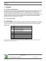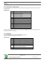
1
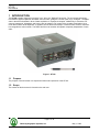
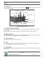
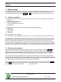
HT100
USER MANUAL
Version: 1.6
Odom Hydrographic Systems, Inc.
1450 Seaboard Avenue
Baton Rouge, Louisiana
USA
70810-6261
Telephone: (225) 769-3051
Fax: (225) 766-5122
[email protected]
http://www.odomhydrographic.com
Number of pages: 39
Date: May 1, 2003
HT100
User Manual
© ODOM HYDROGRAPHIC SYSTEMS, INC. 2003
All rights are reserved. Reproduction in whole or in part is prohibited without the prior written consent of the copyright owner.
The information presented in this document does not form part of any quotation or contract, is believed to be
accurate and reliable and may be subject to change without notice. The publisher will not accept any liability for
any consequence of its use. Publication thereof does not convey nor imply any license under patent- or other
industrial or intellectual property rights.
Page 2 of 39
Odom Hydrographic Systems, Inc.
May 1, 2003
HT100
User Manual
CONTENTS
1
Introduction.......................................................................................................................................................5
1.1
1.2
1.3
1.4
2
Product description..........................................................................................................................................7
2.1
2.2
2.3
2.4
2.5
2.6
2.7
2.8
2.9
2.10
2.11
2.12
2.13
2.14
2.15
3
Purpose ........................................................................................................................................................5
Scope ...........................................................................................................................................................5
Glossary .......................................................................................................................................................6
References ...................................................................................................................................................6
Specifications ...............................................................................................................................................7
Overview ......................................................................................................................................................8
Choice of operating frequencies ..................................................................................................................8
Signal connector ..........................................................................................................................................8
Power connector ..........................................................................................................................................8
Fuse .............................................................................................................................................................8
Power switch ................................................................................................................................................8
Power indicator.............................................................................................................................................9
TX indicator ..................................................................................................................................................9
GPS antenna ............................................................................................................................................9
GPS control input .....................................................................................................................................9
GPS output ...............................................................................................................................................9
Control ......................................................................................................................................................9
Data out ....................................................................................................................................................9
High/Low switch........................................................................................................................................9
Installation.......................................................................................................................................................10
3.1
Software installation ...................................................................................................................................10
3.2
Setting up the equipment ...........................................................................................................................10
3.3
Powering up the equipment .......................................................................................................................11
3.4
Transducer installation ...............................................................................................................................11
3.4.1
“THROUGH HULL” transducer installation .........................................................................................12
3.4.2
"SEA CHEST" transducer installation .................................................................................................13
3.4.3
"OVER-THE-SIDE" transducer installation .........................................................................................14
4
HT100 APPLICATION .....................................................................................................................................15
4.1
Introduction:................................................................................................................................................15
4.2
Starting the Application: .............................................................................................................................15
4.3
Basic functionality ......................................................................................................................................16
4.3.1
Real-time / Simulator mode ................................................................................................................16
4.3.2
Menu structure ....................................................................................................................................16
4.3.3
Chartview application structure...........................................................................................................17
4.3.4
Using the COM-log window ................................................................................................................18
4.3.4.1
Selecting the COM-ports .............................................................................................................19
4.3.4.2
Opening/Creating the log file .......................................................................................................19
4.3.4.3
Closing the logfile ........................................................................................................................20
4.3.4.4
Converting the logfile ...................................................................................................................20
4.3.5
Automated logging of parameter settings ...........................................................................................21
4.3.6
HT100 windows application operation ................................................................................................22
4.3.6.1
Setting up Communication ..........................................................................................................22
4.3.6.2
Enable/Disable Communication ..................................................................................................22
4.3.6.3
Standby mode..............................................................................................................................22
4.3.6.4
DSP-interface ..............................................................................................................................22
4.3.6.5
Simulator mode............................................................................................................................22
Page 3 of 39
Odom Hydrographic Systems, Inc.
May 1, 2003
HT100
User Manual
4.3.6.6
COM monitor & Status window....................................................................................................23
4.3.6.7
Range ..........................................................................................................................................23
4.3.6.8
Transmit Power............................................................................................................................23
4.3.6.9
Receive Gain ...............................................................................................................................23
4.3.6.10 TX pulse width.............................................................................................................................23
4.3.6.11 Blanking.......................................................................................................................................24
4.3.6.12 Units ............................................................................................................................................24
4.3.6.13 Frequency ...................................................................................................................................24
4.3.6.14 TVG curves .................................................................................................................................24
4.3.6.15 TVG Gain Reference...................................................................................................................24
4.3.6.16 Digi-Algorithm..............................................................................................................................24
4.3.6.17 Ping rate ......................................................................................................................................24
4.3.6.18 Sim. Gain (Simulator Gain) .........................................................................................................24
4.3.6.19 Graph type...................................................................................................................................24
4.3.6.20 Language ....................................................................................................................................24
4.3.6.21 Outputstring.................................................................................................................................25
4.3.6.22 Bar depth & Bar width .................................................................................................................25
4.3.6.23 Sound velocity .............................................................................................................................25
4.3.6.24 Draft.............................................................................................................................................25
4.3.6.25 Index............................................................................................................................................26
4.3.6.26 End-of-Scale & Scale Width........................................................................................................26
4.3.7
Changing parameter values................................................................................................................27
5
Overview parameter settings ........................................................................................................................28
6
Operational procedures .................................................................................................................................29
6.1
How to calibrate the HT100........................................................................................................................29
6.2
How to perform a bar check .......................................................................................................................30
6.3
Using the optional built-in Starlink Invicta DGPS .......................................................................................31
6.3.1
Introduction .........................................................................................................................................31
7
Troubleshooting .............................................................................................................................................32
7.1
7.2
7.3
7.4
7.5
7.6
8
Problems installing the HT100 Windows application .................................................................................32
How to copy the HT100 windows installation files to disk..........................................................................32
The HT100 does not seem to be working ..................................................................................................33
The HT100 power LED is off......................................................................................................................33
The HT100 power LED is flickering ...........................................................................................................33
What are the COM-port settings ................................................................................................................33
Appendix .........................................................................................................................................................34
8.1
Computer communications ........................................................................................................................34
8.2
Serial output strings ...................................................................................................................................34
8.2.1
Echotrac SBT ......................................................................................................................................34
8.2.2
Echotrac SBT + signal strength ..........................................................................................................35
8.2.3
NMEA DBS .........................................................................................................................................35
9
Serial Cable Connections for Hydrotrac with Built in GPS ........................................................................37
Appendix A. CABLE CONNECTIONS: ..................................................................................................................38
Page 4 of 39
Odom Hydrographic Systems, Inc.
May 1, 2003
HT100
User Manual
1 INTRODUCTION
The HT100 portable “digital echo sounder” is an "all-in-one" Digitizer/Transceiver. The unit shares technology
from both the popular Hydrotrac and MKIII echo sounders, giving the user the option to go “all digital”. The paper
chart is therefore eliminated in favor of data acquisition on a personal computer. Additionally, it makes the unit
compact, waterproof, lightweight, and hence, easy to transport. Full control of the sounder is maintained via a
menu that is similar to the Hydrotrac. In addition, the unit shares the ability to include a DGPS receiver inside the
box alongside the echo sounder. The DGPS and the echo sounder will operate completely independent of each
other.
Figure 1: HT100
1.1
Purpose
The purpose of this document is to explain the features and operation of the HT100.
1.2
Scope
The content of this document is focused on the end-user.
Page 5 of 39
Odom Hydrographic Systems, Inc.
May 1, 2003
HT100
User Manual
1.3
Glossary
DBS
DBT
DGPS
DSP
HT100
NMEA
OHSI
SBT
TNC
TVG
VDC
1.4
Depth Below Surface
Dual Bottom Tracking
Differential Global Positioning System
Digital Signal Processor
Hydrotrac 100
National Marine Electronics Association
Odom Hydrographic Systems Incorporated
Single Bottom Tracking
Threaded Nut Connector
Time Varied Gain
Volts Direct Current
References
N/A
Page 6 of 39
Odom Hydrographic Systems, Inc.
May 1, 2003
HT100
User Manual
2 PRODUCT DESCRIPTION
2.1
Specifications
Frequency (The HT100 is frequency agile in two bands; to be specified at time of order.)
High: 100 kHz – 750 kHz,
Low:
12 kHz – 50 kHz (Manual tuning in 1 kHz steps for both High and Low)
Resolution
0.01 meter, 0.1 feet
Accuracy (Corrected for sound velocity)
200 kHz - 0.01 meter ± 0.1% depth,
33 kHz - 0.10 meter ±0.1% depth
Output Power
Up to a maximum of 300 Watts RMS in both High and Low Bands (range dependent)
Ping Rate
Up to 20 Hz in shallow (10 m.) range
Depth Range
From 20 centimeters (0.8 ft.) to 600 meters (2000 ft.)
Input Power Requirement
9-32 VDC, less than 30 Watts
Weight
5 kg. (11 lb.)
Dimensions
Width 28 cm. (11”) x Length 23 cm. (9”) x Height 11.5 cm. (4.5”)
Mounting
Desktop or Bulkhead (hardware supplied)
Ports / Interface
* RS232 (input for control and annotation, output for depth and sounder condition data)
(Supported output string format: Odom Echotrac SBT + signal strength, NMEA)
* RS232 (depth plus sounder condition data)
* RS232 (GPS control input for optional internal GPS)
* RS232 (GPS output for optional internal GPS)
Features
Windows graphical user interface
Multiple TVG (Time Varied Gain) Curves 10, 20, 30 and 40 Log)
Auto Gain Control
DSP Digitizer with manual filter control
Manual or Auto Scaling (Phasing)
Calibration menu with controls for transducer draft, index, sound velocity and bar depth controls.
Internal DGPS (Optional)
Waterproof
Help menus
Flash memory upgradeable
Comlogger and logging features
Page 7 of 39
Odom Hydrographic Systems, Inc.
May 1, 2003
HT100
User Manual
2.2
Overview
All the I/O, controls and indicators of the HT100 are shown below, in Figure 2. Each item will be explained in more
detail in the following chapters.
GPS antenna
Control
Tx indicator
GPS
control input
Power indicator
Power switch
Fuse
Power connector
Signal connector
Data out
GPS output
High/Low switch
Figure 2: Overview of HT100
2.3
Choice of operating frequencies
The HT100 can be configured to use either a High or a Low frequency board, respectively 100 kHz – 750 kHz or
12 kHz – 50 kHz.
Standard transducers are generally available from stock that support the frequency ranges listed above.
2.4
Signal connector
The signal from the transducer is passed to the HT100 via a special cable and twist-lock connector. The twist-lock
connector is attached to the HT100 where a connector is labeled “Transducer”.
2.5
Power connector
The HT100 requires a DC voltage from 9 to 32 Volts.
2.6
Fuse
The fuse for the HT100 is located behind the waterproof twist-lock cap. If the fuse needs to be replaced, it must
be a standard glass tube fuse and have a value of 5-Amp / 250 Volts.
2.7
Power switch
The power switch in the ON position will power-up the internal circuitry. In the OFF position it will power-down the
internal circuitry.
Page 8 of 39
Odom Hydrographic Systems, Inc.
May 1, 2003
HT100
User Manual
2.8
Power indicator
When the HT100 is turned on, a green LED will be on to indicate that the internal systems have powered up
successfully.
2.9
TX indicator
The TX indicator on the HT100 indicates whether the Transducer is firing or not. The frequency at which the TX
indicator flickers also indicates whether the Transducer is firing at a slow or fast pace.
2.10 GPS antenna
The GPS antenna for the optional internal GPS can be attached to the TNC connector labeled “GPS antenna”.
2.11 GPS control input
The DB9 (RS232) connector labeled “GPS INPUT” is used to configure the optional internal GPS or enter RTCM
corrections to the internal GPS. On the physical GPS unit this would be labeled as port A or B. The internal GPS
system is an optional feature and does not come standard in the HT100.
2.12 GPS output
The DB9 (RS232) connector labeled “GPS OUTPUT” is used to output the GPS data from the optional internal
GPS system. On the physical GPS unit this would be labeled as port A or B. The internal GPS system is an
optional feature and does not come standard in the HT100.
2.13 Control
The DB9 (RS232) connector labeled “CONTROL” is used to connect to your personal computer that will be
running the HT100 windows application software. This software will provide the means to control the HT100. The
HT100 windows application software also uses this DB9 I/O port to receive the depth values acquired by the
transceiver circuitry.
2.14 Data out
The DB9 (RS232) connector labeled “DATA OUT” can be used to pass all the acquired depth to a third party.
2.15 High/Low switch
Not used.
Page 9 of 39
Odom Hydrographic Systems, Inc.
May 1, 2003
HT100
User Manual
3 INSTALLATION
This section contains the information necessary to install the HT100 Software, power-up and connect the HT100.
The installation procedure consists of a number of steps. Each step corresponds to a specific chapter. It is
recommended that these steps (chapter 3.1, 3.2 and 3.3) for the installation procedure be followed in this order.
3.1
Software installation
The minimum requirements for a personal computer to install and run only the HT100 Application software are:
• Windows 98
• Pentium-I, running at 200 MHz
• 32 Mb of internal memory
• 11 Mb of free space on the harddrive
• One COM-port
The HT100 windows application is fully tested on the following Operating Systems:
• Windows 98
• Windows 2000
• Windows XP
• Windows NT
Note: Windows ME is not supported.
Note: A minimum of three COM-ports are needed to run: HT100, Data Acquisition Software and GPS together.
The software that is shipped with the unit can be installed on the personal computer by executing the program
called SETUP.EXE. This program will install the HT100 software in the Program Files directory. During the setup
process it is possible that Windows will ask if you wish to keep certain files on the computer that are older or
newer than the ones being installed. By default it is advised to keep the files that are currently on the computer to
avoid any conflicts or problems with other programs. If during the setup process, the setup program cannot find
the files on your computer that it needs to install the HT100, the missing file(s) will be copied onto the hard drive.
3.2
Setting up the equipment
The HT100 is a lightweight unit designed for portability. An interconnection diagram is shown in Figure 3. Care
should be taken to route cables using horizontal and vertical runs wherever possible. Avoid paths that run
adjacent to transmitter feeder cables or close to heat radiating elements such as steam pipes. For permanent
installations, cables should be clamped at regular intervals (3 feet or 1 meter) along their complete lengths.
The HT100 requires an input voltage between: +9 and +32 VDC (standard). The unit consumes less than 30
watts of power in normal operation. Power is frequently derived from one or two 12 V lead-acid Marine batteries.
Two Marine batteries (24V configuration), fully charged, and in good condition, can normally power a unit for a full
day without re-charging. Details of the power cable are given in the Appendix.
All cables are attached to the connectors located in the recessed area at the left rear of the unit (See Figure 2 in
chapter 2.2). Connections are made through multi-pin “MS” style connectors, between the HT100, its power
source, the transducer and all computer or
peripheral devices.
Page 10 of 39
Odom Hydrographic Systems, Inc.
May 1, 2003
HT100
User Manual
External GPS
GPS control input
HT100
Internal GPS
GPS Antenna
Power
DATA out
GPS output
CONTROL
Computer
Transducer
Figure 3: Interconnection block diagram
Before connecting any of the cables, make sure that the computer, the HT100 and other peripherals are turned
off. The list below is a sequence of steps for connecting the HT100 with the computer and GPS. If any problems
arise, see the Troubleshooting section.
1. Connect the RS232 cable between the computer and the DB9 connector labeled “CONTROL”.
2. Connect the cable from the Transducer to the connector on the HT100 labeled “Transducer”.
3. Connect the power cable for the HT100 to the connector labeled “POWER”.
If the optional internal GPS is used, then:
4. Configure the optional internal GPS, using special software, through the connector labeled “GPS INPUT”.
5. Connect the GPS antenna cable to the connector labeled “GPS antenna”.
6. Connect the RS232 cable between the connector labeled “GPS OUT” with a COM-port on the computer.
If an external peripheral or Data Acquisition Software is used, then:
7. Connect the RS232 cable between the connector labeled “DATA OUT” with the external peripheral, or
connect it to a COM-port on the computer to use it with Data Acquisition Software for the depth out.
Note, after configuring the HT100, the RS232 cable from the computer to the connector labeled “CONTROL”
may be removed. The COM port on the computer can then be used for something else.
3.3
Powering up the equipment
The following sequence must be followed when powering up the equipment:
1. Turn on the personal computer.
2. Turn on the HT100.
3. Start the HT100 Window Application program.
Note: The HT100 should always be turned on before running the HT100 Application program.
3.4
Transducer installation
Proper mounting of the transducer is a crucial part of the installation of any "survey" echo sounder. An improperly
mounted transducer will result in poor system operation and unacceptable data quality.
In the case of temporary installations, the transducer is often mounted over-the-side. In permanent installations
and "pay surveys," hull mounts are generally preferred and often required. In either case, the transducer should
be mounted as far below the waterline as possible. In cases where "over the side" mounts are exposed to wave
action, ensure that the transducer is mounted far enough below the surface so that it remains well submerged
during vessel roll motions.
Page 11 of 39
Odom Hydrographic Systems, Inc.
May 1, 2003
HT100
User Manual
A preferred mounting location is near the keel of the vessel, in an area where the planing attitude of the hull and
the pitch and roll angles of the vessel have the least effect at operating speed. The transducer should be
mounted far enough aft of the bow so that bubbles generated by the bow wave will not pass over the face of the
unit. Transducers should be located away from sources of turbulence and cavitation bubbles such as propellers,
bow thrusters and hull protrusions. Consideration should also be given to sources of mechanical noise generated
within the vessel (engines, propellers, pumps, generators, etc.). In some severe cases of mechanically coupled
noise, vibration-isolating mounts may be required to mechanically decouple the transducer from the hull.
Transducer mounting can be accomplished in many different ways. The following three chapters show common
configurations.
3.4.1
“THROUGH HULL” transducer installation
The top side of the transducer is accessible from inside the vessel while the transducer face is directly exposed to
the water. Care should be taken to protect the transducer from damage and turbulence by installing a fairing with
a sloping forward edge ahead of the unit. The fairing has the dual effect of both minimizing possible strike
damage and smoothing the flow of water over the face of the transducer.
Figure 4: Transducer mounted through the hull
Page 12 of 39
Odom Hydrographic Systems, Inc.
May 1, 2003
HT100
User Manual
3.4.2
"SEA CHEST" transducer installation
In a "sea chest" mount, a fluid-filled enclosure large enough to contain the entire transducer is attached to the
outer hull of the vessel. The outer hull is removed within the area of the chest and replaced with an acoustically
clear "window" which is mounted flush with the hull surrounding the chest. Depending on construction, the
material selected for the acoustic window, and the draft of the vessel, access can often be gained to the
transducer from inside the hull without putting the vessel in dry-dock. In most installations, a water-filled
standpipe is incorporated into the "sea chest" design in order to provide hydrostatic pressure equalization.
Transducer cables generally leave these assemblies through stuffing tubes, which maintain the watertight integrity
of the chest.
Page 13 of 39
Odom Hydrographic Systems, Inc.
May 1, 2003
HT100
User Manual
3.4.3
"OVER-THE-SIDE" transducer installation
A mount of this type is frequently constructed from a length of pipe. This fixture should be sized to position the
transducer well below the waterline and the pipe then fixed to a sturdy support on the vessel. Lines generally are
attached at the transducer pipe and tied off fore and aft in order to maintain a stable, horizontal transducer
attitude. Care should be taken to assure adequate protection for the transducer cable, particularly at the point
where the cable leaves the transducer body.
In all of the above installations, particular care should be taken to assure that the transducer radiating face
remains as parallel to the water surface as much as possible while the vessel is moving.
Page 14 of 39
Odom Hydrographic Systems, Inc.
May 1, 2003
HT100
User Manual
4 HT100 APPLICATION
4.1
Introduction:
This section contains the information necessary to operate the HT100 unit using the HT100 Windows Application
Software.
4.2
Starting the Application:
After the HT100 software has been installed the windows application can be found at the following location (See
also Figure 6 below):
Click on START at the task bar (the start menu will appear).
Go to the menu item named Programs (a submenu will automatically appear).
Go to the menu item named HT100 in that submenu (another submenu will appear).
Click on the menu item HT100 in that submenu.
The HT100 windows program will now start with a so-called Splash screen as shown in Figure 5.
When the progress bar on the Splash screen has reached the end, the Main screen will appear as shown in
Figure 7.
The HT100 Application software is now ready to be used.
Figure 5: HT100 Splash screen
Figure 6: HT100 location in Windows menu
Figure 7: HT100 main screen
Page 15 of 39
Odom Hydrographic Systems, Inc.
May 1, 2003
HT100
User Manual
4.3
4.3.1
Basic functionality
Real-time / Simulator mode
The HT100 Application supports two modes:
• Real Time Acquisition (reading the output of the HT100 unit)
• Simulator mode
During Real Time Acquisition the HT100 windows application processes the data coming in from the HT100 and
displays them on the screen.
When the application is in Simulator mode, the data will be generated at random within the program and
displayed. The data generated at random can be affected by controls such as Transmit Power, Receive Gain and
Ping rate. The effect of these controls will be explained in the following chapters.
4.3.2
Menu structure
The application provides a menu with the following three main categories: FILE, SETUP and HELP. Each
category can be accessed by either clicking on it with the left mouse-button or by pressing the key-combination
ALT+<underlined letter>.
File
Setup (ALT+S)
(ALT+F)
Exit
(CTRL+X)
Reset Parameters (CTRL+R)
Open Logfile
Help (ALT+H)
Contents
About
Close Logfile
Convert Logfile
Load Settings (CTRL+L)
Save Settings (CTRL+S)
Figure 8: Menu structure
The item EXIT under the FILE menu will close the HT100 application.
The item OPEN LOGFILE will open/create a logfile that stores depth data.
The item CLOSE LOGFILE will close the logfile that stores depth data.
The item CONVERT LOGFILE will convert the logfile into a comma-separated file that can be read into Excel.
The item LOAD SETTINGS loads HT100 settings from a previously saved file.
The item SAVE SETTINGS saves the current HT100 settings to a file.
The item RESET PARAMETERS under the SETUP menu will change all the current settings to the default
settings.
The item CONTENTS under the HELP menu will display a windows help file that explains the operation and
functionality of the HT100 and the HT100 windows application.
The item ABOUT under the HELP menu will display information about the HT100 and the HT100 windows
application.
Page 16 of 39
Odom Hydrographic Systems, Inc.
May 1, 2003
HT100
User Manual
4.3.3
Chartview application structure
The parameter settings for the sounder are grouped into two main groups: Main Control parameter settings and
the Secondary parameter settings. The Main Control parameter settings are located on the left hand side of the
screen, while Secondary parameter settings are categorized under tabs on the right hand side labeled Setup and
Chart / Calibration. See Figure 9.
Main Control parameters: Range, Transmit Power, Receive Gain, TX Pulse width.
1
2
3
Secondary parameters:
Setup parameters,
Chart/Calibration parameters,
Comlog window.
4
5
6
7
8
Figure 9: HT100 windows application Main Control and Secondary parameter settings
The application has a number of sections designed to inform the user of the current operating settings. These
sections are numbered from 1 to 8 in Figure 9 and are explained in the following section.
1. The TX Standby panel shows if the HT100 is currently in Standby mode or not.
2. The COM-port control panel shows whether the COM-port used by the HT100 windows application is
currently Open or Closed.
3. The Depth panel shows the most recently acquired depth-data from the sounder or the most recently
generated depth value from the simulator. When errors occur or the digitized depth is zero, the depth value
will be displayed in yellow to indicate an “alarm” condition.
4. The graphical representation of the depth.
5. The Status Window panel indicates whether there is any activity on the COM-port. The checkbox on this
panel will visualize or hide the COM monitor.
6. The COM monitor shows the incoming data on the COM port and can be used for diagnostic purposes. For
example: text similar to “ET 174 986”, indicates the units are in Feet, the depth is at 17.4 feet, the signal
strength or energy gain is 986. Another example: text similar to “et 234 876”, indicates the units are in Meters,
the depth is at 2.34 meters, the signal strength or energy gain is 876. The energy gain can be a value
between 0 and 1024, where 0 is no signal strength and 1024 is the maximum signal strength.
7. The Status panel indicates when a communication error has occurred between the HT100 echo sounder and
the HT100 windows application.
8. The General Message panel provides assistance for the user to indicate any change in parameter or control
settings. Some parameter changes are not immediately transmitted to the echo sounder because they are
related to other parameter settings in the same tab. Once the user has made all the changes, those changes
can be transmitted to the HT100 by clicking on the Apply button. The General Message panel will remind the
user if parameter settings have been changed but have not been sent to the HT100.
Page 17 of 39
Odom Hydrographic Systems, Inc.
May 1, 2003
HT100
User Manual
4.3.4
Using the COM-log window
The HT100 windows application provides a tab named “Comlog” (see Figure 9). This tab contains a comlog
window that displays the data collected on the selected COM-ports. Data can be collected from a maximum of
three COM-ports. The com-port that is used to control the HT100 is by default the first com-port, which is selected
on the “Setup”-tab. Two other COM-ports can be selected on the “Comlog”-tab. This tab provides two checkboxes
that allows the user to select two other COM-ports. For example, a second COM-port may collect GPS data. The
data collected and displayed in the Comlog window may also be saved to a logfile.
Figure 10 shows an example of data collected on a COM-port. On slower computers, it may be necessary to
remove the check from the Display checkbox. A spinner will indicate that the Com-logger is collecting data on the
COM-ports.
Spinner
Figure 10: Comlog window
Page 18 of 39
Odom Hydrographic Systems, Inc.
May 1, 2003
HT100
User Manual
4.3.4.1 Selecting the COM-ports
A COM-port can be selected by clicking on one of the Monitor Port checkboxes named “com” by default. When a
COM-port is selected the checkbox will display the number of the selected COM-port. As soon as the user clicks
on a checkbox, a message box will pop up and ask for a valid COM-port number (see Figure 11). When a valid
COM-port number has been entered, a second message box will appear containing the default settings for that
COM-port (see Figure 12). These settings may need to be changed because data may be provided at a different
speed. When the correct settings have been provided, the checkbox will contain a checkmark. When data is
received it will be displayed in the Comlog window. If the data needs to be saved to a logfile, then a logfile must
be opened/created. See 4.3.4.2.
Figure 11: Selecting a COM-port
Figure 12: Selecting the COM-port settings
4.3.4.2 Opening/Creating the log file
A log file can be opened to append data or created as a new log file. Under the menu item File, the item Open
Logfile can be found. A window will appear where the user can choose a directory and filename under which the
log file needs to be saved (see Figure 13). As soon as the log file is opened or created and data is received, it will
be automatically saved in the log file. When the log file is closed, no more data will be saved to the log file.
Figure 13: Opening/Creating the log file
Page 19 of 39
Odom Hydrographic Systems, Inc.
May 1, 2003
HT100
User Manual
4.3.4.3 Closing the logfile
Under the menu item File, the item Close Logfile can be found. The logfile that is currently open will be closed.
Closing the logfile will have no affect on the Comlog monitor receiving data from the selected COM-ports.
4.3.4.4 Converting the logfile
After a logfile has been created and closed it can be converted to a comma-separated file (.CSV). A CSV file can
be imported into Excel for data analysis. Under the menu item File, the item Convert Logfile can be found. When
selecting this menu option, a window will appear as shown in Figure 14. The logfile that needs to be converted
can be selected by clicking on the Browse button. Figure 15 shows the window that will appear to allow the user
to select the filename of the logfile for conversion. A similar window will appear when the user selects a filename
for the CSV file that will contain the converted data.
Figure 14: Converting a logfile
Figure 15: Selecting the Logfile for conversion
Page 20 of 39
Odom Hydrographic Systems, Inc.
May 1, 2003
HT100
User Manual
4.3.5
Automated logging of parameter settings
The HT100 windows application has a built-in automated logging feature that logs all the parameter changes
made during normal operation. The feature is activated as soon as the HT100 windows application has
communicated with the HT100. Every parameter setting that is sent to the HT100 is logged in the automated
logfile. The automated logfiles are named and dated as shown in Figure 15 and in the following examples:
Examples filenames of the automated logfiles.
20021112_HT100.log
( Automated log file created on November 12, 2002 )
20021122_HT100.log
( Automated log file created on November 22, 2002 )
20021125_HT100.log
( Automated log file created on November 25, 2002 )
The filenames for the automated logfiles are created on a day-to-day base. If it is necessary to have individual
logfiles on the same day, the user will have to rename the logfile before starting the next survey.
The content of an automated logfile looks like the example shown below:
*********************************************
Time: 14:49:10 INITIALIZATION of HT100
Shows the time when the HT100 was initialized.
*********************************************
*********************************************
Time: 14:49:10 Parameter Update
Shows the time when the parameters were changed/updated.
*********************************************
Acknowledge Received... updating parameters. The HT100 is ready to receive new parameter values.
Units
:1 (Feet)
Range
:100
Sound velocity
:4920
Draft
:0
Index
:0
Bar depth
:0
Bar gate width
:3
TX blanking
:0
TX pulse width
:20
Frequency
:200
Receive gain
:0
Transmit power
:3
TVG curves
:1 (20 Log)
Digi-Algorithm
:3
*********************************************
Time: 14:50:25 INITIALIZATION of HT100
Shows when the HT100 was re-initialized or turned on again.
*********************************************
*********************************************
Time: 14:50:25 Parameter Update
*********************************************
Acknowledge Received... updating parameters.
Units
:1 (Feet)
Range
:100
Sound velocity
:4920
Draft
:0
Index
:0
Bar depth
:0
Bar gate width
:3
TX blanking
:0
TX pulse width
:20
Frequency
:200
Receive gain
:0
Transmit power
:3
TVG curves
:1 (20 Log)
Digi-Algorithm
:3
Page 21 of 39
Odom Hydrographic Systems, Inc.
May 1, 2003
HT100
User Manual
4.3.6
HT100 windows application operation
The HT100 should always be powered-up before starting the HT100 windows application. The application is
ready to be used when the main screen is displayed. See Figure 9. Any parameter changes made in the
application will be stored in the Windows Registry so that the next time the application is started the previous
settings will be loaded. The first time the application is installed on the computer and started; the default
parameter settings will be applied.
4.3.6.1 Setting up Communication
Before enabling the communication between the HT100 and the HT100 windows application, the correct COMport must be selected. The COM-port selection can be found on the Setup tab on the right side of the HT100
windows application. The COM-port settings used by default are: 9600 baud, 8 data bits, no parity, 1 stop bit.
4.3.6.2 Enable/Disable Communication
After setting up the communication port in section 4.3.6.1, the HT100 and the HT100 windows application are
ready to be operated. Upon start-up of the HT100 windows application the communication is always disabled. To
enable the communication between the HT100 and the HT100 windows application, click on the button next to the
red LED. See number 2 in Figure 9. The red LED will now be green to indicate that the COM-port has been
opened successfully. To disable the communication, click on the button next to the green LED. The green LED
will now be red to indicate that the COM-port has been closed.
By default the communication is always bi-directional, which is indicated by the DSP-interface checkbox on the
Setup tab. Also, the simulator mode is turned off by default. The simulator mode will be automatically disabled
when communication is enabled. See also the related sections about Standby, DSP-interface and Simulator.
4.3.6.3 Standby mode
The standby mode for the HT100 can only be enabled or disabled when the communication between the HT100
and the HT100 windows application is enabled. See section 4.3.6.2.
See number 1 in Figure 9. Enabling the standby mode will put the HT100 into standby and no more data will be
transmitted through the COM-port. Even though the HT100 is in standby mode, the HT100 will be able to receive
and process any parameter changes. The standby mode cannot be changed when the Simulator is running.
See also the related sections about Enable/Disable communication, DSP-interface and Simulator.
4.3.6.4 DSP-interface
The DSP-interface checkbox is used to enable bi-directional communication between the HT100 and the HT100
windows application. When the DSP-interface checkbox does not contain a checkmark, any parameter changes
will not be sent to the HT100. When the DSP-interface checkbox does contain a checkmark, any parameter
changes will be sent to the HT100.
The basic functionality of the DSP-interface is to put the HT100 windows application in the so-called Listen-mode
and will prevent any parameter changes made by accident, to be sent to the HT100.
See also the related sections about Enable/Disable communication, Standby and Simulator.
4.3.6.5 Simulator mode
The Simulator feature of the HT100 windows application allows the user to exercise or demonstrate the features
of the sounder without the restraint of having an HT100. The depth of the simulated return is varied by changing
one or more of the following: range, scale width, end-of-scale, transmit power or receive gain.
The Simulator mode can be activated on the Chart/Calibrate tab. When the Simulator checkbox contains a
checkmark, the simulator is enabled. If the communication between the HT100 and the HT100 windows
application is enabled, then communication will be closed when the simulator is enabled. If the simulator is
running when the Communication is enabled, the Simulator mode will be disabled.
See also the related sections about Enable/Disable communication, Standby and DSP-interface.
Page 22 of 39
Odom Hydrographic Systems, Inc.
May 1, 2003
HT100
User Manual
4.3.6.6 COM monitor & Status window
The COM-monitor can be made visible by putting a checkmark in the COM-monitor checkbox. See number 5 in
Figure 9. When the communication between the HT100 and the HT100 Windows application is enabled, all
incoming data will then be displayed in the COM-monitor window. The COM-monitor window is visible by default,
and it can be used to verify that the incoming data is synchronized and correct.
The status window indicates whether data is being received on the COM-port or whether the HT100 Windows
application is waiting for data to be received. If the communication between the HT100 and the HT100 Windows
application is disabled, the status window will display the message: “No data received”. If the HT100 is running
and outputting data, the message “Data received” is displayed. If the communication is enabled and the HT100
Windows application is not receiving any data from the HT100, the message: “Waiting for data” is displayed.
4.3.6.7 Range
The Range parameter limits the maximum range of the digitizer. For example, when a range value of 100 meters
is selected, the digitizer will never look deeper than 100 meters for a valid bottom return signal. This speeds up
the digitizer since it no longer has to expand the tracking gate to include depths greater than 100 meters. The
feature is often used in conditions where the time needed to re-acquire the bottom (after the signal is lost) must
be minimized. However, care should be taken not to set the range at a value that is too shallow, since it will also
prevent tracking valid returns deeper than the selected range value.
4.3.6.8 Transmit Power
Real-time acquisition mode
The transmit power controls the amplitude or strength of the transmitted acoustic pulse or so-called “Ping”. As is
the case with all echo sounders, bottom conditions and water depth are the primary determining factors in the
operator’s selection of transmit power level. Deep water and or poor bottom reflectivity (mud or organic material)
may dictate using a higher power level. A low power level will generally work better in shallow water and sandy or
rocky bottoms.
Simulator mode
During simulator mode the transmit power reduces the receive gain setting by a small portion, and basically acts
as a fine-tuner.
4.3.6.9 Receive Gain
Real-time acquisition mode
The receive gain magnifies the return signal to allow the digitizer to detect and process the return signal. The
receive gain parameter can also be set to Auto by putting a checkmark in the checkbox. The HT100 will then
automatically adjust the receive gain based on the return signal. When Auto is unchecked, the previous receive
gain setting will be used again.
Simulator mode
During simulator mode the receive gain affects the jump-size. A high receive gain value will result in a rough
graph; while a low receive gain value will result in a smoother graph. A rough looking graph can be smoothed-out
by increasing the transmit power.
4.3.6.10 TX pulse width
The TX Pulse Width value in combination with the Frequency determines signal range and signal penetration of
the bottom. When the user has changed the TX Pulse Width value in the HT100 windows application, it is
automatically sent to the HT100 unit.
Page 23 of 39
Odom Hydrographic Systems, Inc.
May 1, 2003
HT100
User Manual
4.3.6.11 Blanking
A blanking feature is used to “mask” the transmit pulse, transducer ringing, or other unwanted acoustic returns in
the upper water column (such as boat wakes) from the digitizer. It is applied when these acoustic events could be
mistaken for returns from the seabed or when the operator needs to force the sounder to “look” below an
interference layer. The value for Blanking is entered as a distance from the water surface.
4.3.6.12 Units
Two choices are possible under the Units parameter, Feet or Meters. Changing the Units parameter requires that
the Digitizer processor recalculates the values for all parameters and the graph scale. This process can take a
few seconds and therefore the HT100 is put into standby mode. When all the parameters have been processed,
the HT100 will acknowledge and return to normal operation mode.
4.3.6.13 Frequency
The Frequency value determines the harmonic frequency of the sound wave produced by the transducer. When
the user has changed the Frequency value in the HT100 windows application, the Apply button needs to be
pressed to send the values to the HT100 unit.
4.3.6.14 TVG curves
The TVG Curve value determines which Logarithmic scale the HT100 uses. In shallow water the 10 log should be
used. When the user has changed the TVG Curve value in the HT100 windows application, the Apply button
needs to be pressed to send the values to the HT100 unit.
4.3.6.15 TVG Gain Reference
This feature allows the user to select a delay in milli-seconds for the TVG curve. If the transducer is locked on the
wrong return signal, the gain reference can delay the TVG curve and allow the transducer to lock onto the correct
return signal.
4.3.6.16 Digi-Algorithm
The user is able to select between 9 different digitizer algorithms. Selecting 1 will result in default operation and
no averaging will be performed. Any value above 1 will produce a number that is the average of over the previous
number of samples selected by the digi-algorithm setting. For example, increasing the digi-algorithm setting to a
higher number will produce a better depth value because reflections of air-bubbles are eliminated through
averaging. The default setting is 3.
4.3.6.17 Ping rate
The ping rate is only available and visible in simulator mode and refers to the pulse repetition rate of the simulated
echo sounder. The minimum is two soundings per second and the maximum is twenty soundings per second.
4.3.6.18 Sim. Gain (Simulator Gain)
The simulator gain is only available and visible in simulator mode and allows the user to simulate the value of the
energy gain. The minimum is one and the maximum is ten. The default setting is 5.
4.3.6.19 Graph type
The graph displayed is composed of joint lines. A line will be drawn between every two depth values. The
thickness of the line depends on the energy gain, which can be adjusted by changing the receiver gain value.
4.3.6.20 Language
At this moment only English is available. Future versions will also support German and Spanish.
Page 24 of 39
Odom Hydrographic Systems, Inc.
May 1, 2003
HT100
User Manual
4.3.6.21 Outputstring
The HT100 supports three output strings: Echotrac SBT, Echotrac SBT + signal strength and NMEA DBS. See
chapter 8.2 for more information on these output string formats.
4.3.6.22 Bar depth & Bar width
The bar depth value is the difference in height between the water surface and the bar. The bar width is the height
range above and below the physical bar. When the bar width and/or bar depth have changed, the Apply button
must be pressed in order to send the new values to the HT100.
To enable the bar and start the calibration, the bar depth value must be greater than zero. The bar will become
visible when the bar depth falls within the graph range. When the bar depth is zero, the calibration mode is turned
off. If the bar depth is greater than zero and another tab is selected, a dialog window will inform you that the
calibration mode will be turned off and the bar depth is reset to zero.
The bar depth and bar width will each be displayed in a color other than the color already used for displaying the
graphical depth.
Transducer
Bar depth
Bar
Bar gate width
4.3.6.23 Sound velocity
The Sound Velocity value is a calculated average distance per second for a sound wave traveling through water.
The velocity at which sound travels through water depends on the depth at which the sound wave travels, salinity
and temperature of the water. The Sound Velocity value is used by the HT100 to determine the measured depth.
When the user has changed the Sound Velocity value in the HT100 windows application, the Apply button needs
to be pressed to send the values to the HT100 unit.
The sound velocity is incorporated into the depth calculation formula in order to facilitate calibration procedures
such as bar-checks.
Having the ability to change the speed of sound increases the accuracy of the system by allowing the sounder to
adapt to changing local conditions that affect the propagation speed of sound in the water. Whether derived as a
result of the “Bar Check” method of calibration, or taken directly from a velocimeter, the sound velocity is critical to
measurement accuracy.
4.3.6.24 Draft
The draft parameter value is the difference in height between the water surface and the transducer. It is a
correction value that is added to the raw digitized depth in order to adjust for the difference between the apparent
depth of the transducer and the water’s surface.
Page 25 of 39
Odom Hydrographic Systems, Inc.
May 1, 2003
HT100
User Manual
Draft
Transducer
Depth
4.3.6.25 Index
The index parameter is the correction value that is subtracted from the raw digitized depth in order to compensate
any calibration offset that may exist.
4.3.6.26 End-of-Scale & Scale Width
The Scale Width value is the difference in height that determines the limits between which the depth values are
plotted. The End-Of-Scale value determines one of the Scale Width limits. By adjusting the End-Of-Scale value,
the plotted depth values shift proportionally to the center of the scale width. The minimum value for the End-OfScale parameter is the same as the minimum value for the Scale Width parameter, because the End-Of-Scale
value cannot be smaller than the Scale Width value. When the user has changed the End-Of-Scale or Scale
Width value in the HT100 windows application, the Apply button needs to be pressed to send the values to the
HT100 unit.
When the Auto-scale checkbox contains a checkmark, the HT100 windows application will track the digitized
depth values and adjust the graph scale to follow the digitized depth. If the digitized depth exceeds the end-ofscale value, the End-Of-Scale value is incremented. If the digitized depth is too low to be displayed with the
current graph settings, the End-Of-Scale value is decremented. When Auto-scaling is turned on, the scale width is
not affected.
Draft
Transducer
Depth
Scale width
End of Scale
Page 26 of 39
Odom Hydrographic Systems, Inc.
May 1, 2003
HT100
User Manual
4.3.7
Changing parameter values
For certain parameters in the HT100 windows application it is possible to type a new value rather than using the
provided buttons for changing the current parameter value.
The following list of parameters allow manual editing of the parameter value:
• Blanking
• Frequency
• Bar depth
• Bar width
• Sound velocity
• Draft
• Index
• End of scale
• Scale width
To change the parameter value, use the right mouse button and click on the parameter’s textbox.
A message box will appear in which the parameter value can be edited. An incorrect value will not be accepted. If
the cancel button is pressed, the value in the message box is not accepted and the original parameter value is
kept. Pressing the OK button will accept the new parameter value if it is within the valid range of values.
Page 27 of 39
Odom Hydrographic Systems, Inc.
May 1, 2003
HT100
User Manual
5 OVERVIEW PARAMETER SETTINGS
The table below shows all the parameters with their ranges and limitations. For example: Bar depth has a
minimum value of 0 feet and a maximum value of 1000 feet. The value increments or decrements by 1. The
default setting is 0. The APPLY button needs to be pressed to update the new value to the HT100. The bar depth
is automatically converted when the units change. When the Apply button is pressed, all parameters are updated,
converted and sent to the HT100.
Some parameters are automatically sent to the HT100, such as the Range, Transmit Power, Receive Gain and
TX Pulse Width.
Parameter
Bar depth
Bar width
Blanking
Digi-Algorithm
Draft
End-of-Scale
Frequency
Index
Language
Output string
Ping rate
Range
Receive gain
Scale width
Sound velocity
Transmit power
TVG curves
TVG Gain
reference
TX pulse width
Units
Range
Min.
Max.
0
1000
0
300
1
12
1
5
0
1000
0
300
0
9
0
5000
0
1500
15
1200
5
400
15
350
0
5000
0
1500
English
German
Spanish
NMEA DBS
Echotrac SBT
Echotrac SBT + signalstrength
1
20
60
2000
20
600
0
255
15,30,60,120,240,300,600,1200
, 2000
5,10,20,40,80,100,200,400, 600
4500
5600
1370
1700
0
8
10 log
20 log
30 log
40 log
-
Units
Increment
Default
Updated
Conversion
Feet
Meters
Feet
Meters
Feet/10
Cm.
N/a
Feet/10
Cm.
Feet
Meters
N/a
Feet/10
Cm.
N/a
N/a
N/a
1
1
1
1
1
1
1
1
1
5
1
1
1
1
N/a
N/a
N/a
0
0
0
0
0
0
0
0
0
300
100
200
0
0
English
-
Apply
Apply
Apply
Apply
Apply
Apply
Apply
Apply
Apply
Apply
Apply
Apply
Apply
Apply
N/a
-
Yes
Yes
Yes
Yes
Yes
Yes
N/a
Yes
Yes
Yes
Yes
N/a
Yes
Yes
N/a
-
N/a
N/a
Echotrac
SBT
Apply
No
N/a
Feet
Meters
N/a
1
10
5
1
20
300
100
0
Directly
Directly
Directly
Directly
N/a
Yes
Yes
N/a
Feet
N/a
30
Apply
No
Meter
Feet
Meters
N/a
N/a
-
N/a
1
1
1
N/a
-
10
4920
1500
0
20 log
-
Apply
Apply
Apply
Directly
Apply
-
No
Yes
Yes
N/a
N/a
-
25, 50, 100, 200, 400
N/a
N/a
50
Apply
N/a
1
N/a
N/a
N/a
Feet
Meters
1
N/a
N/a
10
Feet
-
Directly
Directly
Directly
N/a
N/a
N/a
20
N/a
N/a
Page 28 of 39
Odom Hydrographic Systems, Inc.
May 1, 2003
HT100
User Manual
6 OPERATIONAL PROCEDURES
6.1
How to calibrate the HT100
The principle of echo sounding is based on measuring the time of arrival of an acoustic return (echo) referenced
to the time of transmission. The time required for sound to travel from a source (the transducer) to a destination
point (the seafloor or bottom) and back can be measured and multiplied by the velocity of sound in water. This
provides us with the distance that the pulse has traveled in the water column. Because the transmitted pulse
traveled from the transducer to the bottom and back again, the distance must be halved to obtain the true water
depth. Furthermore, other factors need to be included into the formula. If the transducer is submersed under
water, the distance from the water surface to the transducer, in other words the draft value, must also be
accounted for. If the calculated water depth does not exactly match the physically measured water depth, the
index value is used as a correction offset. The general depth formula is shown below.
D = v x t +k +dr
2
Where:
d
V
T
K
Dr
- Actual depth from water surface to the bottom.
- Average velocity of sound in the water column.
- Elapsed time measured from the transducer to the bottom and back to the transducer.
- Index constant.
- Distance from the referenced water surface to the transducer (draft).
Since the accuracy of measuring the depth depends on the value used for the velocity of sound in water (along
with the other factors shown above), it is important that a realistic value for sound velocity is used. In water,
velocity is a function of temperature, salinity and pressure. Therefore, the sound velocity in one area may vary
from the sound velocity measured in another area. This means that whichever type of echo sounder is used, it
must be calibrated in order to provide the most accurate depth data at a given location.
The most common calibration technique is the “Bar-Check” method. This method, when employed properly, has
the advantage of determining the sound velocity, draft, and index value. When this method of calibration is used,
acoustic sound waves are bounced off a suspended target that is lowered to a known depth between the
transducer and the bottom. In this situation it is desirable that the digitizer will see only the Bar (the target) and is
unable to lock on to acoustic returns from the bottom. Because the HT100 employs a dynamic tracking gate or
window through which the digitizer looks for returns or echoes from the bottom, manual control for the position
and width of the gate is necessary. This will force the digitizer to only detect returns from the Bar. See section 6.2
on how to perform a bar-check.
Page 29 of 39
Odom Hydrographic Systems, Inc.
May 1, 2003
HT100
User Manual
6.2
How to perform a bar check
This section describes an example of how to perform a bar-check.
1. Setup the equipment and start the HT100 Windows application program.
2. Set the Range at 60 feet. Select the bar-depth (start with a shallow depth, typically 5 feet), bar-width (typically
1 foot), Sound velocity, Draft (measured), Index (start with 0), End-of-scale and Scale width. Press the Apply
button to confirm the new settings. The HT100 Windows application is now in calibration mode because the
bar-depth is greater than “0”. The graph will display the tracking gate at the selected width, centered about the
selected bar-depth.
3. Lower the bar into the water column and place it at 5 feet below the water’s surface. The Digitizer in the
HT100 will expect to see a target at that 5.00-foot depth while rejecting all other returns (including those from
the bottom). Confirm that the return is displayed between the bar-width limits and that the digitizer is locked to
the bar.
4. Adjust the index to the correct depth and match what the digital graph is showing and press Apply to confirm
the new settings.
5. Change the bar depth in the HT100 Windows application and press Apply.
6. Adjust the sound velocity up or down until the digitized depth matches the measured bar depth.
7. Repeat steps 3, 4, 5 and 6 to verify the calibration procedure until your reading matches the depth of the bar.
Remember that the HT100 Windows application will show changed settings in red until the Apply button is
pressed.
IMPORTANT:
Adjust the draft only when the bar is at the shallowest depth, because this is where the sound velocity has little
affect on the calibration.
Adjust the sound velocity only when the bar is lowered to greater depths, because this is where the sound
velocity becomes pre-dominant.
Transducer
Draft + Index
Bar depth
Bar
Bar gate width
The figure above shows that the bar is placed under the transducer and kept at a certain measured depth using
cables.
Page 30 of 39
Odom Hydrographic Systems, Inc.
May 1, 2003
HT100
User Manual
6.3
6.3.1
Using the optional built-in Starlink Invicta DGPS
Introduction
The optional internal DGPS receiver for the HT 100 is intended to provide the user with a compact and rugged
hydrographic survey tool. With the addition of a data acquisition computer and appropriate software, a complete
survey system can be achieved with only two “boxes.” This can be a great advantage in remote or otherwise
inaccessible areas where portability, quick mobilization, and ease of operation are important.
As shipped from the factory, the Starlink Invicta 210 DGPS board is configured to use the integral MSK beacon
receiver for differential corrections, and to output the GLL string on the COM-port labeled “GPS OUT”. The
standard configuration can easily be changed using the program GPSMon.exe. The setup program is provided
on disk with the unit, and can also be downloaded from Starlink’s web site at www.starlinkdgps.com. The
program runs on any PC running the Windows operating system. Set up information is exchanged through one of
the serial ports on the PC and COM-port labeled “GPS INPUT” of the HT100. Changes in the configuration do not
require the operator to physically access the board.
Page 31 of 39
Odom Hydrographic Systems, Inc.
May 1, 2003
HT100
User Manual
7 TROUBLESHOOTING
7.1
Problems installing the HT100 Windows application
If the installation process does not following the steps described in chapter 3, it is possible to perform a manual
installation. If problems persist, contact Odom Hydrographic Systems, Incorporated.
7. If you are having problems installing the HT100 windows application and the operating system is
Windows ME (Millennium), try installing the software on a different Operating System such as: Window
s98, 2000, XP or NT. Windows ME is not supported.
2. The installation process only executes the first part of the process, namely copying files and then displays a
message to restart windows. Make sure you are not using Windows ME (millennium). Try installing the software
manually as described below (You may need assistance from your systems administrator):
2a.
Go to the folder C:\Program Files
2b.
In the Program Files folder, create a folder named HT100.
2c.
Copy the HT100.EXE file from the Support folder on the CD-ROM to the HT100 folder previously created.
2d.
Copy all the files with the extensions: .OCX, .DLL to your Windows System folder.
Example: C:\WINNT\SYSTEM or C:\WINDOWS\SYSTEM
2e.
Copy the file with the extension .TTF to the Windows Fonts folder.
Example: C:\WINNT\FONTS
or C:\WINDOWS\FONTS
Additional steps may be omitted and do no affect the programs operation.
2f.
You can now create a shortcut to the HT100.EXE program and place it on your desktop.
2g.
You can add the HT100 program to your windows menu for easy access.
7.2
How to copy the HT100 windows installation files to disk
It may be necessary to copy the HT100 installation files to 3.5“ floppy disks if the target computer does not have a
CD-ROM drive. In that case the table below lists all the necessary HT100 installation files and indicates to which
floppy disk they should be copied.
File on CD-ROM
SETUP.EXE
SETUP.LST
HT1001.CAB
HT1002.CAB
HT1003.CAB
Target 3.5” Floppy Disk
Disk 1
Disk 1
Disk 1
Disk 2
Disk 3
It is advised to create the following directory on the computer’s harddrive: C:\Installation\HT100
Copy the contents of each disk to the previously created HT100 folder in the Installation directory on the
harddrive. Then execute the setup.exe program from the HT100 folder. Follow the steps for the installation as
described in chapter 3.
If something accidentally happened to the disks, the original installation files will still be on the computer’s
harddrive. Also the installation process will be completed faster from the harddrive than when the disks are used
to install the HT100 windows application software.
Page 32 of 39
Odom Hydrographic Systems, Inc.
May 1, 2003
HT100
User Manual
7.3
The HT100 does not seem to be working
If the HT100 does not seem to be working right, follow the steps below to determine the cause.
7.3a
7.3b
7.3c
7.3d
7.3e
7.3f
7.3g.
7.4
Check if the power LED is on and does not flicker. If it does flicker, see section 7.5.
Check if all the cables are properly connected and intact. If cables are not properly secured, electrical
signals may not be transmitted or received.
Make sure you are using the correct COM-port. Select the correct COM-port in the HT100 windows
application. The HT100 windows application will display an error message if the port cannot be used or if
it is already open/used by another program. Programs or devices that use COM-ports are: Modem,
Mouse, Scanners, Printers.
Try toggling the COM-port off and on with the HT100 windows application software.
Make sure the HT100 is not in Standby mode.
A blinking TX LED means that the digitizer is firing, but the data may not be sent out on the COM-port of
the HT 100. The HT100 could be in Standby mode.
Try powering down the HT100 and powering it back up again. If the HT100 is turned on before the
computer, it may interfere with initializing and setting up communication channels.
The HT100 power LED is off
Try powering the HT 100 down and back up again.
If this does not resolve the problem, contact Odom Hydrographic Systems, Inc. for assistance.
7.5
The HT100 power LED is flickering
Reduce the Transmit power. It may be set too high with respect to the water depth.
7.6
What are the COM-port settings
The HT100 windows application uses the following default settings for the COM-port:
9600 baud, 8 data bits, no parity, 1 stop bit.
The COM-port used to interface with the HT100 can be selected on the Setup tab in the HT100 windows
application. See also section 4.3.6.1.
Page 33 of 39
Odom Hydrographic Systems, Inc.
May 1, 2003
HT100
User Manual
8 APPENDIX
8.1
Computer communications
Due largely to the pervasive presence of PC based data acquisition systems aboard survey vessels, the need has
arisen for echo sounders to communicate quickly and easily in a digital format. Two of the most common
communications interface formats are RS-232C and RS-422. The COM-port labeled “CONTROL” on the HT100
is capable of sending and receiving data in RS232 only. In its standard configuration, the unit sends ASCII
characters at 9600 baud, (8 data bits, 1 start bit, 1 stop bit, no parity) to peripherals or data logging systems at the
completion of each sounding cycle. COM-port “CONTROL” is a bi-directional serial port with the capability of
accepting input data as well as outputting serial depth information. A description of the protocol required for
changing the default output format follows in this section.
8.2
8.2.1
Serial output strings
Echotrac SBT
The HT100 I/O is compatible with the ECHOTRAC I/O, which is the standard serial output string first introduced in
the Echotrac DF3200 MKI in 1985. Due to the wide acceptance of this string and the availability of the format in a
number of data acquisition systems, the string has been maintained in order to assure continued compatibility.
OUTPUT format
Char. #
1
2
3
4
5
6
7
8
9
10
11
Description
Normally a Space, an “F” Indicates Fix Mark
“E” units are in tenths of feet
“e” units are in centimeters
“T” units are in tenths of feet
“t” units are in centimeters
Normally a Space, an “E” indicates Error
Always a space
Depth Data (MSD)
Depth Data
Depth Data
Depth Data
Depth Data (LSD)
Carriage Return
Please note that characters 2 & 3 are in upper case whenever the Units are in tenths of feet, and are in lower
case when the units are in centimeters.
Page 34 of 39
Odom Hydrographic Systems, Inc.
May 1, 2003
HT100
User Manual
8.2.2
Echotrac SBT + signal strength
The following output string is based off the Echotrac SBT output string. Appended to the SBT output string is the
Energy gain value.
OUTPUT format
Char. #
1
2
3
4
5
6
7
8
9
10
11
12
13
14
15
16
Description
Normally a Space, an “F” Indicates Fix Mark
“E” units are in tenths of feet
“e” units are in centimeters
“T” units are in tenths of feet
“t” units are in centimeters
Normally a Space, an “E” indicates Error
Always a space
Depth Data (MSD)
Depth Data
Depth Data
Depth Data
Depth Data (LSD)
Always a space
Energy Gain (MSD)
Energy Gain
Energy Gain
Energy Gain (LSD)
Carriage Return
Please note that characters 2 & 3 are in upper case whenever the Units are in tenths of feet, and are in lower
case when the units are in centimeters.
8.2.3
NMEA DBS
The table below describes the format of the NMEA DBS output string.
Example: “$SDDBS,0.0,f,0.0,M,0,0,F*00"+<CR>+<LF>
OUTPUT format
Char. #
1–7
Description
$SDDBS,
Depth in feet. Single decimal floating point number.
,f,
Depth in meters. Single decimal floating point number.
,M,
Depth in fathoms. Single decimal floating point number.
,F*
8 bit hexadecimal value checksum calculated over the
entire string excluding the leading ‘$’
Carriage return
Line Feed
Page 35 of 39
Odom Hydrographic Systems, Inc.
May 1, 2003
HT100
User Manual
INPUT format
The HT100 input communication protocol is defined by 13 bytes.
Byte
HEX
DEX
Header
1
0x10 <DLE>
16
Parameter #
2
3
0x00..0xFF 0x00..0xFF
0…255
0…255
SPACE
4
0x20
32
5
n
n
6
n
n
7
n
n
New Value
8
9
n
n
n
n
10
n
n
11
n
n
12
n
n
Delimiter
13
0x0D <CR>
13
Note:
HEX
Hexadecimal
DEC
Decimal
DLE
Data Link Escape (also known as Control-P)
CR
Carriage Return
SPACE This character will be represented by “_” in the examples below.
N
The letter “n” represents each single digit of the New Value.
Minimum is 1 digit. Maximum is 8 digits.
Examples:
Bar depth
Index
<DLE>08_12<CR>
<DLE>07_1500<CR>
Identifier
Name
00
01
02
03
05
07
08
09
10
14
15
27
29
32
37
41
43
44
47
48
RESERVED
Range
Sound velocity
End of scale
Scale width
Draft
Index
Bar depth
Bar gate width
TX blanking
Units
Output string
Language
Ping rate
TX pulse width
Frequency
Receive gain
Transmit power
Digialgorithm
TVG curves
TVG gain reference
Identifier is 08, value is 12 feet
Identifier is 07, value is 1500 meters
Transmission
sequence
Comment
Low frequency
Low frequency
COM data-format
Channel 1 frequency
Low frequency TVG curve
Page 36 of 39
Odom Hydrographic Systems, Inc.
May 1, 2003
HT100
User Manual
9 SERIAL CABLE CONNECTIONS FOR HYDROTRAC WITH BUILT IN GPS
The double ended (2-DB9 serial cables) are connected to the following pins of the HT100 serial data connector
(FWDR09S). The DB9 connectors are labeled as GPS and GPS OUTPUT.
Internal Connections - GPS to the HT100 serial Ports
FWDR09S
Pin G
Pin F
Pin B
Jumper Pins B&C
Pin A
Pin D
Pin C
Starlink DB9 Connector
(the one on the GPS board)
Pin 2
Pin 3
Pin 4
Pin 6
Pin 8
Pin 9
DB9 (GPS)
Pin 2 (output)
Pin 3 (input)
Pin 5 (gnd.)
DB9 (HT100)
Pin 2 (output)
Pin 3 (input)
Pin 5 (gnd.)
Signal Name
HT100 Connection
Port A output
Port A input
Port B input
Port B output
Power
GND
FWDR09S Com 1 Pin G
FWDR09S Com 1 Pin F
FWDR09S Com 2 Pin F
FWDR09S Com 2 Pin G
24 Volts on HT100
GND on HT100
Page 37 of 39
Odom Hydrographic Systems, Inc.
May 1, 2003
HT100
User Manual
Appendix A. CABLE CONNECTIONS:
Signal Connector
TRANSDUCER Cable Connector ( Signal Connector )
P/N:
MS3114E14-5S
Pin #
Description
A -----------------Shield
B ------------------High Frequency
E ------------------High Frequency
C ------------------Low Frequency
D ------------------Low Frequency
DB9 SERIAL Cable Connectors ( Control, Data out, GPS input, GPS output )
P/N:
FWDR09S
Pin #
Description
2 ------------------RS-232 Input
3 ------------------RS-232 Output
5 ------------------Shield (Signal ground, Common return)
3
4
2
6
7
8
C
5
9
A
B
Fuse: 5 amp (DC inputs only)
Pin Connections
SM200-10
200kHz 10o
A - Shield
B – Signal (Black)
E – Signal (White)
SM200-2.75
200kHz 2.75o
A – Shield
B – Signal (Black)
E – Signal (White)
TM33-20
33kHz 20°
A – Shield
C – Signal (Black)
D – Signal (White)
HM40-20
1
E
D
Power Connector
POWER Cable Conn. (DC only)
P/N:
MS3114E12-3P
Pin #
Description
A -------------------+12 or 24 VDC
B -------------------No Connection
C -------------------Return
Standard Transducer Wiring
Transducer
Model #
Description
A
B
C
A – Shield
C – Signal (Black)
D – Signal (White)
Page 38 of 39
Odom Hydrographic Systems, Inc.
May 1, 2003
HT100
User Manual
P
Paaggee lleefftt bbllaannkk iinntteennttiioonnaallllyy
Page 39 of 39
Odom Hydrographic Systems, Inc.
May 1, 2003