1
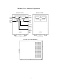
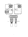
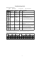
HI-AVR
High-frequency Automatic AC Voltage Regulator
AR-1K/AR-3K/AR-5K
AR-7.5K/AR-10K/AR-15K/AR-20K
USER’S MANUAL
CONTENTS
1. The HI-AVR Maintenance
Page 2
2. Introduction Characteristics
Page 3
3. Functions Instruction
Page 4
4. Machine View/ Indicator Explanation
Page 5
5. Operating Procedures
Page 7
6. The Operation Procedures of Maintenance
Page 8
By Pass Switch
7. Trouble Shooting Guide
Page 9
8. Specification
Page 10
1
The Protection and Maintenance of HI-AVR
1. Please clean and maintain the HI-AVR periodically to keep from dust for
lasting machine life.
2. Please use soft cloth for wiping, and please don’t use sandpaper as detergent.
3. Please check every kind of connection wires every month periodically to
prevent the loosing or abrasion.
4. Please place the unit on a flat or even surface.
5. This unit should be situated with well-ventilation, please allow at least 10 cm
clearance from the rear front, left and right side, and these ventilation
openings of right and left front , and rear line should never be blocked.
6. Please avoid the direct sunshine, rain or moisture place.
7. Keeping the unit away from fire and high temperature to avoid overheat.
8. Please don’t place any object on the top.
9. Avoiding the installing place that contains the corrosion gas.
10. Operating temperature is between 0OC and 40OC.
2
Introduction
To react with the uprising power environment protection notion, so we
provide you a regulator designed to meeting environment protection concept :
green power HI-AVR.
The regulator on the open market is divided into relay type, servo motor type and
electronic type. And the electronic type could also be devided into full-electronic
type and electronic-jumper type. All of them are large size, slow response, bad
load characteristics, and high price. The announced AR series are the
full-electronic high-frequency linear regulators that improved the defects
mentioned above. The AR series are small but economic and steady regulators,
and they are electricity saving and steady electric power equipment for
customer’s use.
Characteristics / Purpose
The AR series have the first new design structure and circuit in the world. The
central is controlled by CPU, therefore the stability and response speed of the
new HI-AVR are much quicker than ever. There are output high or low voltage
protection HI-AVR and maintained by-pass switch HI-AVR for another choice.
The product with excellent performance could be applied to home-using
appliances (including refrigerator, television), general OA machine (including
copying machine), all kinds of tooling machines (including CNC tooling
machine), and all kinds of precise apparatuses (including medical, science,
military apparatuses).
INPUT
OUTPUT
REGULATOR
RECTIFIER
INVERTER
HI-AVR Function Schema Diagram
3
Functions Instruction
CB1: no-fuse circuit breaker.
Main power switch.
CB2: no-fuse circuit breaker. (option)
Total output switch.
CB3: no-fuse circuit breaker. (option)
Maintenance bypass switch.
※ Please remember that CB3 is used only for service technician.
Non-maintenance personnel must not open it to use, otherwise, HI-AVR
could be break down because of improper operating.
ON push switch (red button): (option)
Controlling the output (ON) action.
OFF push switch (green button): (option)
Controlling the output (OFF) action.
SW1 by-pass switch: (option)
ON (1): HI-AVR (INV) no action, so the output has no voltage stability function.
OFF (0): HI-AVR (INV) action, so the output voltage is steady.
LED Indicators:
Green LED light shows that HI-AVR is in normal status.
Red LED light shows that HI-AVR is in abnormal status.
Voltage and current indicator: (There is no current meter indication below
2KVA).
Voltage meter (V) indicates the output voltage.
Current meter (LOAD %) indicates the output current consumption percentage.
Warning sound:
There is warning sound as CB1 is opened; this means HI-AVR is activated then
begins the self-test about 2.5 seconds.
If there were still warning sound after 2.5 seconds from activating CB1, this is
the abnormal status.
4
Machine View / Indicator Explanation
FRONT VIEW
FRONT VIEW
Output
voltage
Output
current
indicator
Output
ON
switch
Output
OFF
switch
Abnormal
indicator
(Red LED)
Normal
indicator
(green
LED)
Maintenance By-pass Model
Standard Model
AR-7.5K / 10K / 15K SIDE VIEW
5
REAR VIEW
REAR VIEW
Fan
SW1
by-pas
s
switch
CB1
CB2
CB3
Maintenance By-pass Model
I/G
Standard Model
I/N
I/L O/G O/N
I/L
HI-AVR steady
voltage output
AC input
6
Operating Procedures
I. Preparation before operation:
Checking the input power is correct or not, then closing all switches (including
every load).
II. [standard Model]
a. Starting procedures:
1. Turn on CB1 no-fuse circuit breaker up to ON position. At this time,
buzzer warning sounds about 2.5 seconds and abnormal LED (red LED)
light on about 2.5 seconds.
After this abnormal LED (red LED) would be extinguished and normal
LED (green LED) light on.
2. Using TURE RMS voltage meter to measure the O/P N, L on the
terminal block, and comparing this value with the reading value of
indicator voltage meter on front panel for similarity confirmation. If the
output voltage is correct, HI-AVR is activated successfully.
3. Opening the electric power switch on equipment, and the consumption
power is shown on the indicator current meter on front panel.
b. Stopping procedures:
1. Closing the power switch of every load.
2. Turning off the CB1 no-fuse circuit breaker down to OFF position.
III.[Maintenance By-pass Model]
a. Starting procedures:
1. Turning on the SW1 switch of rear panel to AVR position (0).
2. Performing the same step 1 of standard model.
3. Turning on the CB2 no-fuse circuit breaker up to ON position.
4. Pushing the red button (ON) on front panel, then there is output voltage.
5. Performing the same step 2 of standard model.
6. Performing the same step 3 of standard model.
b. Stopping procedures:
1. Performing the same step 1 of standard model.
2. Pushing the green button (OFF) on front panel, although there is no
output voltage, the HI-AVR is still in action.
3. Turning off the CB1 no-fuse circuit breaker to OFF position for closing
the HI-AVR thoroughly.
4. Switching the CB2 no-fuse circuit breaker to OFF position.
7
The Operation Procedures of Maintenance Bypass Switch
Starting procedures:
1. If the HI-AVR is abnormal, switching the SW1 of rear panel to Bypass
position (1), then the power supplied from bypass circuit.
2. Opening the protection cover of CB3.
3. Turning ON the maintenance by-pass CB3 no-fuse circuit breaker.
4. Turning OFF the total output no-fuse circuit breaker CB2.
5. The HI-AVR could be maintained But the CB2 must not be open at this
time, or the HI-AVR could be easily to cause break down.
After maintaining, the power of HI-AVR supplied from bypass circuit could be
changed to from stable voltage status, so HI-AVR could be back to normal
status by following sequential actions:
1. Confirming the SW1 bypass switch is on BYPASS position (1).
2. Activating the total output no-fuse switch CB2.
3. Closing the maintenance bypass no-fuse switch CB3
4. Turning on the SW1 bypass switch to AVR position (0), then closing the
protection over for keeping from machine burned out because of the
imprudent touch by non-service personnel.
8
Trouble shooting Guide
HI-AVR Status Indicator:
z:extinguish
:ligh
LED status
green red
z
z
z
z
z
z
9: warning buzzer
Voltage Meter
Reading
110V or 220V
±2.5%
Current Meter
Warning
Reading
Sound
The load %
indicated
r
under 100% area.
110V or 220V The load %
9
indicated
±2.5%
under 100% area.
Input voltage is 1.The load %
the same as the
indicated
output voltage.
under 100%
area.
9
2.The load %
indicated
over 100% area.
None
None
9
None
None
r
Input voltage is The load %
the same as the indicated
output voltage. under 100% area.
r:no warning buzzer
Process Methods
Normal
If the output current exceeds the rating current,
please reduce load to below the 90% of safety
rating current.
1. If HI-AVR overheats, please check the
environment is hard or not.
2. If the overload causes overheat, please
improve environment or reduce load to
below the 90% of the safety rating current.
If the input voltage exceeds or below the rating
voltage, this machine is normal; if not, please
notify the service personnel
(MB model).
Ensuring CB3 is closed as OFF and CB2 is
activated as On, then pushing the red button
once, if there is still no voltage, please notify
the service personnel (MB model).
1. Check SW1 to position (1).
2. Please notify the service personnel.
r
The materials linked on HI-AVR must meet the following specification to ensure the
safety as equipping them on HI-AVR.
Output rating
VA current
110V 220V
1K 6.4A 3.2A
2K 12.7A 6.4A
3K 19.1A 9.6A
5K 31.8A 15.9A
Output rating
VA current
110V 220V 110V 220V
110V 220V
16 16
1.25 1.25 7.5K 47.7A 23.7A
12 16
3.5
1.25 10K 63.6A 31.8A
12 14
3.5
2
15K 95.5A 47.7A
8
12
8
3.5 20K
63.6A
AWG
mm2
9
mm2
AWG
110V
6
6
4
220V
10
8
6
6
110V
14
14
22
220V
5.5
8
14
14
Specifications
Power
rating
Model
P.F. = 0.7
AR-1K AR-3K
1KVA/ 3KVA/
700W 2.1KW
AR-5K
5KVA/
3.5KW
AR-7.5K AR-10K AR-15K AR-20K
7.5KVA/ 10KVA/ 15KVA/ 20KVA/
5.25KW 7KW
10.5KW 14KW
50 HZ or 60 HZ
110V, 115V, 120V, 220V, 230V, 240V, 1∅ 2W 1∅ 3W
+-15% (Option +-25%)
110V, 115V, 120V, 220V, 230V, 240V, 1∅ 2W 1∅ 3W
Typical +-1%
Frequency
Voltage Phase
Range
Voltage
Voltage
Regulation
Frequency
50 Hz or 60 Hz
Output
Efficiency
>95%
Power Factor
+-0.7
Harmonic
<3% of T.H.D. at linear load
Distortion
Control Method
SPWM (Sinewave Pulse Width Modulation)
Master Control
IGBT & MOSFET inside
AVR
Component
Working
20KHz
Frequency
。
Working Temperature
0 C~40。C
Conditions Relative
0% - 95% Non-condensing
Humidity
Over voltage
Option
Over load
Option
Protection
Surge Absorbing
Varistor
Noise Filter
E.M.I. Filter or LC Filter
O/P Voltage
9
Indication
Indication O/P Current
9
r
Indication
Lights
Normal : Green Abnormal : Red and Warning Buzzer
Maintenance Maintenance
Option
Bypass Switch
Size
W*D*H (mm) 120*200
280*420
244*392*342
*320
*390
Weight
Net weight
7.5kgs
15kgs
20kgs 24kgs
27.5kgs 32kgs
40kgs
Input
Specifications are subject to change without notice.
660-0000-036
10