1
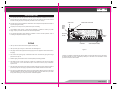
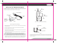
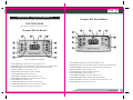
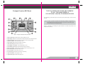
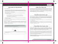
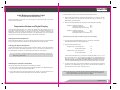
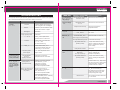
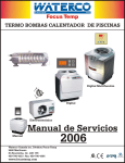
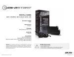
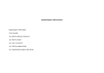
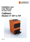
Portapac Inst/ Operation Owners Manual
Code No: (63813896) 10/ 2005
- Dimension : 279mm(H) X 210mm(W) = A4 size
Date: 05/ 10/ 2005
Owners Manual
PORTAPAC
WARNING
This equipment must be installed and serviced by an authorised technician. Improper installation can
create electrical hazards which could result in property damage, serious injury or death. Improper
installation will void the warranty.
Waterco Limited ABN 62 002 070 733
OFFICES - AUSTRALIA
NSW (HEAD OFFICE) Sydney
VIC/ TAS
OFFICES - OVERSEAS
Tel : +61 2 9898 8686
Fax : +61 2 9898 1754
USA
Phoenix
Tel : +1 623 434 4703
Fax : +1 623 434 4704
Melbourne Tel : +61 3 9879 5141
Fax : +61 3 9879 5143
USA (Baker Hydro) Augusta
Tel : +1 706 793 7291
Fax : +1 706 790 5688
WA
Perth
Tel : +61 8 9273 1900
Fax : +61 8 9273 1999
CANADA (Focus Temp) Quebec
Tel : +1 450 796 4333
Fax : +1 450 796 4365
QLD
Brisbane
Tel : +61 7 3299 9900
Fax : +61 7 3299 9911
NEW ZEALAND
Auckland
Tel : +64 9 525 7570
Fax : +64 9 525 6580
SA/ NT
Adelaide
Tel : +61 8 8244 6000
Fax : +61 8 8244 6011
MALAYSIA
Kuala Lumpur Tel : +60 3 6250 8169
Fax : +60 3 6250 8175
ACT (Distributor)
Canberra
Tel : +61 2 6280 6476
Fax : +61 2 6239 1395
CHINA
Guangzhou
Tel : +8620 8335 1107
Fax : +8620 8335 1114
INDONESIA
Jakarta
Tel : +62 21 4585 1481 Fax : +62 21 4585 1480
Notice to Installer
This manual contains important information about the installation, operation and
safe use of this product. Once the product has been installed this manual must
be given to the owner/ operator of this equipment.
EUROPE (Lacron) United Kingdom Tel : +44(0) 1795 521 733 Fax : +44(0) 1795 522 085
(63813896) 10/ 2005
www.waterco.com
IMPORTANT SAFETY INSTRUCTIONS
When installing and using this electrical equipment, basic safety precautions should always be
followed, including the following:
READ AND FOLLOW ALL INSTRUCTIONS
CAUTION
RISK OF ELECTRIC SHOCK
Installation or repairs should be carried out by the manufacturer, service agent or a similarly
qualified person in order to avoid hazards.
Work may only be performed on this product after disconnecting it from the mains power.
WARNING
RISK OF ELECTRIC SHOCK
Connect only to a grounding type receptacle protected by a ground-fault circuit-interrupter (GFCI) or
a Residual Current Device (RCD) with a rated residual current not exceeding 30mA. Contact a
qualified electrician if you cannot verify that the receptacle is protected by a GFCI or an RCD.
WARNING
CAUTION
In the event the Portapac’s Over Temperature Switch is activated and the Portapac shuts down, the
cause of the fault MUST be fixed before the Over Temperature Switch is reset. The Over
Temperature Switch will activate if the water in the Portapac reaches 45°C. The activation of this
safety switch indicates a significant fault with the system. If the fault is not fixed before resetting, the
Over Temperature Switch will activate again.
To reduce the risk of injury, do not permit children to use this product unless they are closely
supervised at all times.
To reduce the risk of Electric Shock, if the electrical power supply cord is damaged it must be
replaced immediately by the manufacturer, service agent or similarly qualified person in order to
avoid hazard.
15 Amp units must be connected to a 15 Amp power supply.
SAVE THESE INSTRUCTIONS
The power supply cord should be located and protected to prevent the cord from sustaining damage
from lawn mowers, hedge trimmers and other equipment. Do not bury cord.
Do not run this product on an extension cord. Damage to the electrical components may result.
Install in a well ventilated area. Do not bundle excess power supply cord near items that generate
heat. Property damage, serious injury or death may result.
The products mentioned in this manual are specifically designed to work with clean water at a
temperature between 15°C (59°F) and 40°C (104°F).
Any modification of this product requires the prior consent of the manufacturer. Original
replacement parts and accessories authorised by the manufacturer ensure a high level of safety.
The manufacturer accepts no liability for the damage and injuries caused by unauthorised
replacement parts and accessories.
PORTAPAC
Contents
GENERAL INFORMATION
The Waterco Limited portable spa pool and spa bath pumps have been designed to be simple to
install and easy to operate.
2
3
PIPING
3
INSTALLING THE TEMPERATURE SENSOR
5
INSTALLING THE AIR SWITCH
7
INSTALLING THE TOUCH PAD
7
OPERATION - AIR SWITCH MODELS
MANUAL OPERATION
OPERATION - TOUCH PAD MODELS
THE TOUCH PADS
8
8
9
The Air Switch Model Portapacs (Demand & Demand Elite) are supplied WITHOUT Air Switches.
There are many different styles of Air Switch available and as a result the Air Switches are sold
separately.
Depending on the selected pump model, a maximum of either 10A or 15A can be drawn by the unit.
Waterco Limited portable spa and spa bath pumps are designed to comply with Australian Standard
AS/ NZS 3136 and AS/ NZS 3350-2-41.
The models of Portapac covered by this manual include.
9
Portapac SSC Air Models
9
Portapac SSC Boost Models
10
Portapac Premium SSC Boost
11
Portapac Demand 10A
SWITCHING ON THE PORTAPAC
13
Portapac Demand Elite 15A
USING THE TOUCH PAD
14
Pump Mode and Indicator Light
14
Demand Mode and Indicator Light
14
Air Mode and Indicator Light
15
Boost Mode and Indicator Light
16
Auxiliary Button and Indicator Light
16
Light Button and Indicator Light
17
Temperature Button and Digital Display
17
Loss of Power
19
EMPTYING THE SPA
19
OVER-TEMPERATURE DEVICE (45˚C)
19
WATER CHEMISTRY
20
TROUBLESHOOTING
21
TECHNICAL SPECIFICATIONS
24
Air Switch Models
Touch Pad Models
Portapac SSC Air 10A
Portapac SSC Air 15A
Portapac SSC Boost 10A
Portapac SSC Boost 15A
Portapac Premium SSC Boost 10A
Portapac Premium SSC Boost 15A
PORTAPAC
02
INS
STALLATION
The pumps have been designed to fit within the surroundings of a portable spa and are supplied
with flexible electrical cable and plug for single phase power supply connection.
INSTALLATION
It is important for trouble free operation that the pump is adequately ventilated. Ensure there is
at least 100mm free space behind the motor fan cowl for free airflow to cool the motor. Ensure
the area enclosing the pump is adequately ventillated so hot air can escape.
The spa pump must be accessible for maintenance and to adjust the temperature thermostat on
top of the pump (when fitted).
The pump must not be put into a position that is prone to flooding.
The installation must conform to local electrical standards or guidelines. Contact your power
supply company for further information on electrical requirements.
The external temperature sensor MUST be installed. To ensure accurate operation, refer to
"Installing the Temperature Sensor" on page 5.
PIPING
TIME CLOCK
AIR BUTTONS/ TOUCHPAD
NICHE
FILTER
W/BY.
PASS
ISOLATION
VALVES
DOUBLE
LOOPS
PORTAPAC
AIR BLOWER (OPTIONAL)
1. Use only the PVC half unions that are supplied with the pump.
2. Use only 40mm pipe, or larger, for both suction and discharge lines.
3. The piping must be well supported to reduce piping load on the equipment and excess stress on
the piping.
4. This is NOT a self priming pump. Install below water level. Install suction piping without high
points that can trap air.
5. Install the piping with the least number of bends (elbows) and fittings possible.
Figure 1
If a blower is installed it is essential that steps are taken to ensure water does not enter the blower.
An electrical hazard may result. A double loop fitted prior to the blower is recommended. Consult
your blower manual for further details.
6. The Waterco pump must be connected to at least two (2) separate suction points in the water
via a common line, no less than 600mm apart. Check local codes for proper installation
requirements.
7. The spa outlets (pump suction line) should be located as far below the water level as possible to
prevent the pump from running dry. Spa inlets should be located well below the water level.
PORTAPAC
04
8. If the pump is installed below water level, shut off valves (either Waterco diverter or ball valves)
should be installed on both the suction and discharge piping to prevent back flow of pool water
during routine servicing of the pump and other circulation equipment.
INSTALLING THE TEMPERATURE SENSOR
All models of Portapac are packaged with a temperature sensor and sensor housing. The
temperature sensor/ probe is an integral part of the operation of the Portapac. If the sensor and its
housing are not installed correctly the Portapac will not function properly.
SPA WALL
SPA
INSULATION
GASKET
NUT
SENSOR CONNECTOR
SENSOR HOUSING
SENSOR
WIRE
SENSOR WIRE
SENSOR
WATER MUST
FILL THIS
AREA TO GET
AN ACCURATE
READING
SENSOR GOES IN
FROM THE BACK
SENSOR
HOUSING
NUT
Figure 3 - Side view of installed sensor and housing
Figure 2: Temperature Sensor and Housing
1. Mark a place for the sensor housing on the wall of the spa, 300mm below the water level where
the water flows freely.
SENSOR/ HOUSING
2. Cut away a reasonable amount of insulation on the spa to enable access for installation.
PORTAPAC
CONTROL BOX
3. Drill a 30mm diameter hole in the spa wall.
4. Place the gasket on the sensor housing and insert the housing through the hole in the spa wall.
Place the nut on the housing and tighten.
SPA
PORTAPAC
NOTE: It may be necessary to secure the sensor in the housing. Avoid placing anything on the
metal part of the temperature sensor as this will affect the accuracy of the readings.
6. For Portapac Air Switch Models you will need to connect the sensor connector to the side of the
Portapac control box. There is only one socket that it will fit in to. The design of the probe
connector is such that it will only fit into the socket when you have it the correct way around.
SENSOR WIRE
Figure 4
Do not allow the probe wire to touch the ground, metal or the motor of the pump as this can affect
the temperature reading. Make sure the probe wire is not bundled up. The result should look similar
to that shown in Figure 4.
PORTAPAC
06
5. Insert the probe into the housing making sure it is pushed all the way in. The result should look
similar to that shown in Figure 3.
INSTALLING THE AIR SWITCH
As there are many varieties of Air Switch available for the Portapac, the exact installation of the Air
Switch cannot be explained. However, there are a few things to consider for all Air Switches.
1. The Air Switch must be connected to the clear flexible tube supplied with the Portapac.
2. The clear tube must remain free of kinks and blockages.
3. The Air Switch should be no further than 2.8m from the Portapac.
OPERATION – AIR SWITCH MODELS
Demand & Demand Elite
MANUAL OPERATION
These Portapacs are controlled by an adjustable thermostat and a four-stage sequential “air
switch”. The button for the air switch will most likely be located on the spa coping or timber cabinet.
When switched on at the power supply the Portapac will default into Demand Mode. Demand Mode
is also the 4th press of the button.
Fully depress the button and the Portapac will change modes in the following sequence,
1st press is STANDBY Mode.
Power is supplied to the Portapac but the pump, heater and blower are switched off. The
power indicator light on the side of the control box on the Portapac will glow.
INSTALLING THE TOUCH PAD
2nd press is PUMP Mode.
The Pump is switched on. The heater will automatically switch on whenever the spa
temperature drops by approximately 2°C below the preset temperature. The preset
temperature is set using the dial on the control box of the Portapac.
3rd press is BLOWER Mode.
The blower is switched on and the heater is switched off. The pump remains operational.
The heater is switched off to compensate for the extra current drawn (power usage) by the
blower. This is commonly called “load shedding”.
4th press is DEMAND Mode.
The blower is switched off. When the spa temperature drops by approximately 2°C both the
pump and heater will automatically switch on to heat the spa to the preset temperature. The
preset temperature is set using the dial on the control box of the Portapac.
The Demand Mode is best suited for when the spa is not being used. The Demand Cycle
will keep the water at the desired temperature 24 hours a day, 7 days a week. In most spa
pool applications this is more efficient than letting the water cool to room temperature and
then heating it up when you want to use it again.
Note: The use of a spa cover or blanket will help maintain spa temperature and greatly improve
the efficiency of the Portapac.
WARNING
Do not run the Portapac dry. Doing so may cause serious damage to the pump and will void
the warranty.
PORTAPAC
08
These model Portapacs are fitted with a touch pad rather than an air switch to control the system.
The Portapac Touch Pad should be located on the ledge of the spa, no further than 1.2m from the
Portapac. The hole for the touch pad should be made to 46mm x 101 mm.
OPERATION – TOUCH PAD MODELS
SSC Air 10A & 15A, SSC Boost 10A & 15A, Premium SSC Boost 10A & 15A
Portapac SSC Boost Models
THE TOUCH PADS
Please identify your model touch pad from the following.
Portapac SSC Air Models
Figure 6: Portapac SSC Boost Touch Pad
Figure 5: Portapac SSC Air Touch Pad
1. Power indicator light. Indicates power is being supplied to the unit.
1. Power indicator light. Indicates power is being supplied to the unit.
2. Digital display. Displays the Spa Temperature, Desired Temperature and Temperature Bias.
2. Digital display. Displays the Spa Temperature, Desired Temperature and Temperature Bias.
3. Temperature button. Adjusts the Desired Temperature and the Temperature Bias.
3. Temperature button. Adjusts the Desired Temperature and the Temperature Bias.
4. Pump on/ off button. Turns Pump Mode on or off.
4. Pump on/ off button. Turns Pump Mode on or off.
5. Pump indicator light. Indicates Pump Mode is operating.
5. Pump indicator light. Indicates Pump Mode is operating.
6. Heater indicator light. Indicates the heater is on.
6. Heater indicator light. Indicates the heater is on.
7. Demand Mode on/ off button. Turns Demand Mode on or off.
7. Demand Mode on/ off button. Turns Demand Mode on or off.
8. Demand Mode indicator light. Indicates Demand Mode is operating.
8. Demand Mode indicator light. Indicates Demand Mode is operating.
9. Air on/ off button. Turns blower on or off.
10. Air High indicator light. Indicates blower is operating on high.
9. Boost on/ off button. Turns ancillary unit (usually a blower or boost pump) on or off.
10. Boost indicator light. Indicates ancillary unit is on.
11. Air Medium indicator light. Indicates blower is operating on medium.
PORTAPAC
10
12. Air Low indicator light. Indicates blower is operating on low.
Portapac Premium SSC Boost
THE FOLLOWING SECTIONS ARE COMMON
TO ALL TOUCHPAD MODELS
OF PORTAPAC UNLESS OTHERWISE STATED.
After familiarising yourself with the layout of the touch pad (see previous pages), it is time to set up
your spa.
Note: It is always a good idea to be familiar with all the settings available. We suggest that you
instruct all the people who will use the spa on how to operate it as well, either by giving
them this manual or by showing them yourself.
Reading, understanding and following this guide should lead to trouble free operation of the
Portapac SSC Spa Pump.
Figure 7: Portapac Premium SSC Boost Touch Pad
1. Power indicator light. Indicates power is being supplied to the unit.
2. Digital display. Displays the Spa Temperature, Desired Temperature and Temperature Bias.
3. Temperature button. Adjusts the Desired Temperature and the Temperature Bias.
4. Pump on/ off button. Turns Pump Mode on or off.
5. Pump indicator light. Indicates Pump Mode is operating.
6. Heater indicator light. Indicates the heater is on.
7. Demand Mode on/ off button. Turns Demand Mode on or off.
8. Demand Mode indicator light. Indicates Demand Mode is operating.
9. Boost on/ off button. Turns ancillary unit (usually a blower or boost pump) on or off.
10. Boost indicator light. Indicates ancillary unit is on.
11. Aux on/ off button. Turns auxiliary unit on or off.
12. Aux indicator light. Indicates the auxiliary unit is operating.
13. Light on/ off button. Turns spa light on or off.
PORTAPAC
12
14. Light indicator light. Indicates the spa light is on.
SWITCHING ON THE PORTAPAC
1. Fill the spa with water.
2. Untangle the Portapac’s electrical cord, plug it into the electrical power supply and switch it on.
DO NOT bundle excess cord in the pump compartment. Overheating of the cord may result,
which could damage the equipment. The cord should be carefully located and protected to
prevent personal injury or accidental damage.
USING THE TOUCH PAD
The Portapac can switch between Pump Mode, Demand Mode, Boost Mode (Boost and Premium
Boost Models only) and Air Mode (Air Models only) at any desired time. When any mode of the
Portapac is active the water temperature will be displayed on the Digital Display (2), except when
you are altering the Desired Temperature or the Temperature Bias. To deactivate a mode when it is
operating, simply press the respective on/ off button. When all modes of Portapac operation are
disabled the Digital Display (2) on the touch pad will be blank.
3. The touch pad Power Indicator Light (1) will turn on and one of the following will occur (refer to
"Loss of Power" on page 19),
a. The Digital Display (2) will remain blank and nothing else will happen, or,
b. The Portapac will start running in Demand Mode and the Spa Temperature
will be displayed on the Digital Display (2).
4. The Portapac is ready for operation. Refer to “USING THE TOUCH PAD” on Page 14 for details
on operating the Portapac.
In the interests of personal health, it is advised that no person should stay in the warm spa for more
than twenty (20) minutes at a time.
Every once in a while it is a good idea to check that the temperature displayed on the Digital
Display (2) is the same as the water temperature when measured with a thermometer. If the
temperatures differ, the Temperature Bias must be altered. To do this, please refer to "Calibrating
the Portapac’s Temperature" on Page 17.
If you come across a screen that says SP1 or SP2, press the Demand button a few times
until the Digital Display (2) goes blank. These two settings are used for adjusting air
blower speed and are factory set. DO NOT change them.
Pump Mode and Indicator Light
Press the Pump Button (4) at any time to activate/ deactivate the Pump Mode. The PUMP Indicator
Light (5) will glow if the Pump Mode is active. After twenty (20) seconds, the heater and its indicator
light (6) will switch on automatically if the water temperature is lower than the Desired Temperature
(refer to “Changing the Desired Temperature” on Page 17). The heater and its indicator light (6) will
switch off once the Desired Temperature is reached.
If the Portapac is left to run continuously in Pump Mode for thirty (30) minutes, the Portapac will
revert to Demand Mode.
Premium SSC Boost Models Only: If a UV Light or Ozonator is connected to the Portapac (in the
correct GPO), it will switch on when the pump is switched on. Note that the maximum current that
can be drawn from this GPO is 0.5 Amps.
Demand Mode and Indicator Light
Pressing the Demand Button (7) will turn the Demand Mode on/off. While the Portapac is in
Demand Mode, the DEMAND Indicator Light (8) will glow. The Demand Mode is best suited for
when the spa is not being used. The Demand Cycle will keep the water at the Desired Temperature
24 hours a day, 7 days a week. In most spa pool applications this is more efficient than letting the
water cool to room temperature and then heating it up when you want to use it again.
When this mode is selected, the pump, heater and the heater indicator light (6) will operate
automatically until the water has reached the Desired Temperature. Once this temperature is
reached, the pump and heater will switch off until the water falls by one (1) to two (2) °C, at which
point the pump and heater will switch on again. The Demand Indicator Light (8) will glow regardless
of whether the pump and heater are operating or not.
Premium SSC Boost Models Only: If a UV Light or Ozonator is connected to the Portapac (in the
correct GPO), it will switch on when the pump is switched on. Note that the maximum current that
can be drawn from this GPO is 0.5 Amps.
PORTAPAC
14
WARNING
Do not run the Portapac dry. Doing so may cause serious damage to the pump and may
void the warranty.
Air Mode and Indicator Light
Boost Mode and Indicator Light
SSC Air Models Only
SSC Boost & Premium SSC Boost Models Only
To activate Air Mode, or to cycle between different types of Air Mode, press the Air Button (9). The
different types of Air Mode can be activated as follows,
To switch on/ off a blower or a secondary pump (if attached) press the Boost Button (9). The
BOOST Indicator Light (10) will glow if activated.
Note: The pump will be switched on and the heater will be switched off when the Air Mode is
activated.
1st Press: Turns the Blower on and the Heater off. The Blower will activate at the high
speed setting and the High Indicator Light (10) will glow.
Note: The pump will be switched on and the heater will be switched off when the Boost Mode is
activated.
After running the Portapac in Boost Mode continuously for thirty (30) minutes the Boost Mode will
be deactivated and the Portapac will revert to Demand Mode.
2nd Press: Switches the Blower to Med setting. The Med Indicator Light (11) will glow.
3rd Press: Switches the Blower to Low setting. The Low Indicator Light (12) will glow.
4th Press: Switches the Blower to Massage setting. The Blower speed will gently cycle
between High and Low settings creating a massage effect. The Low Indicator
Light (12) will glow and the High Indicator Light (10) will blink in this mode.
Auxiliary Button and Indicator Light
Premium SSC Boost Models Only
Press the AUX Button (11) to switch on/ off an auxiliary device, such as a radio, that is plugged into
the Portapac. The AUX Indicator Light (12) will glow when the device is on.
5th Press: Switches the Air Mode off.
After running the Portapac in Air Mode continuously for thirty (30) minutes the Air Mode will be
deactivated and the Portapac will revert to Demand Mode.
If the Pump or Demand Modes are operating and Aux is activated the heater will cut out. If Pump or
Demand Modes are in operation and both Aux and Boost are activated, the heater, pump and
sanitiser will cut out. After 30 minutes the pump will switch on, Aux will remain active and the heater
will switch off.
If you come across a screen that says SP1 or SP2, press the Demand button a few times
until the Digital Display (2) goes blank. These two settings are used for adjusting air blower
speed and are factory set. DO NOT change them.
WARNING
PORTAPAC
16
Do not connect a pump to this outlet. Damage to the pump or Portapac control circuitry may
result.
Light Button and Indicator Light
Premium SSC Boost Models Only
Press the Light Button (13) to switch on/ off the spa light. The Light Indicator Light (14) will glow
when the device is switched on.
3. If the temperatures are not the same, alter the Temperature Bias as follows,
a. Switch off the Demand Mode by pressing the Demand Button (7). Make sure all other
modes are switched off as well. Only the Power Indicator Light (1) should be lit. The
Digital Display (2) should be blank.
b. Determine the Temperature Bias that will give the correct Displayed Temperature.
Temperature Button and Digital Display
Example 1: Displayed Temperature
40°C
Thermometer Temperature
36°C
Existing Bias needs to be reduced by 4°C
The Temperature Button (3) allows you to change the Desired Temperature (ranging from 10°C to
40°C) and the Temperature Bias (-5°C to +5°C) of the Portapac. The Desired Temperature is the
temperature at which the heater will maintain the water while in operation. Calibrating the
Temperature Bias ensures the displayed temperature on the Digital Display (2) of the touch pad will
be the same as the actual water temperature when measured with a thermometer.
Example 2: Displayed Temperature
40°C
Thermometer Temperature
42°C
Existing Bias needs to be increased by 2°C.
Read through the next steps once before trying it out on the Portapac.
Viewing the Desired Temperature
Press the Temperature Button (3) once and the Desired Temperature will flash on the Digital Display
(2) on the touch pad. After five (5) seconds the Spa Temperature will be displayed again.
Changing the Desired Temperature
View the Desired Temperature (see above). While the display is flashing, pressing the Temperature
Button (3) will increment the Desired Temperature by one (1) °C at a time until it reaches 40°C. At
this point the display will reset to 10°C and the display will continue to count upwards.
Note: If you hold down the Temperature Button (3), the display will continuously count upwards
until you let go of the button.
Calibrating the Portapac’s Temperature
The following steps explain the simplest way of calibrating the Portapac.
c. Press and hold the Temperature Button (3) for ten (10) seconds. The Existing
Temperature Bias will blink on the Digital Display (2).
d. Adjust the Temperature Bias to suit.
Example 1 (cont): If the existing bias is
The new bias should be
0°C
-4°C
Example 2 (cont): If the existing bias is
The new bias should be
-3°C
-1°C
Press the Temperature Button (3) to increment the Temperature Bias by one (1) °C at a
time. If at the bias point of (+) 5°C the button is pressed again the Temperature Bias will
drop back to minus (-) 5°C. If the Temperature Button is not pressed for ten (10)
seconds the display will go blank and normal operation may resume. Alternatively,
to exit the Temperature Bias setting mode, press the Demand Button (8) three (3) times.
e. To check the bias setting, press the Demand Button (8) and check that the displayed
temperature on the Digital Display (2) is the same as the thermometer temperature. If
the temperatures are not the same, repeat the process.
1. Run the Portapac in Demand mode until the temperature displayed on the Digital Display (2) of
the touch pad is the same as the Desired Temperature.
Note: If you come across a screen that says SP1 or SP2, press the Demand button a few times
until the Digital Display (2) goes blank. These two settings are used for adjusting air
blower speed and are factory set. They should not be changed.
PORTAPAC
18
2. Using a thermometer, take the water temperature and compare your reading with that on the
display. Take note of the Desired Temperature and the Thermometer Temperature.
Loss of Power
WATER CHEMISTRY
If the power supply to the Portapac is lost, either by disconnecting it from the power supply or from
a “blackout”, when power is restored the Portapac will operate as follows,
1. Portapac was powered but no devices were running. The Portapac will start up as it was
before losing power.
2. Portapac was in operation (e.g. in Pump, Demand Modes etc.). The Portapac will start up in
Demand Mode.
EMPTYING THE SPA
If you intend emptying the water from the spa, disconnect the Portapac from the power supply (e.g.
at the wall socket) to ensure the Portapac will not be accidentally switched on while the spa is
empty. If the Portapac is run without water in the spa, serious damage or injury may result.
OVER-TEMPERATURE DEVICE (45°C)
The Over-Temperature device is a safety mechanism that ensures the water in the spa will not rise
above 45˚C. If, for any reason, the water inside the Portapac reaches 45˚C, the Over-Temperature
device will automatically shut down the Portapac and the Power Indicator Light (1) will begin
blinking. If this occurs, the cause of the problem must be fixed (refer to Troubleshooting on page
21). Once the problem is resolved, you must press the small RESET button located on the control
box on top of the Portapac. This should be done whilst the power to the Portapac is off and should
only be done after the water in the Portapac has cooled below 45˚C. After a short delay the
Portapac will be ready for operation again. If the problem has not been resolved, the OverTemperature device will automatically shut down the Portapac again.
UV STERILISER/ OZONATOR GPO
(Premium SSC Boost Only)
POWER SUPPLY CORD
All Waterco Limited portable spa and bath pumps have been designed to withstand the harsh
environments of spa or bath systems. Non corrosive (non metallic) materials are used extensively,
however metal parts are used in the heater element.
The heater element can be damaged due to incorrect chemical balance of the spa water. It is very
important to maintain the chemical balance of your spa. By doing so you will help prevent corrosion
of the heater element and ensure a long, trouble free life.
The chemical balance of water is a relationship between its pH, total alkalinity, calcium hardness
and water temperature. Testing kits are available to test water yourself or alternatively a
professional pool and spa shop can test your water to ensure that it is chemically balanced in
accordance with the Langelier saturation index.
Chlorine levels should not exceed 5.0ppm and have an ideal range of between 1.5ppm & 3.0ppm.
It is recommended that in water that exceeds 30°C, you should use bromine as an effective
sanitizer with a similar concentration to chlorine.
High levels of chlorine, bromine and ozone may corrode the heater element and stainless steel
components as well as the pump mechanical seal.
Extremely hard water above 300ppm of calcium with a high pH level can cause scaling of the heater
element. This will cause a reduction in heating efficiency.
NEVER ADD CHEMICALS TO YOUR SPA VIA YOUR SKIMMER BOX.
When adding chemicals always mix them into a bucket of water and evenly disperse the mixture
over the spa surface.
The water must be maintained at all times to the following
pH Level
7.2 - 7.8
Total Alkalinity
80 - 150 ppm
Calcium Hardness
150 - 300 ppm
Langelier Saturation Index
-0.2 to +0.2
Failure to meet these requirements may void the warranty.
OVER-TEMPERATURE RESET
Figure 8: Portapac Control Box
WARNING
KEEP CHEMICALS OUT OF REACH OF CHILDREN.
WARNING
PORTAPAC
20
This safety device indicates a significant fault in the spa system and should not be ignored
or tampered with.
TROUBLESHOOTING
FAULT (cont)
The spa pump should only be serviced by qualified service technicians. However, some problems
can be checked and rectified by the owner before making a service call.
Over-Temperature
Device tripped shortly
after power-up
ACTION
No power
Check the flexible electrical supply
cord is plugged in and not damaged.
Blown fuse
Check the power circuit fuse or circuit
breaker has not blown or tripped.
RCD tripped
Reset RCD.
Pump impeller jammed
Call service.
Touch pad display
shows 00
Temperature Sensor
not connected.
Call service to connect the sensor.
Temperature Sensor faulty.
Heater will
not operate
Water level too low
Faulty element
Water temp too
low
Call service.
Rotate clockwise to increase temp.
Thermostat setting too low
(does not apply to touch pad models)
A strong smell of plastic will be
present if burnt out. Call service.
Air switch
Check air tube is connected and
not blocked/ kinked
(air switch models only).
Temperature sensor not
operating correctly
Check electronic touch pad is
connected to Portapac (touch pad
models only). If not, call service.
Properly secure sensor in housing
(refer to "Installing the Temperature
Sensor"). Call service to replace if
sensor is faulty.
Faulty element or switch
Call service.
Incorrect Temperature
Bias setting Touch pad models only
Change the Temperature Bias
(refer to “Calibrating the
Portapac’s Temperature”).
Temperature Sensor not
operating correctly
Properly secure sensor in housing
(refer to “Installing the Temperature
Sensor”).
Touch pad
Over-Temperature
Device tripped
(touch pad power
indicator light will
blink on touch pad
models)
Add water to operate pressure switch.
Motor burnt out
Touch pad desired temp too low
Constantly Flashing
Heater Indicator Light
(touch pad models)
Call service to replace the
Temperature Sensor.
Over-Temperature
Device tripped.
See “ Over-Temperature Device
tripped ” below.
Over-Temperature
Sensor not
properly connected.
Call service to check OverTemperature Sensor connections.
Water inside Portapac reached,
and stayed at, 45˚C
(spa water still cold)
Check for and remove blockages
in the filter and pipe-work.
Call service to check for
blockages in the impeller.
Press Over-Temperature RESET.
Water in spa reached 45˚C
(touch pad shows lower
temperature)
Properly secure sensor in
housing (refer to “ Installing the
Temperature Sensor ”).
Press Over-Temperature RESET.
Touch pad models-Recheck
Temperature Bias (refer to “ Calibrating
the Portapac’s Temperature ”).
Press Over-Temperature RESET.
Water temp too
high
Increase the desired temp.
Air switch models - Plug Temp Sensor
into side of control box or replace if faulty.
Touch pad models - Call service to
connect the sensor or replace.
Blower will
not start
No power
Motor burnt out
Check the flexible electrical cable is
plugged in and not damaged.
Plug another device into the blower
power supply and turn on to check
power point (eg radio or light).
Check if water has entered the blower.
If so, call service.
PORTAPAC
22
Portapac
will not run
POSSIBLE CAUSE
ACTION (cont)
Call service to connect or replace.
00
FAULT
(cont)
Over-Temperature Sensor not
connected or faulty
TECHNICAL SPECIFICATIONS
All electrical work is to be carried out by an Authorised Electrician. Under no circumstances
should you attempt repairs on the electrical components of Waterco Limited products unless
you are qualified to do so.
Max.
Amps
Demand
10
Demand Elite
15
Pump
HP
1
1.5
Heater
kW
1.6
2.4
Boost/ Air Max.
kW
1.6
2.4
Aux Max.
kW
X
X
Operating Temp
°C
20 - 40
20 - 40
SSC Air
10A
15A
10
15
1
1.5
1.6
2.4
1.6
2.4
X
X
10 - 40
10 - 40
SSC Boost
10A
15A
10
15
1
1.5
1.6
2.4
1.6
2.4
X
X
10 - 40
10 - 40
1
1.5
1.6
2.4
1.6
2.4
1.6
2.4
10 - 40
10 - 40
Premium SSC Boost
10A
10
15A
15
If the water temperature is below the operating temperature of the Portapac, the Portapac will run in
Demand Mode until the set temperature is reached.
PORTAPAC
24
If the Waterco Limited Product is within the stated warranty period and you experience faults
always contact your supplier or the nearest Waterco Limited branch for advice. Failure to do
this may void the warranty. Refer to Warranty Terms and Conditions supplied with the pump.
Model
00
WARNING