1
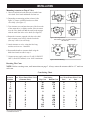
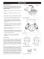
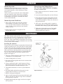
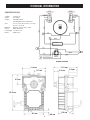
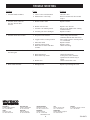
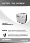
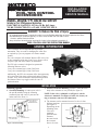
INSTALLATION
OPERATION &
SERVICE MANUAL
POOL/SPA CONTROL
ACCESSORIES
MODEL 3652607 FPI VALVE ACTUATOR
Suitable for Pool / SPA Equipment Applications
Electrical RatingS: 24 Volts, 50 Hz, 0.65 Amps.
TO BE CONNECTED TO A CLASS 2 CIRCUIT ONLY.
DANGER! To Reduce the Risk of Injury:
...do not permit small children to operate the control or use the Pool/Spa unless they are closely supervised at all times.
...test GROUND FAULT protection regularly. If it fails to reset, DO NOT USE THE POOL or SPA!
Contact a qualified service technician.
...always disconnect electricity before servicing this Control or the equipment connected to it.
READ, FOLLOW & SAVE THIS INSTRUCTION MANUAL
GENERAL INFORMATION
Valve Actuators are an important part of pool/spa
automation. They are used for changing the water flow
as required by a pre-set program or a remote manual
control.
The valve actuator will automate Waterco FPI valves, but
is also compatible with most 2 and 3 way diverter valves
for pools, spas and water features on the market.
The FPI valve actuator is designed to operate the
following Waterco valves:
2 way valve actuated type (4 bar) 50/65 mm.
3 way valve actuated type (4 bar) 50/65 mm.
Additionally, the FPI valve actuator offers the opportunity
to be retro-fitted into most existing pool and spa control
systems. They can be mounted in four different positions
and feature a three-way toggle switch for ease of
synchronisation.
INSTALLATION
Mounting Options
1.
Standard Plumbing of a three-port valve is
the port B (middle) being the incoming
(common) port and A and C ports are the
outlet ports (See figure 1).
Remove these four
(4) screws for
Standard Position
Port A
Water flows into or
out of the valve
Port C
Port B
(Common Port)
Figure 1. Standard Plumbing.
2. Standard Actuator Mounting position is when the main
body of the Actuator is over port B (See figure 2).
NOTE: If the valve is plumbed as in Figure 1 and the
Actuator is mounted as in Figure 2 below, the factory setting of Actuator cams need no adjustment.
3.
The Actuator can be mounted on top of a valve in four
different positions
(See figure 3).
Depending on the
plumbing of the
Port C
Port A
valve and
mounting
position of the
Actuator,
the cams inside
the Actuator
Port B
have to be reset.
(Common Port)
1
Figure 2. Standard Mounting.
INSTALLATION
Mounting Actuator on Top of Valve
I
1.Unscrew hold-down knob and remove handle from
valve shaft. Save knob and handle for later use.
2.Depending on mounting position selected, (See
figure 3), remove (4) Philip head screws from
valve body. (See figure 1).
II
A
C
A
C
B
B
III
I
3.Turn Actuator over and note that one of the four teeth
of the output drive is slightly smaller. Place Actuator
over the valve shaft such that the small tooth engages
with the small slot in the valve shaft. (See figure 4).
A
IV
C
A
B
4.Rotate the Actuator, engaged with the valve shaft
until Actuator posts line up with the four holes
(See step 2 above) in valve body.
C
B
Figure 3. Mounting Positions.
Place actuator on valve so small tooth aligns
with small slot.
SMALL SLOT
5.Attach Actuator to valve, using the four long
stainless steel screws - furnished.
6.Reassemble handle to Actuator shaft using the
hold-down knob set aside in step 1.
VALVE
7.Connect power supply cord to a CLASS 2 CIRCUIT
ONLY, rated 24V nominal, 4A or 100VA maximum.
SMALL TOOTH
BOTTOM
VIEW OF
ACTUATOR
Figure 4. Actuator Mounting.
Resetting The Cams
NOTE: Before resetting cams, read instructions on page 3. Always rotate the actuator shaft to “0” mark on
each cam.
Cam Setting Chart
Actuator Port, Water Enters/Exits ValveCam Setting
Port, Water Enters/Exits Valve
Position
(Common Port)
Top Cam
Bottom Cam
Port
or
Port
I*A
I
B
IC
II*A
90
90
180
180
180
B
270A
90A
90
B
C
C
B
C
B
0
0A
C
IIC
III*A
III
B
IIIC
IV*A
IV
B
IVC
90
90
270
0
0
180
270
180A
180
B
90A
270A
270
B
180A
0A
B
C
C
B
C
C
B
II**
*Two Port Valve Settings
**Standard Position
2
INSTALLATION
Resetting the Cams
Push Down to Rotate
Loosen Star
Locking Ring
NOTE: Refer back to Mounting Options on page 1,
standard plumbed and mounted values and Actuators
require no cam adjustments. Otherwise, follow
instructions below.
1.Find the mounting position of the Actuator in Figure 3,
Page 2.
2.Determine the COMMON and EXIT port(s) of the
valve.
3.Refer to table on page 2, find the proper cam settings.
4.Remove four screws and Actuator lid in order to gain
access to cam/motor compartment. (See figure 5)
Figure 5. Cam Adjustment.
5.Push down and rotate Actuator shaft so that the 0
degree mark lines up with arrow on switch housing.
(Bottom cam should now also line up with the arrow.
See figure 6.)
Final minor adjustments may be necessary
Lower
Cam
Upper
Cam
6.Reset cams, as defined earlier in Step 3 by loosening
the locking nut 1/4 turn counter clockwise and line up
specified marking on cams with arrows on switch
housings (See figure 6).
7.Retighten the locking nut. Check cam settings and
tightness of shaft assembly.
8.Power up Actuator(s) and check valve rotation and stop
positions. Make adjustments if necessary. Refer to
“Synchronisation” section below and Trouble Shooting
on page 6 if problems develop.
Left
Switch
Right
Switch
Figure 6. Cams.
9.Replace lid, make sure screws are tight and the
assembly is watertight. Install handle and test
operation.
Suction
Synchronisation
Spa
Return
Pool
Pool
Out of sync means: the Actuator is rotating in the wrong
direction in respect to its controller or another Actuator.
In order to synchronise the system, connect Actuator(s)
to its/their controller and observe its/their function. If an
Actuator is out of sync, flip the 3-position switch at rear
of Actuator to extreme opposite position. An example of
how actuators can be out of synchronisation is explained
below.
Figure 7 on the right represents the valves and actuators
for a pool/spa combination. The valve on the left (spa
on left and pool on right) is plumbed just the opposite as
the one on the right (pool on left and spa on right). If the
actuators are now activated one will turn to spa while the
other is turning to pool. Changing the cam settings within
the actuator will not correct this problem. To synchronise the actuators, flip the toggle switch at the rear of the
actuator (which is out of sync) to the extreme opposite
position. (See figure 8. Note: center position is OFF).
Figure 7. Synchronisation, Example.
AUTO
ON1
OFF
AUTO
ON 2
Figure 8. Synchronisation, Toggle.
3
On/OFF
Switch
on Back
of Actuator
Spa
OPERATION
Manual Operation
Manual Operation Without Power
During the normal operating season of a pool/spa
combination, there are times when the valves need
to be rotated manually, such as draining or filling
the pool or spa.
There are two ways to rotate the valves independent
from the controller, either electrically or manually.
If the system is operational, the electrical method is
recommended. If no power is available, the values
can be rotated manually.
Note: Turn filter pump OFF before attempting
to rotate Actuator shaft.
1. Move toggle switch at rear of Actuator to center
(OFF) position.
2. Loosen the hand-locking knob (4) four full turns.
3. Press firmly down on the locking knob in order
to disengage the Actuator gear train from valve
shaft. Now turn handle to rotate valve diverter to
any position desired.
Manual Operation With Power
1.Move toggle switch at the rear of the Actuator
from position 1 to position 2 (See figure 8) or
vice versa until desired rotation is reached. Move
toggle switch to center position to stop rotation
of valve diverter.
4. After service, the actuator must be returned to
the operating (drive) condition by pulling up on
the handle while turning it gently back and forth.
5. Tighten the locking knob on top of the handle
and return toggle switch back to its original
AUTO position (See figure 8).
2.Return toggle switch to its original AUTO
position after service.
MAINTENANCE
This Valve Actuator needs periodic service and depending on the type of valve it is connected to, it may also need
lubrication. The valve requiring lubrication comes with a
grease cap. Follow manufacturers instructions for servicing
such valves. Remember, a poorly maintained valve will lead
to early failure of the Actuator.
Servicing the Actuator
The gear train of the Actuator is permanently lubricated and
requires no further service. The seals however need periodic
attention. There are three seals that need to be greased once
a year. A lip seal is located under the Actuator, where the
shaft exits the lower housing and there are two ring seals in
the lid, where the shaft exits at the top. To lubricate these
seals, use only silicon base lubricant, suitable for the
purpose (See figure 9).
Unscrew Locking
Knob and
remove handle
Lubricate
Here
1.Turn power OFF to Actuator. (Move toggle switch at rear
of Actuator to CENTER position).
2.Loosen locking knob 4 to 6 turns.
3.Press down on locking knob and force the actuator shaft
into manual state.
4.Using a small brush, apply a small amount of silicon
lubricant around the now exposed portion of the shaft,
between the bottom of Actuator and top of valve.
5.Turn handle around once or twice to spread lubricant
evenly.
6.Pull upon handle and make sure the gears are now
engaged and the Actuator is in AUTO state.
Figure 9. Maintenance.
7.Remove locking nut and handle.
8.Apply a small amount of lubricant around the shaft, right
where it exits the lid. (The two ring seals are embedded
in the protrusion of the lid.)
9.Reinstall handle and place toggle switch to its original
AUTO position.
4
TECHNICAL INFORMATION
SPECIFICATIONS
Voltage:
24 Volts AC
Amps:
0.65 Amps
Torque:
250 inch pounds
(288 kilograms force centimeter)
Size:
L 7.12” (18.2 cm), H 4.50” (11.5 cm),
W 4.77” (12.2 cm)
Material:
Housing - Noryl: Gears - Steel
Grease:
MoS2 Lubricant
Cord length: 15’ (457.2 cm)
Rated:
Outdoor use
35 M F 120v
WIRING DIAGRAM
11.5 cm
11.4 cm
5.7 cm
3.2 cm
4.5 cm
16.5 cm
9.5 cm
5
.84 cm
6.6 cm
3.3 cm
TROUBLE SHOOTING
Problem
Cause
Solution
1. Actuator handle oscillates.
a. Lack of valve seal lubrication.
b. Obstruction in valve body.
Lubricate valve.
Remove actuator and valve lid and
inspect.
2. Actuator motor works but a. Broken actuator shaft.
Replace actuator.
the valve diverter does
not turn.
b. Broken valve diverter.
Replace valve diverter.
c. Actuator is in manual position.
Pull up on the handle white rotating
counterclockwise.
d. Actuator gear train is damaged.
Replace Actuator.
3. Actuator motor does not turn.
a No power to the actuator.
b. Toggle switch is in OFF position.
c. Motor has failed.
d. Failed or broken switch.
e. Both cams in contact with their
switches.
Check voltage between black
(common) and red then white wires.
Move toggle switch to AUTO position
1 or 2 as needed.
Replace actuator.
Replace switch.
Check cam setting.
4. Actuator rotates in one direction but
a. Broken or damaged switch.
not back again.
b. Bad connection(s).
c. Bad control relay switch.
d. Broken wire.
Replace switch.
Check all connections.
At the power source check the
operation of the control relay or
switch.
Check red and white wires.
5. Water inside Actuator.
Replace top lid and grease seals.
a. Damaged seals.
AUSTRALIA
SYDNEY (HEAD OFFICE)
Tel: +61 2 9898 8600
NEW ZEALAND
Auckland, New Zealand
Tel: +64 9 525 7570
UNITED KINGDOM
Sittingbourne, Kent. UK
Tel: +44 (0) 1795 521 733
USA
Augusta, Georgia, USA
Tel: +1 706 793 7291
CHINA
Guangzhou, China
Tel: +86 20 3222 2180
MALAYSIA
Selangor, Malaysia
Tel: +60 3 6145 6000
INDONESIA
Jakarta, Indonesia
Tel: +62 21 4585 1481
SINGAPORE
Nehsons Building, Singapore
Tel: +65 6344 2378
www.waterco.com
6
CANADA
St. Hyacinthe, Quebec, Canada
Tel: +1 450 7961421
158--01078