1
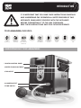
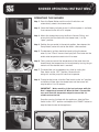
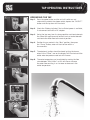
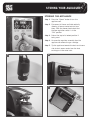
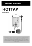
LOGiC
CERT 7795
Fully certified to
AS2658:2008
OWNERS MANUAL
Part No.
COMP825
INTRODUCTION
LOGiC
IT IS IMPORTANT THAT YOU READ THESE INSTRUCTIONS CAREFULLY
AND UNDERSTAND THE OPERATION & SAFETY FEATURES OF THIS
APPLIANCE. FAMILIARISE YOURSELF WITH THE APPLIANCE
BEFORE CONNECTING IT TO THE GAS CONTAINER.
KEEP THESE INSTRUCTIONS SAFE FOR FUTURE REFERENCE.
YOUR AQUACUBE® INCLUDES:
GAS
REGULATOR
WATER HOSE
AND PUMP
12V DC LEAD
AND CIGARETTE
CONNECTION
AC ADAPTOR
WATER FLOW
ADJUSTMENT
UNDERSTANDING YOUR AQUACUBE®
1.DIGITAL CONTROL PANEL
2.WATER FLOW ADJUSTMENT
3.TAP OUTLET
4.SHOWER OUTLET
5.FLOW SWITCH
QUICK CONNECT
FITTING
SILICONE
HOSE
SHOWER
HEAD
CARRY
BAG
INTRODUCTION
LOGiC
6.GAS REGULATOR
7. TAP OUTLET
8.UNIT POWER INLET
9.PUMP POWER OUTLET
10.WATER INLET
UNDERSTANDING YOUR AQUACUBE® DIGITAL CONTROL PANEL
1.ON BOARD BATTERY CHARGE LEVEL
7.OVER TEMPERATURE
2.BURNER OPERATING
8.OUTGOING WATER TEMPERATURE
3.INCOMING WATER
TEMPERATURE
4.OPERATIONAL OUTLET
9.OUTLET CONTROL
5. POWER ON/OFF
10.PUMP CONTROL
6. GAS/TEMPERATURE
GAS CONTROL
WARNINGS
LOGiC
CAUTION
DO NOT:Operate this appliance before reading the instruction booklet
DO NOT: Place articles on or against this appliance
DO NOT: Place chemicals or flammable materials, or spray aerosols near this appliance
DO NOT:Operate with panels, covers or guards removed from this appliance
DO NOT: Operate in an enclosed area without ventilation
DO NOT: Operate in a boat, caravan or tent
IMPORTANT
•
•
•
•
•
This appliance is designed to be used with a source water temperature of 20°C or below
The maximum temperature lift from the appliance is 25 to 30°C from the source
water temperature
For safety the appliance is designed to shut off the burner when the water temperature from
either of the outlets reaches 50°C
The average run time for the appliance from a fully charged battery is 20 to 30mins
before it will require recharging
The appliance can be operated whilst connected to AC or DC, however the battery will only receive
charge when pump is not operating. When the pump is off the battery will receive charge
THIS APPLIANCE IS NOT INTENDED FOR THE SUPPLY OF DRINKING WATER.
THIS APPLIANCE IS INTENDED FOR THE SUPPLY OF HEATED WATER FOR THE PURPOSE
OF WASHING AND CLEANING ONLY.
CHECK AND CONFIRM SAFE WATER TEMPERATURE BEFORE USING THIS APPLIANCE.
WATER FROM THIS APPLIANCE MAY BE VERY HOT.
WARNINGS
LOGiC
GENERAL WARNINGS
• T
his appliance shall only be used with the regulator
supplied with the appliance and must only be
connected to non-refillable 468g disposable
Propane Cartridges certified to DOT-39, UN1075.
• T
his appliance is to be stored in a dry & well
ventilated location free from direct sunlight. Do not
store when still connected to the cylinder. Make
sure that the cylinder is disconnected and is stored
in a well ventilated area, free from direct sunlight,
heat and ignition sources. If being stored indoors
ensure that the location complies with the standard
AS/NZS1596.
• T
his appliance must only be serviced by an
authorised service agent, return to your place
of purchase for service & repair.
DANGER!
• This appliance is designed for outdoor use only.
• D
o not use the appliance if it has a leak, worn,
deteriorated or damaged seals.
• H
andle with care even after brief use, always pick
up using the handle not the cylinder.
• It may be hazardous to attempt to fit other types of
gas containers or cartridges.
• Use only in well ventilated areas.
• T
his appliance shall only be used in an above
ground open air situation with natural ventilation,
without stagnant areas, where gas leakage and
products of combustion are rapidly dispersed by
wind & natural convection.
• D
o not use adaptors or modify appliance to fit other
connectors or cylinders.
• W
hen using this appliance children must be
supervised by an adult at all times.
• Never leave appliance unattended when operating.
• D
o not use as a cooking appliance or modify for
any other reason.
CARBON MONOXIDE HAZARD
• T
his appliance produces carbon monoxide which
has no odour. Using the appliance in enclosed
spaces for example, caravan, car, boat or mobile
home could cause DEATH.
• O
UTDOOR USE ONLY – The appliance must
be used outdoors only and is to be operated
no closer than 800mm from the sides and
800mm from above all combustible surfaces,
fabrics and flammable materials. Must only be
used on solid & stable horizontal surfaces made
from non-combustible or non-flammable materials
and should be protected from direct drafts and in a
well ventilated place.
• C
aution: Accessible parts may be very hot. Keep
young children away.
• Avoid twisting & kinking the Propane gas hose.
• If you smell gas immediately turn the gas off at the
cylinder and move the appliance & cylinder to a
well ventilated area outside, keeping well away from
sources of heat such as naked flames & pilot lights.
• D
o not attempt to move or relocate the appliance
when it is operating. Extinguish the burner &
allow to cool, disengage the gas cylinder then move
the appliance.
CHECKING FOR GAS LEAKS
• C
heck that all connections are tight and that the
gas cylinder connection has been tightened before
you turn the cylinder gas valve on.
• NEVER check for leaks with a flame or pilot light.
• U
sing soapy water coat all connections, if
bubbles appear turn the cylinder gas control off
and retighten the connection before re-testing.
• Inspect the appliance regularly for signs of wear,
leaks or incorrect operation. If symptoms such
as flaring of the burners, issues with lighting,
damages to hoses or connections or leaks from
seals or gas controls are identified do not
attempt to repair, contact Customer Service
on 1300 555 197.
• T
o check if gas remains in the cylinder, disconnect
from the appliance and hold the cylinder in a
vertical position then shake from side to side.
If there is a sound or a feel of liquid movement
inside the cylinder, the cylinder contains gas.
• W
hen changing gas cylinders ensure this is
conducted outside in a well ventilated location free
from people, animals & ignition sources such as
naked flames, pilot lights & electrical equipment
with heaters or elements.
SAFETY INSTRUCTIONS
LOGiC
SAFETY INSTRUCTIONS
This appliance must only be used in an above ground open air situation with natural ventilation, without stagnant
areas, where gas leakage is rapidly dispersed by wind and natural convection.
Any enclosure in which the appliance is used
should comply with one of the following:
(A) An enclosure with walls on all sides,
but with no overhead cover.
(B) Within a partial enclosure that includes an overhead
cover and no more than two walls.
(C) Within a partial enclosure that includes an overhead
cover and more than two walls, the following must apply:
(1) At least 25% of the total wall area is completely open.
1
(2) 30% or more in total of the remaining wall side, back
and front wall areas is open and unrestricted.
(3) In the case of balconies, 20% or more of the total wall
area must remain open and unrestricted.
1
2
1
2
Important
During operation ensure that all air
inlets & exhausts are kept free from
obstructions and closure.
AIR INLET
SAFETY FEATURES
LOGiC
IMPORTANT – This appliance is designed to be
used with a source water temperature of 20ºC or
below, if the temperature of the outlet water exceeds
45º -50ºC the burners will shut off and will only
relight once the outlet water temperature falls
below 45ºC.
This appliance is designed to raise the outlet water
temperature by a maximum (average) of 25ºC above
the source water temperature and can be adjusted
by the gas control. In the event that the temperature
lift is insufficient, simply run water through the
appliance once returning the heated water to the
source water reservoir. Run again through the
appliance until the desired temperature is reached.
SAFETY FEATURES
This appliance is equipped with the following safety
features:
• O
ver Temperature Sensor – the appliance will
not allow the burner to remain in operation once
the outlet water temperature reaches 45-50º, the
burner will automatically relight once the outlet
temperature falls below 45º.
• W
ater Flow Sensor – water must be flowing through
the system to allow the burner to ignite. In the case
that the water supply is restricted or ceases, ie. the
Flow Switch is in the “off” position, the burner will
be extinguished and will not relight until the water
flow recommences.
• T
ilt Switch – in the event that the appliance is
moved during operation or is being operated on an
unstable or non-solid surface the appliance will
shut down and must be switched off until a
suitable surface is located.
SETTING UP INSTRUCTIONS
LOGiC
1
SETTING UP
Step 1. Remove all components from the storage bag and place the appliance on a solid, non-combustible surface and straighten out all hoses to remove any kinks or twists.
Step 2. Check that the power switch is “OFF” then
connect the pump assembly to the water
inlet and the power lead to the outlet marked “PUMP”.
2
Step 3. Attach the gas cartridge to the regulator by
rotating in a “clockwise” direction then attach the regulator to the Aquacube.
Check for gas leaks with soapy water –
Do not use a flame.
If a leak is detected remove the gas
cartridge & retighten all connections,
then retest.
Step 4. Submerge the pump in a suitable reservoir of water, DO NOT use water direct from
rivers, lakes or the ocean. DO NOT use salt water with this appliance.
3
4
SHOWER OPERATING INSTRUCTIONS
LOGiC
1
OPERATING THE SHOWER
Step 1. Press the Power Button and the unit will switch on and
automatically selects the shower outlet.
Step 2. Check the Battery Indicator to see if sufficient power is available,
if not connect to the AC or DC adaptor.
2
Step 3.Attach the shower hose using the Quick Connect Fitting, and ensure that the Flow Switch on the shower head, is in the
“open” position.
Step 4. Position the gas control in the central position, then depress the Pump Button, water will start to flow within a few moments.
3
Step 5. The electronic ignition should be heard igniting the burner,
when lit, the “Flame” icon on the display will illuminate and the outlet water temperature read out will increase.
Step 6. Taking care to measure the temperature of the water from the shower head, the temperature can be adjusted by turning the gas control until the desired level is reached.
Open Flow regulation switch
4
Ensure Gas
control is
in central
position
5
Step 7. The water flow can be stopped at any time by sliding the
Flow Switch to the “OFF” position, the burner will
extinguish and the pump will continue to operate.
Step 8.To reignite the burner, slide the Flow Switch to the “on” position
and water will flow from the shower head and the burner will
reignite within 5 to 10 seconds.
IMPORTANT – Water remaining in the heat exchanger while the flow is stopped may become hot. When the flow is resumed the user must check the temperature output to ensure that it is
suitable and not too hot.
6
Once the user has finished with the appliance, slide the Flow
Switch to the “OFF” position and depress the “PUMP” button to
stop the flow of water to the appliance.
7
8
TAP OPERATING INSTRUCTIONS
LOGiC
1
OPERATING THE TAP
Step 1. Press the power button and the unit will switch on and
automatically selects the shower outlet, depress the “OUTLET”
button and the tap icon will illuminate.
Step 2. Check the “Battery Indicator” that sufficient power is available,
if not connect to the AC or DC adaptor.
2
Step 3.Swing the tap away from its storage position and locate towards
the side of the appliance and locate a basin or bucket beneath
and locate the water flow to the central position.
Step 4. Position the gas control in the “Max” position, then press
the “Pump” button, water will start to flow within a
few moments.
3
4
5
6
Step 5. The electronic ignition should be heard igniting the burner, when lit the “Flame” icon on the display will illuminate and the outlet water temperature read out will increase.
Step 6.
The water temperature can be adjusted by moving the flow valve between “Min & Max” as this will slow or increase
the water flow resulting in an increase or decrease in the
outlet temperature.
STORING YOUR AQUACUBE®
LOGiC
1
STORING THE APPLIANCE
Step 1. Press the “Power” button & turn the
appliance off.
Step 2.
Disconnect all hoses and hold vertically
allowing all excess water to drain from
them. With the shower head check that
the flow regulation switch is in the
“ON” position.
Step 3. Return the tap to its locked position if
being used.
Step 4. Unscrew the regulator assembly from the
appliance & remove the gas cartridge.
Step 5. Tip the appliance towards the back and to one
side to drain excess water from the heat
exchanger via the water inlet.
2
3
4
5
POWER AND CHARGING
LOGiC
1
APPLIANCE POWER & CHARGING
Step 1. The appliance is fitted with a 12V 2.5A/hr battery pack and can be recharged from either the AC or DC adaptors supplied.
Step 2. To recharge the appliance from either AC or DC the unit
must be switched on and the Battery Indicator illuminated.
2
Step 3.
Connect to the power inlet socket at the rear of the
appliance and the Battery Indicator will start to flash and move from “Red to Green” confirming that the battery is
now charging.
Step 4. AC: Connect the three (3) pin plug to a suitable outlet then connect to the appliance & switch on the AC outlet.
Step 5. DC: Connect the adaptor to the appliance and then connect to a suitable outlet via the cigarette lighter fitting.
3
4
5
•
DO NOT USE – AC to DC converters or modify the adaptors
supplied with the appliance.
•
Charge time from either power source is 4 hours, 50% battery
capacity can be reached after 2 hours however to maintain
battery life & condition it is recommended that the unit is allowed to charge for the full 4 hours.
•
IMPORTANT – If the appliance is not being used or is stored it must be recharged every three months to guarantee the battery life expectancy, failure to do so may result in
battery failure.
CARE GUIDELINES AND TROUBLESHOOTING
LOGiC
DISCONNECTING FROM CYLINDER
CARE INSTRUCTIONS
1. Check that the appliance is fully extinguished, the
gas cylinder control valve is in the fully “off”
position and all surfaces are cool.
Using warm soapy water with a mild detergent wipe
down all surfaces and areas of the appliance, taking
care not to allow water to enter the burner outlets.
DO NOT submerge the appliance in a sink or bowl.
DO NOT use abrasive cleaners or bleach.
2. Loosen the connection to the gas cylinder in a
clockwise direction.
SPECIFICATIONS
TROUBLE SHOOTING
This guide should be followed in case of failure of the
appliance to operate correctly. If symptoms persist
contact Customer Service on 1300 555 197.
DO NOT ATTEMPT TO REPAIR
OR MODIFY THE APPLIANCE
PROBLEM
CAUSE
Check that appliance is switched on
Check sufficient water is available
Water will
not flow from
shower head
Check that the pump is connected to the
appliance
Check that adequate DC power is
available
Check DC fuse in cigarette lighter fitting
Check that the shower flow water
regulator is in the open position
Check that gas cylinder is turned on and
that there is gas in cylinder
Burner will
not light
Check that the water is flowing from
shower head
Check that the water is not over
temperature
Check gas control
Water is not
hot enough
Check source water temperature
Cycle the water through the system back
in to the source reservoir then through the
appliance again
Part No:
COMP825
Water flow:
3 litres per minute (Average)
Inlet voltage:
12V DC - 5A
Size:
422 x 262 x 434mm
Weight:
8.5kg
Injector size:
0.66mm x 4
Consumption:
20.68Mj/hr
ERROR CODES
The appliance is fitted with a number of
operational & safety features that can be
identified by the following error codes in the
event that the unit will not operate:
E3: No Flame / Burner not lit
E6: Over Temp Shut Off
E7: Outlet Water Temp Exceed 48ºC
E8: Tilt Switch Activated
NOTES
Companion is distributed by Primus Australia Pty Ltd Bundoora Victoria 3083
www.companionleisure.com.au