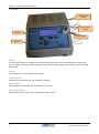
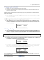
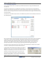
1
Oxygen & Carbon Dioxide Analyser
Model 1637-Mk II
Operators Manual
December 2013
TABLE OF CONTENTS
1. Overview & Specifications ........................................................................................ 3
1.1 Hardware Specifications ............................................................................................................................ 4
1.2 Product & Logging Specifications .............................................................................................................. 5
1.3 Heater Supply for the Oxygen Sensor ....................................................................................................... 5
1.4 Oxygen Sensor Impedance ........................................................................................................................ 5
1.3 Case ........................................................................................................................................................... 6
1.4 LCD Display ................................................................................................................................................ 7
1.5 Keypad ....................................................................................................................................................... 8
2. Quick Start ................................................................................................................ 9
2.1 Turning on the 1637-Mk II ......................................................................................................................... 9
2.2 Taking a Reading ........................................................................................................................................ 9
3. Setting up the Analyser .......................................................................................... 11
3.1 Operation of the Menu System ............................................................................................................... 11
3.2 Extended Display Mode ........................................................................................................................... 11
3.3 Setup Menu ............................................................................................................................................. 12
3.4 Configuration Menu ................................................................................................................................ 14
3.5 Product Selection..................................................................................................................................... 19
4. Alarms .................................................................................................................... 21
4.1 Sample Gas Related Alarms ..................................................................................................................... 21
4.2 Hardware Alarms ..................................................................................................................................... 21
5. Bluetooth PC Interface ........................................................................................... 23
5.1 Pairing Bluetooth Devices........................................................................................................................ 23
5.2 PC Interface Software .............................................................................................................................. 24
6. Calibration .............................................................................................................. 27
6.1 Oxygen ..................................................................................................................................................... 27
6.2 Carbon Dioxide ........................................................................................................................................ 28
7. Troubleshooting ..................................................................................................... 29
7.1 Analyser Information Screen ................................................................................................................... 29
7.2 Frequently Asked Questions.................................................................................................................... 30
December 2013
1637-Mk II O2 & CO2 Analyser
Operators Manual
1
© Copyright NOVATECH CONTROLS PTY LTD — 2013
This manual describes firmware version 1.04, December 2013
Neither the whole nor any part of the information contained in, or the product described in, this manual
may be adapted or reproduced in any material form except with the prior written approval of Novatech
Controls Pty Ltd (Novatech).
The product described in this manual and products for use with it are subject to continuous developments
and improvement. All information of a technical nature and particulars of the product and its use (including
the information in this manual) are given by Novatech in good faith. However, it is acknowledged that there
may be errors or omissions in this manual. A list of details of any amendments or revisions to this manual
can be obtained upon request from Novatech Controls Technical Enquiries. Novatech Controls welcome
comments and suggestions relating to the product and this manual.
All correspondence should be addressed to: Technical Enquiries
Novatech Controls Pty Ltd
309 Reserve Road,
Tel:
Cheltenham
Fax:
Victoria 3192
Email:
Australia
Website:
+61 3 9585 2833
+61 3 9585 2844
[email protected]
http://www.novatech.com.au/
Novatech Controls or their authorised dealers should carry out all maintenance and service on the product.
Novatech Controls can accept no liability whatsoever for any loss or damage caused by service or
maintenance by unauthorised personnel. This manual is intended only to assist the reader in the use of the
product, and therefore Novatech Controls shall not be liable for any loss or damage whatsoever arising from
the use of any information or particulars in, or any error or omission in, this manual, or any incorrect use of
the product.
Operators Manual
2
December 2013
1637-Mk II O2 & CO2 Analyser
1. OVERVIEW & SPECIFICATIONS
The Novatech model 1637-Mk II analyser is an instrument for measuring oxygen and carbon dioxide
concentration in a sample of gas. It has been designed for use in the food packaging industry where
products are packaged in a modified atmosphere of nitrogen and/or carbon dioxide.
The two modes of operation for the 1637 MK II device are ‘Sample & Hold’ and ‘Continuous Sampling’.
In Sample & Hold Mode, gas is extracted from the packaging via a sample line fitted with a hypodermic
needle. The needle penetrates the food packaging and the internal pump draws the package atmosphere
into the analyser for measurement. At the completion of each sample the oxygen and carbon dioxide levels
are shown on the display as well as an indication of whether these values are within the pre-determined
range.
In Continuous Mode gas is either drawn into the analyser using the internal pump, or pushed through the
analyser using process pressure. The oxygen and carbon dioxide content is continuously sampled and
displayed on the device LCD. For remote monitoring two isolated and fully programmable 4-20mA outputs
and 4 programmable relays can be configured to give indication of whether the gas levels are within range,
and that the device is functioning correctly.
The 1637-Mk II has several key features that offer the user flexibility and ease of operation
•
•
•
•
•
•
•
Sample & Hold or Continuous live monitoring of both Oxygen and Carbon Dioxide
Oxygen sensitivity down to 0.1ppm
Carbon Dioxide display resolution of 0.1%
Automatic calibration of oxygen & carbon dioxide in Sample & Hold Mode
2x fully programmable isolated 4-20mA outputs for remote monitoring in Continuous Mode
Internal sample log which can be reviewed or downloaded to a PC
Large LCD display with local indication of Oxygen & Carbon Dioxide during use
December 2013
1637-Mk II O2 & CO2 Analyser
Operators Manual
3
Chapter 1: Overview & Specifications
1.1 Hardware Specifications
Oxygen Range
1 part per million (ppm) to 100% oxygen.
Oxygen Response Time
<4 seconds with gas flow of 100cc per minute
Oxygen Accuracy
±1% of actual measured value with repeatability ±0.5% of measured value
Oxygen Display Resolution
30.0 to 100%
1.00 to 29.99%
100 to 10,000ppm
0.1 to 99.9ppm
±0.1%
±0.01%
±1ppm
±0.1ppm
CO2 Range
0 to 100%
CO2 Response Time
<8 seconds with gas flow of 100cc per minute
CO2 Accuracy
0 to 40%
40 to 80%
80 to 100%
±2%
±3%
±5%
Gas Connection
1/8” Swagelok®
Communications
Bluetooth® Wireless
Analog Outputs
2 isolated 0-20mA or 4-20mA field selectable
active outputs (DO NOT loop-power)
Analog Output Load
1000 ohm maximum
Alarm Relays
4 isolated programmable, failsafe (active open)
2A/240VAC, 2A/30VDC
Mains Voltage Supply
85 to 265VAC 50/60Hz
Mains Power
115W continuous, 500W maximum instantaneous
Warm-Up Time
5 minutes
Environmental Rating
Operating Temperature
Relative Humidity
0 to 50°C (32 to 120°F) or 0 to 45°C (32 to 110°F) with CO2 option.
5% to 95% (non-condensing)
Weight
6Kg
Dimensions
265mm (W) x 150mm (H) x 350mm (D) (10.5” x 6” x 13.75”)
Range of Analog Outputs
in continuous mode, field selectable from the following:
Oxygen
0 - 0.1% oxygen to 0 - 100% oxygen
Carbon Dioxide
0 - 1% to 0 - 100% carbon dioxide
Oxygen EMF
0 - 100mV to 0 - 1500mV
Operators Manual
4
December 2013
1637-Mk II O2 & CO2 Analyser
Chapter 1: Overview & Specifications
1.2 Product & Logging Specifications
Number of Products Stored
200 maximum
Product Name
~22 characters (alpha-numeric and symbols).
Exact number of characters is limited by the width of the display and
will vary.
Log Memory Capacity
3680 readings
Each reading records date, time, product, oxygen, carbon dioxide
1.3 Heater Supply for the Oxygen Sensor
CAUTION
The Oxygen sensor heater is supplied with mains voltage. This supply has electrical shock danger to
maintenance personnel. Always isolate the analyser before working with the oxygen sensor.
The sensor assembly must always be connected to earth.
The heater is supplied from the mains power directly, and the temperature is controlled to a set-point of
720°C (1320°F) after turn on.
1.4 Oxygen Sensor Impedance
The oxygen sensor impedance is an indication of the reliability of the oxygen reading. An oxygen sensor with
a high impedance value will eventually produce unstable erroneous signals. The analyser will check the
oxygen sensor impedance five minutes after the oxygen sensor reaches operating temperature. If the
analyser remains switched on it will repeat this check every 24 hours.
If the impedance is above 8kΩ then the impedance alarm will be triggered.
December 2013
1637-Mk II O2 & CO2 Analyser
Operators Manual
5
Chapter 1: Overview & Specifications
1.3 Case
Sample Gas
Inlet
Mains Power
Socket
Display
Needle Holder
Keypad
Display
The 1637-Mk II display is a 192x64 pixel monochrome graphical LCD. In standard operation it shows the
current oxygen and carbon dioxide readings, also previous sample readings, alarm status, product selected,
date & time.
Keypad
User interface for interacting with the analyser
Sample Gas Inlet
Sample line is attached to this 1/8” Swagelok® coupling
Needle Holder
Safe storage for the hypodermic needle when it’s not in use
Mains Power Socket
External mains power input; uses a standard IEC type connector.
Operators Manual
6
December 2013
1637-Mk II O2 & CO2 Analyser
Chapter 1: Overview & Specifications
1.4 LCD Display
O2
Oxygen current reading
CO2
2.03%
Oxygen –
Sample Reading
31.5%
20.95%
0.0%
001. Product 001 (1/5)
Product Name
CO2 - current
reading
CO2 – sample
reading
Product
Batch Count
Oxygen – current reading
The large number on the left hand side of the display shows the current oxygen reading.
Oxygen – sample reading
The small number on the left hand side of the display will show the last oxygen sample taken.
When a new sample is being taken the previous sample will be removed and the oxygen sample remains
hidden until the sample is complete.
Carbon Dioxide – current reading
The large number on the right hand side of the display shows the current carbon dioxide reading.
Carbon Dioxide – sample reading
The small number on the right hand side of the display will show the last carbon dioxide sample taken. Refer
to oxygen sample reading above for further information during sampling.
Product Number
This is the index number of the currently selected product
Product Name
A brief description of the product that is currently selected
Product Batch Count
This is a counter that can be used when testing in multiple sample batches. The first number is the current
sample; the second is the total number of samples to be testing in the batch.
December 2013
1637-Mk II O2 & CO2 Analyser
Operators Manual
7
Chapter 1: Overview & Specifications
1.5 Keypad
Display & Accept
Alarms
Product
Selection & Edit
Product Batch
Counter Reset
Display Sample
Log
Calibrate
Change Value
Up/Down
Enter / Accept /
Enter Setup Mode
Product Selection & Edit
A short press of the key will bring up the product list to allow the operator to select a product for testing.
Press and hold for ~2 seconds to bring up a product edit menu. A short press while in either product list or
product edit will take the analyser back to the main screen
Display Sample Log
A short press on the key will show the ‘data log summary’ of all the samples that have been taken. While in
setup mode this key functions as a ‘back’ key to navigate out of the menu system.
Change Value Up/Down
These two keys are used to change a selection or value.
Enter, Accept, Enter Setup Mode
The enter key is used to confirm a selection. A short press of this key from the analyser main screen will
enter the Setup Menu. For more details see Chapter 3.
Display & Accept Alarms
In the event of an alarm being triggered, the alarm LED will flash and the analyser will beep to alert the
operator. Press this key to acknowledge the alarm. If the alarm LED is on (not flashing), pressing the alarm
key will show the list of currently active alarms.
Product Batch Counter Reset
Press and hold for ~2 seconds to reset the product batch counter.
Calibrate
Press and hold this key for ~2 seconds to bring up the calibration selection menu. Use the up/down keys to
select which calibration to perform, press enter to perform calibration, or calibrate again to exit without
making any changes.
Operators Manual
8
December 2013
1637-Mk II O2 & CO2 Analyser
2. QUICK START
2.1 Turning on the 1637-Mk II
1. Plug the power lead into the analyser and the mains socket.
2. Turn on the power, noting there is a separate power switch on the side of the analyser where the
power lead socket is located.
The display will light up and show the Novatech company logo along with software version, serial number,
and last calibration date.
3. Screw the sample line onto the 1/8” Swagelok® tube connector above the mains socket on the right
hand side of the analyser.
The oxygen & carbon dioxide sensors inside the analyser take approximately 5 minutes to stabilise ready for
sampling. During this time there will be no readings displayed on the device.
4. When the analyser is ready to sample it will alert the operator with a single loud beep, the display
should look like the below picture (if there is no Carbon Dioxide then it will only have oxygen in the
centre of the display)
O2
20.95%
-
CO2
0.0%
-
001. Product 001 (1/5)
2.2 Taking a Reading
5. Insert the hypodermic through a piece of septum into a food pack to commence a gas reading. The
numbers on the display should start changing immediately. Leave the needle in the pack for 5 to 10
seconds, or until the head space is nearly all evacuated.
Take care not to suck any food product or liquid into the sample line. Doing so may damage the analyser
and any damage caused by contamination will not be covered by warranty.
6. The display will show the oxygen and carbon dioxide readings in the large characters, the display will
say ‘Sampling’ to indicate that a sample is being taken.
O2
2.13%
.. Sampling ..
CO2
22.4%
.. Sampling ..
001. Product 001 (1/5)
7. On completion of the sample the analyser will notify the operator with one of two noises; two clicks
if the reading is within the alarm thresholds, or one loud beep if not. The sample just taken will be
shown in small characters below the current reading in larger characters.
O2
20.95%
2.13%
CO2
0.0%
22.6%
001. Product 001 (2/5)
For more detailed information regarding the operation of this analyser, refer to the table of contents and
read the specific chapters.
December 2013
1637-Mk II O2 & CO2 Analyser
Operators Manual
9
Chapter 2: Quick Start
Operators Manual
10
December 2013
1637-Mk II O2 & CO2 Analyser
3. SETTING UP THE ANALYSER
3.1 Operation of the Menu System
The analyser is configured via a menu system that is accessible whenever the analyser is idle. The device has
two separate menus; the ‘Setup Menu’ and the ‘Configuration Menu’.
Each menu is numbered on the top-left corner and has a brief description of what functionalities it controls.
The menu itself will have up to four individual items shown in a list, and on the left-hand-side is a cursor
symbol ‘>’, which indicates which item is currently selected.
The keypad uses four keys to navigate through and modify items; up/down, enter and log. As a guide, the
up/down keys move the cursor up and down and change the value, enter is used to select items pointed to
for editing, and for saving changes, log is used to step backwards, un-select the currently selected item, exit
without saving changes, and leave the menu system.
To change an item in the setup menu, navigate first to the menu using the up/down keys, and select the
menu by pressing the enter key. Next navigate to the sub-menu item using the up/down keys and select the
item by pressing the enter key a second time. The item is now selected for modification and will be
highlighted. Use the up/down key to change the value, and once finished press the enter key a third time to
save changes. If you wish to un-select the current item, or exit without changing the value press the log key.
Once finished, exit the Setup menu by pressing the log key.
Below is a list of options accessible from the Setup and Configuration Menus. The options for each item are
listed beneath each heading. The factory default setting is indicated in bold type.
3.2 Extended Display Mode
The analyser has two display modes; the first being the ‘Standard Display Mode’, the second ‘Extended
Display Mode’. When the analyser is first powered on it starts up in Standard Display Mode. In this mode
the oxygen is displayed in large writing on the left hand side of the display, and likewise Carbon Dioxide is
displayed on the right-hand-side. The Standard Display is ideal for standard operation, however for
troubleshooting or extracting more detailed operational information then Extended Display Mode may be
preferred.
To toggle between the two display modes, while idle from the main screen press and hold the Change Value
Up key for approximately 5 seconds. After this the analyser will beep and the display mode will be changed.
In Extended Display Mode, in addition to Oxygen & Carbon Dioxide being shown, the operator can also see
information such as Oxygen probe EMF & Impedance, and Carbon Dioxide cell temperature.
December 2013
1637-Mk II O2 & CO2 Analyser
Operators Manual
11
Chapter 3: Setting up the Analyser
3.3 Setup Menu
To access the Setup Menu, while the analyser is idle, press enter from the main screen.
01. Analyser Options
Analyser Mode
Options:
Sample & Hold / Continuous
The two options here are ‘Sample & Hold’ and ‘Continuous’ mode. In Sample & Hold mode the device
automatically detects when the hypodermic needle has been inserted into a package. It draws the sample
gas out of the package and continuously samples until the readings have stabilised or started returning to
ambient. On completion it locks in the sample reading on the display, logs to memory and checks sample
gas alarms if they are enabled.
In Continuous Mode the device reads oxygen & carbon dioxide continuously. It checks the sampled gas
against the alarm thresholds continuously and triggers alarms if they go outside of the set levels. In
Continuous Mode the 4-20mA analog outputs and alarm relays are used to transmit alarm states and gas
levels.
Pump Power Off
Options:
Always On / 15 secs / 30 secs / 60 secs / 2 mins / 5 mins / 15 mins / 30 mins
The analyser can turn the sample pump off in Sample & Hold mode if there has been no sample activity or
keys pressed for a specified period of time. Enabling this option will prolong the life of the sample pump.
When the analyser is in Continuous Mode the pump will never power off due to inactivity.
Product Selection
Options:
Enabled / Disabled
The product description and selection system can be used to quickly select alarm thresholds when in Sample
& Hold mode. When product selection is enabled the alarm thresholds are set using the product edit
function. See chapter 3.5 for further details on using Product Selection.
Temperature Units
Options:
Celsius / Fahrenheit
This option sets the units of display for temperature. Note: Temperature for the oxygen & carbon dioxide
cells are not displayed as standard. The display of temperature can be useful in some troubleshooting
scenarios. Refer to the troubleshooting chapter of this manual for more details.
02. Sample Gas Alarms
Note: Setup Menu 02 is only made available when Product Selection is disabled in Setup Menu 1. For details
on how to configure sample gas alarms using Product Selection refer to Chapter 3.5. If Product Selection is
disabled, use this menu to set the sample gas alarm thresholds.
Low O2 Alarm / High O2 Alarm / Low CO2 Alarm / High CO2 Alarm
Options:
Oxygen: Disabled / 100ppm - 100% in graded increments. Increments of 100ppm from
100ppm to 1%, increments of 0.1% from 1% to 25%, then increments of 1% from 25% to
100%.
Carbon Dioxide: Disabled / 0.1 – 100% in 0.1% increments.
Operators Manual
12
December 2013
1637-Mk II O2 & CO2 Analyser
Chapter 3: Setting up the Analyser
Note: Setup Menus 03, 04 & 05 are only made available when the analyser is
operating in Continuous Mode.
03. Transmitter Output 1
Output Var
Options:
Oxygen / Carbon Dioxide / Oxygen EMF / No Output
Scale 4mA / Scale 20mA
Options:
The scaling options of the 4-20mA outputs depend on the output variable selected;
Oxygen:
0% – 100% in graded increments. Increments of 100ppm for 0% to 1%, increments of 0.1%
from 1% to 25%, increments of 1% from 25% to 100%.
Carbon Dioxide 0% to 100% in 1% increments
Oxygen EMF:
0mV to 1500mV in 100mV increments
04. Transmitter Output 2
Output Var
Options:
Oxygen / Carbon Dioxide / Oxygen EMF / No Output
Scale 4mA / Scale 20mA
See Setup Menu 03 for detailed explanation of scaling options
December 2013
1637-Mk II O2 & CO2 Analyser
Operators Manual
13
Chapter 3: Setting up the Analyser
05. Alarm Relays
Relay 1 / Relay 2 / Relay 3 / Relay 4
These four field programmable relays can be triggered on hardware or process alarm conditions. By default,
Relays 1 through to 3 are configured to trigger on process related alarms, and Relay 4 is configured by
default to trigger on hardware related alarms. If you wish to use Relay 1-3 to trigger specific hardware
alarms then it must be first disabled from Relay 4, after which the de-selected hardware alarm will become
available as an option in Relay 1-3.
Multiple alarm conditions can be configured for any individual Relay, the menu system indicates that an
alarm has been associated with a Relay by placing an asterisk on the far right side of the line when scrolling
through the alarm conditions. By default, Relay 1-3 are not programmed with any alarm conditions, Relay 4
is programmed to trigger on all hardware alarm conditions.
Process
Alarms
Hardware Alarms
Options:
Relay 1
Relay 2
Oxygen Heater Fail
Oxygen High Impedance
Oxygen TC Open Circuit
CO2 Sensor Error
CO2 Lamp Error
Sample Pump Error
Sample Pump Overload
Internal BBRAM Error
Internal Memory Error
ADC Hardware Check Fail
Output 1 Failure
Output 2 Failure
Oxygen SSR Failure
Bluetooth Error
Oxygen High
Oxygen Low
Carbon Dioxide High
Carbon Dioxide Low
Relay 3
Relay 4
*
*
*
*
*
*
*
*
*
*
*
*
*
*
3.4 Configuration Menu
To Access the Configuration Menu, the analyser must first be set to ‘Extended Display Mode’. See Chapter
3.2 above on instructions on how to access this feature.
Once in Extended Display Mode, to access the Configuration Menu, while the analyser is idle press and hold
the enter key for approximately 3 seconds from the main screen.
01. Input Calibration
Reference 1 / Reference 2 / Reference 3 / Reference 4.
These four options set the analog calibration for the analyser. The analog reference points are located inside
the analyser on the main PCB near the centre/top. During calibration these analog reference voltages are
read using a digital multimeter, and the respective values are entered into these four menus.
For further information on Analyser calibration refer to Chapter 6.
Operators Manual
14
December 2013
1637-Mk II O2 & CO2 Analyser
Chapter 3: Setting up the Analyser
02. Internal Clock Date & Time
Date / Time
Use the keypad to set the internal clock on the analyser. This information is used as a timestamp on samples
recorded in the product sample log. As an alternative to this method for setting the date & time, the
Bluetooth PC Interface can be used to sync the analyser internal clock to the connected PC.
Daylight Savings
Options:
Enabled / Disabled
This flag can be used to adjust the time for daylight savings without adjusting the internal clock. When
enabled the clock is moved forwards one hour.
03. Installation Options
CO2 Cell
Options:
Enabled / Disabled
If there is no CO2 cell installed in the analyser then Carbon Dioxide is disabled automatically and this menu is
of no use. If however the analyser does have a CO2 cell installed and you wish to manually disable Carbon
Dioxide without physically removing the cell then this menu can be used.
Bluetooth
Options:
Enabled / Disabled
Bluetooth™ communications is achieved using an optional Bluetooth module. If the module is not installed
then this menu should be set to disabled otherwise the analyser will trigger Bluetooth fail alarms.
04. Analog Ch.1 Calibration
05. Analog Ch.2 Calibration
Note: Both Calibration Menu 04 and 05 are only accessible if the analyser is configured in Continuous
Sampling Mode. See Chapter 3.3 for further details.
Mode
Options:
Auto Calibrated / Manually Calibrated / Calibrate 4mA / Calibrate 20mA
The two 4-20mA analog output channels can be calibrated automatically using on-board circuitry, or
manually using a DMM or other external hardware. Menu items ‘Auto Calibrated’ and ‘Manually Calibrated’
indicate the analyser is currently transmitting using the selected calibration. If you select either of the next
options then the analyser will transmit a fixed manually calibrated 4mA or 20mA level on the selected
channel allowing the operator to measure this level and to adjust the calibration accordingly.
4mA Trim
Options:
2.50mA to 6.50mA in 0.01mA increments, default 4.00mA
20mA Trim
Options
18.00mA to 22.00mA in 0.01mA increments, default 20.00mA
The menu item ‘4mA Trim’ appears when ‘Calibrate 4mA’ is selected in Mode above, likewise ‘20mA Trim’
appears when ‘Calibrate 20mA’ is selected in Mode above. The default value 4.00mA or 20.00mA indicates
that no manual calibration has been performed. In order to manually calibrate a particular level, set this
value to default then read the output using external hardware. Whatever value is seen on the external
hardware, enter this value into the Trim menu and press enter. The analog output level should immediately
adjust towards the calibrated 4mA or 20mA level.
December 2013
1637-Mk II O2 & CO2 Analyser
Operators Manual
15
Chapter 3: Setting up the Analyser
If the uncalibrated 4mA or 20mA levels are significantly out it may require some fine tuning once the Trim
value has been entered.
When fine tuning the analog output, if you wish to increase the analog output by a small step decrease the
trim value by one increment and press enter. Likewise if you wish to decease the analog output by a small
step increase the trim value by one increment and press enter.
Make sure that you press enter after each incremental change to the Trim value as the analog output will
not be updated to reflect changes until you have done this step.
06. Sample Pump
Sample Pump
Options:
Internal / External
The sample pump used to draw the sample into the analyser is in most cases located inside the analyser,
however in some special cases it may be required that the pump be located externally. By setting this
option to External the internal pump drive circuitry and associated hardware alarms are disabled.
Pump Voltage
Options:
2.50V to 5.00V in 0.25V increments
This option is only available if the sample pump is set to internal in the previous menu item. The voltage to
the pump is directly proportional to the pump speed and volumetric sample rate.
07. Oxygen Calibration
Offset
Options:
±6.00mV or Automatic
The zirconia based Oxygen sensor used by the analyser will have some fixed offset associated to it. This
value corresponds to the probe EMF reading when sampling ambient air. If the device is configured as
‘Sample & Hold’ then the offset can automatically be adjusted by the analyser when it detects that it’s
sampling ambient air. If the device is being commissioned for Continuous monitoring then it is important to
correctly set this value. In this case, the offset value entered here should be the Oxygen probe EMF reading
at ambient air, in the same polarity as shown on the display in Extended Display Mode.
Low O2 Calibration
Options:
80.0% to 120.0% in 0.1% increments. Default value is 100.0%.
The low oxygen calibration factor can be used to fine tune the oxygen calculation at low oxygen readings. It
will not affect the measurement at ambient. It is advised that you do not alter this value.
Damping
Options:
No Damping through to 10x Sampling. Default is 2x Sampling
The oxygen measurement can be damped by averaging successive readings from the sensor. This will
smooth out any fluctuations in the sample gas level, but will also slow down the reaction time of the
analyser. The larger the number selected here, the more successive readings that are averaged.
Operators Manual
16
December 2013
1637-Mk II O2 & CO2 Analyser
Chapter 3: Setting up the Analyser
08. CO2 Signal Tuning
NOTE: All values in this menu are set using the automatic Carbon Dioxide calibration process
described in Chapter 6. Altering these values directly is not advised, and doing so will alter the
device calibration.
CO2 Gain / CO2 Offset
The Carbon Dioxide analog circuitry needs to be correctly configured to maximise input range and accuracy.
The Gain & Offset alter this signal accordingly.
Lamp Duty Cycle
The CO2 signal lamp is switched with a fixed duty cycle that can be altered using this menu. It is not advised
that you alter this value manually.
Lamp Cycle Time
The cycle time of the CO2 signal can be adjusted to increase or decrease sample time. It is not advised that
you alter this value manually.
09. CO2 Calibration
NOTE: All values in this menu are set using the automatic Carbon Dioxide calibration process
described in Chapter 6. Altering these values directly is not advised, and doing so will alter the
device calibration.
Zero Counts /Span Counts
The Zero Counts value correlates to the number of counts sampled via the internal ADC when the CO2 cell is
reading 0% Carbon Dioxide (ambient air). The Span Counts correlates to the number of counts samples
when the CO2 cell is reading 100% Carbon Dioxide. These values are both set automatically during the
automatic calibration process and should not be altered.
Cal Temperature
The temperature at which the CO2 cell is calibrated is used to fine tune the Carbon Dioxide readings. This
value is set automatically during the automatic calibration process and should not be altered.
10. CO2 Mid Gas Calibration
Mid Cal Gas
Options:
20.0% to 60.0% in 0.1% increments. Default 30.0%.
To fine tune the calibration of the Carbon Dioxide, a ‘Mid Gas Calibration’ is recommended using a certified
gas bottle with CO2 concentration close to that being measured. The concentration of the CO2 gas to be
used for this Mid Gas Calibration should be manually entered into this menu.
Mid Cal Adjust
Options:
±7.0% in 0.1% increments. Default is 0.0%
This number shows the fine tune trim factor applied to the CO2 calculations at the Mid Cal Gas concentration
entered in the menu above. This value is set during the automatic CO2 calibration process described in
Chapter 6.
December 2013
1637-Mk II O2 & CO2 Analyser
Operators Manual
17
Chapter 3: Setting up the Analyser
11. Products & Log
NOTE: Clearing internal log or resetting Products is not reversible.
Reset Internal Log
The analyser has an internal log that automatically records information on all samples taken using the
device. This log can be reviewed or downloaded via Bluetooth™ for review and archiving. To clear the
internal log select this item and press enter.
Reset Products
The analyser has a Product Selection system for configuring process gas thresholds and alarms. The
products as shipped from the factory are designed to be altered to the end users specification. To reset the
Product descriptions and sample gas alarm thresholds to factory defaults select this menu and press enter.
12. Mains Detection
NOTE: It is not advisable to alter any values in this menu without being explicitly instructed to by
the manufacturer or supplier.
Mains Voltage
Options:
Automatic / 100-127V / 220-240V
Mains Frequency
Options:
Automatic / 50Hz / 60Hz
The oxygen sensor inside the analyser uses mains power to run the heater. The default setting for the
analyser is to automatically detect mains voltage and frequency. If the mains detection system fails for
whatever reason then it can be manually overridden and the known voltage or frequency can be set.
SSR Fail Protection
Options:
Enabled / Disabled
In the event of the solid state relay (SSR) that controls the oxygen heater failing and short circuiting on then
the device can automatically detect this and protect the oxygen sensor from being damaged. If the SSR fail
system is causing errors then it can be manually disabled. This is not advisable.
13. Transmit Options
This menu is only visible if the analyser is set to ‘Continuous Mode’ . See Chapter 3.3 for details.
Output Range
Options:
4-20mA / 0-20mA / 4-20mA Restricted / 0-20mA Restricted
The two analog outputs can be scaled 4-20mA or 0-20mA. The outputs are active powered and capable of
driving 20mA @ 1000 ohms, or 24mA @ 850 ohms. By default the outputs once configured will transmit the
process variable at all times. If the process variable is over or under scale then the output will likewise
transmit out of range where possible. The outputs can also be ‘Restricted’, meaning they cannot transmit
out of range, and will saturate low or high if the process variable goes out of range.
Variable Invalid
Options:
Hold 0mA / Hold 4mA / Hold 20mA
The analog outputs are always actively transmitting and cannot be switched off. For instances that the
process variable they are transmitting is invalid, the output needs to have a ‘hold’ level that will indicate that
there is no valid value.
Operators Manual
18
December 2013
1637-Mk II O2 & CO2 Analyser
Chapter 3: Setting up the Analyser
3.5 Product Selection
Overview
The 1637-Mk II analyser is designed to be easily customised to the requirements of the end user. The
analyser is designed with the primary use of sampling modified atmospheres in enclosed spaces, but can also
be used for continuous monitoring.
To improve the use as a sample and hold device a Product Selection system was created in which a number
of Products can be predefined. These products can be as simple as a meaningful description for what is
being sampled, or can be more detailed to include alarm thresholds for both oxygen and carbon dioxide, and
batch sample counting to allow for grouping of samples in the internal log.
Once configured, the Product Selection system can be used to quickly switch between items being tested,
and remove human error from the process of correctly setting up alarm thresholds. Samples taken are also
logged with product information attached so that review of samples taken is more informative.
To enable this feature, ‘Product Selection’ must be enabled in Setup Menu 1.
Selecting a Product
Once enabled, the operator can press the product key on the keypad to bring up a list of available products.
To select a product from the list use the up/down keys to highlight the desired Product, and press enter to
select the highlighted product and return to the main screen.
To return to the main screen without making any changes, press the log key.
Creating and Editing Products
By default five basic products are made available with Product Selection is enabled, however to make proper
use of the Product Selection functionality the products should be altered to be more meaningful.
To access the Product Edit menu, press and hold the product key for 2 seconds until the analyser makes a
second beep and the words ‘Editing Products’ appears on the display.
The Product Edit Menu operates similarly to the Product Selection Menu using the up/down keys to move
through the list and enter to select the highlighted product. On selection of a product a new editing screen
is shown where the up/down, log and enter keys are used the same as in the Setup Menu system.
Editing of the product description requires the use of the alarm and batch reset keys to move the cursor
backwards and forwards respectively. The up/down keys change the underlined character and the number
of characters available in the description is bound by a maximum of 22 characters, or the edge of the display.
To return to the list of edit products, and to return to the main screen once product editing is complete,
press the log key.
December 2013
1637-Mk II O2 & CO2 Analyser
Operators Manual
19
Chapter 3: Setting up the Analyser
Operators Manual
20
December 2013
1637-Mk II O2 & CO2 Analyser
4. ALARMS
The 1637-Mk II alarm system incorporates both hardware and sample gas alarms and uses the display, a
flashing alarm LED and the internal beeper to alert the operator when it requires attention. When an alarm
is triggered the alarm LED on the front of the case will flash, a single beep will be emitted and a short
description of the alarm will appear on the display.
If the reason for the alarm is a sample gas reading outside of the defined alarm conditions then the operator
acknowledges the alarm by pressing the alarm key to clear the alarm and ready the analyser for any new
samples.
Sample gas alarm checks occur at the completion of a gas sample.
Hardware related alarms will trigger any time the analyser detects a problem. The difference however is
that hardware alarms do not clear once acknowledged by the operator and will remain active until the
condition causing the alarm is resolved. When a hardware alarm is acknowledged the alarm LED stops
flashing but remains lit. By pressing the alarm key again a list of active hardware alarms is displayed.
4.1 Sample Gas Related Alarms
The alarm parameters for the sample gas alarms are either set in the setup menu when product selection is
disabled, or via the product editing features described in Chapter 3.5. When a sample is completed and the
oxygen & CO2 readings have been recorded the new sample readings are checked against the alarm
parameters.
High Oxygen / Low Oxygen
The oxygen measurement in the last sample is above or below the high oxygen alarm threshold.
High CO2 / Low CO2
The CO2 measurement in the last sample is above or below the high CO2 alarm threshold.
4.2 Hardware Alarms
The analyser constantly monitors many aspects of its operation and will quickly detect any faults. These
alarms are related to the operation of the hardware and will vary from being easily fixed by the operator
through to a serious hardware failure requiring technical assistance or repair.
Oxygen Heater Fail
The oxygen sensor has not been able to reach operational temperature after 20 minutes. This indicates
problems with the oxygen heater and may require replacement.
Oxygen High Impedance
The oxygen sensor measures high impedance in normal operation once it has reached the end of its
operational life. This should take several years, and will require replacement of the oxygen sensor.
Oxygen TC Open Circuit
The oxygen sensor thermocouple is registering as being open-circuit. This may be caused by a break in the
wire inside the sensor, or if the sensor wires have come loose in the plug.
December 2013
1637-Mk II O2 & CO2 Analyser
Operators Manual
21
Chapter 4: Alarms
CO2 Sensor Error
This error occurs when the CO2 cell is unable to detect a signal within range. It will occur either when the
CO2 sensor physically fails, or if the calibration of the CO2 cell has been affected and is reading saturated
readings. If re-calibrating the CO2 cell does not fix the problem then the CO2 sensor may require
replacement.
CO2 Lamp Error
The CO2 lamp has failed. The CO2 cell will require replacement.
Sample Pump Error
Very low or no current is being drawn by the sample pump. This alarm most likely means the physical
connection to the sample pump has been broken or the sample pump itself has ceased working. The pump
may require replacement to resume operation.
Sample Pump Overload
Excessively high current is being drawn by the sample pump and it has been disabled to prevent any serious
damage to the analyser hardware. Replacement of the sample pump will be necessary to resume operation.
Internal BBRAM Error
The real time clock on the main PCB is backed up by a lithium battery to keep time while the system is
powered down. This alarm indicates that the battery backed RTC module has failed.
Internal Memory Error
The internal flash memory for storing the sample log and device configuration has failed. This will instantly
render the device un-calibrated and it should be returned for service and re-calibration. The data logging
functionality will not be working.
ADC Hardware Check Fail
The analogue to digital signal converter has failed to calibrate correctly. In the event of this alarm the
analyser will be rendered un-useable and will require service and re-calibration.
Output 1 Failure / Output 2 Failure
The two analog outputs have internal calibration and diagnostic abilities. The two respective alarms will be
triggered if the ADC cannot check calibration is within normal specifications, or cannot detect any output
signal.
Oxygen SSR Failure
The heater power control device to the oxygen sensor has been found to have failed.
Bluetooth Error
The Bluetooth module on the main PCB has failed. Wireless communications will be unavailable.
Operators Manual
22
December 2013
1637-Mk II O2 & CO2 Analyser
5. BLUETOOTH PC INTERFACE
The 1637-Mk II analyser has an optional Bluetooth™ communications module allowing it to wirelessly link
with Bluetooth enabled devices. Using Bluetooth, the analyser is able to perform tasks such as configuration
of Products & Alarm thresholds as well as exporting the contents of its internal sample log for easy viewing
and manipulation.
The PC Interface software supplied by Novatech is compatible with Microsoft® Windows™ and can be freely
downloaded from the Novatech Controls website: http://www.novatech.com.au/
Operating System Requirements:
• Microsoft Windows XP or newer
• Bluetooth enabled PC
At this stage there is no intention on the behalf of the manufacturer to produce software for any other operating systems or devices.
If you wish to produce your own software for use on other platforms details of the communications stack and protocols will be made
available on request.
5.1 Pairing Bluetooth Devices
Before starting the program and communicating with your analyser for the first time you must first pair the
analyser and the computer. The procedure for this varies slightly for different operating systems. Some
steps below may require Administrator privileges to perform.
•
•
•
•
•
•
•
•
Turn on the Bluetooth enabled analyser you wish to pair
From Windows, open the Control Panels, locate and open Bluetooth
Devices
Click the Add button to add a new Bluetooth device. Check the box on
the next windows stating ‘My device is set up and ready to be found’.
Click next.
After a brief delay a box will appear showing all nearby Bluetooth
devices. If the analyser does not appear in the box check that Bluetooth
is enabled and click search again to repeat the process. The Novatech
Controls 1637-Mk II analysers should be recognisable as blue icons with
the name NTC1637_SN#xxxxx where x is replaced with the device serial
number
Select the analyser and click next
In the next window asking for a passkey, select the
second radio button from the top ‘Use the passkey found
in the documentation’
The passkey for analysers is novatech (all lower case).
Click next
If successful Windows will now complete the process of
pairing your Bluetooth devices and setting up
appropriate RFCOMM serial port connections to allow
the software to communicate with the analyser
Click finish to close the wizard and close the Bluetooth Devices Control Panel.
December 2013
1637-Mk II O2 & CO2 Analyser
Operators Manual
23
Chapter 5: Bluetooth PC Interface
5.2 PC Interface Software
The PC Interface software does not require any installation and consists of a single small Windows .NET
executable file.
The program is designed to be as straightforward as possible in its job to allow easy PC based editing of
products used in the Product Selection system, and for transferring the contents of the sample log. There is
one main screen consisting of three boxes, some basic device information and a single row of buttons along
the right-hand side.
The top box lists all available analyser devices, the middle box the products that are defined, the bottom box
lists sample log items.
On start-up the program automatically begins searching for 1637-Mk II analyser devices and lists the devices
in the top box. The first analyser discovered is automatically selected and the next two boxes showing
Products and Sample log are automatically filled. When you select an analyser from the top box the
information in the middle and bottom boxes should also automatically update. At any time you can
manually refresh Products or the Sample Log by right-clicking the box and using the popup-menu.
The buttons down the right-hand side are used to perform their indicated tasks. Products can be created
and edited, or backed up/restored between different devices.
To edit products either double-click the product to be edited, or
highlight the item in the list and click the Edit Product button. A
dialog box will be displayed to edit the product details and alarm
thresholds. Click OK or Cancel to return to the main screen.
The process of creating a new product is almost the same as
editing an existing product. You can have up to 200 individual
products defined on the 1637-Mk II analyser.
Operators Manual
24
December 2013
1637-Mk II O2 & CO2 Analyser
Chapter 5: Bluetooth PC Interface
The sample log consists of a serial of date-stamped Oxygen and CO2 samples listed chronologically from
newest to oldest. The check-boxes next to each item allows for individual selection and de-selection of
sample log items.
To assist in selecting specific samples based on either date or product criterion there are buttons
Select/Deselect All this day and Select/Deselect All this product. When you click one of these buttons, the
program looks at the item currently highlighted item and selects/deselects sample items as
December 2013
1637-Mk II O2 & CO2 Analyser
Operators Manual
25
Chapter 5: Bluetooth PC Interface
Operators Manual
26
December 2013
1637-Mk II O2 & CO2 Analyser
6. CALIBRATION
The 1637-Mk II analyser is calibrated before leaving the factory and requires minimal ongoing re-calibration.
The analyser itself is self-calibrating with no adjustments. The analog to digital converter input stages are
checked against a precision reference source and calibrated once every minute. If an error occurs due to
electronic fault then an ADC Calibration Error alarm will be triggered.
A one-off calibration procedure of the precision references is done during factory calibration and should
never need to be repeated for the instrument unless it is repaired.
The two digital to analog output converters are tested for accuracy when the analyser goes through the
startup procedure, or when they are enabled. If the output calibration factors are found to be out of range
then a ‘Output x Error’ alarm is triggered. During this calibration process the output signals will go open
circuit for approximately 2 seconds each.
6.1 Oxygen
There is only one calibration adjustment necessary for the oxygen sensor; Sensor Offset. An incorrect value
for the Sensor Offset will affect an oxygen reading at 21% by ~1% for every 1mV error, but will have very
little effect on oxygen readings below 2%.
When in Sample & Hold mode, the Sensor Offset can be set to Automatic, which allows the analyser to
automatically detect when there is no sample gas present. With no sample gas present the zirconia sensor
should have no oxygen partial pressure difference across the cell, and the analyser can trim the Sensor
Offset accordingly.
When in Continuous mode the analyser is unable to automatically trim the Sensor Offset value. To calibrate
the oxygen Sensor Offset manually, first set the analyser to ‘Extended Display Mode’. Remove the sample
line from any process or sample gas so that the analyser is sampling ambient air. The oxygen sensor EMF
should drop down to a steady reading of < ±2mV. This mV value should be entered into the Calibration
Menu 05.
December 2013
1637-Mk II O2 & CO2 Analyser
Operators Manual
27
Chapter 6: Calibration
6.2 Carbon Dioxide
After power is turned on to the analyser the carbon dioxide sensor will begin functioning in under a minute,
although it will not reach full stability and repeatability until the temperature has stabilised, which takes
approximately 15 minutes. Before performing a calibration of the CO2 it is recommended to allow the device
to stand in air for 60 minutes to allow the analyser to reach a steady operating temperature.
The CO2 calibration has two parts that can be selected individually from the calibration menu;
• Zero and Span Calibration
• Mid Gas Calibration
Zero and Span Calibration
The Zero and Span calibration is an automated process requiring a 100% CO2 test gas. It requires the cell to
sample both 0% CO2 and 100% CO2 so that it can adjust the gain of its internal sensing circuitry to maximise
reading resolution and accuracy. Whilst doing this it also performs a zero and span calibration.
To perform a Zero and Span calibration start by preparing a 100% CO2 test gas bottle and regulator
-
-
Press and hold the calibrate key for 2 seconds to display the calibration menu and select the first
option ‘Set CO2 Zero & Span’
The display will prompt the operator to remove the needle from any CO2 source, allowing the
analyser to sample ambient air. To continue press any key
When prompted to insert the needle into a 100% CO2 source. Use the regulator to set the 100% CO2
gas bottle to approximately 300cc/min and place the sample needle inside the gas tube 2cm so that
the sample pump is able to pull gas rather than having pressurised sample gas forced into the
sample line.
Continue to follow the prompts and remove the needle when requested. You may be asked to insert
the needle into the 100% gas source a second time.
Calibration will take a few minutes to complete and following a successful calibration number for CO2 sensor
span and offset are displayed on the LCD and the analyser returns to the main screen.
Mid Gas Calibration
Mid Gas Calibration is performed to increase accuracy of the CO2 sensor in the specific region of the test gas.
It is a single step calibration procedure which requires a certified CO2 test gas in the range of 20% - 60% CO2
in nitrogen.
Before starting the calibration process ensure that the Mid Cal CO2 gas content of the calibration gas has
been correctly entered in the Calibration Menu.
-
-
Using a regulator set the mid cal gas source to approximately 300cc/min and place the sample
needle inside the gas tube 2cm so that the sample pump is able to pull gas rather than having
pressurised sample gas forced into the sample line.
Wait 30 seconds to ensure the CO2 sensor has a stable reading.
Press and hold the calibrate key for 2 seconds to display the Calibration Menu and select the second
option ‘Calibrate CO2 x.x%’ where x.x is the oxygen value of the certified gas.
Once complete the mid gas calibration will immediately become active. It is recommended to test the
calibration by immediately taking a fresh sample from the certified gas.
Operators Manual
28
December 2013
1637-Mk II O2 & CO2 Analyser
7. TROUBLESHOOTING
WARNING:
Performing maintenance on the 1637-Mk II analyser will be outside of the scope of most operators. This
information is provided as a reference only. The 1637-Mk II is a delicate instrument that incorporates both
mains voltage and sensitive electronics and sensors. Damage caused to the analyser during unauthorised
repairs or modification will not be covered by warranty.
7.1 Analyser Information Screen
The 1637-Mk II has an information screen that can assist in the preliminary diagnosis of problems, or simply
provide additional information regarding the analyser. It is accessible via the keypad and does not affect the
operation of the analyser, making it ideal as a first point of reference should you suspect a problem.
To access the information screen; From the main screen press and hold the up & down keys together for
approximately 1 second. Once the information screen appears, release the two keys. Navigate through the
information screen using the up/down keys and exit back to the main screen by pressing enter.
The screen displays the following information;
•
•
•
•
•
•
•
•
•
•
•
•
•
•
•
•
Serial number
Software version & compile date
Calibration date
Current ambient & maximum ambient temperature
Current CO2 cell temperature & maximum CO2 cell temperature
Current date & time
Next oxygen impedance test time
ADC calibration details
DAC calibration details
Mains Power detection information
Oxygen heater power output information
Oxygen stability
Sample log information
Bluetooth device address & status
CO2 detection information
Analog output levels
December 2013
1637-Mk II O2 & CO2 Analyser
Operators Manual
29
Chapter 7: Troubleshooting
7.2 Frequently Asked Questions
What does it mean when there is a ‘-‘ symbol instead of the Oxygen or CO2 reading?
The Oxygen or CO2 sensor inside the analyser is not ready for taking readings. It takes up to 5 minutes for
the oxygen sensor to reach operational temperature once powered up, less for the CO2 sensor. Allow the
device time warm up before attempting to take readings.
How often should I calibrate the analyser?
The oxygen and CO2 sensors require re-calibration every 12 months. Between calibrations the device can
automatically compensate for changes in environmental conditions. If you believe the analyser is not
reading accurately then it will require a known calibration source such as certified content gas bottles to
check the calibration.
Why can’t I connect to the device via Bluetooth
If you are unable to find the analyser using the 1637-Mk II Bluetooth interface then you should try moving
the analyser and Bluetooth radio closer together. If this still does not work then try removing and re-pairing
the Bluetooth device with the PC. Refer to Chapter 5 for details.
The oxygen sensor / carbon dioxide sensor is reading high or low
Check that the sample line being used is not blocked or leaking. Ensure the Swagelok fitting is correctly
tightened and that the inline filter and hypodermic needle are securely attached. Also check for any cracks
in the filter or blockages in the sample line, filter and needle.
It may be useful to replace the entire sample line and see whether this fixes the problem.
Regarding hardware related alarms
If a hardware related alarm triggers it is unlikely the analyser can be repaired on site by the operator. The
device contains high temperatures, mains voltage as well as delicate sensors and electronics. For specific
information on faults and for repairs please contact the reseller of the analyser, or Novatech Controls
directly.
Operators Manual
30
December 2013
1637-Mk II O2 & CO2 Analyser