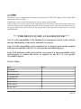
1
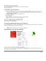
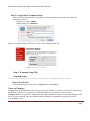
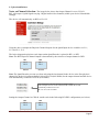
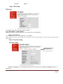
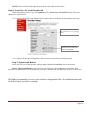
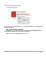
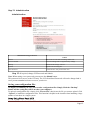
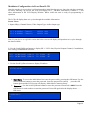
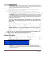
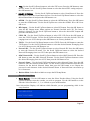
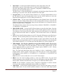
HD-4001 Quad Input DVB-T HD Encoder/Modulator User Guide and Install Manual Table of Contents Safety Precautions..........................................................................................................................................2 Package Contents ...........................................................................................................................................2 Product Description........................................................................................................................................3 Specification...................................................................................................................................................4 Installation......................................................................................................................................................5 Hardware Installations and Connections........................................................................................................5 Connecting to the GUI Interface:...................................................................................................................6 Encoder Programming and Setup via GUI Interface: ....................................................................................6 Overview Page of Zycast Encoder.................................................................................................................6 Common Setup...........................................................................................................................................7 RF Setup....................................................................................................................................................9 Encoder Setup ............................................................................................................................................9 Network Configuration ...........................................................................................................................11 Administration............................................................................................................................................12 Saving your configuration files....................................................................................................................12 Front Panel LCD Encoder Menu Map .........................................................................................................13 Modulator Configuration via Front Panel LCD ...........................................................................................14 Network Setup............................................................................................................................................18 ASI Output .................................................................................................................................................18 EAS ...........................................................................................................................................................19 HD-4001DM User Guide and Install Manual Page 1 Safety Precautions The presence of this symbol is to alert the installer and user to the presence of uninsulated dangerous voltages within the product’s enclosure that may be of sufficient magnitude to produce a risk of electric shock. TO REDUCE THE RISK OF FIRE OR ELECTRIC SHOCK, DO NOT EXPOSE THIS DEVICE TO RAIN OR MOISTURE. DO NOT OPEN THE UNIT. REFER SERVICING TO QUALIFIED PERSONNEL ONLY. DO NOT apply power to the unit until all connections have been made, all components have been installed and all wiring has been properly terminated. DO NOT terminate, change or uninstall any wiring without first disconnecting the unit’s power adapter from the device. This device is supplied with the appropriately rated power supply. The use of any other power supply could cause damage and invalidate the manufacturer’s warranty. DO NOT connect the power cord to the device if the power cord is damaged. DO NOT cut the power cord. DO NOT plug the power cord into an AC outlet until all cables and connections to the device have been properly connected. The device should be installed in an environment consistent with its operating temperature specifications. Placement next to heating devices and ducts is to be avoided as doing so may cause damage. The device should not be placed in areas of high humidity. DO NOT cover any of the device’s ventilation openings. DO NOT cover or obstruct the device’s fan or fan openings. If the device has been in a cold environment allow it to warm to room temperature for at least 2 hours before connecting to an AC outlet. Package Contents This package contains: One HD-4001DM Encoder / Modulator* One power cable One installation / configuration manual Inspect the package before starting installation to ensure there is no damage and all supplied contents are present. Contact your distributor or dealer should the device be damaged or package contents are incomplete. HD-4001DM User Guide and Install Manual Page 2 Product Description resi-linx digi-MOD HD Series Encoder/Modulators provides a DVB-T & ASI output stream - making it ideal for any Commercial RF Network. The high quality HD design allows for watching action packed movies and sports channels on any HDTV. The optional AC-3 Dolby Audio, EAS, and AES-128 Encryption capabilities rounds out the feature rich product series. The space saving design delivers up to 4 High Quality HD DVB-T channels in a single 1RU space. Front panel LCD Display for easy installation High Resolution 1080i/1080p LCN MODE Composite, Component, and HDMI (unencrypted) inputs MPEG2 or MPEG4(AVC) Video Output Selectable Constellation Closed Captioning Support 100dB Output Newly Added EAS Functionality* Rack mountable 1RU height Front Panel Rear Panel HD-4001DM User Guide and Install Manual Page 3 Specification VIDEO INPUTS (Video by Priority) HDMI 1.4v Component YprPb (RCA) Composite CVBS (RCA) AUDIO INPUTS Audio Inputs L/R (RCA) Video Encoder Mode MPEG-2, MPEG-4(AVC) Video Resolutions 1080p (AVC Only), 1080i, 720p, 576p, 576i, 480p, 480i AUDIO Encoder Audio Compression MPEG-1 Layer II, AAC, AC-3 (Optional), AC-3 Pass Through RF DVB-T Support Frequency Channel Plan - Varies by Country RF Channel Output 4 multiplexed on to 2 RF Output Constellation 64QAM (16QAM) Bandwidth 7 MHz RF Level Output 100dB MER >40dB Typical FEC 1/2, 2/3, 3/4, 5/6, 7/8 Guard Interval 1/4, 1/8, 1/16, 1/32 OFDM 8K (2K) Attenuation 1-20dB (1dB steps) RF Output "F" - Female 75 ohm Closed Captioning Control By Selection (use of CVBS Input) EAS Support Connection Terminal Type Video Input CVBS (RCA) Audio Input L/R (RCA) ASI Support Connection 75 ohm (BNC) Output TS Multiplexed IP Output - not available Management / Control Front Panel LCD Control Full Support (Up/Doen/OK Buttons) GUI IE9, Firefox, Chrome, Safari Password Protected Front Panel, GUI General Rack Mountable (1RU) 482.7mm x 240mm x 44.4mm - 19" EIA Standard Internal Fan Cooled Dual Internal LCD Front Panel Dual Line, Scrolling Display **Subject to change without noticifications HD-4001DM User Guide and Install Manual Page 4 Installation System Installer must adhere to Article 820-40 of the NEC that provides guidelines for proper grounding and specifies that the cable ground shall be connected to the grounding system of the building, as close to the point of cable entry as possible. Unpacking and Inspection Each unit is shipped factory tested. Ensure all items are removed from the container prior to discarding any packing material. Thoroughly inspect the unit for shipping damage with particular attention to connectors and controls. If there is any sign of damage to the unit or damaged or loose connectors contact your distributor immediately. Do not put the equipment into service if there is any indication of defect or damage. Hardware Installations and Connections It is highly recommended that quality cables and connectors be used for all video and audio source connections. 1. The unit is designed to be rack mounted in a standard EIA 19” rack. 2. The unit comes standard with HDMI, Component, and Composite video inputs. The HDT encoder / modulator are intelligently designed to detect the video input from the video source. HDMI Connection: Connect the HDMI cable(s) from the video source(s) into the HDMI input(s). If using a Component Video Cable, connect the Y (Green), Pb (Blue), and Pr (Red) video source cable to the unit’s Component input ports. If using a Composite Video source, use a 75Ω coaxial cable with RCA connectors to connect the video source (e.g., CATV, DVD, VCR, Camera) to the unit’s CVBS port (IN1…IN2, IN3, IN4 depending on your model). Repeat this step for each video source connection. 3. Component / Composite Audio inputs: Connect A/V audio input (Left / Right Audio) use RCA cables to connect the audio source to the red / white AUDIO L and AUDIO R INPUT jacks (IN1…IN2, IN3, IN4 depending on your model). Repeat this step for each audio source connection. Be sure the video and audio connections for each source are consistent with the unit’s inputs (IN1…IN2, IN3, IN4 depending on your model). 4. Use a quality 75Ω coaxial cable with “F” connectors from the unit’s RF OUT jack to the distribution system (combiner or reverse splitter) or directly to a television. 5. If your device is equipped with an IP output- connect the Ethernet cable to the IP output RJ45 connector. 6. If your device is equipped with an ASI output- connect the BNC cable to the ASI output. 7. If your device is EAS equipped make the proper connections (contact replay and Video /Audio Inputs) to the EAS device. 8. Connect the included power cord to the unit’s POWER plug. 9. Connect the power cord to an appropriately rated AC power outlet. HD-4001DM User Guide and Install Manual Page 5 DEVICE Programming and Setup To setup and program the Encoder you can use the GUI interface or the LCD Front Panel Connecting to the GUI Interface: 1.Connect an Ethernet cable directly (no Cross Over cable required) to the Web Management Port on the rear panel of the encoder or connect the Ethernet cable to an Ethernet switch. Connect an Ethernet Cable to your PC. 2.Using a Windows-based PC Select Windows Icon 3.Go to My Computer 4.Select Network 5.Allow UPnP to locate and list the device(s) in the right panel 6.Right Click and Select “View device Webpage”. Note: For Setup Using Front Panel LCD: Go to Page 15 in this manual. Encoder Programming and Setup via GUI Interface: After connecting the device to the “Web Management” port located on the rear of the device and locating the device via the 'Network' tool in 'My Computer' Step 1: Right Click and Select “View device Webpage”. Overview Page of resi-linx digi-MOD HD Overview status of the Encoder when fully functioning. Alternate between viewing status of RF Output 1 and RF Output 2 by selecting the RF Output section of the device you want to monitor. HD-4001DM User Guide and Install Manual Page 6 Note: Image displays the Quad version of the HDT Encoder. Step 2: Login Select Common Setup Once the Common Setup Tab is selected you will be prompted to enter the user name and password for device. Default User Name: admin Default Password: Admin123 Note: To change the Password for the GUI go to the Administration Tab Step 3: Common Setup Tab Common Setup Use the Common Setup Page to set the Output channel, Attenuation, LCN Mode, and Device Address. Step 4: Local Save Once all parameters are set you are required to do a Local Save. Notes on Changes: Changes made to an individual setup tab may require the installer to perform a Local Save AND Upload and Reboot to the device if you are only making changes to one parameter to the encoder. Example: Installer is required to change only the output channel for the device (No other changes to the device are not required). Once the channel has been changed, the installer is required to perform 1: Local Save and HD-4001DM User Guide and Install Manual Page 7 2: Upload and Reboot. Notes on Channel Selection: The image below shows the Output Channel is set to CH # 21. RF1 will output 1 QAM signal carrying 2 digital audio/video channels (within your device's Bandwidth settings). The device will automatically set RF2 to Ch # 22. Using the above example the Physical Channel Outputs for the Quad Input device would be set: 21.1, 21.2 and 22.1, 22.2. The below diagram depicts how each input on the Quad Encoder is placed in RF 1 or RF2. Note: The RF2 Physical Channel Output is determined by the selection of output channel of RF1. RF1 IN-1 IN-2 CH # 21 RF2 IN-3 IN-4 CH # 22 Note: The Quad Encoder prevents you from selecting the last channel in the device as the first physical channel for the device's output channel. Select CH # 68 (809.5MHz) for the output channel and the device will automatically set RF2 as CH # 69 (816.5MHz). Note: Channel 68 is the last channel accessible to select. In this example CH # 68 can be selected as RF1 and the device will automatically set RF2 as CH # 69. CH # 69 can not be set as RF1 Setting the Output Channel to CH# 68 would result in the following RF1/RF2 configuration (see below) RF1 IN-1 IN-2 RF2 IN-3 IN-4 HD-4001DM User Guide and Install Manual Page 8 CH # 68 CH # 69 Step 5: RF Setup RF Setup Use the RF Setup Page to setup each RF Output. Select RF Output 1 or RF Output 2. Select and set the required parameters you require for your installation. Step 6: Local Save Once all parameters are set you are required to do a Local Save. Note: The device shown is a QUAD input device. Your device will not show RF Output 2 if you are setting up a Single or Dual input encoder. Step 7: Encoder Setup Encoder Setup SelectEncoderforindividual Encoderprogramming Select the Encoder 1, 2, 3, 4 tab to program an individual encoder. Select and change all desired parameters. HD-4001DM User Guide and Install Manual Page 9 NOTE: There will be an Encoder tab present for each input on the device. Step 8: Local Save for each Encoder tab Once all parameters are set you are required to do a Local Save on EACH Encoder Tab where changes were performed. ***** Ensure all Encoder tab changes have been locally saved before performing the next step. Note: Local Save function will indicate the local changes made Upload and Reboot after all changes have been made and a Local Save performed ***** Ensure all Encoder changes have been locally saved before performing Step 9. Step 9: Upload and Reboot Once you have set all the encoder settings and performed a Local Save for each encoder Select “Upload and Reboot” after you have saved all your Local changes on each Tab. This function will upload and save all parameters set in the Common, RF, and Encoder sections of the device. We highly recommend you save your encoder configuration files. See Administration tab for how to back you device settings. HD-4001DM User Guide and Install Manual Page 10 Step 10: Network Configuration Tab Network Configuration Use the Network Setup Tab to configure the device’s IP address, Subnet Mask, Gateway, Enable/Disable DHCP, and set Host Name. Step 11: Save Network Configuration Save Config: Once all parameters are set you are required to select Save Config. This function will reboot and save the changes setting for the Network Configuration. Note: Only the Network Configuration changes will be saved. HD-4001DM User Guide and Install Manual Page 11 Step 12: Administration Administration Administration Page Functions Actions Reboot Reboot device. All unsaved settings will be lost. Reset to Default Reset all settings back to original factory settings Backup Download all settings of device Upload Upload a saved config file New Password Create and save new password for GUI Step 13: If required, change GUI Password and Submit. Note: When setting a new password you must use the Submit button. This password is for access to the GUI only. The LCD front Panel Password will not be changed and is set to prevent unauthorized users access to your device. Saving your configuration files We highly recommend you save your encoder configuration files. Simply Click the “Backup” button and the config files will be saved to your computer. To upload a configuration file- simply click “Choose File” then locate the file you want to upload. Click “Upload” to install the configuration files. This function is helpful to the installer when installing a large number of encoders in a single system. Setup Using Front Panel LCD HD-4001DM User Guide and Install Manual Page 12 Front Panel LCD Encoder Menu Map Common Setup Output Channel Attenuation LCN Mode Device Address Default Configuration Back to Main RF SETUP Select RF Constellation FEC Guard Interval OFDM RF Output Cell ID TS ID Network ID Org Network ID Network Name Back to Main ENCODER SETUP Encoder Setup Video Input Program Num Channel Name Provider Name LCN Aspect Ratio Video Output HDCP Audio Input Audio Output Closed Caption Brightness Contrast Saturation Hue Back to Main NETWORK SETUP Reset Network Back to Main EXIT HD-4001DM User Guide and Install Manual Page 13 Modulator Configuration via Front Panel LCD Once the encoder is powered up it will go through its initial booting process. Once the unit has completed its initial “Booting” up process the LCD will display IN-1..., Bit Rate information, Channel-1...., and other information in the LCD Display Window. When visible the unit is ready for programming or operation. The LCD will display data as it cycles through the available information. Screen Views: 1: Inputs, Mbps, Channel Names, Video Output Type, Audio Output type IN-1 8.231Mbps Channel-1 IN-2 8.435Mbps Channel-2 MPEG2 MP2 MPEG2 MP2 Note: If your device is a QUAD version the below screen will display all input data as is cycles through the data available. 2: Use the Scroll Up/Down button to display RF-1 / RF-2 data, Physical Output Channel, Constellation, FEC setting, OFDM Mode Selection. RF-1 21(480.5MHZ) QAM 64 RF-2 22(480.5MHZ) QAM 64 7/8 NORM 7/8 NORM 8K 8K 3: Use the Scroll Up/Down button to display IP address IP 172.1.252.10 Main Menu– To access the Main Menu first enter the password by pressing the OK button. Use the Scroll Up/Down buttons to enter the password. Once the password is entered press the OK button again and the LCD Screen will display “Main Menu Common Setup”. Password – Use the Scroll Up/Down buttons to enter the password. Password is 0000. Press the OK button for each number to enter the password. Press OK again after the display shows …... HD Series. PASSWORD=? 0 HD-4001DM User Guide and Install Manual Page 14 Common Setup Menu Output Channel – Use the Scroll Up/Down button to change the output channel. Use the Scroll Up/Down buttons to select the desired output channel. Once the desired output channel is selected press the OK button to set the channel. The LCD Display will show both the channel number and the frequency number of the output channel (example: 21 480.5000MHz) Note: The RF2 Channel Physical output is determined by the selection of output channel of RF1 The Quad Encoder prevents you from selecting the last channel in the device. **See page 9 of this manual for more information on this topic Attenuation – Use the Scroll Up/Down button to select Attenuation. Press the OK button to enter the Attenuation menu. Use the Scroll/Up down button to select the desired attenuation in 1dB increments from 0 to minus 20 dB. Once the desired attenuation level is found press the OK button to set. LCN – Use the Scroll Up/Down button to select LCN MODE. Press the OK button to enter the LCN menu. Menu options are APN, NORDIG, ITC, and EACEM. Factory default: APN. Use the Scroll Up/Down button to select the desired LCN and press the OK button to set. Device Address – Use the Scroll Up/Down button to select Device Address. Press the OK button to enter the Device Address menu. Use the Scroll Up/Down to select the Desired Address ranging from 1 to 255 then press OK to set. A unique device address is required if setting up more than 1 encoder per site. This allows the user to distinguish each device. Default Configuration –To reset the Encoder/Modulator back to the factory default select the Default Configuration Menu. Press OK to enter the Default Configuration Menu. Using the Up/Down button select YES to reset all programmed settings back to the factory default setting. Factory Default: NO. Caution: Once the “YES” button is pressed the unit will automatically reset to the factory default settings. All settings or changes to the encoder/modulator will be lost. Back to Main- Select Back to Main to escape the Common Setup Menu. RF Setup Menu Select RF- Press the OK button to enter the Select RF menu. Use the Scroll Up/Down button to Select the RF section of the Encoder. Select 1 or Select 2. The Single and Dual versions of this product will have Select 1 only. RF SETUP 1 SELECT RF Constellation – Use the Scroll Up/Down button to select Constellation. Press the OK button to enter the Constellation menu. Select the desired Constellation / QAM setting then press the OK button to set. HD-4001DM User Guide and Install Manual Page 15 FEC- Use the Scroll Up/Down button to select the FEC menu. Press the OK button to enter the FEC menu. Use the Scroll Up/Down button to select the desired FEC setting and press the OK button to set. GUARD INTERVAL – Use the Scroll Up/Down button to select Guard Interval. Press the OK button to enter the Guard Interval menu. Use the Scroll Up/Down button to select the desired Guard Interval and press the OK button to set. OFDM - Use the Scroll Up/Down button to select the OFDM menu. Press the OK button to enter the OFDM menu. Use the Scroll Up/Down to select the OFDM 2K or 8K. Press OK to set. RF Output – Use the Scroll Up/Down button to select RF Output. Press the OK button to enter the RF Output menu. Menu options are Normal, Inverted and C.W. The factory default is Normal. Use the Scroll Up/Down button to select the desired RF Output and press the OK button to set. CELL ID –Use the Scroll Up/Down button to select CELL ID. Press the OK button to enter the CELL ID menu. Use the Scroll Up/Down button to select the desired CELL ID ranging from 0 to 65535 then press the OK button to set. Factory default is 0. TS ID – Use the Scroll Up/Down button to select TS ID. Press the OK button to enter the TS ID menu. Use the Scroll Up/Down button to select the desired Stream ID ranging from 0 to 65535 then press the OK button to set. Network ID – Use the Scroll Up/Down button to select Network ID. Press the OK button to enter the Network ID menu. Use the Scroll Up/Down button to select the desired Network ID ranging from 0 to 65535 then press the OK button to set. ORG Network ID – Use the Scroll Up/Down button to select ORG Network ID. Press the OK button to enter the ORG Network ID menu. Use the Scroll Up/Down button to select the desired ID ranging from 0 to 65535 then press the OK button to set. Network Name – Use the Scroll Up/Down button to select Network Name. Press the OK button to enter the Network Name menu. Use the Scroll Up/Down buttonto select the first character for the desired Network Name then press the OK button to set. Repeat the process for each character in the desired Network Name. A Network Name can consist up to 16 characters. Back to Main- Select Back to Main to escape the RF Setup Menu. Encoder Setup Menu Select Encoder- Use the OK button to enter the Select Encoder Menu. Using the Scroll Up/Down buttons select the encoder you wish to program. Use the OK button to set the Encoder. Select Encoder 1, 2, 3, or 4 based on your model number. Once Selected the Display will indicate which Encoder you are programming while in the setup function ENCODER SETUP 1 SELECT ENCODER HD-4001DM User Guide and Install Manual Page 16 Video Input – Use the Scroll Up/Down button to select Video Input. Press the OK button to enter the Video Input menu. Use the Scroll Up/Down button to select the Video Input option: Auto, Composite, Component, or HDMI. Factory default: Auto. Press the OK button to set. The HDT series of Encoder/Modulators is designed with Intelligent Input Detection (IID) technology. If you select Auto, the unit will detect the video input. Program Num - Use the Scroll Up/Down button to set 1 Program Num(Number). Press the OK button to enter the Program Num menu. Use the Scroll Up/Down to select the Program Num ranging from 1 to 65535 then press OK to set. Channel Name – Use the Scroll Up/Down button to select Channel Name. Press the OK button to enter the Channel Name menu. Use the Scroll Up/Down menu to select the first character of the desired Channel Name then press the OK button to set. Repeat the process until the Channel Name is completed. The Channel Name can be 7 characters long. Factory Default: CHANNEL-1, CHANNEL2, CHANNEL-3, CHANNEL-4. PROVIDER NAME – Use the Scroll Up/Down button to select Provider Name. Press the OK button to enter the Provider Name menu. Use the Scroll Up/Down menu to select the first character of the desired Provider Name then press the OK button to set. Repeat the process until the Provider Name is completed.. The Provider Name can be 16 characters long. LCN-Use the Scroll Up/Down button to set LCN. Press the OK button to enter The Source ID menu. Use the Scroll Up/Down to set the Source ID. Range: 1 to 999. Press OK to set. Aspect Ratio – Use the Scroll Up/Down button to select Aspect Ratio. Press the OK button to enter the Aspect Ratio menu. Use the Scroll Up/Down button to select the desired Aspect Ratio option of 4:3 or 16:9 then press the OK button to set. Factory default: 4:3. Video Output – This Encoder / Modulators may be Dual MODE Capable. The user may select to output video in either MPEG2 or AVC (MPEG4). Use the Scroll Up/Down button to select 1 Video Output. Press the OK button to enter the Video Output menu. Use the Scroll Up/Down button to select the Video Output option: MPEG2 or AVC. Factory default: MPEG2. Press the OK button to set. Note: The Dual and Quad Input allows the installer to select a combination of Video Output formats. Some versions of this device will allow the user to have both outputs broadcasting in either MPEG2 or AVC(MPEG4) or a combination of both MPEG2 and AVC(MPEG4). Note: The AVC version of this device is set to AVC Video Output. HDCP- Use the Scroll Up/Down button to select the HDCP menu- Use the Scroll Up/Down button to select the HDCP menu. Press the OK button to enter the HDCP menu. Select Enable / Disable. Each Encoder will require you to Enable the HDCP option. NOTE: It is the installers / property owner / integrator's responsibity to contract with the service provider regrding content authoization and the use of HDCP. Audio Input – Use the Scroll Up/Down button to select. Press the OK button to enter the Audio Input menu. Use the Scroll Up/Down button to select the Audio Input option: HD-4001DM User Guide and Install Manual Page 17 Analog. Factory Set: Analog. Audio Output – Use the Scroll Up/Down button to select Audio Output. Press the OK button to enter the Audio Output menu. Use the Scroll Up/Down button to select the Audio Output option: MP2 (MPEG2 Layer I Audio), AAC, or AC3. Factory default: MP2. Press the OK button to set. Some versions of the HDT Encoder will not allow you to select AC3 as an option. Contact your Distributor if you require an AC3 version of this device. Closed Caption- Use the Scroll Up/Down button to select the Closed Caption Menu. Press the OK button to enter the Closed Caption menu. Enable / Disable Closed Caption control. Each Encoder will require you to Enable the Closed Caption option if you require Closed Captioning Support on a particular video output. NOTE: WHEN USING CLOSED CAPTIONING- USER MUST CONNECT FROM THE CONTENT SOURCE THE COMPOSITE OUTPUT OR CC OUTPUT SOURCE TO THE ENCODER'S CVBS INPUT CONNECTOR. Brightness – Use the Scroll Up/Down button to select Brightness. Press the OK button to enter the Brightness menu. Use the Scroll Up/Down button to select the desired Brightness value (0 to 255) and press the OK button to set. Factory default: 128. Contrast – Use the Scroll Up/Down button to select Contrast. Press the OK button to enter the Contrast menu. Use the Scroll Up/Down button to select the desired Contrast value (0 to 255) and press the OK button to set. Factory default: 128. Saturation – Use the Scroll Up/Down button to select Saturation. Press the OK button to enter the Saturation menu. Use the Scroll Up/Down button to select the desired Saturation value (0 to 255) and press the OK button to set. Factory default: 128. Hue – Use the Scroll Up/Down button to select Hue. Press the OK button to enter the Hue menu. Use the Scroll Up/Down button to select the desired Hue value (0 to 255) and press the OK button to set. Factory default: 128. Back to Main- Select Back to Main to escape the Encoder Setup Menu. Network Setup Reset Network- Select Reset Network from the Network Setup to Reset the Network settings. Back to Main- Select Back to Main to escape the Encoder Setup Menu. ASI OutPut This device may come equipped with an ASI combined output. Connect a BNC cable to the ASI output connector (75 Ω ) and to your Broadcast capable device. HD-4001DM User Guide and Install Manual Page 18 EAS This device may be equipped EAS Terminals/connections and CVBS (Video Input) and L/R audio input connections on the rear panel. If applicable, connect your EAS Alert Device System outputs to the Encoder. If the encoder receives the proper Event signal from your EAS device, the normal input audio/video would be replaced by the audio and video from the EAS system device. Once the encoder has received the proper signal from your EAS device the normal input video and audio would return to a normal operating mode. ****THIS DEVICE IS NOT AN EAS RECEIVER**** Note: It is the responsibility of the Installer/User to properly connect, verify, and test the EAS functionality of this device with the EAS receiver. Note: It is the responsibility of the Installer/User to properly perform the required EAS tests as required by the FCC or your specific Government Agency. If the EAS functions on this device fail for any reason it is the responsibility of the user/integrator to replace this device as required by the FCC or your specific Government Agency. Product Notes: Item Value Password Serial Number Installation Date Purchase Date Video Input 1 Video Input 2 Video Input 3 Video Input 4 HD-4001DM User Guide and Install Manual Page 19 HD-4001DM User Guide and Install Manual Page 20