1
Pololu Wixel User's Guide
© 2001–2010 Pololu Corporation
Pololu Wixel User's Guide
Page 1 of 49
Pololu Wixel User's Guide
© 2001–2010 Pololu Corporation
1. Overview . . . . . . . . . . . . . . . . . . . . . . . . . . . . . . . . . . . . .
1.a. Module Pinout and Components . . . . . . . . . . . . . . . . . . . . .
1.b. Supported Operating Systems . . . . . . . . . . . . . . . . . . . . . . .
1.c. Government Regulations for Radio Devices . . . . . . . . . . . . . . .
2. Contacting Pololu . . . . . . . . . . . . . . . . . . . . . . . . . . . . . . . . .
3. Getting Started . . . . . . . . . . . . . . . . . . . . . . . . . . . . . . . . . .
3.a. Installing Windows Drivers and Software . . . . . . . . . . . . . . . .
3.b. Installing Linux Drivers and Software . . . . . . . . . . . . . . . . . .
3.c. Installing Mac OS Drivers and Software . . . . . . . . . . . . . . . . .
3.d. Loading an Example App . . . . . . . . . . . . . . . . . . . . . . . . .
4. Configuring Your Wixels . . . . . . . . . . . . . . . . . . . . . . . . . . . .
5. Connecting Your Wixels . . . . . . . . . . . . . . . . . . . . . . . . . . . . .
5.a. Connecting Power . . . . . . . . . . . . . . . . . . . . . . . . . . . . .
5.b. Connecting a Microcontroller via TTL Serial . . . . . . . . . . . . . .
5.c. Connecting Buttons and Starting the Bootloader . . . . . . . . . . . . .
6. Using a Virtual COM Port . . . . . . . . . . . . . . . . . . . . . . . . . . . .
6.a. Determining the Port Name . . . . . . . . . . . . . . . . . . . . . . . .
6.b. Using a Terminal Program . . . . . . . . . . . . . . . . . . . . . . . .
6.c. Writing PC Software to Use a Serial Port . . . . . . . . . . . . . . . . .
7. Ensuring a Good Radio Signal . . . . . . . . . . . . . . . . . . . . . . . . . .
8. Schematic Diagram . . . . . . . . . . . . . . . . . . . . . . . . . . . . . . . .
9. Wixel Apps . . . . . . . . . . . . . . . . . . . . . . . . . . . . . . . . . . . .
9.a. Example App: Blink LED . . . . . . . . . . . . . . . . . . . . . . . . .
9.b. Wireless Serial App . . . . . . . . . . . . . . . . . . . . . . . . . . . .
9.c. USB-to-Serial App . . . . . . . . . . . . . . . . . . . . . . . . . . . .
9.d. I/O Repeater App . . . . . . . . . . . . . . . . . . . . . . . . . . . . .
9.e. ShiftBrite App . . . . . . . . . . . . . . . . . . . . . . . . . . . . . . .
9.f. Wireless Tilt Mouse App . . . . . . . . . . . . . . . . . . . . . . . . .
10. Writing Your Own Wixel App . . . . . . . . . . . . . . . . . . . . . . . . .
10.a. Getting Started in Windows . . . . . . . . . . . . . . . . . . . . . . .
10.b. Compiling an Example App . . . . . . . . . . . . . . . . . . . . . . .
10.c. Using the Eclipse IDE . . . . . . . . . . . . . . . . . . . . . . . . . .
10.d. Sharing Your App with the Wixel Community . . . . . . . . . . . . .
10.e. USB Configurations Recognized by the Wixel Configuration Software
10.f. Wixel App File Format . . . . . . . . . . . . . . . . . . . . . . . . . .
.
.
.
.
.
.
.
.
.
.
.
.
.
.
.
.
.
.
.
.
.
.
.
.
.
.
.
.
.
.
.
.
.
.
.
.
.
.
.
.
.
.
.
.
.
.
.
.
.
.
.
.
.
.
.
.
.
.
.
.
.
.
.
.
.
.
.
.
.
.
.
.
.
.
.
.
.
.
.
.
.
.
.
.
.
.
.
.
.
.
.
.
.
.
.
.
.
.
.
.
.
.
.
.
.
.
.
.
.
.
.
.
.
.
.
.
.
.
.
.
.
.
.
.
.
.
.
.
.
.
.
.
.
.
.
.
.
.
.
.
.
.
.
.
.
.
.
.
.
.
.
.
.
.
.
.
.
.
.
.
.
.
.
.
.
.
.
.
.
.
.
.
.
.
.
.
.
.
.
.
.
.
.
.
.
.
.
.
.
.
.
.
.
.
.
.
.
.
.
.
.
.
.
.
.
.
.
.
.
.
.
.
.
.
.
.
.
.
.
.
.
.
.
.
.
.
.
.
.
.
.
.
.
.
.
.
.
.
.
.
.
.
.
.
.
.
.
.
.
.
.
.
.
.
.
.
.
.
.
.
.
.
.
.
.
.
.
.
.
.
.
.
.
.
.
.
.
.
.
.
.
.
.
.
.
.
.
.
.
.
.
.
.
.
.
.
.
.
.
.
.
.
.
.
.
.
.
.
.
.
.
.
.
.
.
.
.
.
.
.
.
.
.
.
.
.
.
.
.
.
.
.
.
.
.
.
.
.
.
.
.
.
.
.
.
.
.
.
.
.
.
.
.
.
.
.
.
.
.
.
.
.
.
.
.
.
.
.
.
.
.
.
.
.
.
.
.
.
.
.
.
.
.
.
.
.
.
.
.
.
.
.
.
.
.
.
.
.
.
.
.
.
.
.
.
.
.
.
.
.
.
.
.
.
.
.
.
.
.
.
.
.
.
.
.
.
.
.
.
.
.
.
.
.
.
.
.
.
.
.
.
.
.
.
.
.
.
.
.
.
.
.
.
.
.
.
.
.
.
.
.
.
.
.
.
.
.
.
.
.
.
.
.
.
.
.
.
.
.
.
.
.
.
.
.
.
.
.
.
.
.
.
.
.
.
.
.
.
.
.
.
.
.
.
.
.
.
.
.
.
.
.
.
.
.
.
.
.
.
.
.
.
.
.
.
3
4
7
7
8
9
9
13
13
13
17
20
20
21
22
25
25
25
26
27
28
29
29
29
33
34
36
38
41
41
41
43
46
48
48
Page 2 of 49
Pololu Wixel User's Guide
© 2001–2010 Pololu Corporation
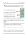
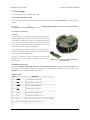
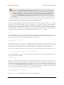
1. Overview
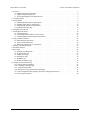
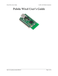
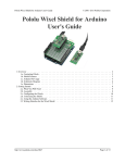
The Pololu Wixel is a general-purpose programmable module featuring a
2.4 GHz radio and USB. The Wixel is based around the
CC2511F32 [http://focus.ti.com/docs/prod/folders/print/cc2511f32.html]
microcontroller from Texas Instruments, which has an integrated radio
transceiver, 32 KB of flash memory, 4 KB of RAM, and a full-speed USB
interface. A total of 15 general-purpose I/O lines are available, including
6 analog inputs, and the 0.1" pin spacing makes the Wixel easy to use
with breadboards [http://www.pololu.com/catalog/category/28] and perfboards.
We provide free, open-source apps for the Wixel that you can load and
configure with its built-in USB bootloader, turning it into whatever you
need for your current project. Simply download a different app to reuse
the Wixel in your next project.
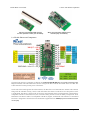
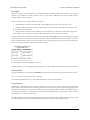
Our Wireless Serial app turns a pair of Wixels into a wireless USB/TTL
serial link for communication between two microcontrollers or between a
PC and a microcontroller. This can be used, for example, for
communication between two robots or to remotely monitor a robot from a
computer. Using an RF bit rate of 350 kbps, the serial app is capable of
transmitting or receiving up to 10 KB of data per second and can reach a
range of approximately 40 feet (under typical conditions indoors).
Multiple serial links can be used simultaneously on different channels.
Detailed information about the wireless serial app is available in Section
9.b.
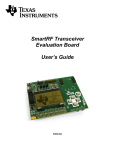
Wixel programmable USB
wireless module.
Wixel programmable USB
wireless module enabling
wireless communication
between a PC and robot.
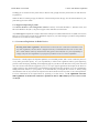
Our USB-to-Serial app turns a single Wixel into a USB-to-TTL serial
adapter that is capable of baud rates as high as 350,000 bps and supports four serial control signals. This app does
not use the radio. Detailed information about this app is available in Section 9.c.
Our I/O Repeater app allows you to wirelessly extend the reach of your microcontroller’s I/O lines up to 40 feet
using two or more Wixels. Detailed information about this app is available in Section 9.d.
We plan to release additional apps in the future for wireless AVR programming, wireless sensing, and more.
You can also write your own apps using the open-source Wixel SDK (see Section 10) and share them with the
community.
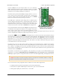
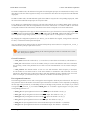
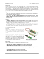
Included Hardware
The Wixel is available in two versions:
The Partial Kit version [http://www.pololu.com/catalog/product/1337] comes with a 25×1 straight 0.1" male header
strip [http://www.pololu.com/catalog/product/965]. This version is ideal for compact installations and allows flexibility
in choice of connectors.
The Assembled version [http://www.pololu.com/catalog/product/1336] comes with its header pins soldered in, so it is
ready to be connected to your project with no soldering required.
1. Overview
Page 3 of 49
Pololu Wixel User's Guide
Wixel programmable USB wireless
module (without header pins installed).
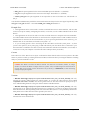
© 2001–2010 Pololu Corporation
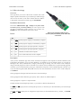
Wixel programmable USB wireless
module (fully assembled).
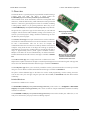
1.a. Module Pinout and Components
The Wixel can connect to a computer’s USB port via a USB A to mini-B cable [http://www.pololu.com/catalog/product/
130] (not included). The USB connection is used to configure the Wixel and also to transmit and receive data. The
USB connection can also provide power to the Wixel.
On the side of the board opposite the USB connector, the Wixel has a 2.4 GHz PCB trace antenna. This antenna,
along with the other RF circuitry, forms a radio that allows the Wixel to send and receive data packets in the
2.4 GHz band. The Wixel is based on the CC2511F32 microcontroller from Texas Instruments, which makes it
compatible with the CC2500 transceiver, the CC2510Fx family, and the CC2511Fx family of chips from Texas
Instruments. The Wixel’s radio is not compatible with Wi-Fi, Zigbee, or Bluetooth. The antenna is a “meandered
Inverted F” design that is described in Texas Instrument’s application note AN043 [http://focus.ti.com/lit/an/swra117d/
swra117d.pdf].
1. Overview
Page 4 of 49
Pololu Wixel User's Guide
© 2001–2010 Pololu Corporation
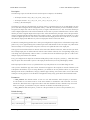
The three GND pins are all connected and are at 0 V by definition.
When connecting the Wixel to other electronic systems, you should
make sure that the Wixel’s GND is connected to the other system’s
GND unless you are doing something very advanced.
The Wixel can be powered from VIN pin. Simply connect a 2.7–6.5 V
power source between VIN and GND, with the positive terminal going
to VIN. It is OK to connect VIN and USB at the same time. See Section
5.a for more information about powering your Wixels.
The VALT pin is connected to three things: the 5V USB bus power
from the USB port (through a diode), VIN (through a diode), and to the
input of the Wixel’s on-board 3.3 V regulator. The connection to 5V is
switched off when a power supply is connected to VIN. Most people
will not need to use the VALT pin: see Section 5.a for example uses.
Wixel programmable USB wireless
module, bottom view with US
The pin labeled 3V3 on the board (3.3V Output in the diagram above)
quarter for size reference.
is connected to the output of the Wixel’s 3.3V regulator. This power
source can be used to power other low-current peripherals in your
system. With an input voltage of 5 V (either from USB, VIN, or VALT), this output can provide up to 150 mA of
current. At higher input voltages, this output can provide up to 100 mA.
The pin labeled RST on the board (RESET in the diagram above) is the reset line of the microcontroller. This pin
can be driven low to perform a hard reset of the Wixel’s microcontroller. This should not be necessary for typical
users, but it can be useful while you are developing a Wixel application (see Section 5.c). This pin is internally
pulled high to 3.3 V, so it is okay to leave it unconnected. If you do wire something to this pin, the CC2511F32
datasheet recommends adding an external RC filter with values of 1 nF and 2.7 kΩ close to the pin in order to
avoid unintended reset of the microcontroller.
The Wixel has 15 free I/O lines whose behavior depends on the application that is loaded onto the Wixel.
Specifically, these are all of the pins on Port 0 (P0_0 through P0_5), all of the pins on Port 1 (P1_0 through
P1_7), and P2_1. The P2_1 pin is tied to the red LED but the other 14 free I/O lines are only connected to the
microcontroller. The P2_2 line is also accessible, but it is tied to the yellow LED and is used to get the Wixel into
bootloader mode (see Section 5.c).
The amount of current that can be supplied by the CC2511F32’s I/O pins is not well-documented by the
manufacturer. According to this forum post by a TI Employee [http://e2e.ti.com/support/low_power_rf/f/155/p/31555/
319919.aspx], regular I/O pins are designed to be able to source 4 mA while P1_0 and P1_1 are designed for 20 mA.
Caution: The Wixel’s I/O lines are not 5V tolerant. You must use level-shifters, diodes, or voltage
dividers to connect the Wixel to outputs from 5V systems.
The CC2511F32 has several peripherals that are available to be used in Wixel applications:
• 2 USARTs which can perform asynchronous serial or SPI communication
• 3 timers that are capable of PWM output as shown above, plus 1 more internal timer
• 6 analog input-capable pins, connected to a 7–12 bit ADC
1. Overview
Page 5 of 49
Pololu Wixel User's Guide
© 2001–2010 Pololu Corporation
Different Wixel applications may use different sets of these peripherals. Consult the application documentation
for details on the behavior of the I/O lines.
The pinout and peripheral diagram at the top of this section is also available as a printable
pdf [http://www.pololu.com/file/download/wixel_pinout.pdf?file_id=0J462] (145k pdf).
The Wixel has three indicator LEDs:
Green USB LED
The green LED is powered from USB, so it can only be turned
on when USB cable is connected and supplying power to the
Wixel.
While the Wixel is in bootloader mode (i.e. the app is stopped),
this LED is used to indicate the USB status of the device. When
the Wixel USB Bootloader connects to USB, the green LED
starts blinking slowly. The blinking continues until the
bootloader receives a particular message from the computer
indicating that the Wixel USB Bootloader drivers are installed
correctly (see Section 3.a for driver installation instructions).
After the bootloader gets this message, the green LED will do a
double-blinking pattern. The green LED also turns off during
USB Suspend Mode, which happens when the computer goes to
sleep or shuts down the USB port for any other reason.
Wixel indicator LEDs.
While the Wixel is running its app, the behavior of the LED depends on the app. The standard apps provided
by Pololu all behave as follows: When the app connects to USB, the green LED starts blinking slowly. The
blinking continues until the app receives a particular message from the computer indicating that the app’s drivers
are installed correctly. After the app gets this message, the green LED turns solidly on. The green LED also turns
off during USB Suspend Mode, which happens when the computer goes to sleep or shuts down the USB port for
any other reason.
Red LED
While the Wixel is in bootloader mode (i.e. the app is stopped), this LED indicates whether there is an application
on the Wixel. If there is no application, the red LED will be on. Otherwise, it will be off. By default, the Wixel
does not have an application on it, so this LED will be on the first time you power your Wixel.
The P2_1 pin is connected to the red LED, so this line will go high when the red LED is on and otherwise be
pulled low.
While the Wixel is running its app, the behavior of this LED depends on the app. See the documentation of your
particular app for more details.
Yellow LED
While the Wixel is in bootloader mode (i.e. the app is stopped), this LED turns solidly on and flickers whenever
the bootloader receives a command from Wixel software on the computer. The Wixel Configuration Utility
queries the state of the bootloader once per second, so if the Wixel Configuration Utility is open then the LED
will flicker once per second. While the Wixel is being programmed, the yellow LED will constantly flicker.
1. Overview
Page 6 of 49
Pololu Wixel User's Guide
© 2001–2010 Pololu Corporation
The P2_2 pin is connected to the yellow LED, so this line will go high when the yellow LED is on and otherwise
be pulled low.
While the Wixel is running its app, the behavior of this LED depends on the app. See the documentation of your
particular app for more details.
1.b. Supported Operating Systems
The Wixel USB drivers and configuration software currently work under Windows 7, Windows Vista, and
Microsoft Windows XP (SP 3). We plan to support Linux and Mac OS in the future.
Any Wixel app that implements a single USB virtual COM port or a Human Interface Device (HID) will work in
Mac OS or Linux with no special driver installation required, so you could configure your Wixel using Windows
but then use it on a Mac or Linux computer.
1.c. Government Regulations for Radio Devices
Warning about radio regulations: The Wixel has not been tested or certified for conformance with
any radio regulations, and the Wixel is shipped with only a bootloader that does not use the radio.
The 2.4 GHz band is relatively unrestricted in many parts of the world, but it is your responsibility to
comply with your local regulations if you program your Wixel to use its wireless capabilities.
The Wixel is a multi-purpose development platform, not a finished product, and it is not certified by the FCC
or any other government agency. It is your responsibility to follow local regulations and use good engineering
practices when developing, installing, and configuring apps for your Wixel. The Wixel has a low-power radio and
uses the reference PCB antenna suggested by TI, so we expect typical applications developed for the Wixel to
comply with FCC rules, but the Wixel is not intended for integration into other products. If you are contemplating
adding Wixel-like features to your product, we recommend that you integrate the CC2511 IC directly using
documentation from TI; any software developed for the Wixel should work on any other CC2511-based platform.
For more information on the requirements for operating a 2.4 GHz device, see TI Application Note 032:
SRD regulations for license-free transceiver operation in the 2.4 GHz band [http://focus.ti.com/lit/an/swra060/
swra060.pdf].
1. Overview
Page 7 of 49
Pololu Wixel User's Guide
© 2001–2010 Pololu Corporation
2. Contacting Pololu
We would be delighted to hear from you about any of your projects and
about your experience with the Wixel. You can contact
us [http://www.pololu.com/contact]
directly
or
post
on
our
forum [http://forum.pololu.com/]. Tell us what we did well, what we could
improve, what you would like to see in the future, or anything else you
would like to say!
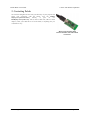
Wixel programmable USB
wireless module with USB cabled
connected.
2. Contacting Pololu
Page 8 of 49
Pololu Wixel User's Guide
© 2001–2010 Pololu Corporation
3. Getting Started
3.a. Installing Windows Drivers and Software
Before you connect a Wixel to a computer running Microsoft Windows, you should install the drivers:
1. Download
the
Wixel
Windows Drivers
(12007k zip)
and
Software [http://www.pololu.com/file/download/
wixel_windows_110322.zip?file_id=0J448]
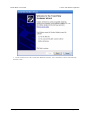
2. Open the ZIP archive and run setup.exe. The installer will guide you through the steps required to install
the Wixel Configuration Utility, the Wixel command-line utility (WixelCmd), and the Wixel drivers on your
computer. If the installer fails when run directly from the ZIP file, extract the contents of the ZIP file to a
temporary directory on your computer, right click setup.exe, and select “Run as Administrator”.
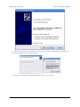
3. During the installation, Windows will warn you that the drivers have not been tested by Microsoft and
recommend that you stop the installation. Click “Continue Anyway” (Windows XP) or “Install this driver
software anyway” (Windows 7 and Vista).
4. After the installation is finished, your start menu should have a shortcut to the Wixel Configuration Utility
(in the Pololu folder). This is a Windows application that allows you to load apps onto your Wixel. There
will also be a command-line utility called WixelCmd which you can run at a Command Prompt.
Windows 7 and Windows Vista users: Your computer should now automatically install the necessary drivers
when you connect a Wixel. No further action from you is required.
Windows XP users: Follow steps 5–9 for each new Wixel you connect to your computer. You will also have to
follow these steps again the first time you run an actual Wixel app on the Wixel.
5. Connect the device to your computer’s USB port.
6. When the “Found New Hardware Wizard” is displayed, select “No, not this time” and click “Next”.
3. Getting Started
Page 9 of 49
Pololu Wixel User's Guide
© 2001–2010 Pololu Corporation
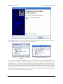
7. On the second screen of the “Found New Hardware Wizard”, select “Install the software automatically”
and click “Next”.
3. Getting Started
Page 10 of 49
Pololu Wixel User's Guide
© 2001–2010 Pololu Corporation
8. Windows XP will warn you again that the driver has not been tested by Microsoft and recommend that
you stop the installation. Click “Continue Anyway”.
9. When you have finished the “Found New Hardware Wizard”, click “Finish”.
3. Getting Started
Page 11 of 49
Pololu Wixel User's Guide
© 2001–2010 Pololu Corporation
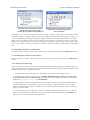
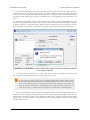
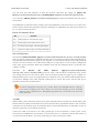
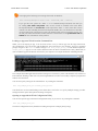
After installing the drivers, if you go to your computer’s Device Manager and expand the “Pololu USB Devices”
list, you should see an entry for the Pololu Wixel USB Bootloader.
Windows Vista or Windows 7 Device
Manager showing a Wixel in bootloader
mode.
Windows XP Device Manager showing a
Wixel in bootloader mode.
If you see the “Pololu Wixel USB Bootloader” entry in your device manager, it means that your Wixel is in
bootloader mode. Your Wixel should go into bootloader mode when you first plug it into USB, because there is no
app on the Wixel by default. Once you have loaded an app onto the Wixel using the Wixel Configuration Utility,
and the app is running, then you will not see the Pololu Wixel USB Bootloader entry in your Device Manager.
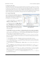
The entry you see in the Device Manager will depend on the application that is loaded on the Wixel. Some apps
might not enable the USB interface, in which case you will see no entry for the Wixel in the Device Manager.
However, typical Wixel Apps will appear in your Device Manager as a single Virtual COM port (with product ID
0x2200) in the “Ports (COM & LPT)” list as shown below:
3. Getting Started
Page 12 of 49
Pololu Wixel User's Guide
Windows Vista or Windows 7 Device
Manager showing a Wixel that is
running an app with a virtual COM port.
© 2001–2010 Pololu Corporation
Windows XP Device Manager showing a
Wixel that is running an app with a
virtual COM port.
In parentheses, you will see the name of the port (for example, COM5 or COM6). Some software will not allow
connection to higher COM port numbers. If you need to change the COM port number assigned to a Wixel, you
can do so using the Device Manager. Bring up the properties dialog for the COM port and click the “Advanced…”
button in the “Port Settings” tab. From this dialog you can change the COM port assigned to your device.
Windows will remember which COM port was assigned to which Wixel using the built-in serial number of the
Wixel; a given Wixel will always get assigned to the same COM port regardless of which USB port it is plugged
into.
3.b. Installing Linux Drivers and Software
The Wixel software currently does not work on Linux, but certain Wixel apps should. See Section 1.b for details.
3.c. Installing Mac OS Drivers and Software
The Wixel software currently does not work on Mac OS, but certain Wixel apps should. See Section 1.b for
details.
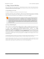
3.d. Loading an Example App
When you first get your Wixel it will have no application loaded. To make your Wixel do something useful, you
must load an app onto it. This section guides you through the steps needed to load an example application onto
the Wixel using the Wixel Configuration Utility.
1. Install the Wixel drivers and software by following the instructions in the preceding sections.
2. Download the example application here: Example Blink LED App v1.0 [http://www.pololu.com/file/
download/example_blink_led_v1.0.wxl?file_id=0J449] (11k wxl). If you want to see the source code, it is in the Wixel
SDK under apps/example_blink_led. (See Section 10.a.)
3. Open the app in the Wixel Configuration Utility. To do this in Windows, you can simply double-click on
the Wixel App (WXL) file. Alternatively, you can open the Wixel Configuration Utility, click the “Open…”
button, and select the Wixel App file. In Windows, you can find the Wixel Configuration Utility in the Pololu
folder in your Start Menu.
4. Connect a Wixel to your computer via USB. You should see it appear in the “Wixels” list. If it does not
appear, you might need to use a button or wire to get your Wixel into bootloader mode (see Section 5.c). At
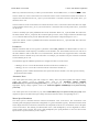
this point, your screen should look something like this:
3. Getting Started
Page 13 of 49
Pololu Wixel User's Guide
© 2001–2010 Pololu Corporation
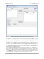
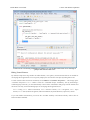
The Wixel Configuration Utility with the Example Blink LED App open.
5. Note that in the Wixels box, there is a list of all the Wixels connected to USB that the Wixel
Configuration Utility can recognize. There is one Wixel connected, and its 32-bit serial number is displayed
in the list. Also note that in the App Configuration box, we have opened the example_blink_led_v1.0.wxl
app. This app has one parameter, blink_period_ms, and it is currently set to 500 (the default).
6. Select the Wixel by left-clicking on its entry in the Wixels list. If you see a dialog box pop up, this
is because the Wixel already has an application on it and the Auto Read checkbox is checked. Click the
“Cancel” button in that dialog because we are not interested in reading the contents of the Wixel yet.
7. Click the Write to Wixel button. This writes the currently open app and the settings to the selected
Wixel, and then starts running the application.
8. The example blink LED application should be running now. The Wixel’s yellow LED should be off,
and the red LED should be blinking. If you are in Windows XP and this is the first time you have run an
application on this Wixel, the Found New Hardware Wizard will pop up and you will have to follow steps
5–9 from Section 3.a to install the drivers properly. After the USB drivers are installed properly, the green
LED should be on solid. Congratulations, you have successfully configured your Wixel!
3. Getting Started
Page 14 of 49
Pololu Wixel User's Guide
© 2001–2010 Pololu Corporation
9. The speed of the blinking is determined by the blink_period_ms parameter. The units of this parameter
are milliseconds (ms). Try changing blink_period_ms to 100 by double-clicking on the number and typing
“100”. You can now write the new configuration to the Wixel by clicking the “Write to Wixel” button. After
the writing is done and the app is running, you should see the red LED blinking 5 times faster than it was
before.
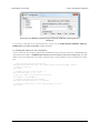
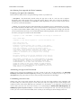
10. The Wixel Configuration Utility can also read the settings from the Wixel. To demonstrate this, close
the Wixel Configuration Utility, reopen it, and select your Wixel. Since the Auto Read checkbox is checked
by default, and there is an application on the Wixel, the Wixel Configuration Utility will attempt to read the
Wixel’s settings. If you have not yet opened the correct app, a dialog box like the one below will pop up:
If Auto Read is enabled when you select a Wixel with an app on it, then you might be prompted
you to open the App File.
11. To read the settings from a Wixel, you will need to open the app that is currently on the Wixel. Click
the “Open” button in the dialog, and select example_blink_led_v1.0.wxl.
It is necessary to open the app file that you originally loaded onto the Wixel because the file
contains metadata required to interpret the settings contained in the Wixel’s flash memory.
If you open a different app file, even a different version of the same app, your settings will
likely be corrupted. In this case, a warning dialog box will pop up to warn you and give you
some options. Since you still have the correct app file, you should not see that dialog now.
12. After you open the Wixel App file, the Wixel Configuration Utility will read the Wixel and compare its
contents to what is in the app. You will then see the Wixel’s settings displayed on the right: blink_period_ms
should be 100. Note that the number 100 is displayed in bold. This is because it differs from the default
setting, which is 500. You can reset it to the default at any time by right-clicking on the number and selecting
“Reset to Default Value”.
3. Getting Started
Page 15 of 49
Pololu Wixel User's Guide
© 2001–2010 Pololu Corporation
After completing this tutorial you should be comfortable with writing apps to the Wixel and reading back the
settings. This is all you need to know in order to configure your Wixels. When you load a real application, such
as the Wireless Serial App [http://www.pololu.com/docs/0J46/9.b], the only thing that will be different are the names
and meanings of the parameters. To understand what the different parameters mean, refer to the documentation
for your specific app.
Some apps might implement a non-standard USB interface (or no USB interface at all). In that case, they will
not be recognized by the Wixel Configuration Utility while the app is running, so you will need to get them into
bootloader mode manually (see Section 5.c and also the app’s documentation).
3. Getting Started
Page 16 of 49
Pololu Wixel User's Guide
© 2001–2010 Pololu Corporation
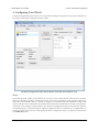
4. Configuring Your Wixels
The Wixel Configuration Utility allows you to write and read settings from the Wixel. This section explains all of
the features of the Wixel Configuration Utility in detail.
The Wixel Configuration Utility with 2 Wixels connected and an App file open.
Wixels
On the left side of the window, in the Wixels box, you can see a list of all the Wixels connected to the computer
that are recognized by the Wixel Configuration Utility. The Wixel Configuration Utility should recognize any
Wixel that is in bootloader mode (i.e. the app is stopped) or is running an app that implements a single USB
Virtual COM port with a USB Vendor ID of 0x1FFB (for Pololu) and a Product ID of 0x2200. If your Wixel is
connected to your computer, but does not show up in the Wixel Configuration Utility, then your drivers might not
be installed properly, or the Wixel might be running an application that uses a different type of USB interface or
doesn’t use USB at all. If you have trouble getting the Wixel Configuration Utility to recognize your Wixel, then
see Section 10 for help.
4. Configuring Your Wixels
Page 17 of 49
Pololu Wixel User's Guide
© 2001–2010 Pololu Corporation
The text displayed in the Wixel list (e.g. “07-C2-C8-3A”) is the serial number of your Wixel. Each Wixel has a
unique 32-bit serial number which was randomly generated and assigned to it when the Wixel was manufactured.
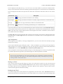
The icon displayed in the Wixel list represents the current state of the Wixel. Each Wixel will be in one of these
states:
Wixel Status Icon
Description
App Running
The app you loaded on the Wixel is now running.
App Stopped
The app you loaded on the Wixel is currently stopped; the Wixel is in bootloader mode.
No App
There is no app on the Wixel; the Wixel is in bootloader mode.
Reconnecting
The Wixel is reconnecting, disconnecting, or in a transitional state.
If you select a Wixel, you can see more information about it in the area below the list. The USB Product ID is the
current product ID presented by the Wixel on its USB interface, as defined in the USB Specification. The Port
Name is the name of the virtual COM port that has been assigned to the Wixel. In Windows, the Port Name is
also available in the Device Manager.
The Stop App button stops the application that is running on the currently-selected Wixel, putting that Wixel into
bootloader mode. The Start App button takes the Wixel out of bootloader mode to run the application that is
currently on it.
App Configuration
On the right side of the window, in the App Configuration box, you can see the name of the currently-open app
and the current settings.
You can open a different app by clicking the “Open…” button. In Windows, you can also open an app simply by
double-clicking on it. The Wixel Configuration Utility can open app files in either the WXL format (documented
in Section 9.d) or the standard Intel HEX [http://en.wikipedia.org/wiki/Intel_HEX] format.
You can change the current settings by double-clicking on a value and typing a new value in. The parameters that
are available depend on the app that is open; different apps have different parameters available.
Please see the documentation for your specific application for an explanation of what the parameters
mean, and what the valid values are. The Wixel Configuration Utility will not prevent you from
entering invalid or inconsistent values.
Writing to a Wixel
After you have chosen the app and settings you want to use, and selected a Wixel, you can write the app and
settings to the Wixel by clicking the Write to Wixel button. This will erase whatever application was previously
on the Wixel and write the new application to the Wixel. When the write operation is done, the Wixel will be
restarted and the application should start running.
Reading from a Wixel
To read the settings from a Wixel that has been programmed, select the Wixel. If the Auto Read checkbox is
checked, then the Wixel will automatically be read. Uncheck this box if you want to retain current settings when
4. Configuring Your Wixels
Page 18 of 49
Pololu Wixel User's Guide
© 2001–2010 Pololu Corporation
changing Wixels (for example, when you want to write the same app and settings to multiple Wixels). If the box
is unchecked, you can click the Read Wixel button at any time to read settings from the selected Wixel.
To read the settings from a Wixel, you will need to open the app that is currently on the Wixel. This is necessary
because the app file contains metadata which is needed in order to correctly interpret the settings contained in the
Wixel’s flash memory.
If you have lost the app file and want to read the contents of your Wixel, select Read Flash and Export to HEX
File… from the Wixel menu. You can then open the exported HEX File as an App and use it to program other
Wixels. The settings from the Wixel will be contained in the exported HEX file but you will not be able to read
these settings in the Wixel Configuration Utility.
If the Wixel’s application is running when the read operation starts, the Wixel Configuration Utility will
temporarily stop the application and put the Wixel into bootloader mode in order to read its contents. When the
read operation is completed, the Wixel Configuration Utility will restart the app.
Other Commands
The Erase Wixel command (found in the Wixel menu) erases the app from the currently selected Wixel (every
bit in the application flash section becomes a 1).
The Verify Wixel command reads the currently selected Wixel and tells you whether its contents are identical to
the app and settings displayed on the right in the App Configuration box.
4. Configuring Your Wixels
Page 19 of 49
Pololu Wixel User's Guide
© 2001–2010 Pololu Corporation
5. Connecting Your Wixels
This chapter explains some of the electrical connections you might need to make to get your Wixel working the
way you want it to.
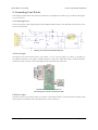
5.a. Connecting Power
The two main ways of powering the Wixel are the USB port and the VIN pin. The schematic of the Wixel’s power
system is shown below:
Wixel power system schematic diagram.
VIN Power Input
The Wixel can be powered from VIN if you connect a 2.7–6.5 V power supply (e.g. battery or regulator) to
the GND and VIN pins. The negative terminal should be connected to GND. The positive terminal should be
connected to VIN. It is okay to have both USB and VIN connected at the same time.
The Wixel can be powered from an
external power source connected to VIN.
USB Power Input
The Wixel can be powered from USB if you connect a USB cable and leave VIN disconnected. The Wixel will
draw its power from USB if VIN is disconnected or it is below about 4 V.
5. Connecting Your Wixels
Page 20 of 49
Pololu Wixel User's Guide
© 2001–2010 Pololu Corporation
The Wixel can be powered from USB.
3V3 Power Output
The Wixel’s 3V3 pin gives access to the output of the Wixel’s 3.3 V regulator. If the Wixel’s power supply
drops below approximately 3.5 V, the 3V3 output will be less than 3.3 V. Normally this output can provide up to
150 mA, but if the Wixel’s power supply is above 5 V then it is limited to 100 mA. You can use 3V3 to power
your own 3.3 V devices.
VALT Power Output
VALT provides access to the input pin of the Wixel’s 3.3 V regulator, which is connected through a diode to VIN
or to the USB bus voltage, depending on which power source is connected. You can use VALT to power your
own circuits as long as you do not draw more than about 500 mA.
For example, if you leave VIN disconnected, VALT can power 5V devices.
Low Power Considerations
The CC2511F32 is capable of a sleep mode (PM2) where the chip draws less than 1 μA and is still capable of
waking itself up. Without modifying the Wixel’s hardware, it is possible to power it from VIN and get the current
consumption down to around 100 μA. Most of that current is consumed by the Wixel’s 3.3 V regulator. To get rid
of it, you will need to sever the output pin of the regulator and power the Wixel directly from the 3V3 pin with a
2.0–3.6 V power supply. For details on how to do this, please contact Pololu.
Please note that currently none of the Wixel apps support low power modes, so the Wixel will draw approximately
30 mA at all times. To make your Wixel operate with low power you would have to write your own app or modify
one of the existing apps. You will need to make sure that all of the I/O lines are either outputs or get pulled high
or low: an input line at an intermediate voltage can consume several microamps of extra current.
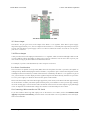
5.b. Connecting a Microcontroller via TTL Serial
If you have loaded a Wixel app that employs one of the Wixel’s two UARTs (such as the Wireless Serial
App [http://www.pololu.com/docs/0J46/9.b]), then the Wixel can send and/or receive asynchronous TTL serial bytes
from a microcontroller.
5. Connecting Your Wixels
Page 21 of 49
Pololu Wixel User's Guide
Making serial connections between a
Wixel and a 5V microcontroller.
© 2001–2010 Pololu Corporation
Making serial connections between a
Wixel and a 3.3V microcontroller.
To connect your microcontroller to a Wixel for serial communication, make these connections:
• GND: Connect the ground (also known as GND or VSS) of your microcontroller to one of the GND pins
on the Wixel. This connection is required.
• TX: If you want the microcontroller to be able to receive serial bytes from the Wixel, connect the Wixel’s
TX line to the microcontroller’s RX line.
• RX: If you want your microcontroller to be able to send serial bytes to the Wixel, connect the
microcontroller’s TX line to the Wixel’s RX line. The Wixel’s RX line is not 5 V tolerant. If your
microcontroller is running at 5 V (or any voltage significantly above 3.3 V) then you will need to add extra
components to ensure that your microcontroller never drives the Wixel’s RX line higher than 3.3 V. A simple
voltage divider consisting of 2 resistors as shown in the diagram above will suffice. The Wixel’s RX line has
an internal 20 kΩ pull-up resistor.
• RST: If you want the microcontroller to be able to reset the Wixel, then connect the Wixel’s RST line
to any free general-purpose I/O (GPIO) line on the microcontroller. The microcontroller can drive this line
low to reset the Wixel and then stop driving the line to release the Wixel from reset. The Wixel’s RST line
is not 5 V tolerant. If your microcontroller is running at 5 V (or any voltage significantly above 3.3 V) then
you must avoid driving the Wixel’s RST line high. If that is not possible, then you could put a diode between
the Wixel’s RST line and the microcontroller’s GPIO to prevent current from flowing in the wrong direction
(from the GPIO). The connection to RST is optional and not required for sending or receiving data.
Please refer to the documentation of your specific Wixel app to determine the location of the TX pin(s) and RX
pin(s).
5.c. Connecting Buttons and Starting the Bootloader
In order to load a new app or new settings onto your Wixel (or read the Wixel’s flash memory) you will need
to get it into bootloader mode. Most Wixel apps support a special USB command for putting the Wixel into
bootloader mode and the Wixel Configuration Utility can send that command automatically when you try to
access the Wixel’s flash. However you may find yourself in a situation where that method will not work. This can
happen for two reasons:
• You accidentally loaded a malfunctioning program onto the Wixel that is incapable of responding to the
special USB command.
• You loaded a program which uses a different type of USB interface or no USB interface. In this case,
check the documentation of the app to see if there is a convenient way for getting the Wixel into bootloader
mode.
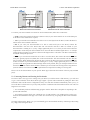
No matter what state the Wixel is in, you can manually get it into bootloader mode by connecting USB, setting
P2_2 high, and resetting the Wixel.
5. Connecting Your Wixels
Page 22 of 49
Pololu Wixel User's Guide
© 2001–2010 Pololu Corporation
There are two main ways to accomplish this.
One way is to disconnect the Wixel from any possible power sources, connect P2_2 to 3V3 using a wire, and then
plug it into USB.
Using a wire to put the Wixel into bootloader mode.
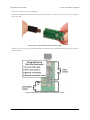
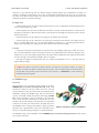
Another way to is to wire a bootloader button and a reset button to the Wixel and follow the procedure shown in
the picture below:
Using pushbuttons to put the Wixel into bootloader mode.
5. Connecting Your Wixels
Page 23 of 49
Pololu Wixel User's Guide
© 2001–2010 Pololu Corporation
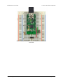
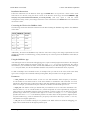
Wixel on breadboard with a bootloader button and reset button
connected.
5. Connecting Your Wixels
Page 24 of 49
Pololu Wixel User's Guide
© 2001–2010 Pololu Corporation
6. Using a Virtual COM Port
Most of the available Wixel apps implement a USB interface that consists of a single virtual COM (serial) port.
This interface allows you to send and receive bytes from the Wixel in the same way you would send and receive
bytes from any other serial port on your computer.
6.a. Determining the Port Name
To connect to a COM port, you usually have to know the name of the port.
In Windows, the port name will be something like “COM4” and you can determine the port name by selecting the
Wixel in the Wixel Configuration Utility and looking at the “Port Name” property displayed below. You can also
find out the port name by looking the “Ports (COM & LPT)” list in your Device Manager.
Windows Tip: Besides having names like “COM5” and “COM6”, the virtual COM ports provided
by the Wixel also have names like “\\.\USBSER000” and “\\.\USBSER001”. These names are
assigned sequentially whenever a device with a virtual COM port is plugged in. If you only have
one device with a virtual COM port plugged into your computer, the name “\\.\USBSER000” will
usually be assigned to it. These names will work with most programs that allow you to specify
arbitrary port names.
6.b. Using a Terminal Program
There are many free terminal programs available which are capable of sending and receiving bytes on a
virtual COM port. These programs include PuTTY [http://www.chiark.greenend.org.uk/~sgtatham/putty/] (Windows
or Linux), Tera Term [http://hp.vector.co.jp/authors/VA002416/teraterm.html] (Windows), and Br@y
Terminal [http://sites.google.com/site/terminalbpp/] (Windows). Advanced users developing scripted applications may
prefer the free terminal program kermit [http://www.columbia.edu/kermit/ck80.html]. To use any of these terminal
programs with the Wixel, you must specify the port name (see Section 6.a) and the baud rate. The baud rate may
or may not affect anything; see your application’s documentation. The characters you type will be transmitted on
the programmer’s TX line. Bytes received by the programmer on the RX line will be displayed on the screen by
the terminal program.
Typical terminal programs will allow you to choose several other settings besides the baud rate. If you are not
sure what settings to use, then you should pick 8 data bits, 1 stop bit, no parity, and no flow control.
Typical terminal programs will not allow you to use the serial control signals, but Br@y terminal does. You can
click the “DTR” and “RTS” buttons to change the state of the DTR and RTS signals. The state of the CTS, CD,
DSR, RI, DTR, and RTS signals are indicated by the colors of the corresponding buttons.
6. Using a Virtual COM Port
Page 25 of 49
Pololu Wixel User's Guide
© 2001–2010 Pololu Corporation
PuTTY is a free Windows terminal program that can send and receive bytes on a
serial port.
If you need to send and receive non-ASCII bytes, you can use the Pololu Serial Transmitter Utility for
Windows [http://www.pololu.com/docs/0J23] or Br@y Terminal.
6.c. Writing PC Software to Use a Serial Port
You can write your own computer program that communicates with a serial port. The freely available Microsoft
.NET framework contains a SerialPort [http://msdn.microsoft.com/en-us/library/system.io.ports.serialport.aspx] class that
makes it easy to read and write bytes from a serial port. Here is some example C# .NET code that uses a serial
port:
// Choose the port name and the baud rate.
System.IO.Ports.SerialPort port = new System.IO.Ports.SerialPort("COM4", 115200);
// Connect to the port.
port.Open();
// Transmit two bytes on the TX line: 1, 2
port.Write(new byte[]{1, 2}, 0, 2);
// Wait for a byte to be received on the RX line.
int response = port.ReadByte();
// Show the user what byte was received.
MessageBox.Show("Received byte: " + response);
// Disconnect from the port so that other programs can use it.
port.Close();
6. Using a Virtual COM Port
Page 26 of 49
Pololu Wixel User's Guide
© 2001–2010 Pololu Corporation
7. Ensuring a Good Radio Signal
Here are some tips for improving the quality of the radio signals sent between a pair of Wixels:
• Reduce the distance between the Wixels, if possible.
• Try different frequencies. Most Wixel apps that use the radio have a radio_channel parameter that
determines what frequency will be used. By switching to a different channel you might be able to avoid
interference from other nearby 2.4 GHz radios. You might even want to buy a spectrum analyzer such as
the Wi-Spy [http://www.metageek.net/products/wi-spy/] to find out which frequencies in your area have the least
activity.
• Remove objects that are very close to the Wixel’s antenna. For example, if the Wixel has no header pins
installed and it is resting flat on your desk, find a way to get the Wixel at least an inch or two above the desk.
• Reduce obstructions between the two Wixels. Many objects can interfere with 2.4 GHz radio waves,
including walls, trees, people and anything with water in it.
• Try different Wixel orientations. The Wixel’s antenna sends and receives better in some directions than
others.
7. Ensuring a Good Radio Signal
Page 27 of 49
Pololu Wixel User's Guide
© 2001–2010 Pololu Corporation
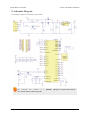
8. Schematic Diagram
The schematic diagram of the Wixel is shown below:
The
schematic
also
available as
(51k pdf).
a
printable
pdf [http://www.pololu.com/file/download/
wixel_schematic.pdf?file_id=0J463]
8. Schematic Diagram
Page 28 of 49
Pololu Wixel User's Guide
© 2001–2010 Pololu Corporation
9. Wixel Apps
This section describes the available Wixel apps.
9.a. Example App: Blink LED
This is an example app that blinks the red LED with a configurable period. See Section 3.d for a tutorial on using
this app.
Download
link:
example_bink_led_v1.0.wxl [http://www.pololu.com/file/download/
example_blink_led_v1.0.wxl?file_id=0J449]
(11k wxl)
9.b. Wireless Serial App
Overview
This app allows you to connect two Wixels together to make a
wireless, bidirectional, lossless serial link. It uses an RF bit rate
of 350 kbps, is capable of carrying up to 10 KB of payload data
per second, and can reach a range of approximately 40 feet
(under typical conditions indoors). You can also use it to turn
one Wixel into a USB-to-TTL serial adapter.
This app can run on multiple pairs of Wixels as long as each pair
operates on a different radio channel (the channels should be
separated by 2 to avoid interference).
This app is designed for pairs of Wixels; it will not work
properly if three or more Wixels are broadcasting on the same
radio channel.
Wireless PC control of a 3pi robot using a
pair of Wixels.
Installation Instructions
Download Wireless Serial App v1.2 [http://www.pololu.com/file/download/wireless_serial_v1.2.wxl?file_id=0J468] (24k
wxl). Open it with the Wixel Configuration Utility, choose your parameters, and then write it to two Wixels. See
Section 4 for more information on how this is done.
Default Pinout
Pin
Function
P1_0 DTR
general-purpose output pin
P1_1 RTS
general-purpose output pin
P1_2 DSR
general-purpose input pin
P1_3 CD
general-purpose input pin
P1_5 PA_PD
radio transmit debug output
P1_6 TX
transmits serial data (0–3.3 V)
P1_7 RX
receives serial data (0–3.3 V, not 5 V tolerant)
P0_0 Arduino DTR output reserved for future use
9. Wixel Apps
Page 29 of 49
Pololu Wixel User's Guide
© 2001–2010 Pololu Corporation
Description
This device appears to the USB host as a Virtual COM Port (with USB product ID 0x2200). If you are using
Windows, you should see an entry labeled “Wixel” in your Device Manager in the “Ports (COM & LPT)”
category while the app is running.
There are three basic serial modes that can be selected:
1. USB-to-Radio: Serial bytes from the USB virtual COM port get sent to the radio and vice versa.
2. UART-to-Radio: Serial bytes from the UART’s RX line get sent to the radio and bytes from the radio
get sent to the UART’s TX line.
3. USB-to-UART: Just like a normal USB-to-TTL serial adapter, bytes from the virtual COM port get sent
on the UART’s TX line and bytes from the UART’s RX line get sent to the virtual COM port.
You can select which serial mode you want to use by setting the serial_mode parameter to the appropriate number
(from the list above) or you can leave the serial mode at 0 (which is the default). If the serial_mode is 0, then the
Wixel will automatically choose a serial mode based on how it is being powered as described in the table below,
and it will switch between the different serial modes on the fly.
Auto-Detect Serial Mode
(serial_mode = 0)
Power Source
Serial Mode
USB only
USB-to-Radio
VIN only
UART-to-Radio
USB and VIN
USB-to-UART
The RX pin has an internal 20 kΩ pull-up resistor.
The PA_PD pin (P1_5) is a debugging output that goes low while the Wixel is transmitting a packet on the radio.
Indicator LEDs
The green LED behaves as described in Section 1.a, and also flickers when there is data transferred over USB.
The yellow LED is on when VIN power is detected.
The red LED should not turn on; if it does then this indicates a bug in the application
Control Signals
In addition to relaying bidirectional serial data, this app also relays the values of four control signals: DTR, RTS,
DSR, and CD. The names of these control signals come from the RS-232 protocol, but in this app they do not
actually have the same role as they have in that protocol: they are general purpose digital control signals that can
carry any kind of data that you want them to, as long as that data changes slowly (on the order of 5 Hz or slower)
and is limited to two bits in each direction.
In USB-to-Radio mode, the DTR and RTS signals from USB are transmitted wirelessly to the other Wixel, while
the control signals wirelessly received from the other Wixel are relayed to USB as DSR and CD.
9. Wixel Apps
Page 30 of 49
Pololu Wixel User's Guide
© 2001–2010 Pololu Corporation
In UART-to-Radio mode, the DSR and CD signals from the digital input pins are transmitted wirelessly to the
other Wixel, while the control signals wirelessly received from the other Wixel are relayed to the DTR and RTS
output pins.
In USB-to-UART mode, the DTR and RTS signals from USB are relayed to the corresponding output pins, while
the values of the DSR and CD input pins are relayed to USB.
If two Wixels are communicating wirelessly with each other and both are in UART-to-Radio mode or both are
in USB-to-Radio mode, then the correspondence between the control lines is as follows: DSR on one Wixel
corresponds to DTR on the other Wixel, while RTS on one Wixel corresponds to CD on the other Wixel.
The default configuration of this app (as shown in the table above) gives the Wixel two inverted output pins (DTR
and RTS), and two inverted input pins (DSR and CD). These pins are inverted, which means that a logical value
of 0 corresponds to high voltage (usually 3.3 V), while a logical value of 1 corresponds to 0 V (GND).
By changing the configuration parameters (see below), you can disable these signals, reassign them to different
I/O lines, or add non-inverted inputs and outputs.
Any pin configured as an input will have an internal 20 kΩ pull-up resistor unless it is assigned to P1_0 or P1_1,
which do not have pull-up or pull-down resistors.
You do not have to connect anything to the control signal pins in order to send and receive serial
data. These pins are optional.
General Parameters
• serial_mode: Selects the serial mode (1–3, see list above) or auto-detect serial mode (0). The default is 0.
• baud_rate: The baud rate to use for the UART, in bits per second. The default is 9600. We recommend
not exceeding 115200. This parameter has no effect on serial communication over the virtual COM port
(USB).
• radio_channel: The channel number is from 0 to 255 and determines which frequency to broadcast
on. The default is 128. Wixels must be on the same channel to communicate with each other. To avoid
interference, Wixels that aren’t supposed to talk to each other should be at least 2 channels away from each
other. For example, you could have one pair of Wixels on channel 128 and another pair on 130.
Pin Assignment Parameters
The following parameters can be used to reassign the control signals to different pins on the Wixel. The value of
each parameter must be the number of an unused pin on the Wixel. The number can be computed by multiplying
the first digit in the pin name by 10 and adding it to the second digit in the pin name. For example, if you wanted
to assign the DSR pin to P1_2, you would set nDSR_pin to 12. To disable a signal (assign it to no pin), set the
corresponding parameter to -1.
• nDTR_pin: The pin assignment for the inverted DTR output. The default is 10 (P1_0).
• nRTS_pin: The pin assignment for the inverted RTS output. The default is 11 (P1_1).
• nDSR_pin: The pin assignment for the inverted DSR input. The default is 12 (P1_2).
• nCD_pin: The pin assignment for the inverted CD input. The default is 13 (P1_3).
• DTR_pin: The pin assignment for the non-inverted DTR output. The default is -1 (disabled).
• RTS_pin: The pin assignment for the non-inverted RTS output. The default is -1 (disabled).
9. Wixel Apps
Page 31 of 49
Pololu Wixel User's Guide
© 2001–2010 Pololu Corporation
• DSR_pin: The pin assignment for the non-inverted DSR input. The default is -1 (disabled).
• CD_pin: The pin assignment for the non-inverted CD input. The default is -1 (disabled).
• arduino_DTR_pin: The pin assignment for an output that is reserved for future use. The default is 0
(P0_0).
You should not simultaneously enable the non-inverted and inverted input for the same signal. Specifically, either
nCD_pin or CD_pin should be -1 and either nDSR_pin or DSR_pin should be -1.
Example Uses
1. This application can be used to make a wireless serial link between two microcontrollers, with no USB
involved (except for initially configuring the Wixels). To do this, use the UART-to-Radio mode on both
Wixels.
2. This application can be used to make a wireless serial link between a computer and a microcontroller.
Use USB-to-Radio mode on the Wixel that is connected to the computer and use UART-to-Radio mode on
the Wixel that is connected to the microcontroller. If you are powering both Wixels in the usual way, you
should be able to use auto-detect serial mode (serial_mode = 0).
3. If you are doing option 2 above and using the the auto-detect serial mode (serial_mode = 0), then
you have the option to (at any time) plug a USB cable directly into the Wixel that is connected to your
microcontroller to establish a more direct (wired) serial connection with the microcontroller. (You would, of
course, have to tell your computer to switch to the other COM port when you do this.)
Caveats
Data will be lost if the Wixel receives bytes on the RX line faster than the radio can convey them to the other
Wixel. If you have trouble, try reducing the amount of data sent to the RX line by lowering the baud rate or adding
delays to your microcontroller’s code.
Caution: The Wixel’s I/O lines are not 5V tolerant. You must use level-shifters, diodes, or voltage
dividers to connect the Wixel to outputs from 5V systems. Also, avoid drawing more current from an
I/O line than it can provide (see the discussion of P1_0 and P1_1 in Section 1.a). Avoid connecting
multiple output pins together.
Versions
• Wireless Serial App v1.2 [http://www.pololu.com/file/download/wireless_serial_v1.2.wxl?file_id=0J468] (24k wxl),
released 2011-04-06: Added support for control signals. As a result, the radio protocol used is NOT
compatible with earlier versions. Also fixed a glitch on the TX line that occurred on upon power-up or
reset. Added blinking behavior to the green LED to indicate USB data transfer.
• Wireless Serial App v1.1 [http://www.pololu.com/file/download/wireless_serial_v1.1.wxl?file_id=0J461] (18k wxl),
released 2011-03-23: Improved the radio protocol to fix a problem in v1.0 where if one Wixel resets but the
other Wixel does not, then (depending on the state of the other Wixel) there is a 50% probability that the next
radio packet sent in either direction will be ignored by the receiver.
• Wireless Serial App v1.0 [http://www.pololu.com/file/download/wireless_serial_v1.0.wxl?file_id=0J447] (18k wxl),
released 2011-03-22: Initial release.
9. Wixel Apps
Page 32 of 49
Pololu Wixel User's Guide
© 2001–2010 Pololu Corporation
9.c. USB-to-Serial App
Overview
This app allows you to turn a Wixel into a USB-to-TTL serial
adapter capable of baud rates up to 350,000 bps. While this app
does not use the radio, it has more features than the USB-toUART mode of the Wireless Serial App (see Section 9.b).
Installation Instructions
Download USB-to-Serial App v1.0 [http://www.pololu.com/file/
download/usb_serial_v1.0.wxl?file_id=0J464] (13k wxl). Open it with
the Wixel Configuration Utility and write it to a Wixel. See
Section 4 for more information on how this is done.
Wixel programmable USB wireless
module (fully assembled) with USB cable
connected.
Pinout
Pin
Function
P1_0 DTR general purpose output pin controlled by computer
P1_1 RTS
general purpose output pin controlled by computer
P1_2 DSR general purpose input pin reported to computer
P1_3 CD
general purpose input pin reported to computer
P1_6 TX
transmits serial data from computer
P1_7 RX
receives data and sends it to the computer
Description
After you have loaded this app onto a Wixel, the Wixel will appear to the computer as Virtual COM Port (with
USB product ID 0x2200). If you are using Windows, you should see an entry labeled “Wixel” in your Device
Manager in the “Ports (COM & LPT)” category while the app is running. You can connect to this COM port
using a terminal program in order to send and receive data on the TX and RX lines. Typical terminal programs
will allow you to set the baud rate, parity type, and number of stop bits. Some terminal programs will allow you
to use the control signals (DTR, RTS, DSR, and CD). For more information, on how to use a virtual COM port,
see Section 6.
This app supports all integer baud rates between 23 and 350,000 bps.
This app supports all the different types of parity: None, Odd, Even, Mark and Space.
This app supports 1 stop bit or 2 stop bits mode.
The RX line has an internal pull-up resistor, so you can leave this line disconnected.
The DSR and CD input pins have internal pull-up resistors, so when they are disconnected they will read as high
(logical 0).
The DTR and RTS output pins are designed for high current (see the information on P1_0 and P1_1 in Section
1.a).
9. Wixel Apps
Page 33 of 49
Pololu Wixel User's Guide
© 2001–2010 Pololu Corporation
The control signals are all inverted, which means that a logical 0 corresponds to a high voltage (3.3 V) and a
logical 1 corresponds to a low voltage (0 V).
This app will discard bytes received on the RX line that have framing errors or parity errors, and it will also throw
out bytes if there is an RX buffer overrun. An RX buffer overrun should not happen if you are using a baud rate
of 350,000 bps or less.
Example Uses
• The TX line can be used to send commands to a microcontroller or other serial device.
• The RX line can be used to receive data from a microcontroller or other serial device.
• The DTR and RTS lines are general-purpose digital outputs that can be used to control something (such
as an LED) from a computer.
• The DSR and CD lines are general-purpose digital inputs that can be connected to a sensor or other circuit
and read from a computer.
Caveats
• The CC2511’s UARTs do not actually support 1.5 stop bits, so if you try to set the number of stop bits to
1.5, this app will use 1 stop bit instead.
• The CC2511’s UARTs do not support having 2 stop bits very well, so if you set the number of stop bits to
2, this app may fail to detect framing errors that occur during the second stop bit. Also, the next byte received
after the framing error occurred may be discarded even if that byte is valid. This problem only applies to
receiving bytes on the RX line; this app has no problem transmitting bytes on the TX line with 2 stop bits.
Caution: The Wixel’s I/O lines are not 5V tolerant. You must use level-shifters, diodes, or voltage
dividers to connect the Wixel to outputs from 5V systems. Also, avoid drawing more current from an
I/O line than it can provide (see the discussion of P1_0 and P1_1 in Section 1.a). Avoid connecting
multiple output pins together.
9.d. I/O Repeater App
Overview
This app allows you to wirelessly extend the reach of your
microcontroller’s I/O lines up to 40 feet using two or more
Wixels. An input pin on one Wixel can be mapped to an output
pin on another Wixel. When the input pin reads high, the output
pin will be driven high (3.3 V) and when the input pin reads low,
the output pin will be driven low (0 V). Each Wixel can have up
to 15 input pins, 15 output pins, or a mixture of input and output
pins. Each input pin can map to one or more output pins on one
or more Wixels.
Installation Instructions
Download I/O Repeater App v1.0 [http://www.pololu.com/file/
download/io_repeater_v1.0.wxl?file_id=0J465] (18k wxl). Open it with the Wixel Configuration Utility, choose your
settings, and write it to two or more Wixels. See Section 4 for more information on how this is done.
9. Wixel Apps
Page 34 of 49
Pololu Wixel User's Guide
© 2001–2010 Pololu Corporation
Description
The following 15 pins on each Wixel can be used as inputs or outputs (or be disabled):
• All the pins on Port 0: P0_0, P0_1, P0_2, P0_3, P0_4, P0_5.
• All the pins on Port 1: P1_0, P1_1, P1_2, P1_3, P1_4, P1_5, P1_6, P1_7.
• Pin P2_1 (the red LED pin).
The behavior of each pin is determined by its link ID, which is a parameter that you can set individually for each
pin on each Wixel using the Wixel Configuration Utility. A link ID of 0 means the pin will be disabled (it will be
an input but its input value will not have any effect). A negative link ID between -1 and -127 means that the pin
will be a digital input and its value will be transmitted over the radio. A positive link ID between 1 and 127 means
that the pin will be a digital output and its output value will be determined by the input value of the pin with the
opposite (negated) link ID on another Wixel. For example, if the P1_3 pin on one Wixel has a link ID of -13, then
it will be a digital input and its value will be reflected on all the output pins that have a link ID of 13 on all the
other Wixels. Input pins do not have any effect on output pins that are on the same Wixel.
If a Wixel is running this app and has one or more pins configured to be inputs, then it will transmit a single radio
packet every 10 ms (approximately) that contains input values and link IDs of all of its inputs. Any other Wixel
that successfully receives this packet will process it and use it to update the state of its output pins.
This app will work with more than two Wixels on the same radio channel. In that case, make sure that you do not
have multiple input pins on different Wixels with the same link ID: otherwise, the corresponding output pin(s)
will change state unpredictably whenever there is a conflict between the different input pins. It is OK to have
muliple output pins with the same link ID.
Every pin configured as an input has an internal 20 kΩ pull-up resistor except P1_0 and P1_1, which float when
they are inputs. This means that if you leave the input pin disconnected, it will be pulled high by default.
Each output pin will drive low (0 V) by default before any radio packets are received that change its state.
After you have loaded this app onto a Wixel, the Wixel will appear to the computer as Virtual COM Port (with
USB product ID 0x2200). If you are using Windows, you should see an entry labeled “Wixel” in your Device
Manager in the “Ports (COM & LPT)” category while this app is running. You can not send or receive data on this
COM port. Its only purpose is to let the Wixel Configuration Utility easily get the Wixel into bootloader mode.
Parameters
• radio_channel: The channel number is from 0 to 255 and determines which frequency to broadcast
on. The default is 128. Wixels must be on the same channel to communicate with each other. To avoid
interference, Wixels that aren’t supposed to talk to each other should be at least 2 channels away from each
other. For example, you could have one pair of Wixels on channel 128 and another pair on 130.
• Pm_n_link: The link ID of pin Pm_n where m is the port number (0–2) and n is the pin number (0–7).
Default Settings
The default settings are:
Pin
P0_0
Link ID
-1
P2_1 (red LED pin) 1
9. Wixel Apps
Function
Input with pull-up resistor.
Output linked to P0_0 on the other Wixel.
Page 35 of 49
Pololu Wixel User's Guide
© 2001–2010 Pololu Corporation
Therefore, if you load this app onto two Wixels using the default settings, they should behave as follows: If
nothing is connected to either Wixel’s P0_0 line, the red LEDs on both Wixels will be on. If you connect the
P0_0 line of one Wixel to GND using a wire, then you should see the red LED on the other Wixel turn off. This
demonstrates the basic operation of the app.
Example Uses
• A Wixel output pin can be used to control an LED. Be sure to use an appropriate current-limiting resistor
in series with the LED (e.g. 1 kΩ)
• A Wixel input pin can be used to read the state of a button or switch. Connect the button or switch between
the input pin and GND, so that when the switch is open the pin will read high, and when the switch is closed
the pin will read low.
• A Wixel output pin can be connected to an input pin on another microcontroller.
• A Wixel input pin can be connected to an output pin on another microcontroller. The output must not
drive to a voltage higher than 3.3 V. If your microcontroller is running at 5 V you could get around this by
using a diode or putting your output pin into open-collector mode (never drive high).
Caveats
• A change on an input pin will usually be reflected on the corresponding output pin(s) within 10–100 ms,
but every radio packet has a chance of being lost so there is no guaranteed latency. Therefore, this app is only
suitable for very low-speed digital signals such as the signal from a pushbutton or the signal used to control
an LED. This app is not suitable for PWM or RC servo signals.
• This app uses digital I/O which means that every reading is transmitted as a 0 or 1. This app does not
support analog voltages.
Caution: The Wixel’s I/O lines are not 5V tolerant. You must use level-shifters, diodes, or voltage
dividers to connect the Wixel to outputs from 5V systems. Also, avoid drawing more current from an
I/O line than it can provide (see the discussion of P1_0 and P1_1 in Section 1.a). Avoid connecting
multiple output pins together.
9.e. ShiftBrite App
Overview
This app allows you to wirelessly control a chain of one more
ShiftBrite [http://www.pololu.com/catalog/product/1240] RGB LED
modules at a distance of 40 feet or more from a PC. You will
need two Wixels to set up the wireless link: one connected to the
ShiftBrites, running the ShiftBrite app, and one connected to
your PC with USB, running the Wireless Serial App (Section
9.b). Using a terminal or your own software, you can send a
series of hex characters indicating the desired color for each
module to the virtual COM port. The characters are transmitted
wirelessly, received by the remote Wixel, decoded, and sent to
the ShiftBrite chain, causing each module to light up with the
specified color. Approximately 1000 color commands can be
sent per second, allowing large displays or smooth animations.
A Wixel controlling a chain of ShiftBrites.
The ShiftBrite App is also compatible with the ShiftBar [http://www.pololu.com/catalog/product/1242], which uses the
same control electronics.
9. Wixel Apps
Page 36 of 49
Pololu Wixel User's Guide
© 2001–2010 Pololu Corporation
Installation Instructions
Follow the instructions for the Wireless Serial App in Section 9.b to set up and test a basic wireless serial
link between two Wixels, using the latest version of the Wireless Serial App. Download ShiftBrite App
v1.1 [http://www.pololu.com/file/download/shiftbrite_v1.1.wxl?file_id=0J469] (20k wxl). Open it with the Wixel
Configuration Utility, choose your settings, and write it to one of the Wixels. See Section 4 for more information
on how this is done.
Connecting the Wixel to the ShiftBrite chain
The following connections should be made between the Wixel running the ShiftBrite App and the first ShiftBrite
in the chain:
Wixel ShiftBrite Function
P1_4
EI
Enable
P1_5
CI
Clock
P1_6
DI
Data
P1_7
LI
Latch
GND
GND
Ground
Additionally, the Wixel and ShiftBrites may share the same VIN as long as the voltage requirements for both
modules are satisfied. For initial testing, you may alternatively use VALT to power the ShiftBrites from USB (see
Section 5.a).
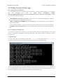
Using the ShiftBrite App
After making the correct connections and applying power, open a terminal program and connect to the COM port
created by the Wixel running the Wireless Serial App. Type ffffff. As you type the characters, they will be
echoed back to your terminal. Press Enter, and the first ShiftBrite in your chain will light up in white. Then type
ff0000 and press Enter; now the first ShiftBrite should be red, and the second should be white (if present).
To shift out multiple color commands at once, for example when you want to set the colors of the entire chain,
type a series of single-color commands without pressing Enter, then press Enter once to apply them all.
Parameters
• radio_channel: The channel number is from 0 to 255 and determines which frequency to broadcast
on. The default is 128. Wixels must be on the same channel to communicate with each other. To avoid
interference, Wixels that aren’t supposed to talk to each other should be at least 2 channels away from each
other. For example, you could have one pair of Wixels on channel 128 and another pair on 130.
• input_bits: The number of bits per channel that you would like to use to send color information. The
allowed values are 1 to 16, and the default is 8, which corresponds to colors represented by 6-digit hex
values. However, the ShiftBrite supports 10 bits of resolution, so choose a value of 10 to make use of its full
dynamic range. In this case, you must send 9 digits to set a color. For example, 3ff3ff3ff is the brightest
possible white and 001000000 is the dimmest possible red. Other values for this parameter might be useful
in special situations (e.g. 4 bits of resolution lets you specify a full color in three bytes, such as f00 for red,
which allows for a higher update rate).
• echo_on: Set to 0 to disable echoing of every character sent. While echoes are useful for debugging, you
might want to disable them for the highest possible speed.
9. Wixel Apps
Page 37 of 49
Pololu Wixel User's Guide
© 2001–2010 Pololu Corporation
Data Format
The data consists of a series of red, green, and blue (RGB) values, as ASCII hex strings. Each value contains
from 1 to 4 characters, depending on the value of input_bits, specifying a number from 0 to 2input_bits-1. When
a complete set of R, G, and B values has been received, the values are multiplied or divided by the appropriate
factor to match the 10-bit ShiftBrite data format and shifted out to the ShiftBrite chain. An Enter character (ASCII
10 or 13) causes the Latch pin to be toggled, instantly setting each ShiftBrite to its new color.
Tips
• The yellow LED is normally on, and flickers whenever data is received from the radio, which might be
useful for debugging your wireless connection.
• You can use wires with pre-crimped terminals [http://www.pololu.com/catalog/category/71] and crimp
connector housings [http://www.pololu.com/catalog/category/70] to make a custom cable between the Wixel and
the ShiftBrite chain.
Versions
• Shiftbrite App v1.1 [http://www.pololu.com/file/download/shiftbrite_v1.1.wxl?file_id=0J469] (20k wxl), released
2011-04-06: Changed the yellow LED to be normally on, but flicker whenever data is received from the
radio. This version is only compatible with Wireless Serial App v1.2 and later.
• Shiftbrite App v1.0 [http://www.pololu.com/file/download/shiftbrite_v1.0.wxl?file_id=0J466] (18k wxl), released
2011-03-28: Initial release. In this version, the yellow LED starts off and turns on after the first Enter is
received. This version is only compatible with Wireless Serial App versions 1.0 and 1.1.
9.f. Wireless Tilt Mouse App
Overview
This app allows you to make a wireless tilt mouse for your
computer. By tilting the mouse, you can control the position of
the mouse cursor. The mouse also supports two buttons for
clicking.
This app requires two Wixels: a transmitter and a receiver. The
transmitter Wixel detects a tilt using an accelerometer and
wirelessly transmits that information to the receiver Wixel,
which relays it to the computer as mouse movements. The
receiver appears to the computer as a standard USB Human
Interface Device (HID); after the Wixels have been configured,
no driver installation is necessary to use the mouse.
Wireless tilt mouse made with two
Wixels and an accelerometer.
Parts Needed
There are many different ways to build this project. Here are the parts we used:
• Wixel Pair (Fully Assembled) + USB Cable [http://www.pololu.com/catalog/product/1338]
• MMA7361L 3-Axis Accelerometer ±1.5/6g [http://www.pololu.com/catalog/product/1246]
• 3-AAA Battery Holder, Enclosed with Switch [http://www.pololu.com/catalog/product/1147] and 3 AAA
batteries
• 270-Point Breadboard [http://www.pololu.com/catalog/product/350]
• Mini Pushbutton Switches [http://www.pololu.com/catalog/product/1400]
9. Wixel Apps
Page 38 of 49
Pololu Wixel User's Guide
© 2001–2010 Pololu Corporation
You will need wires and connectors to make the electrical connections. We suggest our jumper wire
kits [http://www.pololu.com/catalog/category/29] or premium jumper wires [http://www.pololu.com/catalog/category/65].
You will need a soldering iron [http://www.pololu.com/catalog/category/5] to solder the included header pins into the
accelerometer.
The pushbuttons are optional, and any normally-open (NO) pushbutton or switch will work. If you want to have
both a left mouse button and a right mouse button you should get two pushbuttons. Note that only one button (on
P1_2) is shown in the picture above.
Pinout of Transmitter Wixel
Pin
Function
P0_1 analog input for vertical mouse speed
P0_2 analog input for horizontal mouse speed
P1_2 left mouse button input, internally pulled high
P1_7 right mouse button input, internally pulled high
Wixel Configuration
Download the Wireless Tilt Mouse App [http://www.pololu.com/file/download/wireless_tilt_mouse_v1.0.wxl?file_id=0J470]
(26k wxl). Open it with the Wixel Configuration Utility, choose your settings, and write it to the transmitter Wixel.
The transmitter Wixel should now appear to your computer as a USB virtual COM port (with USB product ID
0x2200). You can not send or receive data on this COM port. Its only purpose is to let the Wixel Configuration
Utility easily get the transmitter Wixel into bootloader mode when the transmitter Wixel is connected to the
computer via USB.
Download
the
Wireless
Tilt
Mouse
Receiver
App [http://www.pololu.com/file/download/
(15k wxl). Open it with the Wixel Configuration Utility, choose
your settings, and write it to the receiver Wixel. The receiver Wixel should now appear to your computer as a
Human Interface Device. If you are using Windows there should be a new entry entitled “HID-compliant mouse”
in your Device Manager in the “Mice and other pointing devices” section. The receiver will also show up as a
keyboard, but it does not use that interface.
wireless_tilt_mouse_receiver_v1.0.wxl?file_id=0J471]
The Wixel Configuration Utility does not yet detect Wixels with USB HID interfaces. Therefore,
if you need to reconfigure your receiver Wixel, you will need to manually get it into bootloader
mode (set pin P2_2 high and reset – although this app monitors P2_2 all the time so the reset is not
strictly necessary).
Assembly
With the battery pack switched off, connect power for the transmitter Wixel. The black wire from the battery pack
should connect to a GND pin on the Wixel. The red wire from the battery pack should connect to VIN. To test the
connection, turn on the battery pack: the transmitter Wixel’s yellow LED should turn on. Remember to turn off
the battery pack while you are making connections.
Connect the GND of the Wixel to the GND (ground) pin of the accelerometer. Connect power for the
accelerometer. The MMA7361L accelerometer we used can run off of 3.3 V and draws relatively little current, so
we powered it from the Wixel’s 3V3 line by connecting 3V3 to the accelerometer’s VDD.
9. Wixel Apps
Page 39 of 49
Pololu Wixel User's Guide
© 2001–2010 Pololu Corporation
Make any connections necessary to enable your accelerometer. For the MMA7361L, we connected SLP to VDD.
Choose which axis of the accelerometer will control the mouse cursor’s horizontal movement and connect its
output to the transmitter Wixel’s P0_2 pin. If your accelerometer is oriented as shown in the picture above, you
should use the Y axis.
Choose which axis of the accelerometer will control the mouse cursor’s vertical movement and connect its output
to the transmitter Wixel’s P0_1 pin. If your accelerometer is oriented as shown in the picture above, you should
use the X axis.
Connect a normally-open (NO) pushbutton between the transmitter Wixel’s P1_2 pin and GND. This will be the
left mouse button. The P1_2 input line has an internal pull-up resistor, so the voltage on that line should be high
(3.3 V) when the button is not pressed. When the button is pressed, the voltage should go low (0 V).
In the same manner, connect a pushbutton between the transmitter Wixel’s P1_7 pin and GND. This will be the
right mouse button.
Parameters
Both the transmitter and receiver app have a parameter called radio_channel. The channel number is from 0 to
255 and determines which frequency to broadcast on. The default is 128. The transmitter and receiver must be on
the same channel to talk to each other. To avoid interference, Wixels that aren’t supposed to talk to each other
should be at least 2 channels away from each other. For example, you could have one pair of Wixels on channel
128 and another pair on 130.
The transmitter app has additional parameters to configure the behavior of the mouse:
• invert_x: Set to 1 to invert the horizontal movement of the mouse. Default is 0.
• invert_y: Set to 1 to invert the vertical movement of the mouse. Default is 0.
• speed: A positive number that determines the speed of the mouse. Default is 100. This speed is linearly
proportional to this number.
Alternative Parts
You could replace the battery pack with a single 9 V battery and a step-down regulator that outputs voltage
within the Wixel’s 2.7–6.5 V operating range, such as our step-down voltage regulator
D24V3ALV [http://www.pololu.com/catalog/product/2101], or you could use a 1- or 2-cell holder along with an
appropriate step-up voltage regulator, such as our 5V boost regulator NCP1402 [http://www.pololu.com/catalog/
product/798].
You could replace the accelerometer by any other accelerometer [http://www.pololu.com/catalog/category/80] whose
outputs are equal to one half of the input voltage when the acceleration on the corresponding axis is 0.
Mouse Speed Calculation
The mouse speed is calculated from the measured acceleration vector of the device. The acceleration vector
normally points straight upwards and has a magnitude of 1 g due to the Earth’s gravity. The Wixel measures the X
and Y outputs from the accelerometer, which tell it the components of the device’s acceleration vector in the plane
of the accelerometer. The resulting two-dimensional vector is then multiplied by its own magnitude to achieve
greater control at lower speeds. The vector is then multiplied by the speed parameter to convert it into a mouse
speed which is reported wirelessly to the computer.
9. Wixel Apps
Page 40 of 49
Pololu Wixel User's Guide
© 2001–2010 Pololu Corporation
10. Writing Your Own Wixel App
10.a. Getting Started in Windows
To get started developing your own Wixel Apps using Windows as the development platform, we recommend
that
you
download
and
install
the
Pololu
Wixel
Development
Bundle:
wixel_dev_bundle_110415.exe [http://www.pololu.com/file/download/wixel_dev_bundle_110415.exe?file_id=0J474] (9740k
exe). This bundle contains four things:
• Wixel SDK [http://pololu.github.com/wixel-sdk/]: Contains source code (for libraries and applications) that will
help you develop your own applications for the Wixel.
• SDCC – Small Device C Compiler [http://sdcc.sourceforge.net/]: A free compiler that is used to compile the
code in the Wixel SDK.
• Pololu GNU Build Utilities: Windows versions of some open-source utilities that are required by the SDK.
• Notepad++ [http://notepad-plus-plus.org/]: A free text editor which is convenient to use when editing Wixel
code.
10.b. Compiling an Example App
After you have installed all the necessary software (either from the Wixel Development Bundle or from other
sources), you should try compiling an example app and loading it onto a Wixel to make sure that your system is
set up correctly.
Compiling Apps
Go to the folder where you installed the Wixel SDK (C:\wixel-sdk is the default) and run
everything is installed correctly, the output of that batch file should look something like this:
make_all.bat.
If
You have now built all the apps in the Wixel SDK and all the libraries that they depend on. Every subfolder of
the apps folder should now have a WXL file in it. This is a compiled app which can be loaded onto Wixels using
the Wixel Configuration Utility or the Wixel Command-Line Utility (WixelCmd).
10. Writing Your Own Wixel App
Page 41 of 49
Pololu Wixel User's Guide
© 2001–2010 Pololu Corporation
You might get the following error message from make in Windows:
make: Interrupt/Exception caught (code = 0xc00000fd, addr = 0x425073)
If you get this error, please run “make -v” at a Command Prompt and make sure that you
are running GNU Make 3.82-pololu1. This version of make is included in the latest Wixel
Development Bundle (see Section 10.a). If the output from “make -v” shows some other version
of make even after installing the Wixel Development Bundle, then you should remove that other
version of make from your PATH or reorder your PATH so that version 3.82-pololu1 is used. You
can edit your PATH environment variable from the Control Panel. See the pololu/make wiki on
GitHub for more information on this problem.
Loading an App onto Wixels from the Command Line
While you are developing an app, it can be useful to have a way to load an app onto the target Wixel from
the command line. You can do this with the Makefile: plug a Wixel into your computer, open up a command
prompt, navigate to the wixel-sdk folder, and type make load_example_blink_led. This should compile the
example_blink_led app (if it is out of date) and then invoke the Wixel Command-Line Utility (WixelCmd) in
order to load the app onto all Wixels connected to your computer. The output should look something like this:
The example blink LED application should be running now. The Wixel’s yellow LED should be off, and the red
LED should be blinking. If that is the case, then congratulations! You have successfully compiled a program and
loaded it onto the Wixel.
You can also specify settings at the command line. Try running this command:
make load_example_blink_led S="blink_period_ms=100"
You should now see the LED blinking 5 times faster than it was before. To specify multiple settings, put other
settings inside the quotes and separate all settings with spaces.
Opening an App with the Wixel Configuration Utility
You can also open the app in the Wixel Configuration Utility if you want to. Try running this command:
make open_example_blink_led
The Wixel Configuration Utility should start running and open the example_blink_led app.
10. Writing Your Own Wixel App
Page 42 of 49
Pololu Wixel User's Guide
© 2001–2010 Pololu Corporation
Creating Your Own Apps
Now that you know how to compile apps and quickly load them onto the Wixel to test them, you are ready to
develop your own Wixel apps. You can either modify one of the existing apps in the SDK or create your own app.
To create your own app, simply copy one of the existing app folders and change the name. You do not need to
modify the Makefile when you create a new app; the Makefile will automatically detect the app as long as it is in
the apps folder. When you are developing your app, you can use all of the commands above except you should
replace “example_blink_led” with the name of your app (the name of the subfolder in the apps folder).
10.c. Using the Eclipse IDE
You can develop Wixel applications using any text
editor. If you use the free, open source Eclipse IDE,
you can benefit from some of its advanced C/C++
editing features. The following is a tutorial on how to
set up Eclipse for use with the Wixel SDK.
1. Install the Wixel SDK on your computer and
compile an example app by following the
instructions in the previous sections.
2. Download and install the Eclipse IDE for
C/C++ Developers [http://www.eclipse.org/downloads/].
If you are a Windows user, we recommend that you
download the 32-bit version of Eclipse, even if you
have a 64-bit operating system. You may need to
install a Java Runtime Environment (JRE) before
you can run Eclipse.
Using Eclipse with the Wixel SDK to develop
Wixel applications.
3. Run Eclipse. It will ask you to choose a workspace folder. Eclipse does not allow the workspace
and project folders to be the same. Therefore, we recommend making a new folder called something like
eclipse_workspace, moving the wixel-sdk folder inside of it, and choosing that new folder to be your
Eclipse workspace location. By doing this, you can avoid having a large number of files in your workspace.
You can switch your workspace location later if you need to.
4. After choosing your workspace folder, you will see a welcome screen that says “Welcome to the Eclipse
IDE for C/C++ Developers” and has several circular icons on it. Click the icon with the yellow arrow in it to
go to the Workbench.
5. From the File Menu, select New > C Project. This will open up a dialog entitled “C Project”.
6. For the Project name, enter wixel-sdk. The Location box should now show the correct location of your
wixel-sdk folder. Eclipse will show a warning at the top of the window that says “Directory with specified
name already exists.” (this is good).
7. Under Project type, select Makefile project > Empty Project. It does not matter what toolchain you
select.
8. Click the Finish button. After creating the project, Eclipse will automatically run make in the wixel-sdk
folder. You can see the build output by selecting the Console tab at the bottom or by going to Window >
Show View > Console.
9. In the left-hand pane, you will see the “C/C++ Projects” or “Project Explorer” view. This view should
display one entry entitled wixel-sdk which represents the project you just created. Click on the triangle to
the left of the project name to expand the project and see all the folders and files inside it.
10. Navigate to the apps/example_blink_led folder and double-click on example_blink_led.c. This will
open the file in the center pane.
10. Writing Your Own Wixel App
Page 43 of 49
Pololu Wixel User's Guide
© 2001–2010 Pololu Corporation
11. Make a small change to example_blink_led.c, such as removing a blank line or adding a comment.
Save the file by pressing Ctrl+S or by selecting File > Save.
12. Press Ctrl+B or select Project > Build All to rebuild the Wixel SDK project. When you do this, Eclipse
runs make in the wixel-sdk folder, which builds all of the apps and the libraries they depend on. Once again,
you can see the build output by selecting the Console tab at the bottom or by going to Window > Show View
> Console. The Wixel SDK’s Makefile should detect that example_blink_led.c has changed, so it should
rebuild the app. The output in the Console view should look something like this:
13. Congratulations! You have made your first change to an app and recompiled it using the Eclipse IDE.
14. When you are ready to load the app onto a Wixel, open up a Command Prompt, navigate to the wixelsdk directory, and run make load_APPNAME where APPNAME is the name of the app. We do not have a way
of loading apps onto the Wixel that is integrated into Eclipse.
Advanced Features of Eclipse
The attraction of using Eclipse is the large number of advanced C/C++ editing features it provides. Here are just
a few of these features:
• Eclipse supports C syntax highlighting.
• If an error occurs during the build, you can double-click on the error from the Console or Problems view
in order to jump directly to the line of code that has the problem.
• If you put your text cursor on a function name, variable name, preprocessor macro, or include directive,
then you can quickly jump to the place where that item is defined by pressing F3 or by right-clicking and
selecting Open Declaration.
• Pressing Ctrl+Tab inside a source (.c) file opens up the corresponding header (.h) file, and vice-versa.
This is especially useful if you are writing a Wixel library.
• The Outline view shows all the variables and functions defined in the current file. You can click on one of
them to quickly jump to its definition. You can even drag them within the Outline view to change their order
in your file.
• If you put your cursor on a function name, you can see all the places where that function is called by
typing Ctrl+Alt+H or right-clicking and selecting Open Call Heirarchy.
• Eclipse makes it easy to rename selected objects (variables, methods/functions, etc.) by automatically
propagating the changes to other files in the project. You can access this feature by putting your cursor on a
name and typing Ctrl+Shift+R or right-clicking and selecting Refactor > Rename…
• Eclipse scans your files for comments containing “TODO”. These comments are aggregated in the Tasks
view, and you can also easily find them in your current file by clicking on the little blue rectangles to the
right of the vertical scroll bar. Each blue rectangle represents the location of a TODO item in your file.
10. Writing Your Own Wixel App
Page 44 of 49
Pololu Wixel User's Guide
© 2001–2010 Pololu Corporation
If there is an error during compilation in Eclipse, you can double-click on the error message to
jump to the source of the error.
Hiding Unused Features
By default, Eclipse has a large number of toolbar buttons, views (panes), and menu items that are not needed for
developing Wixel applications. You can greatly simplify the user interface of Eclipse by hiding those items.
To hide unused toolbar and menu commands, select Window > Customize Perspective…. This brings up the
“Customize Perspective C/C++” window. Select the “Command Groups Availability” tab. By unchecking a
command group in this tab, you can automatically remove all the commands in that group from the toolbars and
the menus. The only useful command groups for developing Wixel applications are:
C/C++ Coding, C/C++ Editor Presentation, C/C++ Element Creation, C/C++ Navigation, C/C++ Open
Actions, C/C++ Search, Editor Navigation, Editor Presentation, Keyboard Shortcuts, Open Files, Search
If you want further customization, you can use the “Tool Bar Visibility” and “Menu Visibility” tabs to show or
hide individual commands.
10. Writing Your Own Wixel App
Page 45 of 49
Pololu Wixel User's Guide
© 2001–2010 Pololu Corporation
10.d. Sharing Your App with the Wixel Community
Preparing your app for the community
Please make sure that you have set up the following sections in your WXL file:
• description – this should fully describe what your app does or link to a web site with a complete
description. Since other people will be trying this on their Wixels, make sure to bring our attention to
anything that may cause damage or incompatibility. Most importantly, any IO ports used as outputs should
be explicitly listed in the description.
• license – this specifies the terms under which others may distribute copies or modifications of your app.
We recommend and use the MIT license, which is simple and allows widespread use of your code. Note that
if you have used the Wixel SDK to build your app, you need to include our license, though you may add
your own restrictions if necessary. We recommend using the following template, which will make it easy for
us to share your app or to include it in the Wixel SDK:
Copyright (c) 2011 <YOUR NAME>.
Documentation for this app is available at:
http://<YOUR SITE>/
Copyright (c) 2011 Pololu Corporation.
For more information, see
http://www.pololu.com/
http://forum.pololu.com/
Permission is hereby granted, free of charge, to any person
obtaining a copy of this software and associated documentation
files (the "Software"), to deal in the Software without
restriction, including without limitation the rights to use,
copy, modify, merge, publish, distribute, sublicense, and/or sell
copies of the Software, and to permit persons to whom the
Software is furnished to do so, subject to the following
conditions:
The above copyright notice and this permission notice shall be
included in all copies or substantial portions of the Software.
THE SOFTWARE IS PROVIDED "AS IS", WITHOUT WARRANTY OF ANY KIND,
EXPRESS OR IMPLIED, INCLUDING BUT NOT LIMITED TO THE WARRANTIES
OF MERCHANTABILITY, FITNESS FOR A PARTICULAR PURPOSE AND
NONINFRINGEMENT. IN NO EVENT SHALL THE AUTHORS OR COPYRIGHT
HOLDERS BE LIABLE FOR ANY CLAIM, DAMAGES OR OTHER LIABILITY,
WHETHER IN AN ACTION OF CONTRACT, TORT OR OTHERWISE, ARISING
FROM, OUT OF OR IN CONNECTION WITH THE SOFTWARE OR THE USE OR
OTHER DEALINGS IN THE SOFTWARE.
Announcing your app on the Wixel forum
When you are ready for the community to try out a version of your app, you may announce it on the Wixel
forum [http://forum.pololu.com/viewforum.php?f=30], attaching your WXL file. It is helpful to paste a copy of your
description into your post so that we can see what your app is about before downloading it.
Contributing your source code
Sharing your source code greatly increases the value of your app, since other members of the community will
be able to adapt it to their own projects or learn from your code. You might also have made changes to the
common sections of the Wixel SDK that you would like us to incorporate, or you might have discovered and
want to share your fixes. For all of these reasons, we are maintaining the Pololu Wixel SDK Repository on
GitHub [http://github.com/pololu/wixel-sdk] as a central location for sharing Wixel code. You can easily use this site
to fork your own version of the Wixel SDK, show us what you are working on, submit changes, and so on.
10. Writing Your Own Wixel App
Page 46 of 49
Pololu Wixel User's Guide
© 2001–2010 Pololu Corporation
GitHub uses the Git Version Control System [http://git-scm.com/] for tracking versions and branches
of code, so we highly recommend learning how to use Git if you want to share your code with
the Wixel community or even just to get the latest version for your own use. Teaching Git is
beyond the scope of this User’s Guide, but there are many good tutorials available on the web. For
example, the Git tutorial [http://help.github.com/set-up-git-redirect] provided by GitHub will help you
get started.
For the rest of this section, we will assume that you are comfortable with Git.
If you have been following the instructions in this document, your code is located within the wixel-sdk folder
along with the rest of the Wixel SDK. This folder is actually a clone of our Git repository, which means that it
includes history and version information as well as a link back to our repository (a remote), within the folder .git.
As long as you have not modified the contents of .git, you should be able to use Git to commit your changes,
pull updates from us, and push your changes to a public repository. To make sure that Git is working correctly,
try typing the following command at the command prompt from within the wixel-sdk folder:
git log
This should display a list of recent commits in the repository. Alternatively, you can use the program gitk or you
can use the “Show Log” command of TortoiseGit to view a much more detailed, graphical representation of the
log. After reviewing the log, you can add and commit all of your new files:
git add <list of new files...>
git commit -a
Alternatively, you can use the “Commit…” command of TortoiseGit. Either way, you will be shown a list of
new or modified files and prompted for a commit message. Please check this over carefully and write a good
description of your changes, because it is very hard to change your commits after you make them public.
In some cases, you might want to start over with a fresh copy of the Wixel SDK, which you can make by typing
git clone -o pololu git://github.com/pololu/wixel-sdk.git
into a command prompt. At any time, you can download the latest updates from us and merge them into your code
by typing the following command:
git pull pololu
Initially, you will commit your changes to your local repository, but when you are ready to publish them, you
should set up your own repository on GitHub to make them accessible to the community. To do this, sign up for
a GitHub account and fork our repository into a repository on your account. Please do this by clicking the “fork”
button at the top of our repository [http://github.com/pololu/wixel-sdk] so that it will be connected within the GitHub
system – this way we will see your changes and can easily incorporate them into the SDK. After making your
fork, you can push all of the changes from your local repository to GitHub with
git remote add myrepo <GitHub URL>
git push myrepo
where <GitHub
URL>
is the SSH or HTTP URL shown on your GitHub page.
10. Writing Your Own Wixel App
Page 47 of 49
Pololu Wixel User's Guide
© 2001–2010 Pololu Corporation
Finally, you will probably want to post a link to your GitHub repository on the Wixel
forum [http://forum.pololu.com/viewforum.php?f=30]. This will help others find out about it and give you feedback on
your contribution.
10.e. USB Configurations Recognized by the Wixel Configuration Software
The Wixel Configuration Utility and the Wixel Command-Line Utility can currently only recognize certain Wixel
apps. If your app is not recognized, then users of your app will not easily be able to reconfigure it after they have
loaded it onto their Wixel (they will have to get their Wixel into bootloader mode manually).
To be recognized, your app must implement a particular USB interface. Specifically, it must implement a USB
CDC ACM virtual COM port with vendor ID 0x1FFB and product ID 0x2200. When the USB host sends a
command to your app that sets the baud rate to 333, your app should enter bootloader mode. Your app should
work with the wixel_serial.inf driver which is installed along with the other Windows software (see Section
3.a). The easiest way to write an app that meets these requirements is to use the usb_cdc_acm.lib library in the
Wixel SDK.
In the future we will add support for other types of USB interfaces if there is a need for it. Please contact
us [http://www.pololu.com/contact] if you would like to use other types of interfaces in your apps.
10.f. Wixel App File Format
For the purpose of loading a compiled program onto a Wixel, the Wixel Configuration Utility and the Wixel
Command-Line Utility (WixelCmd) accept two file formats: Intel HEX (.hex) and Wixel App (.wxl). The Intel
HEX (.hex) file format is an industry standard, and can be produced by most toolchains. The Wixel App (.wxl)
file format is a simple format created by Pololu that includes an Intel HEX file inside it along with important
metadata, such as the names and addresses of user-configurable parameters. The Wixel App file format is
designed to be extensible and easy to generate.
The Wixel App file is plain text: every byte is an ASCII-encoded character. The allowed ASCII codes are 0x20
through 0x7F and also 0x09 (tab), 0xA (new line, “\n”), and 0xD (carriage return, “\r”). The bytes in a Wixel App
file are divided into lines. Line endings can be encoded with any of the following byte sequences: “\r\n” (0xD,
0xA), “\r” (0xD), or “\n” (0xA).
The first line must be “Pololu Wixel Application - www.pololu.com”. This line explains the purpose of the Wixel
App file. The second line must be “1.0”. This specifies the version number of the file format used in the file.
The third line and all the lines below it are divided into sections. Each section has a one-line header at the top of
it that specifies the name of the section. The header line consists of 6 equals signs (======) followed by a space,
followed by the name of the section. The order of the sections does not matter. The only sections required by the
Wixel software are the cdb and hex sections.
The hex section
The hex section contains an Intel Hex file that specifies the bytes to write to the flash of the Wixel. See the Intel
HEX [http://en.wikipedia.org/wiki/Intel_HEX] page on Wikipedia for more information. The flash memory region on
the CC2511F32 that is available for Wixel applications consists of addresses 0x400 through 0x77FF (inclusive).
Any line of the HEX file that writes to bytes outside of this region will be ignored.
The license section
The license section is a human-readable section that should specify the terms under which others may distribute
copies or modifications of the app. The Wixel SDK automatically inserts the MIT license into all Wixel App files
because that is required by the Wixel SDK’s license.
10. Writing Your Own Wixel App
Page 48 of 49
Pololu Wixel User's Guide
© 2001–2010 Pololu Corporation
The description section
The description section is a human-readable section that should describe what the app does or link to a web site
about the app.
The cdb section
The cdb section contains the names and addresses of the user-configurable parameters. For each parameter, there
must be two lines in this section (not necessarily consecutive) as specified below.
One line contains the address of the parameter, and must be of the form: L:G$param_NAME$0$0:ADDRESS where
NAME is the name of the parameter and ADDRESS specifies the address of the parameter in the Wixel’s flash
memory as a 4-digit hexadecimal number (e.g. “11C3”).
Another line contains the type of the parameter, and must be of the form: S:G$param_NAME$0$0(TYPE),D,0,0
where NAME is the name of the parameter and TYPE is the type of the parameter. Currently, the only allowed
type is a 32-bit signed integer, which is encoded as “{4}SL:S”.
The Wixel SDK generates the cdb of section by running grep on the CDB file produced by SDCC during the
linking step, selecting all lines containing the string “param”. This means you can define a parameter simply by
writing the following code in your Wixel App, outside of any function:
int32 CODE param_NAME = DEFAULT_VALUE;
where NAME is the name of your parameter and DEFAULT_VALUE is the default value it will have if the user
does not change its value. This default value is stored in the hex section, not the cdb section.
You could put your entire CDB file in the WXL file if you wanted to; the software ignores unrecognized lines.
However the CDB file can be hundreds of kilobytes long so this is not encouraged.
Wixel App files usually have non-Windows line endings in the cdb section so they can not be
viewed properly in Notepad or other text editors that only recognize Windows line endings.
10. Writing Your Own Wixel App
Page 49 of 49