1
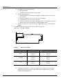
CS 2100 User Guide Notice Congratulations on your purchase of the CS 2100. Thank you for your confidence in our products and we will do all in our power to ensure your complete satisfaction. The User Guide for the CS 2100 includes information on the usage of the equipment. We recommend that you thoroughly familiarize yourself with this Guide in order to make the most effective use of your system. . WARNING: We recommend that you consult the “Safety, Regulatory and Technical Specification User Guide” before using the CS 2100. No part of this Guide may be reproduced without the express permission of Carestream Health, Inc. U.S. Federal law restricts this equipment to sale by or on the order of a dentist or physician. This document is originally written in English. Manual Name: CS 2100 User Guide Part Number: SM759 Revision Number: 01 Print Date: 2012-02 CS 2100 complies with Directive 93/42/EEC relating to medical equipment. 0086 Manufacturer Care stream Hea lth, Inc. 150 Verona Street Roche ster, NY 1 4 60 8, USA Authorized Representative in the European Community EC REP TROPHY 4, Rue F. Pelloutier, Croissy-Beaubourg 77435 Marne la Vallée Cedex 2, France Contents 1—About This Guide Conventions in this Guide . . . . . . . . . . . . . . . . . . . . . . . . . . . . . . . . . . . . . . . . . . . . . . . . . . . . . . . . . . . . . . . . . . . . . . . 1–1 2—CS 2100 SYSTEM OVERVIEW General Overview . . . . . . . . . . . . . . . . . . . . . . . . . . . . . . . . . . . . . . . . . . . . . . . . . . . . . . . . . . . . . . . . . . . . . . . . . . . . . 2–1 CS 2100 Unit Configurations . . . . . . . . . . . . . . . . . . . . . . . . . . . . . . . . . . . . . . . . . . . . . . . . . . . . . . . . . . . . . . . . . . . . 2–4 Control Timer Unit . . . . . . . . . . . . . . . . . . . . . . . . . . . . . . . . . . . . . . . . . . . . . . . . . . . . . . . . . . . . . . . . . . . . . . . . . 2–9 3—CS 2100 RADIOLOGY PROCESS Positioning. . . . . . . . . . . . . . . . . . . . . . . . . . . . . . . . . . . . . . . . . . . . . . . . . . . . . . . . . . . . . . . . . . . . . . . . . . . . . . . . . . . 3–1 Positioning the Patient . . . . . . . . . . . . . . . . . . . . . . . . . . . . . . . . . . . . . . . . . . . . . . . . . . . . . . . . . . . . . . . . . . . . . . 3–1 Positioning the X-Ray Generator . . . . . . . . . . . . . . . . . . . . . . . . . . . . . . . . . . . . . . . . . . . . . . . . . . . . . . . . . . . . . . 3–1 Paralleling technique . . . . . . . . . . . . . . . . . . . . . . . . . . . . . . . . . . . . . . . . . . . . . . . . . . . . . . . . . . . . . . . . . . . . 3–1 Bisecting technique . . . . . . . . . . . . . . . . . . . . . . . . . . . . . . . . . . . . . . . . . . . . . . . . . . . . . . . . . . . . . . . . . . . . . 3–2 Positioning the Imaging Receptor . . . . . . . . . . . . . . . . . . . . . . . . . . . . . . . . . . . . . . . . . . . . . . . . . . . . . . . . . . . . . 3–2 Exposure . . . . . . . . . . . . . . . . . . . . . . . . . . . . . . . . . . . . . . . . . . . . . . . . . . . . . . . . . . . . . . . . . . . . . . . . . . . . . . . . . . . . 3–2 Exposure Parameters . . . . . . . . . . . . . . . . . . . . . . . . . . . . . . . . . . . . . . . . . . . . . . . . . . . . . . . . . . . . . . . . . . . . . . . 3–2 Exposure Times . . . . . . . . . . . . . . . . . . . . . . . . . . . . . . . . . . . . . . . . . . . . . . . . . . . . . . . . . . . . . . . . . . . . . . . . . . . 3–3 Exposure Times for KODAK Film . . . . . . . . . . . . . . . . . . . . . . . . . . . . . . . . . . . . . . . . . . . . . . . . . . . . . . . . . 3–3 Exposure Times for Phosphor Plates . . . . . . . . . . . . . . . . . . . . . . . . . . . . . . . . . . . . . . . . . . . . . . . . . . . . . . . . 3–3 Exposure Times for Digital Sensors. . . . . . . . . . . . . . . . . . . . . . . . . . . . . . . . . . . . . . . . . . . . . . . . . . . . . . . . . 3–4 Emitted Doses. . . . . . . . . . . . . . . . . . . . . . . . . . . . . . . . . . . . . . . . . . . . . . . . . . . . . . . . . . . . . . . . . . . . . . . . . . . . . 3–5 Film Processing . . . . . . . . . . . . . . . . . . . . . . . . . . . . . . . . . . . . . . . . . . . . . . . . . . . . . . . . . . . . . . . . . . . . . . . . . . . 3–6 4—ACQUIRING AN IMAGE Preparing for Image Acquisition . . . . . . . . . . . . . . . . . . . . . . . . . . . . . . . . . . . . . . . . . . . . . . . . . . . . . . . . . . . . . . . . . . 4–1 Launching the X-Ray . . . . . . . . . . . . . . . . . . . . . . . . . . . . . . . . . . . . . . . . . . . . . . . . . . . . . . . . . . . . . . . . . . . . . . . . . . 4–2 5—USER MODE Parameters . . . . . . . . . . . . . . . . . . . . . . . . . . . . . . . . . . . . . . . . . . . . . . . . . . . . . . . . . . . . . . . . . . . . . . . . . . . . . . . . . . . 5–1 Entering the User Mode . . . . . . . . . . . . . . . . . . . . . . . . . . . . . . . . . . . . . . . . . . . . . . . . . . . . . . . . . . . . . . . . . . . . . . . . 5–1 Modifying Parameters . . . . . . . . . . . . . . . . . . . . . . . . . . . . . . . . . . . . . . . . . . . . . . . . . . . . . . . . . . . . . . . . . . . . . . . . . . 5–1 Exiting the User Mode . . . . . . . . . . . . . . . . . . . . . . . . . . . . . . . . . . . . . . . . . . . . . . . . . . . . . . . . . . . . . . . . . . . . . . . . . 5–2 Performing a Tube Seasoning . . . . . . . . . . . . . . . . . . . . . . . . . . . . . . . . . . . . . . . . . . . . . . . . . . . . . . . . . . . . . . . . . . . . 5–2 6—TROUBLESHOOTING Quick Troubleshooting . . . . . . . . . . . . . . . . . . . . . . . . . . . . . . . . . . . . . . . . . . . . . . . . . . . . . . . . . . . . . . . . . . . . . . . . . 6–1 Information Messages . . . . . . . . . . . . . . . . . . . . . . . . . . . . . . . . . . . . . . . . . . . . . . . . . . . . . . . . . . . . . . . . . . . . . . . . . . 6–3 Error Messages . . . . . . . . . . . . . . . . . . . . . . . . . . . . . . . . . . . . . . . . . . . . . . . . . . . . . . . . . . . . . . . . . . . . . . . . . . . . . . . 6–4 7—MAINTENANCE Quarterly . . . . . . . . . . . . . . . . . . . . . . . . . . . . . . . . . . . . . . . . . . . . . . . . . . . . . . . . . . . . . . . . . . . . . . . . . . . . . . . . . . . . 7–1 Generator . . . . . . . . . . . . . . . . . . . . . . . . . . . . . . . . . . . . . . . . . . . . . . . . . . . . . . . . . . . . . . . . . . . . . . . . . . . . . . . . 7–1 Mechanical support. . . . . . . . . . . . . . . . . . . . . . . . . . . . . . . . . . . . . . . . . . . . . . . . . . . . . . . . . . . . . . . . . . . . . . . . . 7–1 CS 2100 User Guide (SM759)_Ed01 1 Contents Control timer unit and electrical installation. . . . . . . . . . . . . . . . . . . . . . . . . . . . . . . . . . . . . . . . . . . . . . . . . . . . . .7–1 Operation. . . . . . . . . . . . . . . . . . . . . . . . . . . . . . . . . . . . . . . . . . . . . . . . . . . . . . . . . . . . . . . . . . . . . . . . . . . . . . . . .7–1 Control timer unit self-test . . . . . . . . . . . . . . . . . . . . . . . . . . . . . . . . . . . . . . . . . . . . . . . . . . . . . . . . . . . . . . . . . . .7–1 Annually . . . . . . . . . . . . . . . . . . . . . . . . . . . . . . . . . . . . . . . . . . . . . . . . . . . . . . . . . . . . . . . . . . . . . . . . . . . . . . . . . . . .7–2 Cleaning and Disinfecting the CS 2100 . . . . . . . . . . . . . . . . . . . . . . . . . . . . . . . . . . . . . . . . . . . . . . . . . . . . . . . . . . . .7–2 2 Chapter 1 About This Guide Conventions in this Guide The following special messages emphasize information or indicate potential risk to personnel or equipment: WARNING Warns you to avoid injury to yourself or others by following the safety instructions precisely. CAUTION Alerts you to a condition that might cause serious damage. IMPORTANT Alerts you to a condition that might cause problems. NOTE Emphasizes important information. TIP Provides extra information and hints. WARNING Exposure to ionizing radiation CS 2100 User Guide (SM759)_Ed01 1–1 Conventions in this Guide 1–2 About This Guide Chapter 2 CS 2100 SYSTEM OVERVIEW The CS 2100 is compliant with the requirements of the EEC and international medical standards. The CS 2100 unit has been designed to produce high-quality intraoral radiographies that: Reveal maximum details with the minimum dose to the patient. Show teeth and anatomic structures accurately with a minimum of distortion or magnification. Have optimal density and contrast to maximize their use for the detection of dental diseases. The CS 2100 uses a high-frequency technology that allows: Reduced X-ray doses for patients because the CS 2100 unit emits fewer soft rays absorbed by patients which are not used during image creation. Shorter exposure times which reduce the risk of motion blurr during exposure The CS 2100 is equipped with a thermal safety system that prevents the generator from overheating in case of intensive use. This prohibits any exposure as long as the generator has not cooled down. The I01 error message appears on the display and an audible beep is heard during the unit cooling period. The beep stops when the cooling period is over. To obtain high-quality intraoral radiography with maximum details, you must be very careful when performing the three steps of the radiography process: Positioning the patient, the X-ray generator, and the imaging system Setting the exposure parameters according to the imaging receptor used (films, phosphor plates or sensors) Processing the film (if a conventional film is used) General Overview The CS 2100 unit is composed of the following functional components A high-frequency X-ray generator which includes: A transformer and associated electronics, and an oil-bathed X-ray tube A beam-limiting device with the following characteristics: - A radiation diameter of 6 cm (2.36 in.) - A distance from the X-ray tube focal spot to skin of 20 cm (8 in.). An angle scale and a handle to facilitate positioning. CS 2100 User Guide (SM759)_Ed01 2–1 General Overview A wall framework which contains the: Main powerboard ON/OFF switch which contains a built-in LED. A control timer unit which: Performs exposure time selection and displays parameters (exposure time and emitted dose). Performs a microprocessor self-test at every unit activation. Displays alarms in case of incorrect operation. Includes two exposure time modes. The digital mode corresponds to the range of shortest exposure times that fit those needed for digital sensors. An extension arm and a scissor arm which is equipped with springs that ensure arm stability. The following figure illustrates the extension arm and the scissor arm. Figure 2–1 CS 2100 - Side View R A Table 2–1 2–2 Extension arm types Extension R Span A Short 47.0 cm (18.5 in.) 170.0 cm Standard 64.8 cm (25.5 in.) 188.0 cm (74 in.) Long 82.5 cm (32.5 in.) 205.0 cm (80.69 in.) (67 in.) A rectangular collimator. Its various sizes adapt to films, phosphor plates and RVG sensors. It is recommended to use such a collimator if possible, in order to limit the radiation absorbed by patients. CS 2100 SYSTEM OVERVIEW General Overview The CS 2100 unit is also composed of a remote exposure switch which is an optional accessory. The following CS 2100 unit configurations are provided: Standard wall-mounted unit Ceiling-mounted unit. The following mounting options are provided: Floor column base Mobile base NOTE These options must be used with a standard wall-mounted unit. CS 2100 User Guide (SM759)_Ed01 2–3 CS 2100 Unit Configurations CS 2100 Unit Configurations Figure 2–2 Standard Wall-Mounted Unit 7 8 2 4 2–4 5 1 3 6 1 High frequency X-ray generator 2 Wall framework 3 Separate control timer unit 4 X-ray exposure button 5 Scissor arm 6 Rectangular collimator 7 ON/OFF switch with built-in LED 8 Extension arm CS 2100 SYSTEM OVERVIEW CS 2100 Unit Configurations Figure 2–3 CS 2100 Unit with Separate Exposure Switch 4 7 8 2 5 1 3 6 NOTE This configuration is an optional configuration 1 High frequency X-ray generator 2 Wall framework 3 Control timer unit 4 X-ray exposure switch with X-ray exposure button 5 Scissor arm 6 Rectangular collimator 7 ON/OFF switch with built-in LED 8 Extension arm CS 2100 User Guide (SM759)_Ed01 2–5 CS 2100 Unit Configurations Figure 2–4 Ceiling-Mounted Unit 2 5 8 3 7 1 4 6 2–6 1 High frequency X-ray generator 2 Ceiling mounted unit containing the main powerboard 3 Control timer unit 4 X-ray exposure switch 5 Scissor arm 6 Rectangular collimator 7 ON/OFF switch with built-in LED 8 Extension arm CS 2100 SYSTEM OVERVIEW CS 2100 Unit Configurations Figure 2–5 Unit Mounted on Floor Column 5 8 1 3 7 6 9 4 2 1 High frequency X-ray generator 2 Floor column containing the main powerboard 3 Control timer unit 4 X-ray exposure switch with X-ray exposure button 5 Scissor arm 6 Rectangular collimator 7 ON/OFF switch with built-in LED 8 Extension arm 9 Raiser CS 2100 User Guide (SM759)_Ed01 2–7 CS 2100 Unit Configurations Figure 2–6 Unit Mounted on Mobile Base 5 3 1 7 4 8 6 2 9 2–8 1 High frequency X-ray generator 2 Mobile stand containing the main powerboard 3 Control timer unit 4 X-ray exposure switch with X-ray exposure button 5 Scissor arm 6 Rectangular collimator 7 ON/OFF switch with LED 8 Handle 9 Foot brake CS 2100 SYSTEM OVERVIEW CS 2100 Unit Configurations Control Timer Unit 1 3 S mGy 60 kV - 7 mA + 8 _ 7 digital - 2 push 9 6 5 4 1 Warning: Ionizing radiation 2 Exposure time - emitted dose indicator 3 Display 4 X-ray exposure button 5 X-ray emission control light 6 Ready state 7 Exposure time selector: - Lit: shortest exposure times for digital sensors - OFF: longest exposure times for films and phosphor plates 8 Warning 9 Selection knob: - Press and hold the knob to activate the exposure time selector. - Rotate the knob to select the exposure time. CS 2100 User Guide (SM759)_Ed01 2–9 CS 2100 Unit Configurations 2–10 CS 2100 SYSTEM OVERVIEW Chapter 3 CS 2100 RADIOLOGY PROCESS Positioning Positioning the Patient To position the patient, you must have: The patient sit with the vertical sagittal plane. The patient’s head positioned as follows: For upper maxillary radiography, the Frankfort plane (nose-ear plane) must be horizontal. For lower maxillary radiography, the occlusal plane must be horizontal. 90° Positioning the X-Ray Generator The scissor arm allows you to accurately position the generator for any type of exposure. The beam-limiting device maintains a distance of at least 20 cm (8 in.) between the focal spot and the skin, which allows you to use either the paralleling or the bisecting technique. Paralleling technique The positioning tool used in the paralleling technique allows you to align the beam and the imaging receptor. An appropriate collimator reduces the dosage by limiting the surface exposure. CS 2100 User Guide (SM759)_Ed01 3–1 Exposure Bisecting technique When using the bisecting technique, do not use a rectangular collimator. This limits the risk of X-ray beam and image receptor misalignment. 90° Positioning the Imaging Receptor Using the CS 2100, you may create an X-ray image on one of the following imaging receptors: Conventional silver halide films, such as KODAK dental films. Digital sensors such as RVG sensors. Phosphor plate such as CS Imaging plates. Placing the receptor correctly is critical. Check your own dental radiography manual for information on how to place the imaging receptor correctly. If you do not position the film or the sensor correctly, this results in errors on the radiography, such as distorted teeth and roots, elongation, magnification, and/or overlapping contacts. The paralleling technique generally reduces the risk of such errors. However, if you do not position the system correctly, angulation errors can occur (angulation of the receptor to the tooth itself). If the beam exit pattern is not aligned with the imaging receptor, then part of the radiography will not be exposed to radiation and the final radiography will have some clear (unexposed) areas. This defect is called “cone cuts". The imaging receptor is marked to indicate the tube side. If the orientation is not correct, the resulting radiography is lighter and may show artifacts, such as foil pattern or sensor cable. Exposure Exposure Parameters Since each receptor (film, phosphor plate or digital sensor) has its own sensitivity to X-ray radiation. the sensor choice impacts the exposure parameters. For instance, the sensitivity class for conventional dental films is characterized with the letter D, E, or F where F is more sensitive than E, and E more sensitive than D. Consequently, the required dose for the correct exposure goes down as sensitivity increases. Due to the different sensitivity of the digital sensors, you also need to adjust the exposure parameters to the used sensor type (film or digital equipment). The CS 2100 allows you to select the exposure times. The exposure times indicated in Tables 3-1 to 3-4 meet the manufacturer’s recommendations. Depending on the used sensor type, you can change the mode by pressing and holding the selection knob for at least three seconds. To set the exposure times, see the Preparing for Image Acquisition section. 3–2 CS 2100 RADIOLOGY PROCESS Exposure Exposure Times Exposure Times for KODAK Film The indicated exposure times are given as a guideline. Table 3–1 Exposure Times for KODAK Film 60 kV - 7 mA - Cone 20 cm (8 in.) Maxillary Mandibular Bitewing Occlusal Anterior Premolar Molar Anterior Premolar Molar Anterior Posterior ULTRASPEED (D) Child 0.250 0.320 0.400 0.200 0.250 0.250 0.200 0.250 0.500 Adult 0.400 0.500 0.630 0.320 0.400 0.400 0.320 0.400 0.630 INSIGHT Child (F) Adult 0.100 0.125 0.160 0.080 0.100 0.100 0.080 0.100 0.200 0.160 0.200 0.250 0.125 0.160 0.160 0.125 0.160 0.250 Child 0.250 0.320 0.400 0.200 0.250 0.250 0.200 0.250 0.500 Adult 0.400 0.500 0.630 0.320 0.400 0.400 0.320 0.400 0.630 Child 0.125 0.160 0.200 0.100 0.100 0.125 0.100 0.125 0.200 Adult 0.200 0.250 0.250 0.160 0.160 0.200 0.160 0.200 0.320 D-SPEED E-SPEED Exposure Times for Phosphor Plates The indicated exposure times are given as a guideline. Table 3–2 Exposure Times for Phosphor Plates 60 kV - 7 mA - Cone 20 cm (8 in.) Maxillary Mandibular Bitewing Occlusal Anterior Premolar Molar Anterior Premolar Molar Anterior Posterior Child 0.250 0.320 0.400 0.200 0.250 0.250 0.200 0.250 0.500 Adult 0.400 0.500 0.630 0.320 0.400 0.400 0.320 0.400 0.630 Child 0.160 0.200 0.250 0.125 0.160 0.160 0.125 0.160 0.320 Adult 0.250 0.320 0.400 0.200 0.250 0.250 0.200 0.250 0.500 CR7400 CS 7600 CS 2100 User Guide (SM759)_Ed01 3–3 Exposure Exposure Times for Digital Sensors The indicated exposure times are given as a guideline. Table 3–3 Exposure Times for Digital Sensors 60 kV - 7 mA - Cone 20 cm (8 in.) Maxillary Mandibular Bitewing Occlusal Anterior Premolar Molar Anterior Premolar Molar Anterior Posterior RVG 6500 (size 1&2) Child 0.080 0.100 0.125 0.063 0.080 0.080 0.063 0.080 0.125 Adult 0.125 0.160 0.200 0.125 0.160 0.160 0.100 0.125 0.200 RVG 6500 (size 0) Child 0.040 0.050 0.063 0.032 0.040 0.040 0.032 0.040 0.080 Adult 0.063 0.080 0.100 0.050 0.063 0.063 0.050 0.063 0.100 RVG 6100 (size 1& 2) Child 0.080 0.100 0.125 0.063 0.080 0.080 0.063 0.080 0.125 Adult 0.125 0.160 0.200 0.125 0.160 0.160 0.100 0.125 0.200 RVG 6100 (size 0) Child 0.040 0.050 0.063 0.032 0.040 0.040 0.032 0.040 0.080 Adult 0.063 0.080 0.100 0.050 0.063 0.063 0.050 0.063 0.100 Child 0.100 0.125 0.160 0.080 0.080 0.100 0.080 0.100 0.160 Adult 0.160 0.160 0.200 0.125 0.125 0.160 0.125 0.160 0.250 Child 0.080 0.100 0.125 0.063 0.080 0.080 0.063 0.080 0.125 Adult 0.125 0.160 0.200 0.125 0.160 0.160 0.100 0.125 0.200 Child 0.100 0.125 0.160 0.080 0.080 0.100 0.080 0.100 0.160 Adult 0.160 0.160 0.200 0.125 0.125 0.160 0.125 0.160 0.250 TROPHY RVG Ultimate Child 0.080 0.100 0.125 0.063 0.080 0.080 0.063 0.080 0.125 Adult 0.125 0.160 0.200 0.100 0.100 0.125 0.100 0.125 0.200 TROPHY RVG Access Child 0.100 0.125 0.160 0.080 0.080 0.100 0.080 0.100 0.160 Adult 0.160 0.200 0.200 0.125 0.125 0.160 0.125 0.160 0.250 TROPHY Child RVG Reference High Resolution Adult mode 0.080 0.100 0.125 0.063 0.063 0.080 0.063 0.080 0.125 0.125 0.160 0.160 0.100 0.100 0.125 0.100 0.125 0.200 TROPHY RVG Reference High Sensitive mode Child 0.020 0.025 0.032 0.016 0.020 0.020 0.016 0.020 0.040 Adult 0.032 0.040 0.050 0.025 0.032 0.032 0.025 0.032 0.050 TROPHY Child RVGui High Resolution mode Adult 0.080 0.100 0.125 0.063 0.063 0.080 0.063 0.080 0.125 0.125 0.160 0.160 0.100 0.100 0.125 0.100 0.125 0.200 TROPHY Child RVGui High Sensitivite Adult mode 0.020 0.025 0.032 0.016 0.020 0.020 0.016 0.020 0.040 0.032 0.040 0.050 0.025 0.032 0.032 0.025 0.032 0.050 Child 0.040 0.050 0.063 0.032 0.040 0.040 0.032 0.040 0.080 Adult 0.063 0.080 0.100 0.050 0.063 0.063 0.050 0.063 0.100 RVG 5100 RVG 6000 RVG 5000 TROPHY RVG THD 3–4 CS 2100 RADIOLOGY PROCESS Exposure The following table is a template that you may fill in according to your specific conditions. Table 3–4 Customized Table for Exposure Times 60 kV - 7 mA - Cone 20 cm (8 in.) Maxillary Mandibular Bitewing Occlusal Anterior Premolar Molar Anterior Premolar Molar Anterior Posterior Child Adult Child Adult Emitted Doses To obtain the dose in mGy.cm2, multiply the values listed in Table 3-5 by the exposure surface. The exposure surface depends on the used collimator type as indicated in Table 3-6. Table 3–5 Measured Dose at the End of the 20 cm (8 in.) Cone 60 kV - 7 mA t (s) D (mGy) t (s) D (mGy) 0.010 0.06 0.200 1.22 0.013 0.08 0.250 1.52 0.016 0.10 0.320 1.95 0.020 0.12 0.400 2.44 0.025 0.15 0.500 3.05 0.032 0.19 0.630 3.84 0.040 0.24 0.800 4.87 0.050 0.30 1.000 6.09 0.063 0.38 1.250 7.61 0.080 0.49 1.600 9.74 0.100 0.61 2.000 12.18 0.125 0.76 2.500 15.23 0.160 0.97 NOTE Dose accuracy: +/- 30% (mGy) CS 2100 User Guide (SM759)_Ed01 3–5 Exposure Table 3–6 Exposure Surface versus Collimator Type Collimator type Format (cm) Used with digital sensor Used with films or phosphor plates (cm) Exposure surface (cm2) A 1.9 x 2.4 Size 0 - 4.6 B 2.3 x 3.5 Size 1 Size 0: 2.2 x 3.5 8.3 C 3.1 x 3.9 Size 2 Size 1: 2.4 x 4.0 Size 2: 3.1 x 4.1 12.1 Standard cone 6.0 cm diameter - Size 3: 2.7 x 5.4 Size 4: 5.7 x 7.6 28.3 Film Processing When using conventional films, you must process the film according to the manufacturer’s instructions. Process the film under safelight conditions manually or using an automatic processor. If you use an automatic processor, see the processor’s manual. Check that the processor maintenance is performed regularly. If you process the film manually, follow precisely the manufacturer’s recommendations for solution preparation, processing time, and solution temperature for both the developer and the fixer baths. Any deviation from the manufacturer’s recommendations (such as a solution that would be too concentrated or diluted, too hot or cold, or if the film processing duration is incorrect) will impact the final radiography quality. Before archiving, do not forget to wash the film correctly and to dry it in a clean place. 3–6 CS 2100 RADIOLOGY PROCESS Chapter 4 ACQUIRING AN IMAGE This chapter describes the various tasks that you must perform for image acquisition. To acquire an image, you can use conventional films or digital receptors. If necessary, for example after a long inactivity period of the CS 2100 system, we recommend to start with the tube seasoning procedure. For more information, see the Tube Seasoning Procedure. Preparing for Image Acquisition To prepare for image acquisition, follow these steps: 1. Switch ON the unit. The green ON/OFF button indicator lights up. When you switch ON the unit, a self-test starts automatically. It checks the display. When the test is completed, a short beep sounds. If an error occurs, an error code appears. For error messages, see the Troubleshooting section. + _ 2. Select the exposure mode (film or digital) by pressing and holding for at least three seconds until the correct mode is displayed. The indicator lights up if you use a digital sensor wherreas it is OFF if you use a film. NOTE Depending on your local regulations, you may disable this function. See the User Mode section. + _ 3. Turn to select the exposure time. For more information on exposure times, see Tables 3-1, 3-2, 3-3, and 3-4. NOTE - Exposure time ranging from 0.05 to 1.25 s (exposure selector off): if you use a film or a storage phosphor plate. - Exposure time ranging from 0.010 to 0.063 s (exposure selector lit): if you use a digital sensor. The unit is now ready for acquisition. IMPORTANT The operator must instruct the patient to refrain from moving during the entire exposure. CS 2100 User Guide (SM759)_Ed01 4–1 Launching the X-Ray Launching the X-Ray To launch the X-ray, follow these steps: WARNING Be careful not to be exposed to ionizing radiation 1. Press from the control timer unit or from the X-ray exposure switch. The X-ray emission indicator lights up and a beep is heard. 2. Keep pressing until the X-ray emission indicator is OFF and the beep stops. During the X-ray emission, the exposure time counts off on the display. CAUTION If you release the button before the end of the X-ray, a manipulator alarm (E01) is enabled. This indicates that the X-ray emission was aborted prematurely. There is an underexposure risk. Depending on the remaining time, you can decide to process the image or start a new image acquisition. + _ To stop the alarm, press on from the control timer unit. When the acquisition is completed, the emitted dose is displayed in mGy. The “mGy” indicator lights up. For information on the emitted doses based on the exposure times, see Table 3-5. The latest parameter settings are kept until a new image acquisition is performed. + _ 3. Press on 4–2 ACQUIRING AN IMAGE shortly to change from mGy to exposure time display. Chapter 5 USER MODE This chapter describes the various settings that you can select for the different pre-set modes. The user mode also allows you to validate specific local requirements for some countries. Parameters Table 5–1 Parameters Available through the User Mode Number Parameters Choice P 01 Digital receptor ON/OFF (needed for correct emitted dose display) P 05 Tube seasoning procedure Switches from OFF to ON P 06 Show mode ON: Disables the X-ray emission OFF (default value): Enables the X-ray emission Entering the User Mode To enter the user mode, follow these steps: 1. Switch ON the unit. The self-test is enabled. While the self-test is in progress, the software information (for example, F718 2.1) is displayed. + _ 2. Once F718 2.1 is displayed, press shortly on from the control timer unit. You access the menu, when "USER" is displayed. The display intermittently shows the first parameter (P 01) and its setting (for example, "ON"). + _ 3. To switch from one parameter to the other, turn in any direction. Modifying Parameters To modify parameters, follow these steps: + _ 1. Turn to select the parameter to modify. + _ 2. Press on until "EDIT" is displayed and a beep is heard. The parameter value starts blinking. CS 2100 User Guide (SM759)_Ed01 5–1 Exiting the User Mode + _ 3. Turn to change the parameter value. + _ 4. To validate, press and hold beep is heard. for at least 3 seconds until "COPY" is displayed and a + _ 5. To keep the initial value, press on the parameter/program mode. shortly. "ABOR" is displayed. The system returns to Exiting the User Mode + _ To exit the user mode, press on shortly. “QUIT” is displayed until the system returns to the operational mode. The self-test continues until it is completed. Performing a Tube Seasoning This procedure allows for a progressive warm-up of the X-ray tube. It must be performed at unit installation and when replacing the tube head. It can also be performed when needed, for instance after a long period of equipment inactivity. It lasts around three minutes. To perform a tube seasoning, follow these steps: 1 Go to the User Mode menu and change parameter P 05 from OFF to ON. The self-test continues. After the self-test is completed, I 02 is displayed. This message means that the seasoning process must be started. + _ 2 Press on . The display blinks,. The sequence step number and the required exposure settings (kV, time) are displayed alternatively. 3 Stand behind the generator. 4. Launch an X-ray. WARNING Be careful not to be exposed to ionizing radiation When the exposure is completed, the display blinks. The cooling error code (I 01) and the remaining time required before the next step are displayed alternatively. When the cooling cycle is completed, the display blinks. The next step number and its exposure settings are displayed alternatively. 5–2 USER MODE Performing a Tube Seasoning 5 Repeat steps 3 and 4 until the end of the sequence. Your system is ready. CS 2100 User Guide (SM759)_Ed01 5–3 Performing a Tube Seasoning 5–4 USER MODE Chapter 6 TROUBLESHOOTING Occasionally, malfunctions can occur during use in the event of an incorrect action or failure. The quick troubleshooting, the Information “Ixx” and Error message “Exx” guide you through the actions you need to take to correct the malfunction. IMPORTANT If the malfunction persists or more serious conditions occur, contact your representative and stop the equipment. When you call your representative, you must have the following information ready: Model Number: CS 2100 Serial Number (on the labels) Error Code Number: Exx. Quick Troubleshooting Quick troubleshooting guides you through the actions you need to take to correct the malfunctions. The following table lists the malfunctions and the actions to take. Malfunction Nothing lights up Possible Cause Action The unit is disconnected. Connect the unit. Fuse F1 burnt out or is defective. Change the fuse. The circuit breaker is OFF. Turn ON the circuit breaker Control unit doesn't light up. The control unit is disconnected. Connect the control unit. Fuse F1 burnt out or is defective. Change the fuse. The control unit is defective Call your representative. No X-ray emission The generator is cooling Wait until the I01message is no longer displayed. The radiology control key is Call your representative. defective. The X-ray emission works, but The generator is not the exposure is too light or positioned correctly. completely white. Adjust the generator position The exposure time is too short. Increase the exposure time. The development time is too short. Increase the development time (See the manufacturer’s instructions). CS 2100 User Guide (SM759)_Ed01 6–1 Quick Troubleshooting Malfunction Possible Cause The developer is too cold. Action Heat the developer The developer is too old or Replace with a new developer diluted. The exposure time mode is Check your exposure settings (See the not correctly selected exposure procedure). The receptor is not correctly positioned. Reposition the receptor. The unit is not correctly installed. Call your representative. The X-ray emission works but The exposure time is too exposure is too dark. long. Reduce the exposure time. The development time is too long. Reduce the development time (See the manufacturer’s instructions). The developer is too hot. Cool the developer The developer is too concentrated. Adjust the concentration or change developer. The exposure time mode is Check your exposure settings (See the not correctly selected. exposure procedure). 6–2 TROUBLESHOOTING Information Messages Information Messages An information “I” error code with a message appears on the display. The following table lists the information messages and the actions to take. Table 1 Information Messages Information Code I 01 Possible Cause Cooling cycle: this message can appear during intensive use period. Action Do not switch OFF the equipment. The information message disappears as soon as the system reaches a satisfactory temperature. IMPORTANT If you switch OFF the system, the microprocessor does not calculate the cooling time. For safety reasons, it considers that the system has not gone through the cooling cycle. I 02 Request for X-ray tube seasoning. See the User Mode section. CS 2100 User Guide (SM759)_Ed01 6–3 Error Messages Error Messages The following table lists the error messages and the actions to take. Table 2 Error Messages Error Message Possible Cause Action E01 + audible The radiography control button was released Quickly press on the selection knob before the exposure end. The display indicates to stop the alarm. alarm the remaining exposure time. Based on this time, you must decide whether to develop the film or make another exposure). E02 The radiography control was enabled while the unit was being powered ON. E03-E04 Exposure time control problems E10 to E18 kV voltage error E20 to E24 Switch OFF the unit, then restart it. If the problem persists, contact your Problem with voltage to the main power supply representative and stop using the equipment. or to the chemical capacitor E30 6–4 Filament voltage error E40 to E46 System error (problems with the power board microprocessor) E50 to E54 Problem with the IC bus, the connection between the control panel and the power board. TROUBLESHOOTING Chapter 7 MAINTENANCE This chapter describes the maintenance tasks you must perform for your CS 2100. Quarterly Generator Check that: The certification label is legible. No oil leaks. Mechanical support Check that: The wall framework is securely attached to the wall. All labels are legible. The scissor arm is stable in all positions. Control timer unit and electrical installation Check that: The symbols are legible. The control timer unit and the power supply cables are in good condition. The ground is installed correctly. The X-ray exposure button returns to its initial position after use. Operation WARNING Be careful not to be exposed to ionizing radiation Check that: The audible signal is heard and the X-ray emission indicator is visible when you launch an X-ray (exposure time: 0.1 sec). The “E01” message is displayed when you launch an X-ray (exposure time:1.0 sec) and you release the control button before the exposure end. Control timer unit self-test To enable the self-test, you must switch ON the CS 2100 system. The self-test starts with a simultaneous display and alarm light test. CS 2100 User Guide (SM759)_Ed01 7–1 Annually Then, the system test starts. After the test is completed (indicated by a short beep), the firmware version and the total number of exposures (divided by 10) performed by the unit since first installation are displayed. If the test fails, an error message is displayed. IMPORTANT If a check result is not satisfactory, stop using the equipment and contact your representative. Annually We recommend that a general inspection of the unit be carried out by an authorized service technician provided by your representative. Cleaning and Disinfecting the CS 2100 IMPORTANT You must first clean the system before disinfection. To clean the system, follow these steps: 1 Clean the outside of the equipment with a damp paper towel or a soft cloth using an alcohol-based, non-corrosive cleaner. 2 Wipe off surfaces with either an intermediate disinfectant or a low-level disinfectant. CAUTION Liquids must not drip into the equipment. Do not spray cleaner or disinfectant directly on the equipment. Follow the manufacturer’s safety recommendations when using a cleaner or a disinfectant. 7–2 MAINTENANCE