1
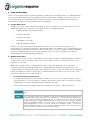
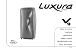
Demo Node User Guide
Revision v1.0 April 2014
1 WHAT IS A DEMO NODE? ............................................................................................................................................. 1 a Backlit Dimmable LED panel .................................................................................................................................. 2 b Sensor Node ............................................................................................................................................................. 2 c (Underside panel) Magnetic Contacts for Surface Mounting ........................................................................... 2 d USB Connector ......................................................................................................................................................... 2 e RJ45 Connector ....................................................................................................................................................... 2 f Mini-USB Power Inlet Connector & Battery Charging Status LEDs ...................................................................... 2 g LED Indicators ........................................................................................................................................................... 2 h ON/OFF Switch ......................................................................................................................................................... 2 2 USING THE DEMO NODE ............................................................................................................................................... 3 a A Single Demo Node .............................................................................................................................................. 3 b Multiple Demo Nodes ............................................................................................................................................. 3 i
Demonstrate Infrared Communications .......................................................................................................... 3
ii
Site Application Test ............................................................................................................................................ 4
iii
Demonstrate a Relay of Optimised Settings .................................................................................................... 4
Please note that interaction with the Demo Node is performed using the Organic Response Smart Phone App,
which has been downloaded onto an iPhone/iPad/iPod Touch fitted with an infrared dongle. For more
information on downloading the remote app and/or acquiring the dongle please visit
organicresponse.com.au/marketing-resources
1
WHAT IS A DEMO NODE?
A Demo Node is a fully functioning portable Organic Response-Enabled luminaire fitted with a dimmable LED
light panel and Sensor Node. Two or more Demo Nodes allow for a full demonstration of the Organic Response
control system and its unique form of Distributed Intelligence communication.
A Demo Node kit comprises two Demo Nodes and a charge cable in a protective carry case.
Each Demo Node comprises the following:
•
Dimmable backlit LED panel.
•
Organic Response Sensor Node.
•
Rechargeable battery.
•
USB power outlet.
•
Magnetic contacts (underneath)
Figure 1: Demo Node & Features
a Backlit Dimmable LED panel
Simulates an Organic Response-Enabled light source, with light output controlled by the integrated Senor
Node. The panel may be dimmed to any level between 10% and 100%. The panel is representative of a
luminaire and is not intended for any functional task illumination.
b Sensor Node
Integrated Organic Response Sensor Node. Together with the dimmable LED panel, it operates in exactly
the same way as any Organic Response-Enabled luminaire.
c
(Underside panel) Magnetic Contacts for Surface Mounting
Four magnets are mounted in the base of each Demo Node, enabling attachment to magnetic surfaces
like an existing luminaire frame or ceiling brackets. The magnet faces are polarized to allow two Demo
nodes to attach back to back. Take care to ensure that the magnets have suitable adhesion to a surface,
to avoid them falling on someone who may be underneath.
d
USB Connector
The USB connector supplies 5V power to external devices (e.g. lamps, fans, etc). Once connected to such
an electrical device the Demo Node serves as an Organic Response Enabled power board, which
responds to the occupancy information it receives and turns the power to the external device on or off as
required.
e
RJ45 Connector
Not currently supported by the firmware, but in future will allow connection for data collection.
f
Mini-USB Power Inlet Connector & Battery Charging Status LEDs
This mini-USB connection is used to recharge the Demo Node battery from a USB power source (e.g. laptop
computer). On connection of the USB cable, the top LED will glow red, to indicate that battery charging is
in progress. When the battery is fully charged, the bottom LED glows green. Typically, a fully flat battery will
take about 8 hours to fully recharge. At maximum brightness, the battery will give a run time of
approximately 2 hours.
g
LED Indicators
Once turned ON, the Sensor Node will flash its dome red for 2 seconds to confirm activation. When the
Demo Node is switched on, the top LED indicator glows blue; when the battery is low, the bottom LED glows
orange.
h
ON/OFF Switch
This slide switch turns the Demo Node on or off.
PAGE 2 OF 6
2
USING THE DEMO NODE
A Demo Node is designed to be used as a simulation of a fully functional Organic Response enabled luminaire
when demonstrating Organic Response Lighting Controls. A combination of multiple Demo Nodes with one or
more Organic Response enabled luminaires provides a powerful, compact, portable and easily deployed
demonstration of a fully functioning Organic Response installation.
a
A Single Demo Node
A single Demo Node can powerfully demonstrate to anyone, anywhere, the ease with which a user can
adjust and optimize the performance of an Organic Response Enabled luminaire:
•
Adjusting the light output (DIM+ & DIM-)
•
Setting the Max Light
•
Setting the Dwell Time
•
Changing the Personality
•
Calibrating daylight dimming
Whilst you can effectively perform all optimisation functions on the Demo Nodes, it makes sense to
demonstrate those settings whose impact is immediately visible to the audience (e.g. changing Light Levels
and Dwell Times), rather than settings which are only visible in the context of a large community of Organic
Response enabled luminaires (e.g. Personality settings), or that only respond to significant changes in
ambient light (e.g. daylight dimming calibration)
b
Multiple Demo Nodes
When one or more Demo Nodes, or alternatively another Organic Response Enabled luminaire, is added to
a single Demo Node, the resultant system can be used to demonstrate the communications that occur
between Sensor Nodes.
Note: Care should be taken to avoid placing the demo nodes near significant sources of infrared
interference (including existing light fittings that contain ballasts that may generate signals which can
negatively affect the infrared performance of the Organic Response system. Also ensure that any luminaire
being controlled by the demo node unit does not directly illuminate the demo node sensor node, as this
may interfere with inter-node communications.
i
Demonstrate Infrared Communications
The Infrared Communications demonstration could be done in the context of presenting the system to
a potential client, or to test the range of communication within a specific office environment (e.g. with
a particular floor material, ceiling height and/or luminaire spacing).
A simple demonstration of Organic Response communications can be conducted as follows:
STEP 1
Switch on both Demo Nodes and place them apart from each other on the desk or
table.
STEP 2
Point your Organic Response smartphone remote (with infrared dongle attachment) at
the target Demo Node and select “Test Transmission”. This will cause the target Demo
Node to send out a series of 30 IR signals (2 per second over 15 seconds), which should
be picked up by any neighbouring active Sensor Node, be it a Demo Node or Organic
Response Enabled luminaire. The dome of the receiving Sensor Node will blink red in
acknowledgement of each of the 30 signals it successfully receives. This process
effectively illustrates how two Sensor Nodes communicate with each other without any
need to set-up or commission these communications.
PAGE 3 OF 6
STEP 3
For added effect, take your hand and place it over the transmitting Sensor Node. This
physical barrier will prevent the transmission of IR communications, and you will observe
that the dome of the receiving node will stop flashing. Remove your hand and
communications should continue as normal.
STEP 4
To indicate the limited range of the infrared proximity limited communication, take the
transmitting node and increase the distance between it and the receiving node. As
the distance increases, the likelihood of communication reduces, and you will find that
some signals will not be received. By increasing the distance further, you will observe
the blinking move through intermittent to no blinking at all. Moving closer again to the
other node will resume communications and blinking should again be obvious.
Note: The recommended maximum distance between Sensor Nodes installed in the ceiling is 3m.
ii
Site Application Test
To test the suitability of Organic Response to an existing office space, the Demo Nodes can be
attached to two adjacent luminaires (or alternatively the nearby t-bar ceiling), using the magnetic
contacts on the back of the Demo Node casing.
STEP 1
Repeat the transmission test and count the number of successful communications
between the two nodes. This can be completed in any location, to show both where
communication will occur, as well as where it won’t.
Note: that receipt of 27 or more of the 30 Infrared test signals is indicative of strong and consistent
communication.
iii
Demonstrate a Relay of Optimised Settings
The IR communications can be used to relay the optimised set-points of one OR Enabled luminaire to all
others within communication range. This increases the speed and ease of optimising a site once
installation of the luminaires is completed.
Start by either placing the Demo Nodes apart on a desk/table, or attach them to neighbouring
luminaires on the ceiling.
DIMMING &
MAXLIGHT
For added effect, take your hand and place it over the transmitting Sensor
Node. This physical barrier will prevent the transmission of IR communications,
and you will observe that the dome of the receiving node will stop flashing.
Remove your hand and communications should continue as normal.
DWELL TIME
Using the smartphone app, change the dwell time on one of the Sensor
Nodes. Then, still pointing the remote app at the same Demo Node, press
Relay Max, and confirm that the second Demo Node dome lights up red to
acknowledge receipt of the relayed message.
Note: the dome of the relaying node will flash red for 60 seconds to indicate it is sending the signal. The
dome of any node that receives the signal will remain solid red for a period of 60 seconds, indicating
that it has both received the signal and re-communicated it to it’s neighbours.
If you have any questions or concerns after following all directions in this document, please contact organic
response for further support.
E
[email protected]
Australia
T
+61 3 9486 9823
Europe
T
+31 20 893 4149
PAGE 4 OF 6