1
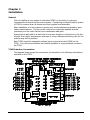
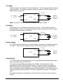
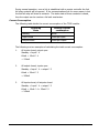
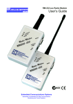
TCM2-4DIO
Telemetry Control Module
User’s Guide
Embedded Communications Systems
Specialists in Embedded RF Data Communications,
Monitoring and Control Systems
Copyright Notice
Copyright
©2002-2003 by Embedded Communications Systems Pty Ltd. All rights reserved.
Under the copyright laws, this manual cannot be reproduced in any form without the
prior written permission of Embedded Communications Systems. No patent liability is
assumed, with respect to the use of the information contained herein.
embeddedcomms TCM2-4DIOTelemetry Control Module User’s Guide
Fourth Edition April 2004 (Covers firmware version 2.00a. Hardware 320-6+)
Disclaimer
This manual has been validated and reviewed for accuracy. The instructions and
descriptions it contains are accurate for the embeddedcomms TCM2-4DIO-433
Telemetry Control Module at the time of this manuals publication. However
succeeding products and manuals are subject to change without notice. Embedded
Communications Systems assumes no liability for damages incurred directly or
indirectly from errors, omissions or discrepancies between the TCM2-4DIO controller
and the manual.
These radio devices may be subject to radio interference and may not function as
intended if interference is present. Systems should be designed to tolerate such
interference.
RF transmission power levels are subject to regulatory approval in countries:
consequently, it is possible that some radio interface functionality is not provided in
your country. This will be detailed in this manual if applicable.
Radio and EMC Regulations
The user of the TCM2-4DIO Telemetry Control Module must satisfy all relevant EMC
and other regulations applicable in the intended country of use.
The radio modules used in the TCM2-4DIO Telemetry Control Modules are type
approved to EN 300 220-3 and EMC conformant to EN 301 493-3.
Problem Reporting and Feedback
To report operational problems, documentation problems, suggested product
enhancements or obtain technical assistance please email technical support at
[email protected]. Please include in all email
correspondence your name, company, controller type, module serial number and
firmware version.
All information supplied to Embedded Communications Systems will be treated in the
strictest of confidence.
User’s Guide
Page ii
About this Manual
How To Use This Manual
In order to obtain the maximum benefit from your TCM2-4DIO product, it is
recommended that you read at least the introduction chapter and the installation &
operation chapter.
Warnings
1. Incorrect termination of the supply lines may result in internal damage to your
TCM2-4DIO module and will void your warranty. To avoid any such issues please
double check all wiring prior to applying power to the module.
2. It is strongly recommended that each TCM2-4DIO module be checked
operationally on the work bench prior to being wired into the final application.
3. To avoid potential accidents during installation and maintenance of remote
controlled equipment, all equipment should be disconnected and electrically
isolated from the TCM2-4DIO module.
4. All equipment connected to the TCM2-4DIO module should be clearly labelled with
a warning indicating that the equipment is subject to automatic operation and may
start without warning.
5. The TCM2-4DIO is not suitable for use in explosive environments or for life critical
applications.
6. The TCM2-4DIO power regulation and battery charging circuit can become
relatively hot during operation. This is normal and as a result good ventilation
should be provided around the power regulation components on the module. Also
contact with the power supply components should be avoided.
Package Contents
The TCM2-4DIO IO Control module is supplied only as an OEM PCB. A serial D9
extension cable is required for connection to a serial terminal program for
configuration.
Printed manuals are not supplied with the IO Controller. Instead the manual is
supplied in electronic form with you order.
Antennas are not provided with the TCM2-4DIO Controller module. Please contact
your supplier for a selection of antennas to use.
User’s Guide
Page iii
Contents:
Chapter 1 Introduction ......................................................................................... 2-1
General .................................................................................................................2-1
The TCM2 – Telemetry Control Module .....................................................................2-1
Features................................................................................................................2-1
Applications...........................................................................................................2-1
Chapter 2 Installation........................................................................................... 2-1
General .................................................................................................................2-1
TCM2 Interface Connections ....................................................................................2-1
Enclosure ..............................................................................................................2-2
RS232 Serial Port ...................................................................................................2-2
Power Supply.........................................................................................................2-2
AC Supply..............................................................................................................2-3
DC Supply .............................................................................................................2-3
Battery Supply .......................................................................................................2-3
Digital Inputs.........................................................................................................2-3
Digital Outputs.......................................................................................................2-4
Indicator LEDs .......................................................................................................2-4
Fail Safe Operation .................................................................................................2-5
Current Consumption..............................................................................................2-6
Chapter 3 Operation ............................................................................................. 3-1
Power Failure – System Power Fault.........................................................................3-1
Event Reporting .....................................................................................................3-1
Chapter 4 TCM2 Configuration ............................................................................. 4-1
General .................................................................................................................4-1
The Serial Interface ................................................................................................4-1
Entering the Configurator........................................................................................4-2
Password Protection ...............................................................................................4-2
Data Encryption .....................................................................................................4-2
Addressing Scheme ................................................................................................4-2
Port Numbering......................................................................................................4-3
Types of Configuration Settings ...............................................................................4-3
Default User Options ..............................................................................................4-4
Default Port Mapping ..............................................................................................4-4
User’s Guide
Introduction iv
Default Port Settings...............................................................................................4-5
General Commands in Detail....................................................................................4-6
User Option Commands ..........................................................................................4-7
Port Mapping Command..........................................................................................4-9
Port Setting Command..........................................................................................4-10
Chapter 5 Product Version Information ............................................................. 5-14
Version Information..............................................................................................5-14
Firmware Version Numbering Scheme.....................................................................5-14
Chapter 6 Modification History........................................................................... 6-15
Hardware ............................................................................................................6-15
Firmware.............................................................................................................6-15
User’s Guide
Introduction v
Chapter 1
Introduction
General
This manual covers the TCM2-4DIO-xxx range of low cost short range telemetry
control modules. These modules have been specifically designed to operate in the
international license exempt ISM radio band.
The modules currently covered by this manual include the following:
TCM2-4DIO-151P UHF Control Module – Centre frequency: 151.300MHz @ 100mW
TCM2-4DIO-173P UHF Control Module – Centre frequency: 173.225MHz @ 100mW
TCM2-4DIO-433 UHF Control Module – Centre frequency: 433.920MHz @ 10mW
TCM2-4DIO-869 UHF Control Module – Centre frequency: 869.850MHz @ 1mW
TCM2-4DIO-914 UHF Control Module – Centre frequency: 914.500MHz @ 0.75mW
The acronym TCM2 will be used as a generic reference throughout this manual when
referring to anyone of the Telemetry Control Module variants mentioned above. Any
detail relating specifically to a particular model will be noted by reference to the full
module name.
The TCM2 – Telemetry Control Module
The TCM2-4DIO Telemetry Control module is a fully configurable 4 channel digital IO
controller used for relaying digital I/O signals over long distances without the need for a
wired connection.
Features
Following are a list of the features offered by the TCM2.
•
•
•
•
•
•
•
4 x Opto-isolated inputs
4 x Relay outputs (4x NO)
1 x Link Failure Relay Output
Individual port mappings
Built-in serial configuration
Password protected configuration
Battery backup support and charger
Applications
The applications of the TCM2 are many and varied in all areas of control and
monitoring. Following are a list of some of the applications:
•
•
•
•
•
User’s Guide
Remote pump control
Mining equipment control
Water and sewage equipment
Building management and control
Agricultural and irrigation systems
Introduction 2-1
Chapter 2
Installation
General
Prior to installing a new system of networked TCM2’s in the field, it is strongly
recommended to bench test the entire system. Configuring and fault finding a system
of TCM2’s is easier when all devices are close together and accessible.
After installation of a new system or system unit, most problems are caused by poor
radio communications. This can be the result of an incorrectly installed antenna,
interference on the radio channel or an inadequate radio path.
Assuming the radio path is at fault due to long path lengths or obstructions in the lineof-sight, then higher performance antennas or a more elevated mounting point for the
antenna may fix the problem.
Each TCM2 should be adequately earthed using a ground terminal (GND) on the
TCM2. This will ensure effective and reliable operation of surge protection circuits in
the TCM2.
TCM2 Interface Connections
The diagram below shows the connections, as described in the following sub-sections,
available on the TCM2.
User’s Guide
Operation 2-1
Enclosure
The TCM2 is supplied without an enclosure. This has a two fold effect, it keeps the
module cost lower and reduces the overall size of the TCM2 when installing along with
other equipment in an equipment enclosure.
The TCM2 can be mounted using the M4 mounting holes provided around the circuit
board. Ensure that the rear of the circuit board does not come into contact with any
metal surfaces or protruding objects.
The TCM2 is compatible with the 107mm DIN rail PCB holders. It is therefore suitable
for DIN rail mounting in equipment rack, or enclosures equipped with a length of
standard DIN rail tracking.
RS232 Serial Port
The serial port is a standard 9 pin female D9 style connector providing a 3 wire RS232
interface to a connected serial device. The serial port is wired as a DCE device and
used to connect to a terminal or PC for configuration and field testing.
The serial protocol, by default, is set at 9600 baud, 8 data, one stop bit and no parity.
TCM2.
D9 Male
RXD
TXD
GND
2
3
5
PC.
D9 Female
1
2
3
4
5
6
7
8
9
DCD
RXD
TXD
DSR
GND
DTR
CTS
RTS
RI
Power Supply
The TCM2 is powered through a linear regulator and can accept either AC or DC
voltages. It is recommended that the TCM2 be mounted in a manner that provides
good ventilation and airflow as the regulator can generate heat during normal
operation.
The TCM2 also provides connection for battery power. The battery inputs can be used
either as a backup battery input, or as a main power source.
A battery charging circuit is designed into the TCM2 that enables battery backup of
the unit in the event of failure with the main power source.
Following are the acceptable operating input voltage limits for the TCM2:
Supply Inputs : 12 to 16 volts AC RMS or 17 to 21 volts DC
Battery Input: 11 to 14 volts DC.
User’s Guide
Operation 2-2
AC Supply
The AC supply is connected to P1 and P2 terminals. The AC supply should be floating
relative to earth. The following diagram details connection of the AC supply with a
backup battery (optional).
2A Fuse
AC Supply
12 – 16VAC
~
P1
B+
Backup
Battery if
required.
TCM
P2
GND
Note: A 16VAC/1A mains plug pack is available from your supplier.
DC Supply
A DC supply can be connected to terminals P1 and P2. The DC supply should be
floating relative to earth. The following diagram details connection of the DC supply
along with a backup battery (optional).
2A Fuse
DC Supply
18 – 21VDC
+
P1
B+
Backup
Battery if
required.
TCM
-
P2
GND
Battery Supply
The TCM2 may be powered by an external battery connected to the battery terminal
B+ and B-. Ensure correct polarity is observed to prevent damage to the TCM2.
2A Fuse
B+
TCM
GND
12 Volt
Backup
Battery.
Digital Inputs
The TCM2 modules are provided with four fully protected opto-isolated digital inputs
with an isolation rating of 5000 volts.
The inputs are compatible with voltage free contacts such as relays and other
mechanical switches or NPN transistor devices. They are however not suitable for
PNP transistor type switching devices. A contact wetting current of approximately
5mA is provided to ensure reliable operation of driving devices. The resistance of the
switching device must be less than 200 ohms to guarantee activation of the digital
input.
The digital input state is indicated by a red LED that is lit when the input contact is
closed.
User’s Guide
Operation 2-3
Connection of the digital input is between Dix (DI1 to DI4) and GND (ground). This is
indicated in the following diagram.
DIx
NPN Transistor
Drive Input
Digital Input
GND
TCM-DIO-xxx
DIx
Voltage Free
Contact Input
Digital Input
GND
Digital Outputs
The TCM2 modules provide five voltage free relay contacts. Four relay contacts are
normally open and one relay contact a normally closed contact for the fail safe link fail
condition. The relay contacts have the following ratings.
AC Resistive Load
1A /125VAC
DC Resistive Load
0.5A/30VDC
Further information on the relay contact rating can be found on the relay datasheet
provided at www.embeddedcomms.com.
The TCM2 can be provided with higher specification switching relays upto 3A. Please
enquire if you require this option.
DOx
Digital Output
RLY
AC Load
TCM-DIO-xxx
1N4004
DOx
Digital Output
RLY
Supply
DC Load
GND
Indicator LEDs
The TCM2 provides a visual indication of its current input, output and internal state by
way of 14 LEDs in various colours.
User’s Guide
Operation 2-4
The state of each digital input is indicated by way of a RED LED. The LED is lit when
the input is active, in other words the input contact is closed. Likewise with the digital
outputs, the LED is lit when the output relay is activated and its contacts are closed.
There are three status indicator LEDs which display the current internal state of the
TCM2. These LEDs are labelled on the TCM2 circuit board as OK, PWR and SYS. The
following table details the meaning of these LEDs.
Name
State
OK
GREEN
ON
Normal operation.
Indicates the state of power to the
input and output circuits.
OFF
Fault or in configuration
mode.
A fault condition will cause power to
IO circuitry to be shutdown.
ON
Normal operation
Indicates that the supply voltage is
present.
OFF
Fault
No supply voltage is present, thus the
controller will not operate.
ON
In Configurator
If in the configurator this LED is lit
permanently.
OFF
Fault
Controller is not functioning.
Normal operation
A short pulse indicates the controller
is operating normally.
PWR
RED
SYS
BLUE
Pulsing ON
Condition
Meaning
The radio controller interface contains two indicator LEDs to show the state of the
radio. These LEDs are both RED and are labelled TXD and RXD. The receive indicator
LED lights red when the radio is receiving data. The transmit indicator lights red
when the radio is transmitting a data packet.
Fail Safe Operation
The TCM2 provides a two level fail-safe mechanism in the event of a fault condition
causing a module failure.
Should the processor firmware fail for any reason an onboard timer circuit will ensure
the processor is reset and held in a reset state until the fault is removed.
A pending hardware fault condition, such as a lower power state, will reset a hardware
timer which will cause all power to be removed from the input and output circuits.
Thus the outputs will be reset into a known safe state that being all normally open
relay contacts being opened and the normally closed relay contacts being closed.
A low power state will occur when the input voltage (after regulation if using an
external AC/DC supply) drops below 11.0V. This will cause the outputs to be reset
into their default state. During this state all communications to and from the TCM2
will be regarded as a communications failure. Thus no replies will be sent nor will any
input state changes or polling requests be sent.
User’s Guide
Operation 2-5
During normal operation, once a link is established with a remote controller the link
fail relay contacts will be opened. If the communications link for some reason is lost
the link fail relay will close its contacts. The static state of these contacts is closed,
thus the output can be used as a fail safe mechanism.
Current Consumption
The following table details the current consumption of the TCM2 module.
Operating
State
Average current
consumption
Standby
60mA
Input closed
15mA per input
Output closed
25mA per output
The following are two examples of calculating the total current consumption.
1.
All inputs closed; output open
Standby + Input * 4
60mA + 15mA * 4
= 120mA
2.
All output closed; inputs open
Standby + Input * 4 + output * 5
60mA + 25mA * 5
= 185mA
3.
All inputs closed; all outputs closed
Standby + Input * 4 + output * 5
60mA + 15mA * 4 + 25mA * 5
= 245mA
User’s Guide
Operation 2-6
Chapter 3
Operation
Power Failure – System Power Fault
The TCM2 is designed to continuously monitor the regulated power supply which
drives the internal switching and control circuitry. During normal operation the supply
voltage should sit at approximately 13.8 volts when running off the external AC/DC
supply. This could be less when running from a battery depending on whether or not
the battery is being float charged or partially discharged.
The recommended end of discharge voltage for Sealed Led Acid (SLA) batteries is
given at 1.75V per cell, thus for a 12V six cell SLA battery this works out at 10.5 volts.
Should the internal regulated supply voltage of the TCM2 drop below 11.50 volts, the
controller will shut down power to the input and output circuits, thus effectively
shutting down the outputs into a safe state. The controller will stay in a nonoperative shut down state until the supply voltage recovers to over 12.0 volts.
Powering down into a safe state not only saves possible damage to the battery
through excessive discharge but also guarantees the minimum switching voltage of
the TCM2 output relays is not exceeded, thus preventing the problem of unreliable
and intermittent operation of the relays.
If using a serial terminal, the command STATUS can be used to verify that the cause of
the problem was a ‘SYSTEM POWER FAULT’. The number of times the voltage has
dropped below the shut down point is also displayed. Note this count value will be
reset to zero by resetting the TCM2.
Normal operation of the TCM2 will resume once the internal regulated voltage
recovers to above 12.0 volts. This allows the TCM2 to recover if it were operating
from say a solar power system where for some reason the battery voltage drops
overnight. In any event, when a system power fault is noticed the cause of the
problem should be determined and measures put in place to ensure it does not occur
again.
A ‘SYSTEM POWER FAULT’ will cause the OK LED to be extinguished. The LED will stay
off until the TCM2 power is restored to a non fault state.
The current internal regulated voltage can be checked by stopping the controller
(STOP) and issuing the BATT command. The BATT command will display the current
voltage continuously 4 times a second until a key is pressed.
Event Reporting
The TCM2 is capable of reporting events to the serial port for the purpose of event
logging. Main system events that are reported, when reporting is enabled, are input
and output state changes, battery fail events and communications failures.
Following details the format of the messages:
Digital Inputs
<uXX:diY=Z>
User’s Guide
eg: <u01:di1=O>
TCM2 Configuration 3-1
where:
XX is the unit number,
Y is the input number
Z is ‘O’ for input open or ‘C’ for input closed.
Digital Outputs
<uXX:doY=Z>
eg: <u01:di1=O>
where:
XX is the unit number,
Y is the output number,
Z is ‘O’ for relay open or ‘C’ for relay closed.
Battery Failure
<uXX:pwr_fault=YV>
eg: <u01:pwr_fault=10.90V>
where:
XX is the unit number,
Y is the sensed battery voltage.
Communications Failure
<uXX:diY=CF>
eg: <u01:di1=CF>
where:
XX is the unit number,
Y is the input or output number,
CF stands for communications failure.
User’s Guide
TCM2 Configuration 3-2
Chapter 4
TCM2 Configuration
General
Configuring the TCM2 is relatively straightforward and easy. The following chapter
provides details on using and connecting to the serial configurator. It also describes
in detail the configuration commands available to the user and their meaning.
The Serial Interface
The TCM2 is configured using a terminal device via the serial port, thus no expensive
complicated configuration software is required. The serial port of the TCM2 complies
with RS232 voltages and uses a 3 wire interface to communicate. These being
transmit data (TXD), receive data (RXD) and ground (GND).
D9 Male (DCE)
TCM2
PC
1 - NC
2 - TXD
3 - RXD
4 - NC
5 - GND
6 - NC
7 - NC
8 - NC
9 - NC
1
2 - TXD
3 - RXD
4
5 - GND
6
7
8
9
D9 Female (DTE)
Basic 3 wire Serial Interface from a TCM2 to a PC
The terminal device used to configure the TCM2 can be anything from a basic dumb
serial terminal, a PC running HyperTerminal or other communications software, or a
handheld PDA. Anything that has an RS232 serial port and can act as a text based
terminal program can be used.
The serial port on the TCM2 is configured as a DCE interface. The serial protocol
settings are 8 data bits, 1 stop bit and no parity. Simply use the enclosed serial cable
to connect your TCM2 to a serial port on a PC or laptop, launch your favourite
terminal program – you’re now ready to configure the TCM2.
Applying power to your TCM2 at this stage should result in a sign on message being
sent by the TCM2. If the TCM2 is already power up, then press enter to see the
command prompt.
-----------------------Telemetry Control Module
Model:
TCM2-4DIO-433
Freq:
433.920 MHz
SNo: 00123
F/w V2.00a
........................
>
Typical signon message at powerup
User’s Guide
TCM2 Configuration 4-1
Note: Ensure hardware flow control is disabled in your terminal program.
Entering the Configurator
Upon powering up, the TCM2 module configures itself before running its internal
control and monitoring program. The TCM2 must therefore be stopped before the
configurator can be entered in order to change operating parameters.
Typing stop at the command prompt will cause the internal control and monitoring
program to stop and enter the configurator.
If however password protection is enabled, then the password must be entered, using
the pwd command, prior to attempting to stop the control and monitoring program.
Password Protection
The TCM2 allows password protection over the configuration settings to be set, thus
ensuring only authorised personnel can either stop the TCM2 and/or change its
configuration.
As default, password protection is not enabled when the TCM2 is shipped from the
factory. Thus a password is not required to be entered to stop and change the
configuration.
It is strongly advised that a password is set prior to installing the TCM2 in the field.
Note, that the password must be the same across all installed units as the password is
used to directly encrypt the data transmitted over the radio.
Note, the password can be a maximum of 8 characters and can contain both numbers
and letters. All characters entered into the TCM2 are converted to lower case before
processing, so using upper case characters has no effect. Thus the password can be
entered as upper or lower case.
Once the password is set within the configurator, the password cannot be viewed. So
ensure you test the password before exiting the configurator, to ensure you have got
it right. While in the configurator the password can be cleared, however once the
TCM2 is reset and running, its not possible to bypass a forgotten password to enter
the configurator to subsequently clear it!
WARNING: Ensure you record and keep the password in a safe place to prevent
unauthorised tampering with the TCM2 configuration.
Data Encryption
By default the TCM2 does not employ data encryption to transmitted data. Having the
TCM2 configured with a password enables encryption of the transmitted data over the
radio. Setting the password not only protects the TCM2 from unauthorised access it is
also used as the key to encrypt the transmitted data.
All units within a site that are expected to communicate with each other should be
configured with same password.
Addressing Scheme
Each IO Controller is configured with a site address and a unique unit address. The
site address is common to all IO Controllers working within a particular system, and
prevents cross communications with other IO Controllers in different systems.
User’s Guide
TCM2 Configuration 4-2
Multiple systems may operate within close proximity without affecting each other.
The IO Controller supports up to 254 different site addresses.
Each IO Controller working within a system must have a unique unit address. A
system of IO Controllers can support up to 254 unique units in any one site. A unit
address of zero is reserved for system wide broadcast messages within a site.
Port Numbering
Input ports on the TCM2 have the following number scheme:
D
- Digital
I
- Input
n
- Port number 1 to 4
Output ports on the TCM2 have the following number scheme:
D
- Digital
O
- Output
n
- Port number 1 to 4
Types of Configuration Settings
The TCM2 has three types of configurable settings. They are as follows:
•
User Options – Basic interface and operating settings
•
Port Mapping – Port mapping settings
•
Port Settings – Port control settings
Default settings for these configuration categories are covered in the following
sections. Later in this chapter the actual configuration commands are presented in
detail.
User’s Guide
TCM2 Configuration 4-3
Default User Options
The TCM2 has a number of user options that control the operating interface and TCM2
addressing. Following table details the default user options for the TCM2:
User Option
Serial port baud rate
Default Setting
9600 baud
TCM2 unit address
1
TCM2 site address
1
Password/Encryption
none
Event reporting
off
Default Port Mapping
Factory default port mapping is set such that all inputs on TCM2 A are mapped
directly to the corresponding outputs of TCM2 B. And all inputs on TCM2 B are
mapped to the corresponding outputs on TCM2 A. The following diagram details the
default mapping.
TCM2 A
DI1
DO1
DI2
DO2
DI3
DO3
DI4
DO4
DO1
DI1
DO2
DI2
DO3
DI3
DO4
DI4
TCM2 B
Default Port Mapping
Use the ‘map clear’ command sequence to reset the port mapping back to the
default as shown above.
Using ‘map clear’ not only resets the port mapping to a one to one scheme but also
sets the destination (map to) address as either the one above the current unit (if the
local unit address is odd) or one below (if the local unit address is even). See the
map command in the configuration chapter for more information.
User’s Guide
TCM2 Configuration 4-4
Default port mapping does not set or reset any action on Communications Failure or
battery low condition. Instead use the port command to set default IO port
parameters.
Default Port Settings
The TCM2 has a number of settings that can be applied to individual input and output
ports. Following table details the default user options for the TCM2:
Input Port Setting
Command
Default Setting
Enable/Disable
port <id> [enable|disable]
Enabled
Invert
port <id> invert [on|off]
Off
Debounce time
port <id> dbnce [n]
0.5 seconds
= 50 (x10ms)
Update period
port <id> updper [n]
30 seconds (0.5 mins)
= 300 (x100ms)
Rate of change
port <id> change [n]
2 seconds
= 20 (x100ms)
Halt on CommsFail
port <id> cfhalt [on|off]
Output Port Setting
Default Setting
Enable/Disable
Enabled
Update period
300 seconds (0.5 mins)
Halt on CommsFail
Off
Reset port on CommsFail
Off
Reset delay after CommsFail
0 seconds
Off
These port settings can be change by using the port command in the configurator.
For more information please refer to the port command in the configuration section.
User’s Guide
TCM2 Configuration 4-5
General Commands in Detail
help
Display basic help information
This command is used to display brief help information. For detailed help
information the manual should always be consulted!
stop
Stop the controller and enter the configurator
Entering this command will effectively stop the IO controller from sending
updates and responding to received remote requests. After stopping the IO
controller the user is passed into the configurator allowing the user to then
change the operating configuration.
Note: all outputs are reset back to their initial off state once the IO controller is
stopped.
reset
Exit the configurator and restart the controller
This command exits the configurator and restarts the TCM2. After the reset the
updated settings will take immediate effect.
restart
Restart all local IO Controller on same site addrss
This command exits the configurator and restarts the TCM2. As part of the
restart sequence it broadcasts a reset to all modules using the current site
number. This has the effect of re-synchronising the network especially if port
mappings have changed.
serial
Display the unit serial number
This command displays the serial number.
User’s Guide
TCM2 Configuration 4-6
User Option Commands
baud
Serial interface baud rate
This command sets the host interface (DTE) baud rate. The updated DTE baud
rate will take effect after leaving the configurator and restarting the TCM2
using the reset command.
Command format
baud [n]
where: n =
600, 1200, 2400, 4800, 9600, 14400
19200, 38400, 57600, 115200
unit
Set TCM2 unit address
This command sets the device unit address. Each TCM2 must be set with a
unique unit address that is not identical to any other unit on the network. This
unit address is used when mapping input ports to the output ports of a remote
TCM2.
The unit address is combined with the site address to allow distinct groups of
TCM2 modules to be used within close proximity of each other without
interference.
Command format:
unit [n]
where: n =
[1-255]
site
TCM2 unit address.
Set TCM2 network site address
This command sets the device site code. Each site code can effectively support
up to 255 different unit addresses.
Command format:
site [n]
where: n =
[1-255]
pwd
TCM2 site code.
Used to enter a password
If password access is enabled, this command is used to enter a password prior
to stopping the IO controller and entering the configurator. Due to security
reasons it’s not possible to reset a forgotten password thus it’s important to
record the password once set.
The TCM2 cannot be stopped, and hence the configurator cannot be entered
unless a valid password is given.
Command format:
pwd [<s>]
where: s =
User’s Guide
TCM2 Configuration 4-7
[a-z:0-9]
The password can be up to 6 characters and consist
of the characters ‘a’ thru ‘z’ and the numbers ‘0’ thru ‘9’.
setpwd
Set password
This command can only be used from within the configurator, hence the TCM2
must be stopped. The command is used to both clear and set the password.
Command format:
setpwd [clear|<s>]
where: s =
[a-z:0-9] The password can be up to 6 characters and consist of the
characters ‘a’ thru ‘z’ and the numbers ‘0’ thru ‘9’. The password
will be saved and is then subsequently required to enter the
configurator.
clear
report
This is used to erase the password. By clearing the
password the TCM2 can be stopped and changes made to the
configuration without requiring to enter a password.
Enable event reporting to the serial port
This command can only be used from within the configurator, hence the TCM2
must be stopped. The command is used to enable event reporting to the serial
port of port change, communications failure and battery fault events. Refer to
a description of event reporting in Chapter 3.
Command format:
report [n]
where: n =
User’s Guide
on
Enables event information to be sent to the serial port.
off
Disables event reporting.
TCM2 Configuration 4-8
Port Mapping Command
map
Map inputs to remote outputs
This command is used to define the mapping of local input ports to output
ports on a remote TCM2. A number of options can be specified with this
command.
Using the command by itself will result in the port mappings being displayed.
Clearing the Port Mappings
The port mapping can be cleared back to a one-to-one scheme by using this
command. This is very useful in order to reset the port mapping back to a
known state.
In addition to resetting the destination port an input is mapped to, it also resets
the destination unit address to which a port is mapped. The destination unit
address is reset to a value either one higher than the local unit address (if the
local unit address is odd) or one lower than the local unit address (if the local
unit address is even). This is a very useful command if you are setting up a
new TCM2 pair on new unit addresses. Thus for instance, if the local unit
address is set to 10, performing a map clear would result in all input ports
being mapped to output ports on destination unit 9. On the destination unit, if
the local unit address is set to 9, then performing a map clear will result in all
input ports being mapped to output ports on unit 10.
Command format:
map clear
Clears the port mapping.
Setting the Port Mappings
Port mappings from a local input port, to a remote output port are
accomplished using the map command as follows:
Command format:
map <input> to <output> on < unit address>
where: input =
di1,di2,di3,di4
Input port
and: output =
do1,do2,do3,do4
Output port
and: unit address =
1 to 255
Remote unit address to which the port is being
mapped.
Example command format:
map di1 to do4 on 5
User’s Guide
This will map the input port DI1 to the output
port DO4 on remote unit number 5.
TCM2 Configuration 4-9
Port Setting Command
port
Configure input and output ports
This command is used to configure individual local input and output ports of
the TCM2.
Listing all port settings
The port command can be used alone with no parameters to list the settings of
all input and output ports.
Command format:
port
List all input and output port settings
Listing all input or output port settings
The port command can be used to list the settings of only the input or only the
output ports.
Command format:
port input
List all input port settings
port output
List all output port settings
List settings for a specific port
The port command can be used to list the settings of a nominated port by
specifying the port id.
Command format:
port <port id>
where: port id =
di1, di2, di3, di4 or do1, do2, do3, do4
the specified port
Lists the port settings of
Clearing all port settings
All input and output port settings can be reset to factory defaults by using the
clear argument. This affects all ports at once.
Command format:
port clear
Clear port settings back to factory defaults.
Input port settings
The following list of commands is valid for input ports. Their function and
purpose is described.
enable
Enable the port for operation
An input port that is enabled will respond to input state changes and send the
state change information to the port it is mapped to.
Command format:
User’s Guide
TCM2 Configuration 4-10
port <port id> enable
disable
Enable the port for operation
Disable the port operation
An input port that is disabled from operation will not respond to changes in the
input state.
Command format:
port <port id> enable
invert
Enable the port for operation
Invert the state of the input
The logic state of the input port is inverted.
Command format:
port <port id> invert [on|off]
the input state
dbnce
Enable or disable the inversion f
Set the input port debounce time
The input debounce time can be set in order to prevent false triggering due to
noise, power spikes and other potential interference.
Command format:
port <port id> dbnce [1-255]
Set the debounce time from
10ms (1 x 10ms) to 2.55secs (255 x 10ms).
updper
Set the port update period
This command sets the update period for the given input port. If a state
change has not occurred on the given input port for the period of time specified
by this parameter, then an update will automatically be sent to the remote
output port that this input is mapped to.
Command format:
port <port id> updper [100-60000]
Set the update period
from 10sec (100 x 100ms) to 100min (60,000 x 100ms).
change
Set the rate of change
This sets the rate of change that can be fed to this input. Thus a new change
of state on the given input is not recognised until after the change period.
Command format:
port <port id> change [1-255]
Set the rate of change
time from 10ms (1 x 10ms) to 2.55secs (255 x 10ms).
retry
Set the number of transmission retries
Upon a state change on an input a message is sent to the remote mapped port.
If for some reason the remote port does not respond within a random time
period, the transmission will be attempted again. The retransmissions will
continue for the number of retries. Should the number of retransmissions
exceed the set number, the port is considered to be in a communications
failure state.
User’s Guide
TCM2 Configuration 4-11
Command format:
port <port id> retry [1-10]
reties.
cfhalt
Set the number of transmission
Set the action upon comms failure
Should the input port be unable to communicate a port state to the remote unit
after the set number of retries, the port then has two options. The first is to
carry on trying to communicate its state to the remote device at the update
period rate. The other option is to halt the port and thus prevent it from trying
to send its state to the remote device. Halting the port will require a manually
intervened reset of the device to get it running again. A reset can be either a
power cycle, or using the serial configurator to stop and reset the controller.
Command format:
port <port id> cfhalt [on|off]
Select halt on comms fail.
Output port settings
The following list of commands is valid for output ports. Their function and
purpose is described.
enable
Enable the output port for operation
Should the output port be disabled, any received state update for this port shall
be ignored.
Command format:
port <port id> [enable|disable]
updper
Enable/disable the output port.
Set the update period
This sets the update period for receiving state changes. Should the update
period be reached without communications from the remote input port, the
controller will request an update from the remote input port by way of a polling
request.
Command format:
port <port id> updper [100-60000]
Set the update period
from 10sec (100 x 100ms) to 100min (60,000 x 100ms).
retry
Set the number of transmission retries
Should an output port update period be exceeded then the controller will poll
the remote input port for a state update. If for some reason the remote input
port does not respond within a random time period, the poll request will be
attempted again. The retransmission of the polling request will continue for
the number of retries. Should the number of retransmissions exceed the set
number, the port is considered to be in a communications failure state.
Command format:
port <port id> retry [1-10]
reties.
User’s Guide
Set the number of transmission
TCM2 Configuration 4-12
cfhalt
Set the rate of change
This sets the rate of change that can be fed to this input. Thus a new change
of state on the given input is not recognised until after the change period.
Command format:
port <port id> change [1-255]
Set the rate of change
time from 10ms (1 x 10ms) to 2.55secs (255 x 10ms).
cfreset
Reset output port on comms failure
In the event of a communications failure this setting allows the given output
port to be reset to its initial state.
Command format:
port <port id> cfreset [on|off]
Enable the output port to be
reset in the event of a communications failure.
rstdly
Set the delay before the port is reset
In the event of a communications failure, and assuming cfreset is set to on,
this delay occurs before the output is reset to its initial state.
Command format:
port <port id> rstdly [0-255]
Set the delay before reset from
0ms (0 x 10ms) to 2.55secs (255 x 10ms).
User’s Guide
TCM2 Configuration 4-13
Chapter 5
Product Version Information
Version Information
The TCM2-4DIO products contain both a firmware version string.
The firmware version string provides some information regarding compatibility with
previous firmware versions. The firmware version number is displayed both with the
signon message and upon entering the command line configurator.
Firmware Version Numbering Scheme
The firmware version information is displayed at power up if the startup message is
enabled, otherwise the information is displayed upon entering the configurator.
Firmware Version Information
Telemetry Control Module
Model: TCM-4DIO-433
Firmware: V1.01a [xxx]
Product Name
Optional
additional
Information
Major Number
Minor Number
Revision Letter
Product Name:
Identifies the major product category name.
Major and Minor Number
The major number reflects the hardware compatibility of the firmware. It may
also be incremented upon a major overhaul and upgrade of the firmware.
The minor number is incremented as new functionality is added which renders
the firmware functionally different with previous versions. This can include
additions to functionality.
Combined, these two values make up the version number.
Revision:
The revision reflects bug fixes and minor changes that do not render the
firmware significantly different from previous versions.
Additional Info:
Firmware with specific customer or country requirements will be identified here
with a unique string identifier. These versions will always be incompatible with
their air interface encoding.
User’s Guide
Product Version Information 5-14
Chapter 6
Modification History
Hardware
Version 320-6
Updated hardware platform. Major change to physical size and offered functionality.
Now conforms to true 107mm DIN rail PCB holder.
Added a link fail relay output
Improvements to the battery charging circuit
Added expansion capability
Provision of optional Ethernet interface and RS485 communications.
Version 320-4
Initial hardware platform release.
Firmware
Version 2.00a
Added echo functionality for the inputs to be reflected on another remote unit. Ideal for secondary offsite monitoring of activity
Added restart command to issue a broadcast reset to all remote unit. Allows the system to be fully synchronised to any mapping
changes.
Version 1.02b
Added report command. Allows logging of state information out the serial port.
Version 1.02a
Change to default values.
Version 1.01a
Non-critical firmware updates.
Version 1.00a
Initial firmware release.
User’s Guide
Modification History 6-15