1
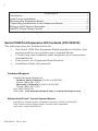
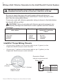
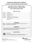
SERIAL COM PORT EXPANSION BOARD
FOR USE WITH INTELLITOUCH® AND EASYTOUCH®
CONTROL SYSTEMS
INSTALLATION
AND
USER’S GUIDE
IMPORTANT SAFETY INSTRUCTIONS
READ AND FOLLOW ALL INSTRUCTIONS
SAVE THESE INSTRUCTIONS
Serial COM Port Expansion Installation Guide
ii
CONTENTS
Introduction .......................................................................................... 1
Load Center Installation ........................................................................ 1
Mounting the Expansion Board ............................................................. 2
Connecting Accessories to the Expansion Board ................................. 2
Wiring a Salt Chlorine Generator .......................................................... 5
IntelliFlo Pump Wiring Pinouts .............................................................. 5
Serial COM Port Expansion Kit Contents (P/N 520818)
The following items are included in the kit:
• One Serial COM Port Expansion Board populated with three four
position and four two position screw terminal blocks.
• 12 inch long, four-conductor cable attached to two four-position
terminal blocks.
• Four-screws, two Expansion Board brackets
• Installation Guide (this manual)
Technical Support
Contact Technical Support at:
Sanford, North Carolina (8 A.M. to 4:30 P.M.)
Phone: (800) 831-7133
Moorpark, California (8 A.M. to 4:30 P.M.)
Phone: (800) 831-7133
Fax: (800) 284-4151
Web sites: visit www.pentairpool.com and www.staritepool.com
Related IntelliTouch® Control System Manual
IntelliTouch® Control System Installation and User’s Guide (P/N 521075)
EasyTouch® Control System Indoor Control Panel Installation
and User’s Guide (P/N 520617)
P/N 520817 - Rev C 4/13
Serial COM Port Expansion Installation Guide
iii
IMPORTANT WARNING AND SAFETY INSTRUCTIONS
SERIOUS BODILY INJURY OR DEATH CAN RESULT IF THIS
PRODUCT IS NOT INSTALLED AND USED CORRECTLY.
INSTALLERS, POOL OPERATORS AND POOL OWNERS MUST
READ THESE WARNINGS AND ALL INSTRUCTIONS BEFORE
USING THIS PRODUCT.
Most states and local codes regulate the construction, installation, and
operation of public pools and spas, and the construction of residential
pools and spas. It is important to comply with these codes, many of which directly
regulate the installation and use of this product. Consult your local building and
health codes for more information.
IMPORTANT NOTICE - Attention Installer: This Installation and User’s
Guide (“Guide”) contains important information about the installation,
operation and safe use of this underwater pool and spa light. This Guide
should be given to the owner and/or operator of this equipment.
Before installing this product, read and follow all warning notices
and instructions in this Guide. Failure to follow warnings and instructions can result in severe injury, death, or property damage.
Call (800) 831-7133 for additional free copies of these instructions. Please refer to
www.pentairpool.com for more information related to this products.
RISK OF ELECTRICAL SHOCK OR ELECTROCUTION:
BEFORE WORKING ON OR INSTALLING THIS PRODUCT, always
disconnect power to the pool and/or spa lights at the source
circuit breaker from the light before servicing the light. Failure
to do so could result in death or serious injury to service
person, pool users or others due to electric shock. When
installing and using this electrical equipment, basic safety
precautions should always be followed.
For countries in compliance with International Electrotechnical
Commission (IEC) regulatory standards: The light fixture must be
installed by a licensed or certified electrician or a qualified pool service person, in
accordance with current IEC 364-7-702 and all applicable local codes and ordinance.
Improper installation will create an electrical hazard, which could result in death or
serious injury to pool user, installer or other due to electrical shock and may also cause
damage to the property.
Serial COM Port Expansion Installation Guide
1
Introduction
The Serial COM port expansion board can be used with IntelliTouch® and
EasyTouch® Control Systems. Connect accessory equipment to the
Expansion Board as shown:
J3
Six two-pin
connectors:
For future
use.
J2
J1
Expansion Board
Three four-pin screw terminal blocks
(COM ports). One COM port must be
connected to the IntelliTouch´® Control
System Personality Board or the
EasyTouch® Control System Main Board.
For use with IntelliTouch control system
iS10 Remote Controller, QuickTouch®,
and MobileTouch® Wireless Controllers,
Indoor Control Panel, i5x and i10x
Expansion Load Center, EasyTouch
control system Control Panel, Wireless
Control Panel, ScreenLogic® Interface
Protocol Adapter, IntelliChlor® Electronic
Chlorine Generator, i-Link™ Protocol
Interface adapter, and many other
accessories. Note: The three COM Ports
share a common bus. These
accessories can attach to any of these
ports.
Four two-pin non-power
screw terminals. For RS-485
communication to IntelliFlo®
Pumps.
Load Center Installation
WARNING Switch OFF the main system power to the load center
before making any connections.
1. Unlatch the front door spring latch/latches to open the door.
2. Loosen the two access screws securing the control panel and fold it
down.
3. Proceed to “Mounting the Expansion board,” on page 2.
4. After the Expansion Board has been mounted and connected,
close the control panel into its original position and secure it with
the two access screws. Close the load center front door. Fasten the
spring latch/latches.
Control
panel
access
screws
Original Load Center Enclosure
Serial COM Port Expansion Installation Guide
Control
panel
access
screws
New Style Load Center Enclosure
2
Mounting the Serial COM Port Expansion Board
Note: The Serial COM Port Expansion Board is shipped with the cable
connectors plugged in to J2 and J3.
1. Remove the terminal connector J2 on the Expansion Board and
connect it to a COM port on the IntelliTouch® Control System
Personality Board or EasyTouch® Control System Main Board.
Note: If this a first time installation, remove one of the existing
(empty) terminal connectors from the Personality board main board
to allow for the Expansion board terminal connector. You can place
the (empty) connector onto the available COM port on the
Expansion board.
Note: A typical cable connection would be J3 cable connector remains on
the Expansion Board and the other cable connector is attached to the
Personality board or EasyTouch® Control System Main Board.
J2 J3
Remove this terminal connector J2
and connect it to an available COM
port on the Personality board or
EasyTouch® Control System Main
Board
IntelliTouch Control System Personality Board
2. Mount the Expansion board on to the back wall in the low voltage
compartment of the Load Center using the four adhesive backed
supports.
3. Proceed to “Connecting Accessories to the Expansion Board”.
Connecting Accessories to the Expansion Board
If you have existing accessories (IntelliChlor® Electronic Chlorine Generator,
IntelliFlo® Pump) connected to the IntelliTouch control System Personality Board
or EasyTouch Control System Main Board COM port, remove the connector with
attached wires and connect the connector to an available terminal on the Expansion board COM port (as shown on page 3).
Serial COM Port Expansion Installation Guide
3
Connect IntelliFlo® Connect existing
Pump wires to
accessory connectors
two-pin terminal
wires here
connector
Expansion
board use
adhesive
backed
supports (x4)
Connector at J3 on Expansion Board to COM port on
IntelliTouch® Control System
Personality board or
EasyTouch Control System
Main Board
Low voltage
compartment
Cables to
accessories
(IntelliChlor®,
Electronic
Chlorine
Generator, Indoor
Control Panel
etc.)
Figure 1. IntelliTouch® Control System
Connector from the
(Original) Load Center
Expansion board
Installing the Expansion Board in the EasyTouch® and IntelliTouch®
Control System Load Center
1. Remove the two screws from the back of the load center low
voltage compartment.
2. Install the two Expansion Board brackets and secure with the
two screws.
3. Mount the Expansion Board onto the bracket and secure with
the four screws that is provided in the kit.
Expansion
Board
Expansion
Board screw
(4x)
Bracket
screw (2x)
Bracket (2x)
Figure 2. EasyTouch and IntelliTouch Control System
(New Style) Load Center
Serial COM Port Expansion Installation Guide
4
Serial COM port
Expansion Board,
Indoor Control Panel,
IntelliChlor,
RF Transceiver.
EasyTouch® Main Board COM port location
1. Expansion board COM port connections: Connect the fourwire connector from the accessory to the COM port on the
Expansion board COM port. Accessories include the IntelliTouch®
Control System iS10 Remote Controller, QuickTouch®,
MobileTouch® Wireless Controllers, Indoor Control Panel, the
EasyTouch Control Systems Control Panel, Wireless Control
Panel, the ScreenLogic® Interface Protocol Adapter, or any
accessory that does not require a separate power supply.
2. Connecting COM port terminal connector wires: Strip back
the cable conductors ¼ in. Insert the wires into the screw
terminals of one of the COM PORT plugs. Using a small flat-blade
screwdriver, secure the wires with the screws. Make sure to
match the color coding of the four wires:
Pin 4 - Red = +15
Pin 3 - Yellow = +DT
Pin 2 - Green = -DT
Pin 1 - Black = GND
3. Four two-pin non-power (RS-485) connectors: Use these
connectors to connect to IntelliFlo® Pumps, Load Centers or any
accessory that uses a separate power supply.
Note: IntelliValve™ connectors: For future use.
Serial COM Port Expansion Installation Guide
5
Wiring a Salt Chlorine Generator to the IntelliTouch® Control System
IMPORTANT WIRING INFORMATION WHEN USING SALT CHLORINE
GENERATORS WITH INTELLITOUCH® CONTROL SYSTEM.
Be sure to check the wire color and function of the salt chlorine
generators before attaching to the IntelliTouch® Control System COM
port. See the wiring table below.
Commonly used salt chlorine generator wiring is shown in the table below
but should still be verified.
CAUTION! Failure to wire the salt chlorine generator properly can
permanently damage the IntelliTouch control system and the Chlorine
Generator.
IntelliTouch COM port
wire colors
RED
YELLOW
GREEN
BLACK
Chlorine Generator
commonly used wire
colors
Function
+15V
+DATA
-DATA
GROUND
RED
BLACK
YELLOW
GREEN
IntelliFlo® Pump Wiring Pinouts
•
Connect pin 6 (green) on the pump cable to pin 2 (green) on the
Expansion Board two-pin screw terminal.
•
Connect pin 7 (yellow) on the pump cable to pin 3 (yellow) on the
Expansion Board two-pin screw terminal.
Expansion Board
two-pin screw terminal
Yellow Green
Pin 6
(Green)
Pin 7 (Yellow)
IntelliFlo Pump
Cable Pinouts
Serial COM Port Expansion Installation Guide
IntelliTouch
screw terminal
connector
IntelliFlo
(2-w ire cable)
2 (GRN)
GREEN (Pin 6)
3 (YEL)
YELLOW (Pin 7)
Pinouts
6
Notes
Serial COM Port Expansion Installation Guide
1620 HAWKINS AVE., SANFORD, NC 27330 • (919) 566-8000
10951 WEST LOS ANGELES AVE., MOORPARK, CA 93021 • (805) 553-5000
WWW.PENTAIRPOOL.COM
All Pentair trademarks and logos are owned by Pentair, Inc. Pentair Aquatic Systems™,
IntelliTouch®, IntelliFlo®, IntelliChlor®, QuickTouch®, MobileTouch®, ScreenLogic® and
EasyTouch® are trademarks and/or registered trademarks of Pentair Water Pool and Spa, Inc. and/
or its affiliated companies in the United States and/ or other countries. Unless expressly noted,
names and brands of third parties that may be used in this document are not used to indicate an
affiliation or endorsement between the owners of these names and brands and Pentair Water Pool
and Spa, Inc. Those names and brands may be the trademarks or registered trademarks of those
third parties. Because we are continuously improving our products and services, Pentair reserves
the right to change specifications without prior notice. Pentair is an equal opportunity employer.
© 2013 Pentair Aquatic Systems. All rights reserved.
This document is subject to change without notice.
P/N 520817 REV C 4/13
Serial COM Port Expansion Installation Guide