1
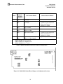
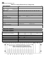
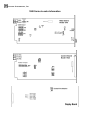
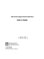
1900 Series Digital Antenna Monitors User's Guide February 1, 2000 File: 1900 Users Guide A-SS Potomac Instruments, Inc. 932 Philadelphia Avenue Silver Spring, Maryland 20910 Tel 301-589-2662 Fax 301-589-2665 Web Site: http://www.PI-USA.com Potomac Instruments, Inc. 1900 Series User's Guide Revised 020100 Table of Contents 1 MODEL 1900-SERIES INTRODUCTION................................................................................................... 1 2 INSTALLATION............................................................................................................................................. 4 2.1 UNPACKING ................................................................................................................................................... 4 2.2 RESHIPMENT TO FACTORY ............................................................................................................................. 4 2.3 INSTALLATION ............................................................................................................................................... 4 2.4 CONFIGURATION VERIFICATION ..................................................................................................................... 5 2.5 CONNECTING RF CURRENT SAMPLE INPUTS .................................................................................................. 7 2.6 CONNECTING EXTERNAL CONTROL INPUTS AND TELEMETERING OUTPUTS ................................................... 8 2.6.1 External Control Inputs........................................................................................................................ 8 2.6.2 Telemetering Outputs ........................................................................................................................... 9 2.6.3 Control/Display Panel, Model 1902 .................................................................................................... 9 2.6.4 AC Power Supply ............................................................................................................................... 10 3 OPERATION................................................................................................................................................. 11 3.1 OVERVIEW ................................................................................................................................................... 11 3.2 POWER ON AND INITIAL READINGS ............................................................................................................. 11 3.3 FRONT PANEL CONTROLS ............................................................................................................................ 11 3.3.1 Tower UP and DOWN Select Switches .............................................................................................. 11 3.3.2 MODE Select Switch .......................................................................................................................... 12 3.3.3 PATTERN Select Switch ..................................................................................................................... 12 3.4 FRONT PANEL DISPLAYS........................................................................................................................... 13 3.4.1 RATIO ................................................................................................................................................ 13 3.4.2 AMPLITUDE...................................................................................................................................... 13 3.4.3 PHASE................................................................................................................................................ 13 4 ADJUSTMENTS, MAINTENANCE, AND CONFIGURATION............................................................. 15 4.1 1910 METER MODULE ................................................................................................................................. 15 4.1.1 1910 Front Panel Adjustments ........................................................................................................... 15 4.1.2 1910 Metering Module PHASE Adjustment ....................................................................................... 15 4.1.3 1910 Metering Module RATIO Adjustment........................................................................................ 16 4.1.4 1910 Metering Module Replacement ................................................................................................. 17 4.1.5 1910 Metering Module CALibration .................................................................................................. 17 4.1.6 Changing Reference Tower Assignments ........................................................................................... 18 4.2 1920 CONTROL MODULE ............................................................................................................................. 21 4.2.1 1920 AMPLITUDE Adjustment.......................................................................................................... 21 4.2.2 1920 Module Configuration ............................................................................................................... 21 4.3 CALIBRATION REQUIREMENTS ..................................................................................................................... 23 4.4 TROUBLESHOOTING ..................................................................................................................................... 23 4.4.1 Warranty............................................................................................................................................. 23 4.4.2 Unit is Completely Inoperable ........................................................................................................... 23 4.4.3 Tower Readings are Unreliable or Incorrect ..................................................................................... 24 5 FACTORY CONTACT INFORMATION.................................................................................................. 26 NOTES .................................................................................................................................................................... 27 APPENDIX A - SAMPLE CONFIGURATION FOR MODEL 1901/1903 MONITORS ............................... 31 APPENDIX B - RETURN MATERIAL AUTHORIZATION FORM .............................................................. 35 i Potomac Instruments, Inc. 1900 Series User's Guide Revised 020100 List of Figures Figure 1. Model 1901 Stand-Alone Antenna Monitor Front Panel...........................................................1 Figure 2. Model 1903 Remote Reading Antenna Monitor Front Panel ....................................................1 Figure 3. Model 1902 Antenna Monitor Display and Control Panel ........................................................1 Figure 4. Model 1901/1903 Rear Panel Connections................................................................................6 Figure 5. 1902 Interconnect Cable Wiring .................................................................................................9 Figure 6. Model 1901 and 1903 Rear Panel Module Locations..............................................................15 Figure 7. Adjustments accessible by opening 1901/1903 Front Panel....................................................16 Figure 8. Model 1910 Meter Board Jumper Locations ...........................................................................17 Figure 9. Front Panel Display Board Jumper Locations .........................................................................21 Figure 10. Model 1920 Control Board Jumper and Adjustment Locations ............................................22 List of Tables Table 1. 1900 Series Equipment Specifications........................................................................................3 Table 2. 1902 Interconnect Cable Size and Length Requirements ..........................................................10 Table 3. Model 1910 Module Configurations .........................................................................................20 Table 4. 1910 Module Configuration Worksheet.....................................................................................20 Table 5. Module 1920 External Pattern Control Configurations .............................................................22 ii Potomac Instruments, Inc. 1 1900 Series Technical Manual Revised 020100 Model 1900-Series Introduction The Model 1901 and 1903 Antenna Monitors, and the Model 1902 Monitor Display are designed to monitor the relative phase angles and current ratios of antenna element currents for AM broadcast directional antennas with up to 12 towers. The units operate over the 540 kHz to 1700 kHz carrier frequency range. The Monitors accept sample voltages from sampling loops or transformers at each tower of the antenna, simultaneously measuring the phase angle and amplitude ratio of each, as they relate to the reference tower. Simultaneous phase and ratio voltages for all towers are available on the rear panel for remote telemetering monitoring. Front panel indicators digitally display the measurements for one tower at a time. Phase and ratio indications are essentially independent of transmitter power level and modulation. The display can be switched to indicate the amplitude of each sample input and monitor non-directional tower current. A self-test mode checks ratio and phase circuit operation. The Model 1902 Monitor Display allows remote display of measurements. It fully duplicates the frontpanel display and controls of the 1901 Monitor. The 1903 Monitor has no front-panel display or controls, and is used only with the Model 1902 to provide these functions. Figures 1, 2, and 3 illustrate the front panels for the Models 1901, 1903, and 1902, respectively. Figure 1. Model 1901 Stand-Alone Antenna Monitor Front Panel Figure 2. Model 1903 Remote Reading Antenna Monitor Front Panel Figure 3. Model 1902 Antenna Monitor Display and Control Panel 1 Potomac Instruments, Inc. 1900 Series Technical Manual Revised 020100 The 1900 Series products mount in standard EIA/RETMA equipment racks and cabinets. The Model 1901 and 1903 front panels are 5.25 inches (3-ru) high and the Model 1902 is 1.75 inches (1-ru) high. The units are set at the factory to operate on either 115 VAC or 230 VAC power. Units set for 230 VAC operation include a sticker on the power supply indicating the 230 VAC requirement. The 1901, 1902, and 1903 meet the requirements of the United States Federal Communications Commission (FCC) Rules, Section 73.53, for an Antenna Monitor used in accordance with Rules Section 73.69. Table 1 includes a complete set of specifications for the 1900 series monitor equipment. 2 Potomac Instruments, Inc. 1900 Series Technical Manual Revised 020100 SPECIFICATIONS Frequency Range RF Inputs Level range, reference Level range, non-reference Impedance Connector Ratio/Amplitude Display Ratio range Ratio accuracy Amplitude range 540 kHz to 1700 kHz 1.5 V to 25 V RMS carrier 0.3 V to 25 V RMS carrier 50 Ohms, 72 Ohms, or Special UHF, N, or adapters supplied for other types 0 to 1.999 ±0.010 0 to 1999, scale factor and decimal position user set Phase Display Range Accuracy Patterns 0 to ±180.0 degrees ±1.0 degree for ratios from 0.2 to 1.999 Up to 3 different reference towers; any number of power levels, subject to the input range limits. DC voltage proportional to parameter, separate outputs for each tower. 0 to 2.72 V for 0-1999 local display reading, for any decimal position 0 to ± 2.45 V corresponding to the range of 0 to ±180.0 degrees 1000 ohms ±1% Plug for each tower with screw clamp terminals For external pattern and mode selection. Contact closure or collector to ground, +5 V open circuit. 10 mA closed circuit. Remote Data Outputs Ratio/Amplitude Phase Source Resistance Connector External Control Inputs Dimensions Models 1901 and 1903 19-inch (48.26 cm) Rack Panel, 5.25 inches high (13.3 cm, or 3-ru), by14 inches (35.6 cm) deep. 17.5-inch (44.5 cm) rear panel width. 19-inch (48.26 cm) rack panel width, 1.75 inches (4.45 cm, or 1-ru) high, by 6 inches (15.24 cm) deep. 16.9-inch (43 cm) rear panel width. 117 VAC ±10%, or 234 VAC ± 10%, 50-60 Hz, 50 VA maximum for 115 VAC operation: MDL 3/4 for 230 VAC operation: MDL 3/8 Model 1902 AC Power: AC Mains Fuse Table 1. 1900 Series Equipment Specifications 3 Potomac Instruments, Inc. 2 2.1 1900 Series Technical Manual Revised 020100 INSTALLATION Unpacking The monitor is packed in a custom shipping carton. Inspect the carton for any signs of serious damage. Report any damage to the shipping company. Carefully remove the Monitor from the shipping carton. A technical manual and power cord are also included in the carton. It is recommended that the carton and packing materials be stored in case that the unit must be moved or shipped. In most cases, the Monitor will be ready to operate when it is unpacked. Prior to shipment, the Monitor is factory configured to specific operational data obtained from the station at the time of order. All Model 1901 and 1903 units shipped after January 1, 2000, include configuration sheets located under the top cover of the monitor. The configuration sheets include the specific internal settings for all modules. Blank copies of the configuration sheets are included as Appendix A of this manual.. It is recommended that copies of these sheets be made and updated with new configuration information if changes must be made in the field. 2.2 Reshipment to Factory If at all possible, the unit should be shipped in its original carton if it must be returned to the factory. Shipping cartons can be ordered from the factory if other suitable packaging is not readily available. Contact information can be found in Section 5 on page 26 of this manual. NOTE A Return Material Authorization (RMA) number must be obtained prior to returning a unit to the factory. A copy of a Return Material Authorization form is included as Appendix B to this manual. Please call, fax, or e-mail the factory to obtain an RMA number. Please also fax a copy of the RMA to the factory and include a copy of the RMA in the carton with the unit. Contact information can be found in Section 5 on page 26 of this manual. 2.3 Installation After unpacking the unit, installation consists of: 1. Verification that the monitor configuration is correct for the station 2. Mounting the Monitor in a suitable location 3. Connecting the RF current sample inputs 4. Connecting external control inputs and telemetering outputs 5. Supplying AC (mains) power to the Monitor. Note When monitors are replaced in stations licensed by the United States Federal Communication Commission (FCC), the station personnel must comply with Rules Section 73.69(d) which specifies the procedure for changing the licensed values to those obtained with the new monitor. 4 Potomac Instruments, Inc. 2.4 1900 Series Technical Manual Revised 020100 Configuration Verification When a new unit arrives from the factory it should already be fully configured for the specific installation. Verification should only require a review of the shipping papers included with the unit. Under certain circumstances, such as after maintenance, repair, or station reconfiguration, it may be necessary to set some of the internal programming jumper plugs as described in Section 4. The following paragraphs provide detailed verification information. AC Mains Power. All 1900 Series units are internally configured at the factory to operate from either 115 VAC or 230 VAC mains power. Soldered jumpers and voltage-specific MOV surge protectors determine the input voltage requirements. Power requirements are specified at time of purchase. Units for use within the USA are generally configured to operate on 115 VAC. Labels on the Model 1930 Power Supply indicate when a unit has been configured for 230 VAC operation. Severe damage to the unit may result if 115 VAC units are operated from 230 VAC. Units will not operate if configured for 230 VAC, but are powered from 115 VAC. Please contact the factory if input voltage changes are required. Pattern Control Mode. The pattern control mode determines the effects of the PATT select switch and the actions of grounding the DAY, NIT, or 3RD contacts located on the 1920 Control Module. The 1920 Control Module’s Pattern Control Mode are factory configured, as requested, at time of purchase. Figure 4 illustrates the connection locations on the 1920 Control Module. The three pattern selections are non-latching, e.g., they are only in effect while activated (contact closure to ground). Refer to Section 2.6 for additional information. Refer to Section 4.2 for information regarding 1920 Control Module internal configuration. 5 Potomac Instruments, Inc. 1900 Series Technical Manual Revised 020100 Figure 4. Model 1901/1903 Rear Panel Connections 6 Potomac Instruments, Inc. 2.5 1900 Series Technical Manual Revised 020100 Connecting RF Current Sample Inputs Each Model 1910 Metering Module includes a Type-N or UHF (PL-259) coaxial connector RF input. It is recommended that the sample cables from the antenna towers be marked with their respective tower numbers. Connect each tower sample cable to the 1910 module that matches the tower number. When facing the 1901/1903 rear panel, the inputs must be connected in the following order, starting at the left side: (1) Day reference (2) Night reference, if different from Day (3) 3rd reference, if different from Day and Night (4) All others follow in ascending order (5) Last is the common point, if that is to be monitored The maximum input voltage to a Model 1910 Metering Module is 25 V rms carrier, and the minimum reference input is 1.5 V rms. Input impedance is determined at the time of purchase, and should match that of the cables. Input impedance can be verified with an ohmmeter by measuring the resistance of the modules input terminating resistor. The resistance should indicate 51 or 75 ohms from the input connector center pin to ground. Parallel operation with another Antenna Monitor, while maintaining correct sampling line termination is possible, as the 1910 Module's input terminating resistor (R101) lead can be easily unsoldered if the module is removed from the chassis. The input exhibits a high input impedance when R101 is disconnected. DANGER SAFETY NOTE – HIGH TEMPERATURE! At maximum input voltage, the temperature of the sample cable connector and 1910 panel can be as high as 90ºC (194ºF). Protect yourself with tools or gloves if you must remove the cable. DANGER SAFETY NOTE – HIGH VOLTAGE! If your site uses sampling loops rather than toroids, and the sampling line is near a quarterwavelength long, its center pin voltage may be as high as several hundred volts when the line is disconnected from the 1910 terminating input! 7 Potomac Instruments, Inc. 2.6 1900 Series Technical Manual Revised 020100 Connecting External Control Inputs and Telemetering Outputs Figure 4, on page 6, illustrates the rear panel connections for the Model 1901 and 1903 Antenna Monitors. 2.6.1 External Control Inputs The external control inputs allow remote or automatic function selection similar to the manual selections that can be made from the front panel. External control inputs normally override local front panel control. Section 4.2.2, and Table 5, provide connection and function information related to External Control Inputs through the 1920 Control Module. Typical operation includes external control from phasor contacts that switch the Monitor to the correct pattern when the antenna pattern has been changed. Connecting the desired function pin to ground activates the command. For example, connecting the DAY pin (#4) on the 1920 Control Module terminal block to the GND (#1, Ground) pin, will select the DAY pattern information. It should be noted that pattern switching, either front panel or external, is only needed if more than one reference tower is used, or if a change of scale factor for the Amplitude Mode is desired at pattern change. For a single reference tower and Amplitude scale factor for all patterns, no Monitor switching is needed. Connections are also available on the 1920 Module to set the 1901 to the AMPLITUDE and TEST Modes. The control inputs can be paralleled with the status inputs of the Potomac RC-16 or 1500 Remote Control Systems. Control is effected only while the contact is closed. That is, there is no latching, except for the TU terminal (#7), which increments the tower selection up one digit for each momentary closure. The connector body on the 1920 module may be unplugged for wiring and then reinstalled. To remove it, simply pull it straight off. 8 Potomac Instruments, Inc. 1900 Series Technical Manual Revised 020100 2.6.2 Telemetering Outputs The Telemetering Outputs on the 1910 modules provide continuously available analog voltage outputs for each RF input. The RATIO/AMPLITUDE output full scale voltage is +2.72 VDC for a Monitor display indication of 1999, for any decimal point position. The PHASE full scale voltage is ±2.45 VDC for ±180 degrees, with the voltage polarity indicating the phase sign. NOTE Note that the 1910 module connectors have wires installed on positions 1 and 2. These are part of the ratio calibration circuit. If the wires must be temporarily removed, replace the wires exactly as found and do not change their length; they should extend back from the rear panel rather than lying flat against it, and other wiring should be routed away from them. The connector body containing the screw clamps may be unplugged for wiring and then reinstalled. 2.6.3 Control/Display Panel, Model 1902 A Model 1902 Control and Display unit can be connected to the upper half of the 1920 Module rear panel connector. The Model 1902 duplicates the Monitor's display and controls at a remote point. Its controls, and the Monitor's controls, can both be used at all times except when overridden by external control inputs. Cable assembly information can be found in Figure 5. Table 2 lists minimum recommended wire size for the +15 and –15 volt supply lines. 1902 9-pin “D ” Fem ale P/N 117D E9S 1 2 3 4 5 6 7 8 9 1901 8-pin Phoenix Plug P/N 17-57-07-7 16 GN D 20 O hm s M axim u m 20 O hm s M axim u m 15 14 13 12 11 10 9 P air Phase Ratio/A m plitude P air Tow er N o. V Ref. Analog Com -15 V +15 V Figure 5. 1902 Interconnect Cable Wiring 9 P air Potomac Instruments, Inc. 1900 Series Technical Manual Revised 020100 Shielded data cable is recommended for connecting a 1902 Display unit to a 1901 or 1903. For short lengths the type of cable is not critical. For longer lengths, low-capacitance, twisted-pair cable with high insulation resistance is required. The dashed lines in Figure 5 indicate which functions that should share a pair within a multiple pair cable. Wire size is not critical except for the 15 volt supply wires, which must not exceed a total of 0.1 uF between wires of a pair, or 0.2 uF between each wire and all others connected to the shield. Wire Size for +15 volt and –15 volt supply lines Number 26 AWG Number 24 AWG Number 22 AWG Number 20 AWG Number 18 AWG 2-Strand #20 3-Strand #22 4-Strand #24 Maximum Length Feet Meters 400 120 600 180 1000 300 1800 540 3300 1000 3300 1000 3300 1000 3300 1000 Table 2. 1902 Interconnect Cable Size and Length Requirements At lengths up to 500 feet / 150 meters, foil-shielded cable with unpaired #24 wires, such as Belden #9538 has been used. At a length of 3300 feet / 1000 meters, low-capacitance cable such as Belden #9830 or 9833 is required. With #9830 (3 pairs), a separate cable with two #18 wires is used to supply the +15 V and -15 V power. With #9833 (7 pairs), the four wires of two pairs are paralleled for the +15, and similarly for the -15 V. Cable having individually shielded pairs can be used if it has sufficiently low capacitance. 2.6.4 AC Power Supply The correct AC Mains supply voltage is marked on the 1930 Module rear panel. If the unit has been configured for 230 VAC operation a red label will indicate 230 Volts. For 230 VAC operation the unit should be operated with a type MDL 3/8 ampere fuse. 10 Potomac Instruments, Inc. 3 3.1 1900 Series Technical Manual Revised 020100 OPERATION Overview Ratio, amplitude, and phase are displayed on the 1901 Monitor or the 1902 Display/Control for one tower at a time. Towers are selected for display as required. When using the 1902 with the 1901, the same display of tower number, ratio, and phase appears on the panels of both units, and tower selection can be done at any time at either panel. You can prevent control of the 1901 from the 1902 by unplugging its connector. Control from either panel is referred to as LOCAL control. A second control option is external control (EXT) which refers to switching the Monitor to the desired pattern using external contact closures from the phasor or other source. A second monitoring method for the 1901 and 1903 Monitors is to use the simultaneous analog outputs provided for each tower as described in Section 2.6.2. These outputs can be connected to the telemetering inputs of a remote control system. The analog outputs could also be connected to an array of meters to display all values at once, which could be useful during maintenance or tuning. Monitor display selections have no effect on these outputs. 3.2 Power ON and Initial Readings Turn the Monitor on by placing the rear panel power switch in the UP position. The Power Indicator should illuminate. With no external control inputs, the front panel indicators should initially show TOWER 1, RATIO mode, LOCAL control, and DAY pattern. With external control, the indicators should show EXT control and the externally-set pattern. If there is no RF input, the Ratio and Phase displays should show all zeros, except possibly the last digit. The Phase sign may change periodically between plus and minus. With normal RF inputs, the ratio and phase values for Tower 1 should be displayed, and the other tower values can be selected for display by using the UP and DOWN switches as described below. 3.3 Front Panel Controls 3.3.1 Tower UP and DOWN Select Switches Momentarily pressing either the UP or DOWN switches will step the displayed tower number (for which ratio and phase is displayed), up or down by one step. The switches cycle through the towers repeatedly. For example, in a three-tower array, with the Monitor initially on Tower 1, the UP Switch selects towers in the sequence 2, 3,1, 2, 3, 1. . . Repeatedly pressing the DOWN Switch selects in the sequence 3, 2,1, 3, 2,1. . . 11 Potomac Instruments, Inc. 1900 Series Technical Manual Revised 020100 3.3.2 MODE Select Switch The MODE select switch steps the Monitor display through three operational modes, RATIO, AMPL, and TEST, as indicated by LED "bullets" on the display. RATIO Mode. In RATIO mode, the display shows the ratio of the selected tower sample voltage to that of the reference tower. AMPL Mode. In the AMPL mode, the display shows the amplitude of the selected tower sample voltage. The scale factor is factory set to read RMS carrier volts directly. The scale factor can be adjusted. Refer to Section 4.1.1 for adjustment information. TEST Mode. In the TEST mode, all elements of the display light for approximately one second, similar to a "lamp test." The Ratio display then goes to a test mode in which all tower inputs receive the same input. The normal reading should be between .999 to 1.001. The Phase display selects a180 degree test. The normal reading should be between 179.7 and 180.0. If the reference tower RF input level is below the value needed for accuracy, both displays show near zero. 3.3.3 PATTERN Select Switch The Pattern (PATT) select switch steps the Monitor through the patterns used by the station, as indicated by LED "bullets." The PATT switch is enabled for normal operation if the LOCAL "bullet" display is illuminated. If the EXT bullet is illuminated, it means that the selections are being made from an external source, and the PATT switch is disabled under these conditions. Note that the only Monitor parameters changed by pattern switching are the reference tower and the AMPL mode scale factor. If these are the same for all patterns, no switching is required. This is also the case if there is only a single pattern (DA-1). If no switching is needed, the PATT switch can be "locked out" by installing a jumper wire on the 1920 Module rear panel from Terminal 1 (GND) to any of the pattern terminals (DAY, NIT, or 3RD). The corresponding pattern indicator LED and the EXT LED will then always be on. To disable external input overrides of local pattern selection at all times, it is possible to have them take over only when the PATT switch selects EXT, or not at all. These modes are selected by moving jumper plugs on the 1920 Module, as described in Section 4.2.2 on page 21. 12 Potomac Instruments, Inc. 3.4 1900 Series Technical Manual Revised 020100 Front Panel DISPLAYS 3.4.1 RATIO The ratio of the selected tower sample voltage to that of the reference tower is displayed directly, up to a maximum of 1.999. Because the indicating device is a 3-1/2 digit voltmeter there is a ±1 digit possible variation in the reading. A ratio of 1.000 could be displayed as 1.001 or 0.999. This is well within the accuracy requirement of the Monitor. There is usually no variation with modulation or power level. Ratio error is estimated not to exceed 0.2%. A new Monitor is factory-adjusted to give ratio indications of 1.000 with equal inputs at the customer's operating frequency. If it is used at a different frequency, readjustment may be required (see Section 4.1.3 for information on adjusting the ratio display). 3.4.2 AMPLITUDE The amplitude (AMPL) of each sample voltage is displayed on the 3-1/2 digit display. A potentiometer for each pattern is located near the upper left corner of the backplane board. It is visible when the hinged front panel is opened. It sets the scale factor, which is the ratio of display indication to input voltage. A jumper plug on a three-position jack JP1 on the display circuit board sets the decimal point position. The potentiometers are factory set to read input RMS carrier volts directly, up to 19.99 volts. For greater voltage, the display will blank, indicating meter over-range. If this should happen, the front-panel AMPL potentiometer needs to be readjusted (see Section 4.2.1for information on adjusting the Amplitude display.). The potentiometers can also be set to make the amplitude values match the base current values. The display has a slow response to reduce the variation with modulation. The normal phase indication for a non-reference tower will be very close to 90.0 degrees when reading tower sample voltage in the AMPL mode, and without voltage on the reference input. 3.4.3 PHASE The phase angle of the selected tower sample, with respect to the reference sample, is displayed on a 3-1/2 digit display with 0.1 degree resolution. The ±1 digit variation means that the 180 test reading can be 179.9 or 180.1. The sign of the angle, + for leading and - for lagging, is automatically displayed. The variation with modulation is usually small, but may be significant when the selected tower bandwidth differs from that of the reference tower. For this reason the phase display also has slow response. In order to improve phase accuracy for most angles, the phase circuits are adjusted to indicate 0.0 to 0.2 degrees at zero degrees and 179.5 to 180.0 degrees at180 degrees. When the input phase angle changes through zero, the reading may change from +(0.1 to 0.2) to -(0.1 to 0.2), and may or may not show 0.0. There is no front panel zero adjustment. When the input phase angle changes through 180 degrees, the reading changes from +(179.5 to 180.0) to -(179.5 to 180.0), and may or may not show 180.0. This is controlled by the front panel PHASE adjustment described in Section 4.1.2. 13 Potomac Instruments, Inc. 1900 Series Technical Manual Revised 020100 When comparing phase readings with those of other Monitors, note that differences of 0.5 degree are within the probable accuracy of most Monitors, and a greater difference is allowed by published accuracy specifications. When the same phase difference is read on the various inputs of a Model 1901, the measurements should agree within 0.3 degree, but may differ more for a tower that is the reference tower for a pattern other than the current pattern. NOTE When the reference tower input voltage is too low for accurate phase and ratio readings, the phase and ratio displays go to zero. This occurs at a voltage of 0.6 to 0.7 vrms. The reference input must be above this value for normal readings to be obtained in the TEST Mode. 14 Potomac Instruments, Inc. 4 1900 Series Technical Manual Revised 020100 ADJUSTMENTS, MAINTENANCE, and CONFIGURATION The following adjustments, accessible without removing the Model 1901 or 1903 from its rack, need to be checked whenever a Model 1910 Metering Module is replaced in the field. Otherwise, only occasional checks of the PHASE and RATIO adjustments are suggested. Inadvertent, or unwanted changes in these adjustments should be discouraged by placing tape seals over the access holes. Figure 6 shows the rear panel module locations. Note that the 1910 Modules can be placed into slots A through L, as shown in the diagram. The lettering scheme is only used for clarification purposes in this manual. The letters do not actually exist on the chassis or modules. Also note that not all metering module slots will be filled. One metering module is installed for each tower. Figure 6. Model 1901 and 1903 Rear Panel Module Locations 4.1 1910 Meter Module 4.1.1 1910 Front Panel Adjustments Front-panel adjustments for each tower are located behind the hinged front panel. Figure 7 shows the locations of the adjustments on the backplane printed circuit board as they would be seen when looking into the unit from the front. 4.1.2 1910 Metering Module PHASE Adjustment To adjust the phase for each tower, use the MODE switch to select TEST. Adjust the potentiometer for each tower for a phase reading of 180.0. First adjust for a lower value, approximately 179.8, and then turn the potentiometer slowly clockwise, stopping 1/8-turn past the point where the reading first changes to 180.0. It is not essential to perform this adjustment unless the reading is outside of the range 179.9 to 180.1. The change in a phase reading caused by changing this setting by 0.2 is only about 0.1 per cent of the reading at 180 degrees. An RF input must be present on the DAY reference input for this test. 15 Potomac Instruments, Inc. 1900 Series Technical Manual Revised 020100 4.1.3 1910 Metering Module RATIO Adjustment To adjust the ratio for each tower, use the MODE switch to select TEST. For each tower, except the one used as reference (normally the DAY reference tower), adjust the potentiometer for a ratio reading of 1.000. First, adjust for a lower value, approximately 0.998, and then turn the potentiometer slowly clockwise, stopping 1/8-turn past the point where the reading first changes to 1.000. CAUTION Do not adjust the reference tower potentiometer, as doing so changes the ratio reading of all other towers. For this reason a tower number label may be placed over the access hole of the ratio test reference potentiometer. It is not essential to perform this adjustment unless the reading is outside the range .998 - 1.002. A change in a ratio reading of 0.002 is only 0.2% of the reading. An RF input must be present on the DAY reference input for this test. Figure 7. Adjustments accessible by opening 1901/1903 Front Panel 16 Potomac Instruments, Inc. 1900 Series Technical Manual Revised 020100 4.1.4 1910 Metering Module Replacement When replacing a 1910 Metering Module the jumper plug(s) must first be installed on the new module exactly as they are installed on the module to be replaced. All modules have one plug on JP2 or JP3 on the pin pair corresponding to the tower number, which is usually the same as the number of the tower being monitored. A reference tower module, or a module used in a non-directional mode, has a plug on the pin pair of JP1 corresponding to the pattern, indicated by REF-DAY-NIT-3RD markings. All reference tower modules, but no others, have a plug on JP4. The module used as ratio reference for the TEST mode, normally the DAY reference module, has a plug on JP6, except on module Serial Numbers 0030 and below. These have a shorting wire soldered from one side of the small inductor on the upper end of the input power resistor (R101), to one relay pin; this must be duplicated on the new module. All Modules of a given 1901 have a plug on the same position of JP7, upper or lower. After installing the module, perform the PHASE and RATIO adjustments described above, and the CALIBRATION described below. Figure 8 shows the location of the 1910 Jumpers. Figure 8. Model 1910 Meter Board Jumper Locations 4.1.5 1910 Metering Module CALibration The CALibration adjustments will be found on the 1910 modules at the rear panel of the 1901 or 1903. Access to the adjustment is through a small hole located just below the connector terminals. This is for phase trim adjustment, and is normally a factory-only adjustment. It is adjusted for each selected tower to obtain the minimum phase reading (the point near zero reading at which the phase sign changes) with signals of equal amplitude and zero phase difference applied to the selected and reference towers. In the field, this can be done only by using a "Y" adapter cable with exactly equal length branches so that the reference tower sampling line can drive both inputs with zero phase difference and equal amplitude. The cables should be less than 2 feet in length. 17 Potomac Instruments, Inc. 1900 Series Technical Manual Revised 020100 When replacing a 1910 module, it can be set by connecting another sampling line and adjusting for the same phase reading as was just obtained for that line on another module. If there are separate reference towers for DAY and NIGHT, a compromise adjustment for each nonreference tower that minimizes the zero error is used. Adjust with zero phase difference inputs to the DAY and NIGHT reference modules to make equal the zero-phase reading for one with the other as reference. Since the CAL adjustment has a small effect on ratio calibration, perform the RATIO adjustment after resetting CAL. All circuit board adjustments are intended as factory adjustments only. 4.1.6 Changing Reference Tower Assignments 1901 Monitor reference tower assignments can be changed in the field. This is done by changing 1910 Module reference assignments. A module can be designated as either a reference or non-reference module. If it is designated as a reference module, it is further defined for the pattern and tower number assignments associated with the pattern .Each module remains in the rear panel slot where it was installed at the factory. The first step determines the reference and tower number assignment of each 1910 Module in the present Monitor configuration. The second step determines what the reference and tower number assignment of each module will be in the new configuration. The third step makes changes in each module for the new assignments. Please read all the following steps the before proceeding. For all units shipped after January 1, 2000, a complete factory configuration can be found by removing the Monitor's top cover. Blank copies of the configuration sheets are included in Appendix A of this manual. It is strongly recommended that "before and after" configurations are recorded and maintained. Step 1 Table 3 shows all possible 1910 Module reference assignments for each of the module positions in the 1901, and for all possible 1901 configurations. The module positions are given letter designations (A, B, C, D) starting at the left-hand side of the 1901 rear panel (they are not actually so marked). Only these four positions are shown because the modules in positions D and higher (to the right) are always non-reference modules. Figure 6 on page 15 shows the module locations when viewing the back of the Monitor. From Table 3, select the configuration matching the Monitor being changed. Then copy the reference assignments from Table 3 for the selected configuration into the blank spaces in Table 4 in the REF–OLD row, for positions A thru D (all other positions are Non Reference). If there is any doubt about whether an existing module is a reference module, remove the module from its slot and look at JP4 at the lower left corner of the circuit board. The module is a reference module if there is a jumper plug on JP4. Jumper plugs on JP1 select the pattern. The first module on the left (position A) will also have plugs on JP6 and JP7. Reinstall the module in the same slot. Figure 8 on page 17 shows the jumper locations. 18 Potomac Instruments, Inc. 1900 Series Technical Manual Revised 020100 Step 2 From Table 3, select the desired new Monitor configuration. In Table 4, copy the reference assignments for the selected new configuration into the REF–NEW row for positions A thru D. Step 3 Referring to the Monitor being changed, write into the Table 4 TWR–OLD row, the tower number assigned to each module position used. Step 4 Write into the Table 4 TWR–NEW row the new tower number for each module position, as dictated by the new reference assignments. Step 5 In Table 4, note the module positions where the REF-NEW and REF-OLD entries differ. Also note the positions where the TWR-NEW and TWR-OLD entries differ. Make module changes in these positions, first in circuit board jumper settings and then in tower number labeling. Refer to Figure 8 on page 17 for the jumper locations. Proceed as follows: (a) If a non-reference module changes to a reference module, remove that module from its slot. Install a jumper plug on JP4. Also, install a plug on JP1 to select the pattern type. If the tower number for this module changes, locate the tower number plug on JP2-JP3 and move it to the pins for the new tower number. Reinstall the module in its slot. (b) If a reference module changes to a non-reference module, remove the module from its slot and remove jumper plugs from JP1 and JP4. If the tower number for this module changes, re-locate the tower number plug on JP2-JP3 as required. Reinstall the module in its slot. (c) For any other module where the reference assignment does not change, but the tower number changes, remove the module from its slot, locate the tower number plug on JP2-JP3, and move the plug to the pins for the new tower number. Reinstall the module in its slot. (d) On the rear panel of modules where the tower number has changed, remove the selfadhesive tower number labels and reinstall them to agree with the TWR–NEW row of Table 4. (e) At the 1901 Monitor front panel, open the hinged door. There are tower number labels on the circuit board into which the modules are plugged. Where the tower number assignments have changed, remove and reinstall the labels to agree with the changes of Step 5(d). This completes the procedure. Figure 7 on page 16 shows the module locations as they appear with the front panel open. 19 Potomac Instruments, Inc. 1900 Series Technical Manual Revised 020100 1910 Module Position → DA-1 A B C D RD NR NR NR RD RN NR NR RDN NR NR NR RD RN R3 NR RD RN3 NR NR RDN R3 NR NR RDN3 NR NR NR DA-2 Directional Antenna → and 1901 Monitor Configuration DA-3 Key RD = Day Reference RN = Night Reference R3 = 3RD Refernce RDN = Day + Night Reference RN3 = Night + 3RD Reference RDN3 = Day + Night + 3RD Reference NR = Non Reference Table 3. Model 1910 Module Configurations Position → A B C D E F G H REF-OLD REF-NEW TWR-OLD TWR-NEW Table 4. 1910 Module Configuration Worksheet 20 I J K L Potomac Instruments, Inc. 4.2 1900 Series Technical Manual Revised 020100 1920 Control Module 4.2.1 1920 AMPLITUDE Adjustment Open the Monitor's front panel to access the adjustment potentiometers. Figure 7 on page 16 shows the adjustment locations. The three potentiometers marked DAY, NIGHT, and 3RD, are adjusted in the AMPL mode to set the amplitude scale factor. To adjust, select the desired pattern and adjust the corresponding potentiometer for the desired AMPL indication. The potentiometers are factory adjusted so that the display indicates the actual input rms carrier voltage up to 19.99 Volts. Above that level, the display will blank. A three-position jumper plug on the front panel Display circuit board (rear of front panel) sets the decimal point position, which is the same for all patterns. Figure 9 shows the location of the decimal point selection jumpers. Figure 9. Front Panel Display Board Jumper Locations 4.2.2 1920 Module Configuration Table 5 lists the pattern control modes available by configuring the 1920 Control Module. The mode is set through internal 1920 Control Module movable jumpers JP1 and JP8. JP1 and JP8 are located on the 1920 printed circuit board which is accessible when the module is removed from the chassis. Using the movable jumpers, each can be set to Position 1, Position 2, or Position 3 as marked on the PC board. Figure 10 illustrates the jumper locations. For a one-pattern, or two pattern monitor, the standard factory setting is Mode B. Mode E is normally used for monitoring a three-pattern system. A one-pattern system monitor configuration can be set by connecting a wire from the appropriate terminal (DAY, NIT, or 3RD) on the 1920 module, to ground (GND). 21 Potomac Instruments, Inc. Mode A B C D E 1900 Series Technical Manual Revised 020100 Module 1920 JP1 and JP8 Positions JP1, 1 JP8, 2 JP1, 1 JP8, 3 Toggles between Local Day / Local Night Toggles between Local Day / Local Night JP1, 2 JP8, 1 JP1, 2 JP8, 2 JP1, 2 JP8, 3 Repeats through Local Day, Local Night, and EXT. Repeats through Local Day, Local Night, Local 3RD. Repeats through Local Day, Local Night, and Local 3RD. PATT Switch Effects F Contact Closure Effects* Disabled Sets 1901 pattern selection regardless of previous selection PATT switch disabled EXT ON, Local OFF Selects pattern only when EXT is ON. Disabled Sets 1901 pattern selection regardless of previous selection PATT switch disabled EXT ON, Local OFF Sets pattern only when EXT is ON JP1, 3 Repeats through Local Day, Local JP8, 2 Night, Local 3RD, and EXT. * Remote Options by contact closures on 1920 Control Module terminals: DAY to Ground selects DAY Pattern NIT to Ground selects NIGHT Pattern 3RD to Ground selects 3rd Pattern Table 5. Module 1920 External Pattern Control Configurations Figure 10. Model 1920 Control Board Jumper and Adjustment Locations 22 Potomac Instruments, Inc. 4.3 1900 Series Technical Manual Revised 020100 Calibration Requirements The units may change slightly with aging, heat, and humidity. It is recommended that a log of quarterly readings be maintained. The unit should be re-calibrated if the readings begin to shift considerably from the readings obtained when the unit was first installed. At a minimum, calibration should be considered at least every 60 months. Please refer to Section 2.2 on page 4 for details on sending the unit back to the factory. 4.4 Troubleshooting The Monitors are generally not considered field repairable except by module replacement. A unit should be returned to the factory for repair and refurbishment if it has been damaged by lightning, excessive heat or humidity, or by flooding. Instructions for returning the unit to the factory can be found in Section 2.2 on page 4. 4.4.1 Warranty Units that are under warranty should be returned to the factory for any needed repairs. Potomac Instruments warrants each new equipment to be free of defects in material and workmanship, for a period of one (1) year after date of original shipment, except for fuses, transistors, diodes, and integrated circuits, which are warranted for a period of ninety 90 days. Any instrument which is found within one year not be meet the foregoing standards after examination by our factory, will be repaired or at the option of Potomac Instruments replaced without charge. This warranty does not apply to equipment which has been altered, improperly handled, or damaged in any way. 4.4.2 Unit is Completely Inoperable If the unit appears to be completely inoperable, first check to ensure that it is receiving proper AC power and that the power switch on the rear panel has not been accidentally turned to the OFF position. Remove the fuse and verify that it is good. Units configured for 115 VAC use a 3/4 ampere fuse. Units configured for 230 VAC use a 3/8 ampere fuse. Do not substitute fuse values. The power supply can be checked with a voltmeter by opening the monitor front panel. After opening the front panel, first verify that the ribbon cable connecting the backplane board to the display board has not become loose or disconnected. The connectors on the backplane board and the display board both indicate the pin one location for the cable connector. If the cable has been disconnected, make sure that the cable is oriented so that pin 1 on the backplane board connects to pin 1 on the display board. To check the power supply operation with the front panel open, locate the test points on the front panel display board. Refer to Figure 9 on page 21 for the location of the test points. The voltage should be measured from TP3 (Ground) to each of voltage test points. TP1 should read +5 VDC ± 0.2 volts. TP2 should read -5 VDC ± 0.2 volts. TP4 should read +15 VDC ± 0.2 volts. TP5 should read -15 VDC ± 0.2 volts. 23 Potomac Instruments, Inc. 1900 Series Technical Manual Revised 020100 If any of the voltages are significantly higher than the specified voltage the power supply should be checked and/or replaced. Significantly higher voltages may also have damaged other components within the unit. Under these conditions the entire assembly should be returned to the factory for repair. If any of the voltages are significantly lower than the expected voltage, a problem may exist with either the power supply or one of the other modules. Turn OFF the power supply switch on the rear panel power supply. Unplug each of the metering modules and the control module at the rear of the unit. The modules do not need to be fully removed. They should just be disconnected from the backplane board. Turn the power switch back ON and re-test the voltages at the display board test points. If the voltages are still out of specification, the power supply may need to be repaired or replaced. If the voltages are within specifications with the modules unplugged, turn OFF the power again and repeat the above procedure after plugging the modules in one at a time. If a particular module causes the power supply voltage problem, the module should be repaired or replaced. 4.4.3 Tower Readings are Unreliable or Incorrect If readings appear to be incorrect or unreliable, it must be determined if the problem is the sampling signal from a tower or a problem with a metering module. To isolate the problem to a module or a sampling signal, note the readings from a metering module that is operating correctly. Disconnect the sampling line from the metering module associated with the incorrect reading. Then disconnect the sampling line from the metering module that is providing a correct reading, and connect it to the metering unit that was not providing a correct reading. Now monitor the readings from that metering module. If the readings are still incorrect or unstable, the metering module may need to be replaced or repaired. If the readings are correct and stable, a problem exists with the sampling line from the tower. DANGER SAFETY NOTE – HIGH TEMPERATURE! At maximum input voltage, the temperature of the sample cable connector and 1910 panel can be as high as 90ºC (194ºF). Protect yourself with tools or gloves if you must remove the cable. DANGER SAFETY NOTE – HIGH VOLTAGE! If your site uses sampling loops rather than toroids, and the sampling line is near a quarterwavelength long, its center pin voltage may be as high as several hundred volts when the line is disconnected from the 1910 terminating input! 24 Potomac Instruments, Inc. 1900 Series Technical Manual Revised 020100 If a metering module is found to have a problem with incorrect or inconsistent readings, it is possible that the terminating resistor R101 has become damaged. R101 can be checked with an Ohm meter by checking the resistance from the RF input of the module, to the chassis. The reading should match the impedance of the sampling line, that is it should either read approximately 50 Ohms or 75 Ohms. (If the Monitor is used in parallel with another monitor, it is possible that the resistor has been disconnected, in which case, the resistance should read over 10,000 Ohms.) The resistor should be replaced with an exact replacement from the factory if it is found to be defective. 25 Potomac Instruments, Inc. 5 1900 Series Technical Manual Revised 020100 Factory Contact Information By Postal Mail Potomac Instruments, Inc. 932 Philadelphia Avenue Silver Spring, Maryland 20910 USA By Telephone or Fax Tel. 1-301-589-2662 Fax 1-301-589-2665 Country Code 1, North American Area Code 301 North American Eastern Time Zone (GMT -5) By Internet/World Wide Web Website: http://www.PI-USA.com E-Mail: [email protected] Please check our website for the latest technical notes, information, and worksheets. The latest revision of this technical manual is also available for viewing and downloading from our website. 26 Potomac Instruments, Inc. 1900 Series Technical Manual Revised 020100 NOTES 27 Potomac Instruments, Inc. 1900 Series Technical Manual Revised 020100 NOTES 28 Potomac Instruments, Inc. 1900 Series Technical Manual Revised 020100 NOTES 29 Potomac Instruments, Inc. 1900 Series Technical Manual Revised 020100 NOTES 30 Potomac Instruments, Inc. 1900 Series Technical Manual Revised 020100 Appendix A - Sample Configuration for Model 1901/1903 Monitors 31 Potomac Instruments, Inc. 1900 Series Antenna Monitor Factory Configuration General Information Rev A Customer / Order Number Model Number 1901 1903 Date Chassis Serial Number 1902 Included Number of Towers 2 3 Number of Patterns 1 Non-Directional Patterns Yes Reference Tower for each Pattern Day Common Point N/A 4 5 2 6 7 8 9 10 11 12 3 No Twr # _____ Night Twr # _____ 3RD Twr # _____ Slot _______ Operating Frequency (kHz) Reject Filter Frequencies (kHz) Sampling Line Impedance 50 Ohms 75 Ohms Input Connector Type UHF Type N AC Power 117 VAC (3/4 Ampere Fuse) 230 VAC (3/8 Ampere Fuse) 2 4 Hi Z Power Supply Serial Number Notes: Display Board Configuration Decimal Point Selection (JP1) 3 Control Board Configuration Serial Number Tower Output Resistor Values (if different than shown on schematic) JP1 JP2 JP3 JP4 JP5 JP6 JP7 JP8 JP9 R82 ___________ R83 ___________ R85 ___________ R86 __________ R87 ___________ R88 ___________ R89 ___________ R90 __________ R91 ___________ R92 ___________ R93 ___________ 1 2 3 None D (Day) N (Night) C (3RD) 0 1 0 1 0 1 0 1 2 3 4 5 6 7 8 9 10 11 12 1 2 3 None D (Day) N (Night) Potomac Instruments, Inc. 1910 Metering Module Configurations Rev A 1910 Slot A JP1 JP2 JP3 JP4 JP5 JP6 JP7 JP8 R101 Filter Notes 1910 Slot D JP1 JP2 JP3 JP4 JP5 JP6 JP7 JP8 R101 Filter Notes 1910 Slot G JP1 JP2 JP3 JP4 JP5 JP6 JP7 JP8 R101 Filter Notes 1910 Slot J JP1 JP2 JP3 JP4 JP5 JP6 JP7 JP8 R101 Filter Notes Serial Number 3RD REFDAY NIT DAY NIT 3RD Non-D 1 2 3 4 5 6 7 8 9 10 11 12 OPEN SHORTED OPEN (Test Only) OPEN SHORTED 2 to 6 Towers 7 to 12 Towers 1 - 2 and 3 - 4 (CP) 2 - 3 (TWR) 50 75 High Z N/A A10468 - _____________ Serial Number 3RD REFDAY NIT DAY NIT 3RD Non-D 1 2 3 4 5 6 7 8 9 10 11 12 OPEN SHORTED OPEN (Test Only) OPEN SHORTED 2 to 6 Towers 7 to 12 Towers 1 - 2 and 3 - 4 (CP) 2 - 3 (TWR) 50 75 High Z N/A A10468 - _____________ Serial Number 3RD REFDAY NIT DAY NIT 3RD Non-D 1 2 3 4 5 6 7 8 9 10 11 12 OPEN SHORTED OPEN (Test Only) OPEN SHORTED 2 to 6 Towers 7 to 12 Towers 1 - 2 and 3 - 4 (CP) 2 - 3 (TWR) 50 75 High Z N/A A10468 - _____________ Serial Number 3RD REFDAY NIT DAY NIT 3RD Non-D 1 2 3 4 5 6 7 8 9 10 11 12 OPEN SHORTED OPEN (Test Only) OPEN SHORTED 2 to 6 Towers 7 to 12 Towers 1 - 2 and 3 - 4 (CP) 2 - 3 (TWR) 50 75 High Z N/A A10468 - _____________ 1910 Slot B JP1 JP2 JP3 JP4 JP5 JP6 JP7 JP8 R101 Filter Notes 1910 Slot E JP1 JP2 JP3 JP4 JP5 JP6 JP7 JP8 R101 Filter Notes 1910 Slot H JP1 JP2 JP3 JP4 JP5 JP6 JP7 JP8 R101 Filter Notes 1910 Slot K JP1 JP2 JP3 JP4 JP5 JP6 JP7 JP8 R101 Filter Notes Serial Number 3RD REFDAY NIT DAY NIT 3RD Non-D 1 2 3 4 5 6 7 8 9 10 11 12 OPEN SHORTED OPEN (Test Only) OPEN SHORTED 2 to 6 Towers 7 to 12 Towers 1 - 2 and 3 - 4 (CP) 2 - 3 (TWR) 50 75 High Z N/A A10468 - _____________ Serial Number 3RD REFDAY NIT DAY NIT 3RD Non-D 1 2 3 4 5 6 7 8 9 10 11 12 OPEN SHORTED OPEN (Test Only) OPEN SHORTED 2 to 6 Towers 7 to 12 Towers 1 - 2 and 3 - 4 (CP) 2 - 3 (TWR) 50 75 High Z N/A A10468 - _____________ Serial Number 3RD REFDAY NIT DAY NIT 3RD Non-D 1 2 3 4 5 6 7 8 9 10 11 12 OPEN SHORTED OPEN (Test Only) OPEN SHORTED 2 to 6 Towers 7 to 12 Towers 1 - 2 and 3 - 4 (CP) 2 - 3 (TWR) 50 75 High Z N/A A10468 - _____________ Serial Number 3RD REFDAY NIT DAY NIT 3RD Non-D 1 2 3 4 5 6 7 8 9 10 11 12 OPEN SHORTED OPEN (Test Only) OPEN SHORTED 2 to 6 Towers 7 to 12 Towers 1 - 2 and 3 - 4 (CP) 2 - 3 (TWR) 50 75 High Z N/A A10468 - _____________ 1910 Slot C JP1 JP2 JP3 JP4 JP5 JP6 JP7 JP8 R101 Filter Notes 1910 Slot F JP1 JP2 JP3 JP4 JP5 JP6 JP7 JP8 R101 Filter Notes 1910 Slot I JP1 JP2 JP3 JP4 JP5 JP6 JP7 JP8 R101 Filter Notes 1910 Slot L JP1 JP2 JP3 JP4 JP5 JP6 JP7 JP8 R101 Filter Notes Serial Number 3RD REFDAY NIT DAY NIT 3RD Non-D 1 2 3 4 5 6 7 8 9 10 11 12 OPEN SHORTED OPEN (Test Only) OPEN SHORTED 2 to 6 Towers 7 to 12 Towers 1 - 2 and 3 - 4 (CP) 2 - 3 (TWR) 50 75 High Z N/A A10468 - _____________ Serial Number 3RD REFDAY NIT DAY NIT 3RD Non-D 1 2 3 4 5 6 7 8 9 10 11 12 OPEN SHORTED OPEN (Test Only) OPEN SHORTED 2 to 6 Towers 7 to 12 Towers 1 - 2 and 3 - 4 (CP) 2 - 3 (TWR) 50 75 High Z N/A A10468 - _____________ Serial Number 3RD REFDAY NIT DAY NIT 3RD Non-D 1 2 3 4 5 6 7 8 9 10 11 12 OPEN SHORTED OPEN (Test Only) OPEN SHORTED 2 to 6 Towers 7 to 12 Towers 1 - 2 and 3 - 4 (CP) 2 - 3 (TWR) 50 75 High Z N/A A10468 - _____________ Serial Number 3RD REFDAY NIT DAY NIT 3RD Non-D 1 2 3 4 5 6 7 8 9 10 11 12 OPEN SHORTED OPEN (Test Only) OPEN SHORTED 2 to 6 Towers 7 to 12 Towers 1 - 2 and 3 - 4 (CP) 2 - 3 (TWR) 50 75 High Z N/A A10468 - _____________ Potomac Instruments, Inc. 1900 Series Locator Information Potomac Instruments, Inc. Appendix B - Return Material Authorization Form Potomac Instruments, Inc. Potomac Instruments, Inc. 932 Philadelphia Ave. Silver Spring, MD 20910 Tel 1-301-589-2662 Fax 1-301-589-2665 Internet http://www.pi-usa.com Return Material Authorization RMA # Issued: Information Request Equipment Information Model Number Serial Number Warranty Claim Yes No Primary and Alternate Customer Contacts Name Telephone Fax E-Mail Name Telephone Fax E-Mail Shipping and Billing Information Shipping Billing Attention P.O. Number Suite / PO Box City, State, ZIP, Country Nature of Service Requested, Symptoms Observed, Additional Information and Special Instructions Please fill out any blank boxes as completely as possible and enclose a copy of this RMA with your outbound shipment to the address at the top of this form. IF you have any questions about this form, please contact our service department. Credit Terms: All parts and service invoices are restricted to one of the following: 1.) Credit Card Transaction (Visa or Master Card) 2.) Payment in Full prior to shipment (CIF)