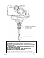
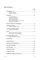
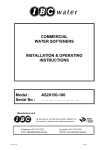
1
WATER SOFTENER
WITH 12 DAY SERIES
TIMER CONTROL
INSTALLATION & OPERATING
INSTRUCTIONS
Model :
Serial No :
AS0715-940
………………………..
Manufacturer and Supplier of
FILTRATION & WATER TREATMENT PRODUCTS
for commercial, industrial and residential application
Telephone: (07) 3219 2233
Email: [email protected]
AS0715-940
Facsimile: (07) 3219 2266
Website: www.ibcwater.com.au
Page 1
HARDNESS TEST
1.
Water to be tested should be taken from a tap after the water softener
2.
Measure 10ml of water into plastic bottle supplied (approximately 1/3 full)
3.
Add one Yes/No tablet to sample water, replace cap and shake until tablet
has completely dissolved.
(NOTE: do not handle Yes/No tablet with fingers)
4.
The final colour to be obtained for soft water is green. (Note: The shade of
green may vary.) If the colour turns red, the water is above 20 mg/l hardness,
therefore another regeneration is recommended.
5.
Rinse plastic bottle after each test has been completed.
6.
When used as above, the tablets change the colour from green to red at a
hardness of approximately 20ppm based on a sample volume of 10mls.
Other hardness test kits are available for more accurate testing eg.
Hardness Tablets
Directions:
Take a 50ml sample of water in a screw capped bottle. Add one (1)
tablet to sample, shake or crush to disintegrate. Repeat until last trace
of reddish tinge disappears. The final colour is usually blue but with
some water a greyish coloured end point is obtained.
Using 50ml sample Hardness ppm = (number of tablets x 40) - 20
LR (BW) Tablets
Directions:
Take a 100ml sample of water in a screw capped bottle. Add one (1)
tablet to sample, shake or crush to disintegrate. Repeat until last trace
of reddish tinge disappears. The final colour is usually blue but with
some water a greyish coloured end point is obtained.
Using 100ml sample Hardness ppm = (number tablets x 2) – 1
Contact IBC Water if further details are required.
AS0715-940
Page 2
WATER SOFTENER CALCULATIONS
MODEL AS0715-940
To ascertain DAYS between regeneration periods the following data or estimations are
required.
(Let N be the number of days to be calculated)
.1.
ð
Water Hardness in mg/l
.2.
ð
Water Softener Hardness Removal Capacity
from Table 1 in grams
call ð
call
ð
.3.
call
ð
H
C
Daily Water Usage in litres
ð
D
For household situations allow 250 litres per person per day.
CALCULATION
N
=
1000 x C
DxH
Select nearest lower whole number
If necessary consult your dealer or IBC Water Treatment for advice on setting up the
softener.
EXAMPLE
Household use for 2 people on 220 mg/l hard water using
Model AS0715 at 1050 grams capacity.
N
=
1000 x 1050
500 x 220
=
9.5 days
=
9 days
Note: Maximum number of days that can be selected is twelve (12).
AS0715-940
Page 3
WATER SOFTENER
PERFORMANCE DATA SHEET
Automatic
Model No.
AS0715-940
Capacity & Salt
Dosage
Minimum
Maximum
gram/kg
gram/kg
525/1
1050/3.6
Recommended
Maximum
Service Flow
Rate
Pipe Size
Resin
Volume
Approx.
Shipping
Weight
(kg)
Space
Required
Inlet
Outlet
Drain
Flow
LPM
mm
mm
Litres
Per Kg
metres
15
25
12
15
27
0.70
0.50
1.2
WxDxH
CABINET/BRINE CHAMBER: POLY MOULDED
Operating Pressure:
140 - 690 kPa
Temperature:
5o x 50oC
Electrical:
240V 50Hz 3 watts maximum
WARNING
A pressure reduction valve should be installed in areas of high water pressure (above 690kPa)
A water hammer arrestor should be installed if water hammer prevails.
Caution:
Do not use where water is microbiologically unsafe or with water of unknown quality.
FAILURE TO OBSERVE WARNINGS WILL VOID WARRANTY
AS0715-940
Page 4
INSTALLATION
OF
IBC CABINET WATER SOFTENER UNIT
FITTED WITH MODEL 255 VALVE/940 CONTROL
Check the equipment upon arrival for damage or shortages and report same to our Office or
Agent before starting.
Position the Softener Cabinet on a firm foundation, preferably concrete, with sufficient space
for operation and maintenance.
STEP 1
Connect inlet, outlet pipes and drain line to control valve as per Instruction
Booklet (page 5, figure 3).
Note: The softener is supplied with the Autotrol Series 156 Bypass Valve as
standard.
STEP 2
Remove lid from brine tank. Then connect brine overflow drain line to waste
trap.
STEP 3
Refer to Instruction Booklet for start up procedure (page 6 “Placing conditioner
into Service”).
STEP 4
Load recommended quantity of water softener salt into brine tank and replace
lid (refer to Table 3 “Brine Tank Salt Loading”).
Table 3
MODEL
AS0715-940
AS0715-940
RESIN LITRES
BRINE TANK - SALT
LOADING KG
15
50
Page 5
ASSEMBLE TOP STRAINER
TO VALVE BODY
PUSH AND TWIST
INTERNAL RISER PIPE
NOTE:
ON A NUMBER OF SOFTENER MODELS AND FILTERS IT IS
NECESSARY TO PACKAGE THE VALVE WITH THE TOP STRAINER
SUPPLIED LOOSE.
IT IS IMPORTANT THAT THIS STRAINER IS ASSEMBLED TO THE
VALVE DURING INSTALLATION.
THE LENGTH OF THE INTERNAL RISER PIPE IS FACTORY
ADJUSTED FOR THE TANK SIZE PROVIDED.
DO NOT SHORTEN THIS PIPE UNDER ANY CIRCUMSTANCES
AS0715-940
Page 6
940I Low Voltage Timer Control
The softener Control fitted is powered by a 240 to 12 Volt Transformer. The Transformer
plugs into a 10amp 240volt GPO and the transformer lead plugs into a socket located on the
back of the timer at the left-hand side. The Transformer is only suitable for indoor mounting.
Indicator Knob
Salt Dial
Clock Dial
Day Pins
(Do not rotate by hand)
Calendar Cap
Low Voltage Transformer
Only use the included transformer
for powering the Timer. Connect the
plug of the transformer cable to the
mating socket at the rear of the Timer
housing on the left-hand side.
When ordering spare parts: - Advise that the Timer is the low voltage model
AS0715-940
Page 7
Series 255 Valve / 940 Control
Water Conditioning Control System
Installation, Operating and Maintenance Manual
AS0715-940
Page 8
Table of Contents
Page
Introduction ……………………………………………………………… 10
Superior Design
Superior Operation
Installation ……………………………………………………………….. 10
Location Selection
Water Line Connection
Drain Line Connection
Brine Line Connection
Brine Tank Overflow Line Connection
Electrical Connection
Placing Conditioner into Operation …………………………………. 13
Adjustment of Timer ……………………………………………………. 14
Special Features of Timer
Adjustment of Brine Control ………………………………………….. 14
How to Set the Salt Dial
Service ……………………………………………………………………. 15
Removing the Timer Assembly
Removing the Valve Assembly
Preventative Maintenance …………………………………………..… 17
Injector Screen and Injector
Specifications …………………………………………………….……... 18
Pressure Graphs ……………………………………………………..…. 19
Control Valving identification…………………………………………. 20
Valve Disc Operation ………………………………………….……….. 20
Flow Diagrams …………………………………………………………... 21
Replacement Parts ……………………………………………………... 22
Trouble Shooting …………………………………………………….…. 26
Disinfection of Water Conditioners………………………………….. 27
AS0715-940
Page 9
Introduction
•
Direct acting system functions independently of
water pressure. No pistons or diaphragms that
require a minimum water pressure to operate.
•
Five-cycle operation provides for down flow
service, up flow backwash, down flow brining,
down flow slow and fast rinse. A sixth position is
included for timed refill of the brine tank.
•
Valve discs are held closed by water pressure
and therefore, are leak tight. The sealing forces
are increased as the water pressure is increased.
Valve seats are in a vertical position, which is
design position least vulnerable to plugging.
•
System operation cannot get out of phase or
sequence. The control always returns to a fixed
service position of regeneration regardless of
where in the regeneration cycle it was started.
•
Bypass (unconditioned) water is automatically
available during regeneration.
Thank you for purchasing a water conditioner system
featuring the Series 255 with a model 940 Control.
The Model 940 Control provides dependable time
clock based operation. The Series 255 valve
combines simplicity with reinforced NORYL *
construction to provide an uncommonly reliable
appliance. The inherent quality of the system means
a long life of efficient, trouble-free soft water. If
maintenance becomes necessary, the Series 255/940
Control offers a unique separation capability
illustrated in the Service section of this manual.
Superior design
•
Single synchronous electric motor provides all
the power for the clock and the operation of the
control.
•
Electrical wiring is factory assembled. System
cannot be connected incorrectly.
•
Program clock 940 (timer) and 960 Demand
system are interchangeable. Both units provide
guest regeneration capability.
•
•
System may be indexed manually with or
without power to any one of its service or
regeneration positions. Legend on timer faceplate
indicates control valve position.
No moving parts in water stream means no
close tolerance parts subject to fouling. Thus, the
system is especially effective on iron-bearing
water.
•
No dynamic seals that could cause leakage
through wear or fatigue.
•
Control accepts NORYL* or brass manifold or
modular bypass valve without modification,
offering complete versatility and easy plumbing
for any installation.
•
Brining control valve built into system
eliminates need for any brine valve.
•
Drain flow control is built into the valve to
control backwash and fast rinse flow rates.
•
NORYL is a trademark of GE Plastics.
Superior Operation
AS0715-940
Installation
All plumbing and electrical connections must conform
to local codes. Inspect the unit carefully for carrier
shortage or shipping damage.
Location Selection
•
•
•
Locate unit as close to a drain as possible
If supplementary water treating equipment is
required, make sure that adequate additional
space is available. Locate the brine tank in an
accessible place so that salt can easily be added.
Do not install any unit closer than 10ft (3m) of
piping between the outlet of the water conditioner
and the inlet of the water heater. Water heaters
can transmit heat back down the cold water pipe
into the control valve. Hot water can severely
damage the controller.
A 10ft (3m) total pipe run (including bends, elbows
etc) is a reasonable distance to prevent hot water
damage. A positive way to prevent hot water from
flowing from a heat source to the conditioner is to
install a check valve in the soft water piping from the
conditioner. If a check valve is installed, make sure
that the water-heating unit is equipped with a properly
rated temperature and pressure safety relief valve.
Always conform to local codes.
•
•
•
Do not locate the unit in an area where the temp
ever falls below 34ºF (1ºC) or over 120ºF (49ºC).
Do not install the unit near acid or acid fumes.
Do not expose the unit to petroleum products.
Page 10
Figure 1 - Control
Bypass Valve (optional)
Air Check
Brine Tube Fitting
Connection 1/4"
Inlet Connection 3/4" or 1" NPT or BSPT
Drain Connection 3/8" or 1/2" NPT or BSPT
Outlet Connection 3/4" or 1" NPT or
Tank Tread 2-1/2" - 8 male NPSM
Figure 2 - Tank Adaptor
AS0715-940
Page 11
Water Line Connection
A bypass valve system must be installed to provide
for occasions when the water conditioner must is bypassed for hard water or for servicing. The most
common bypass systems are the Autotrol Series 156
Bypass Valve, Figure 3, and plumbed-in globe
valves, Figure 4. Though both are similar in function,
the Autotrol Bypass offers simplicity and ease of
operation.
Not In Bypass
In Bypass
Figure 3 - Autotrol Series 156 Bypass Valve
Not In Bypass
In Bypass
Figure 5 - Air Gap Installation
Caution
Never connect the drain line into a drain,
sewer line or trap. Always allow an air gap
between the drain line and the wastewater
to prevent the possibility of sewage being
back-siphoned into the conditioner.
The ideal location for the unit is above and not more
than 20ft (6.1m) from the drain. For such installations,
using the appropriate adaptor fitting (not supplied),
connect 1/2 in (1.3cm) plastic tubing to the drain line
connection located at the rear of the control.
If the unit is located more than 20ft (6.1m) from the
drain, use 3/4in (1.9cm) tubing for runs up to 40ft
(12.2m). You may elevate the line up to 6ft (1.8m)
providing the run does not exceed 15ft (4.6m) and the
water pressure at the conditioner is not less than
40psi (280kPa). You may elevate an additional 2ft
(61cm) for each additional 10psi (70kPa) of water
pressure. When the drain line is elevated and empties
into a drain which is below the level of the control
valve, form a 7 inch (17cm) loop at the drain end of
the line so that the bottom of the loop is level with the
drain line connection. This provides an adequate
siphon trap. If the drain empties into an overhead
sewer line, a sink-type trap must be used.
Note: The above instructions reflect standard
commercial practices. Local codes may require
different installation procedures.
Brine Line Connection
Install the brine tube and connect to the fitting
connection located on the air check on the tank
adaptor module, see Figure 2.
Figure 4 - Typical Globe Valve Bypass
System
Drain Line Connection
The drain line discharges water and brine during the
regeneration cycles. Typically, the line drains into a
floor drain or laundry tube. Plumb the drain line
according to local codes, leaving a one or two inch air
gap between the end of the drain line and the opening, Figure 5.
AS0715-940
Note: Make sure that all fittings and connections are
tight so that premature checking does not take place.
Premature checking occurs when the ball in the air
check falls to the bottom before all brine is drawn out
of the brine tank. Refer to the Troubleshooting
section in this manual for additional information.
Brine Tank Overflow Line Connection
In the event of a malfunction, the tank overflow
connection directs overflow to the drain instead of
spilling on the floor where it could cause water
damage. Complete the following steps to connect the
overflow fitting to the brine tank:
1. Locate the fitting hole on the side of the brine
tank.
Page 12
2. Insert the overflow fitting (not supplied) into the
tank and tighten with the plastic thumbnut and
gasket as illustrated in Figure 6.
3. Attache a length of 1/2in (1.3cm) tubing (not
supplied) to the fitting and run to the drain.
Note: Don not elevate the overflow line higher than
3in (7.6cm) below the bottom of the overflow fitting.
Do not tie into the drain line of the control unit. The
overflow line must be a direct, separate line from the
overflow fitting to the drain, sewer or tube. Allow an
air gap as in the drain line connection, Figure 5.
If the water supply valve is opened too rapidly
or too far, resin may be lost. In the BACKWASH
position, you should hear air escaping slowly
from the drain line.
3. When all the air is purged from the tank (water
begins to flow steadily from the drain), slowly
open the main supply valve all the way. Allow the
water to run into the drain until the water appears
clear. Turn off the water supply and wait for about
five minutes to allow all trapped air to escape
from the tank.
4. Add water to the brine tank (initial fill). With a
bucket or hose, add approximately 4 gallons (15
litres) of water to the brine tank.
Figure 6 - Overflow Line Connection
Electrical Connection
Remove the twist tie from the power cord and extend
the cord to its full length. Make the power source
matches the electrical rating of the control. Be sure
the outlet you select is not controlled by a wall switch.
Figure 7
Air Check
Placing Conditioner into Operation
After the water conditioning system is physically
installed, we recommend that the conditioner be
disinfected before it is used to treat potable water.
Refer to the Disinfection of Water Conditioners
section in this manual. Complete the following steps
to place the conditioner into service.
1. Grasp the indicator knob on the timer (Figure 8)
and rotate it counterclockwise about 45° to the
back- wash position. You may find it helpful to
remove the rear cover (Figure 10) and rotate the
camshaft counterclockwise at the same time.
2. Fill the mineral tank with water by turning the
water supply off and placing the bypass valve(s)
into the "not in bypass" position. Open the water
supply valve very slowly to approximately the 1/4
open position.
Caution
AS0715-940
5. To start up the unit: make sure the water supply
valve is in the full open position. Carefully rotate
the indicator knob, Figure 8, counterclockwise
until the indicator points directly to the centre of
the REFILL position and hold there until the air
check (Figure 7), fills with water and water flows
through the brine line into the brine tank. Do not
run the water into the brine tank for more than
one or two minutes.
Rotate the indicator knob counterclockwise until
the indicator points to the centre of the BRINE/
SLOW RINSE position.
Check the water is being drawn from the brine
tank. The water level in the brine tank will recede
very slowly. Observe the water level for at least
three minutes. If the water level does not recede,
if it goes up, or if air enters the air check sight
glass and the ball falls and seats, refer to the
Troubleshooting section in this manual.
Page 13
Finally, rotate the indicator knob counterclockwise until the indicator points to
REGENERATION COMPLETE. Run water from
a nearby cold-water faucet until the water is clear
and soft.
Adjustment of Timer
Salt Dial
Indicator Knob
Clock Dial
Special Features of Timer
Guest Cycle. When abnormally high water usage
exhausts the water conditioner's capacity ahead of
schedule, an extra regeneration can be achieved by
turning the indicator knob counterclockwise to
START, Figure 8. It will take a few minutes for regeneration to begin. The normal regeneration schedule
will not be disrupted.
Manual Regeneration. Electricity is used only to run
the timer and to rotate the camshaft. All other
functions are operated by water pressure. Therefore,
in the event of a power outage, all the various
regeneration positions may be dialled manually by
rotating the indicator knob counterclockwise.
Manual time cycle:
BACKWASH……………………..14 minutes
BRINE AND SLOW RINSE……. 52 minutes
FAST RINSE…………………….. 6 minutes
REFILL…………………………… Read time
Off Salt Dial
Adjustment of Brine control
Day Pins
(Do not rotate by hand)
Calendar Cap
1. Set days of regeneration (Figure 8).
• Pull all day pins outward (away from control)
• Depress day pin(s) at day(s) for which
regeneration is desired.
All models may be tuned to produce maximum to
minimum conditioning capacities by adjusting the Salt
Dial (Figure 9). The Salt Dial controls the amount of
salt used per regeneration. When desired, the
minimum setting may be used if the frequency of
regeneration is increased to compensate for the lower
regenerated conditioning capacity.
Salt Dial
Note: The NEXT DAY day pin is noted on the timer
face. Depressing this pin will insure regeneration the
next day at approximately 2:00am. Since the calendar
cap progresses clockwise, depressing the day pin
immediately counterclockwise will insure regeneration
the following day at 2:00 am. This progression is
noted on the timer face as "FUTURE DAYS".
2. Set the time of day.
• Rotate Clock Dial until the pointer is directed
at the current time.
Note: With the time of day properly set, the
conditioner will regenerate at about 2:00 am. If you
prefer to have the unit regenerate at an earlier or later
time, simply set the current time-of-day accordingly.
(e.g., To have the unit REGENERATE at 4:00am - 2
hours later - set the clock 2 hours later than the actual
time).
Note: Do not rotate the Calendar Cap by hand; the
clock dial indexes it daily. To manually index the
Calendar Cap, rotate the Clock Dial clockwise one
complete turn for every day to be indexed.
AS0715-940
Indicator Knob
How to Set the Salt Dial
With the indicator knob in the REGENERATION
COM-PLETE position (Figure 8), rotate the Salt Dial
counter-clockwise at least one full turn to cancel out
the previous setting. A light clicking will be replaced
by a heavier clicking when the previous setting is
cancelled. Then, rotate the Salt Dial to the proper salt
setting.
The numbers on the dial are "minutes" of water flow
to the brine tank. When using the .4 gpm Brine Refill
Control, each minute corresponds to 1.2 pounds of
salt. The size of the brine control is embossed on the
refill cap. The embossed number corresponds to the
gpm flow control. Example: 33 corresponds to .33
Page 14
gpm flow control. One gallon of water will dissolve 3.0
pounds of salt.
Figure 10
To calculate the time for brine refill, it is necessary to
determine the needed pounds of salt and divide that
number by three (3 pounds per gallon) and also divide
by the flow control gpm. The result is the time setting
in minutes for brine refill. Be sure to round off times to
the nearest minute
Reference Table 1 for common settings.
MODEL AS0715-940 WATER SOFTENER
HARDNESS REMOVAL
CAPACITY INGRAMS
SALT USAGE
IN KILOGRAMS
SALT DIAL SETTING
TIME IN MINUTES
525 (MIN)
1.0
3
700
1.6
4
825
2.2
6
1050 (MAX)
3.6
9
NOTE: - THIS SOFTENER IS FITTED WITH THE
0.33 G.P.M BRINE REFILL CONTROL
Service
Removing the Timer Assembly
Complete the following steps to remove the timer
assembly for servicing:
1. Unplug the power cord.
2. Remove the rear cover by pushing back on the
tab provided on the cover with your thumb, Figure
10. Next, lift the cover off the valve.
AS0715-940
3. To remove the camshaft (or reinstall it), the rib on
the shaft must be pointing straight up. This occurs
when the indicator knob is rotated to the refill
position. Press down on the back of the camshaft
to disengage it from the rear "hoop" of the top
plate, Figure 11.
Page 15
6. To replace the timer, reverse the above
Procedure.
Figure 11
4. Slide the camshaft back, disengage it from the
timer, Figure 12.
Note: The camshaft and the timer indicator knob
need to be positioned correctly before the
camshaft can be installed. Rotate the camshaft
such that the locating rib is pointing straight up.
The timer indicator knob must be in the REFILL
position when installing the camshaft. Slide the
camshaft into the timer. It may be necessary to
rock the timer slightly to key the camshaft into the
timer. When the camshaft is slid into place, lift he
back of the camshaft up while rotating the
indicator knob to seat the camshaft in the top
plate "hoop".
Removing the Valve Assembly
Complete the following steps to remove the valve
assembly:
1. Unplug the power cord.
2. Shut off the water supply or place in bypass
3. Relieve the system pressure by opening the rinse
drain valve (the fifth valve back from the timer)
with a screwdriver, Figure 14.
Figure 12
5. Lift the timer off the valve, Figure 13.
Figure 14
4. Remove the locking bar screw, Figure 15.
Figure 13
AS0715-940
Page 16
require more frequent injector and screen servicing.
Refer to Figure 17 and complete the following steps
to clean the injector screen and injector:
1. Unplug the power cord.
2. Shut off the water supply or put the bypassvalve(s) into the bypass position and remove the
rear cover, Figure 10.
Figure 15
3. Relieve system pressure by opening the rinse
drain valve (the fifth valve back from the control)
with a screwdriver, Figure 11.
4. Using a blade screwdriver, unscrew and remove
the injector screen and injector cap.
5. Apply downward hand pressure on the valve and
remove the locking bar, Figure 16.
5. Clean screen with a fine brush. Flush with water
until clean.
6. Using a needle-nose pliers, pull the injector
straight out.
7. Flush water into the injector screen recess of the
valve body to flush debris out through the injector
recess.
8. Clean and flush the injector. Lubricate the o-rings
on the injector, injector cap and injector screen
with silicone lubricant.
Figure 16
6. Using the rocking motion, lift the valve from the
tank adaptor, Figure 16. If the o-ring seals come
off with the valve put them back into the tank
adaptor sockets. Lubricate the o-rings with
silicone lubricant.
Note: Petroleum based lubricants will damage
the
Plastic valve and o-rings.
Reverse the procedure to replace the valves.
Figure 17
Preventative Maintenance
Injector Screen and Injector
The injector is the component which creates the
vacuum necessary to draw the brine into the water
conditioner. Clean the injector and injector screen at
least once a year in order to maintain proper
operation of the conditioner. Some locations may
AS0715-940
9. Reinstall the injector (small and first), injector cap
and injector screen.
Caution
Do not overtighten the plastic cap. Seat he
Page 17
cap lightly into position. Overtightening
can
cause breakage of the plastic cap which may
not be evident immediately
11. Reconnect electric power, and reset the time of
day.
10. Slowly open the water supply valve or return the
bypass valve(s) to the not in bypass" position.
Hydrostatic Test Pressure ……………………………………………………………………………. 300 psi
(2069kPa)
Working Pressure ………………………………………….. 20 to 127 psi (138 to 876 kPa), 100 psi max in
Canada
Voltage ……………………………….. 24V 50 Hz, 24V 60 Hz, 100V 50 Hz, 100V 60 Hz, 230V 50 Hz, 115V 60
Hz
Current ……………………………………………………………………………………………………………….. 50
mA
Operating Temperature …………………………………………………………………..… 34°F (1°C) to 120°F
(49°C)
Humidity ………………………………………………………………...…………….10% to 100%, condensing
allowed
Pressure Tank Thread ………………………………………………………………………………… 2 1/2 in - 8
NPSM
Brine Line Thread ………………………………………………………………………………………... 1/4 in NPT
male
Distributor Tube Diameter Required …………………………………………………………. 13/16 in O.D. (20.6
mm)
AS0715-940
Page 18
Distributor Tube Length …………………………………………... 1 1/4 in (31.8mm) higher than top of mineral
tank
Standard Manifold Connection ……………………… 3/4 in NPT inlet-outlet, 1/2 in NPT drain in NORYL
manifold,
3/8 in NPT drain in brass
manifold
Optional Manifold Connections …………… 1 in NPT inlet-outlet, 1/2 in NPT drain; 3/4 in BSPT inlet-outlet, 3/8
in
BSPT drain; 1 in BSPT inlet-outlet, 1/2 in. BSPT
drain
Optional Bypass Valve ……………….. 3/4 in (19.1mm) or 1 in (25.4mm) copper tailpiece, 1/2 in NPT male
drain
Valve Module, Tank Adaptor, Optional Bypass Valve …………………………………………… Reinforced
NORYL
Inlet-Outlet Manifold ………………………………………………………………………... Brass or reinforced
NORYL
Rubber Parts ………………………………………………………………………. Compounded for cold water
service
Injector size "A" White …………………… Nozzle 0.042 in (1.1 mm) diameter, Throat 0.089 in (2.3 mm)
diameter
Injector size "B" Blue …………………….. Nozzle 0.052 in (1.3 mm) diameter, Throat 0.099 in (2.5 mm)
diameter
Injector size "C" Red …………………… Nozzle 0.059 in (1.51 mm) diameter, Throat 0.099 in (2.5 mm)
diameter
Backwash Controllers Available for ………………………………………………………... 6, 7, 8, 9, 10, 12, 13, 14
in
(15.2, 17.8, 20.3, 22.9, 25.4, 30.5, 33.0, 35.6 cm) diameter mineral
tanks
All sized to flow 4.5 gpm/sq ft (183 l/min/m2) of bed
area
Pressure Graphs
AS0715-940
Page 19
Control Valving Identification
AS0715-940
Valve Disc Operation
Page 20
Flow Diagrams
AS0715-940
Page 21
AS0715-940
Page 22
Replacement Parts
940 Timer
Code
Part No. Description
Qty
1
1000855 Backplate
1
2
1000879 Gear Support Plate, 12 - Hour Clock
1
3
1000881 Timer Cover, English Standard 1
4
1000887 7 - Day Calendar Cap Assembly
1
5
1000888 12 - day Calendar Cap Assembly
1
6
1000877 Main Drive Stack
1
7
1000848 Knob
1
8
1000857 Salt Dial
1
9
1000847 Salt Gear
1
10
Main Drive Gear
1
Standard Cycle
Water Saver, Economy Cycle
Extra Salt & Long Rinse, Long Rinse Cycle
Adj. Backwash/Standard Cycle
Adj. Backwash/Extra Salt Long Rinse,
Long Cycle
1000905 3 Cycle/Adj. Backwash
Code
Part No. Description
Qty
12
1000841 Clutch Gear
1
13
1007483 Wire Nut
1
14
1000833 Gear
1
15
1000832 Gear
1
16
1000858 Geneva/Clock
1
17
1000844 Geneva/Drive Gear
1
18
Power Cord
1
1000821 North America (Flat 2-Wire)
1007495 Italy (CEI 23-16/VII)
25A292 Continental Europe (CEE 7/7)
25A303 United Kingdom (AS 3112)
1007496 Australia (AS 3112)
25A555-001Japan (JIS 8303)
1000822 Lamp Cord, Low Voltage (24V)
25A394 North America (US - NEMA 5-15P)
(Canada C22.2 No. 42) (Flat 3-Wire)
*
1000939 Retainer, Calendar Cap
( *Not Shown)
1000900
1000901
1000902
1000903
1000904
11
1000802
1000803
1000804
1000805
1000806
1000807
AS0715-940
Motor Option
24V 50 Hz
24V 60 Hz
110V 50 Hz
100V 60 Hz
230V 50 Hz
115V 60 Hz
1
Page 23
AS0715-940
Page 24
Valve Body and Tank Adaptor Module
AS0715-940
Page 25
Code
Part No. Description
1
1000238 Valve Assy. w/o Flow Controls 1
2
1000824 Camshaft, Std, One-Piece
1
3
1000827 Valve Cover, Black
1
4
Brine Refill Flow Control Assy. :
1000221 .14 GPM
1000222 .33 GPM
1000223 .40 GPM
1
5
1000226 Screen/Cap Assy. With O-ring
1
6
Backwash Control Assy. With
O-rings:
No. 7 for 7 in Diameter Tank
No. 8 for 8 in Diameter Tank
No. 9 for 9 in Diameter Tank
No. 10 for 10 in Diameter Tank
No. 12 for 12 in Diameter Tank
No. 13 for 13 in Diameter Tank
No. 14 for 14 in Diameter Tank
1
1000209
1000210
1000211
1000212
1000213
1000214
1000215
Qty
Part No. Description
Qty
10
1033784 Tank Adaptor Assy.
1
11
1032416 Air Check Ass.
1
12
1010429 O-ring, 3-1/8x3-1/2x3/16 BN
1
13
1010428 O-ring, 3/4x1x1/8 EP
1
14
Locking Bar:
1031402 English Language
1
15
1006093 Screw, No. 8x9/16 in1
16
1001580 Spring, Valve Discs
17
*
7
1030502 Ball, Flow Control
1
8
Injector Assy. With O-rings
1032970 "A" Injector - White
1032971 "B" Injector - Blue
1032972 "C" Injector - Red
1
9
Injector Cap With O-rings
1000217 "A" Cap
1000218 "B" Cap
1000219 "C" Cap
1
AS0715-940
Code
18
19
*
20
9
Kits:
1033066 New to Old Air Check Adaptor
1000250 Valve Discs Replacement
(*Not Shown)
1001404 O-ring Group: Tank Adaptor
1040459 O-ring Group: Piping Boss
1000252 Severe Service Valve Discs
(*Not Shown)
1041010 Optional Riser Insert 13/16
Page 26
Bypass Valve and Piping Boss
Code
Part No. Description
Qty
1
1040769 Bypass Body Assy
1
2
1040524 Installation Kit:
3
1001606
1001670
1001608
1001609
1001613
1001614
1001615
1001769
1001603
1001604
1001605
1001611
1001610
1001612
Code
Part No. Description
Qty
Piping Boss
AS0715-940
3/4 in Copper Tube Adaptor Kit 1
1 in Copper Tube Adaptor Kit
22mm Copper Tube Adaptor Kit
28mmCopper Tube Adaptor Kit 1
3/4 in CPVC Tube Adaptor Kit
1 in CPVC Tube Adaptor Kit
25mm CPVC Tube Adaptor Kit 1
3/4 in NPT Plastics Pipe Kit
1 in NPT Plastics Pipe Kit
3/4 in BSPT Plastic Pipe Adaptor Kit
1 in BSPT Plastic Pipe Adaptor Kit
3/4 in BSPT Brass Pipe Adaptor Kit
1 in NPT Brass Pipe Adaptor Kit
1 in BSPT Brass Pipe Adaptor Kit
4
Kit
1040277
1040278
1040281
1040282
1040279
1040280
1040283
1040284
5
1040339 Piping Boss Installation Kit
1
1
1
1
1
1
1
1
1
1
1
Piping Boss (Includes Hardware)
3/4 in NPT, Brass, 3/8 in NPT Drain
1 in NPT, Brass, 1/2 in NPT Drain
3/4 in BSPT, Brass, 3/8 in BSPT Drain
1 in BSPT, Brass, 1/2 in BSPT Drain
3/4 in NPT, Noryl, 1/2 in NPT Drain
1 in NPT, Noryl, 1/2 in NPT Drain
3/4 in BSPT, Noryl, 1/2 in BSPT Drain
1 in NPT, Noryl, 1/2 in NPT Drain
Page 27
Troubleshooting
The technology upon which the Series 255/940
control is based, is well established and proven in
service over many years. However, should a problem
or question arise regarding the operation of the
system, the control can be very easily serviced. The
control module can be quickly replaced or
adjustments can be made at the installation. For parts
mentioned, refer to exploded views in the
Replacement Parts section of this manual.
Problem
IMPORTANT: Service procedures that require the
water pressure to be removed from the system are
marked with a ! after the possible cause. To remove
water pressure from the system, put the bypass valve
or three-valve bypass into the bypass position and
open the Rinse Drain Valve (the fifth valve back from
the control) with a screwdriver, Figure 11. Restore
system water pressure when the service work is
completed.
Cause
Solution
1. Control will not
regenerate automatically
a. Electric cord unplugged
b. Defective Timer motor
c. Day pins not down on calendar
cap.
d. Binding in gear train of timer
a. Connect power
b. Replace motor
c. Depress pins for days regeneration
required
d. Replace timer
2. Control regenerates at
Wrong time of day
a. timer set incorrectly.
a. Correct setting according to
Instructions.
3. Control will not draw
Brine.
a. Low water pressure.
a. Water pressure must be 20 psi
minimum.
b. Remove restriction.
c. Clean injector and screen.
d. Replace injector cap.
e. Flush out foreign matter holding disc(s)
open by manually operating valve
stem(s). Replace if needed.
f. Put control momentarily into brine refill.
replace or repair air check if needed.
Refer to Brine Line Connection.
4. Brine tank overflow.
b.
c.
d.
e.
Restricted drain line.
Injector plugged. !
Defective injector. !
Valve disc 2 and/or 3 not closed.
f.
Air check prematurely closed.
a. Brine valve disc1 being held open
By foreign matter.
b. Uncontrolled brine refill flow rate.
c.
Valve disc 2 and/or 3 not closed
During brine draw causing brine
refill
d. Air leak in brine line air check.
e. Improper drain control for injector.
5. System using more or
less salt than salt control
Is set for.
a. Inaccurate setting.
b. Foreign matter in controller
Causing incorrect flow rates.
c. Defective controller. !
AS0715-940
a. Flush out foreign matter holding disc
open by manually operating valve stem.
b. Remove and clean brine refill flow
control.
c. Flush out foreign matter holding disc(s)
open by manually operating valve
stem(s).
d. Check all connections in brine line for
leaks. Refer to Brine Line Connection.
e. Too small of a drain control with a "B"
or "C" injector will reduce draw rates.
Reference Pressure Graphs.
a. Make correct setting
b. Remove salt controller and flush out
foreign matter. Manually position
control to brine draw to clean
controller. After so doing, position
control to "brine/slow rinse" to remove
brine from tank.
c. Replace defective part.
Page 28
AS0715-940
Page 29
6. Intermittent or irregular
brine draw .
a. Low water pressure.
a. Water pressure must be 20 psi
Minimum.
b. Replace both injector and injector cap.
b. Defective Injector. !
7. No conditioned water
After regeneration.
a. Unit did not regenerate
b. No salt in brine tank
c. Plugged injector.
d. Air check prematurely closed.
a. Check for power.
b. Add salt to brine tank.
c. Remove injector and injector screen,
Flush with water.
d. Put control momentarily into brine refill
To free air check. Replace or repair air
check if needed. Refer to brine line
connection.
8. Control backwashes at
Excessively low or high
Rate.
a. Incorrect back wash controller. !
b. Foreign matter effecting controller
Operation. !
a. Replace with correct size controller.
b. Remove and clean controller seat and
Ball.
9. Flowing or dripping
Water at drain or brine
Line after regeneration.
a. Drain valve (5 or 6) or brine valve
(1) held open by foreign matter or
particle.
b. Weak valve stem return spring on
Top plate.
a. Manually operate valve stem to flush
Away obstruction.
a. Improper regeneration.
a. Repeat regeneration making certain
Correct salt usage is used.
b. Replace o-ring.
c. Replace o-ring.
d. Replace defective part.
10. Hard water leakage
During service.
b. Leaking external bypass valve.
c. O-ring around riser tube
Damaged.
d. Leaking past bypass valve disc.
b. Replace spring.
Disinfection of Water Conditioners
The construction materials of the water conditioner
system do not support bacterial growth or
contaminated the water supply. However, we
recommend that the conditioners be disinfected after
installation and before the conditioners are used to
treat potable water. In addition, a conditioner can
become fouled with organic matter during normal
usage or with bacteria from the water supply. Periodic
disinfection is recommended for all conditioners. Use
one of the following methods of disinfection based on
operating conditions, style of conditioner, type of ion
exchange, and disinfectant available.
Sodium Hypochlorite
Sodium Hypochlorite, 5.25% solutions, can be used
with polystyrene resin, synthetic gel zeolite,
greensand, and bentonites and are available under
trade names such as Chlorox, Linco, Bo Peep, White
Sail and Eagle Brand Bleach. Adjust the dosage if
stronger commercial solutions are used.
The recommended dosage for 5.25% solution is:
• Polystyrene resin: 1.2 fluid ounces per cubic foot.
• Non-resinous exchangers: 0.8 fluid ounces per
cubic foot.
AS0715-940
Complete the following steps to disinfect the
conditioner: Add the sodium hypochlorite solution to
the brine well of the brine tank. Make sure that the
brine tank has water init so the solution is carried into
the conditioner. Proceed with normal regeneration.
Refer to the Manual Regeneration section for this
manual.
Calcium Hypochlorite
Calcium Hypochlorite, 70% available chlorine, is
available in several forms including tablets and
granules. These solid materials can be used directly
without dissolving before application.
The recommended dosage for Calcium Hypochlorite
is two grains (approx. 0.1 ounce) per cubic foot.
Complete the following steps to disinfect the
conditioner: Add the Calcium Hypochlorite to the
brine well of the brine tank. Make sure that he brine
tank has water in it so the solution is carried into the
conditioner. Proceed with normal regeneration. Refer
to the Manual Regeneration section of this manual.
Page 30