1
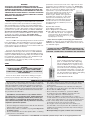
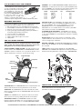
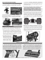
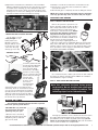
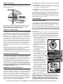
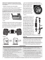
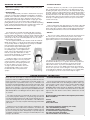
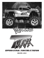
OPERATING INSTRUCTIONS
MODEL 4910
WARNING!
FOLLOW ALL THE INSTRUCTIONS IN THIS AND THE
ACCOMPANYING MANUALS IN ORDER TO AVOID SERIOUS
DAMAGE TO YOUR MODEL. IF THESE INSTRUCTIONS ARE
NOT FOLLOWED, THE RESULTING DAMAGE WILL BE CONSIDERED ABUSE AND/OR NEGLECT, THEREBY RELEASING
BOTH TRAXXAS AND YOUR DEALER FROM ANY FURTHER
WARRANTY RESPONSIBILITY.
INTRODUCTION
Thank you for purchasing the Traxxas T-Maxx. This sophisticated truck incorporates many special features including 4 wheel
drive, forward and reverse operation, two speed forward and two
speed reverse transmission, the EZ-Start™ electric starter, and the
reliable TRX Pro.15 engine. This manual contains the instructions
you will need to operate, and maintain your T-Maxx. Look over
the manual and examine the T-Maxx carefully before running
it. If for some reason you think the T-Maxx is not what you wanted, then do not continue any further. Your hobby dealer
absolutely cannot accept a T-Maxx for return or exchange
after it has been run.
Please read ALL of the Operating Instructions and Precautions
before attempting to drive the T-Maxx. Even if you are an experienced R/C enthusiast, continue reading to learn about T-Maxx’s
unique features. Pay special attention to the mechanical and safety precautions outlined in the manual.
If you have any questions about your new model, feel free to
call Traxxas’ technical support line toll-free at 1-888-TRAXXAS
(1-888-872-9927) Outside the U.S. call 972-265-8000. Technical
support is available Monday through Friday, from 8:30am to 9:00
pm central Time. Technical assistance is also available through
our website at www.traxxas.com (E-mail us at
[email protected]). We hope that you will enjoy many hours
of fun with your new T-Maxx.
FUEL
CAUTION:
ALWAYS FOLLOW THE PRECAUTIONS PRINTED ON
THE CONTAINER OF FUEL. KEEP IT AWAY FROM
FLAMES AND CHILDREN. THE MIXTURE IS FLAMMABLE
AND POISONOUS.
Fuel is the most critical component for making your engine
perform properly. Improper fuels will cause hard starting, poor
performance, and excessive wear on the engine. For the best
performance from your TRX Pro.15 engine, use Traxxas Top
Fuel™. Traxxas Top Fuel is the only model engine racing fuel
which exceeds all of the Traxxas engine warranty
requirements, is specially formulated to resist
heat, and is guaranteed to provide the best
performance and longest life from your
Traxxas engine. Traxxas cannot guarantee
the quality and consistency of other manufacturers’ fuels. If Traxxas Top Fuel is not
available from your hobby dealer, the fuels
listed below have been tested by Traxxas
and determined to be satisfactory for use in
the TRX Pro.15.
Dynamite Blue Thunder
Power Master Formula 16
Byron’s Originals Race 1000/2000
Morgan’s Omega (Omega fuel is an airplane
fuel which may be used. The higher oil
content however, will not deliver the same
performance and tuning ease as a good,
special-purpose car fuel)
Some fuels are capable of destroying your TRX Pro.15
engine! If you must use a fuel other than those listed, contact
TRAXXAS, at 1-888-TRAXXAS, to find out if the fuel is safe for
use with TRX engines.
CAUTION:
ALWAYS FOLLOW THE PRECAUTIONS PRINTED ON THE
CONTAINER OF FUEL. KEEP IT AWAY FROM FLAMES AND
CHILDREN. THE MIXTURE IS FLAMMABLE AND POISONOUS.
FUEL BOTTLE
Fuel is usually purchased by the gallon or
quart, so a smaller bottle with a dispensing
tube is required to fill the fuel tank. The fuel
tank in the T-Maxx has a capacity of 125cc.
The fuel bottle should always be capped to
prevent the fuel from evaporating and becoming contaminated with debris or moisture. The
alcohol and nitro contents of the fuel will evaporate, thus upsetting the fuel balance and spoiling
the fuel. Do not use old or dirty fuel!
Traxxas #5050-Fuel Bottle
PERSONAL SAFETY PRECAUTIONS
Every precaution outlined in this manual needs to be followed
to help ensure safe operation. Operate your T-Maxx sensibly and
with care and it will be exciting, safe, and fun for you and your
spectators. Failure to operate your T-Maxx in a safe and responsible manner could result in property damage and serious injury.
You alone must see to it that the instructions are followed and
the precautions are adhered to.
The T-Maxx is not intended for use by children without
the supervision of a responsible adult. Traxxas shall not be
liable for any loss or damages, whether direct, indirect, special, incidental, or consequential, arising from the use, misuse, or abuse of this product and any chemical or accessory
required to operate this product.
• The fuel is dangerous and poisonous. Follow all of the directions
and precautions on the fuel container.
• The fuel can look like a cool drink to a young child. Keep it out
of children’s reach.
• The fuel is flammable. Do not allow sparks, flame, or smoking
in the presence of model fuel.
2
• The engine emits poisonous carbon monoxide gas. Always run
the model in a well-ventilated area. Never attempt to run the
engine indoors.
• The engine and exhaust become extremely hot during use.
Be careful not to touch these parts, especially when refueling.
• Do not drive the T-Maxx at night.
• Never, under any circumstances, operate the T-Maxx
in crowds of people. The T-Maxx is very fast and could
cause injury if allowed to collide with anyone.
• Because the T-Maxx is controlled by radio, it is subject
to radio interference from many sources that are beyond your
control. Since radio interference can cause momentary losses
of radio control, always allow a safety margin in all directions
around the model in order to prevent collisions.
• The engine can be very loud. If the noise makes you
uncomfortable, wear ear protection. Be considerate of your
neighbors by not running your model early in the morning or
late in the evening.
• Most importantly, use good, common sense at all times.
Contact Traxxas for assistance: 1-888-TRAXXAS. 972-265-8000 (outside USA). E-mail us at [email protected]
7.2v BATTERY PACK AND CHARGER
The EZ-Start™ electric starter requires a
7.2 volt rechargeable nicad battery pack.
The battery pack straps to the bottom
of the EZ-Start™ control box with
the supplied tie wraps. The battery
pack must be fully charged in order
to start the engine. It can be
recharged with an overnight “wall
charger”, a peak-detecting charger, or
a 15-minute quick charger. All are available from a hobby dealer.
REQUIRED EQUIPMENT
To operate the T-Maxx, you will need these additional items. All of
these items should be available from your hobby shop.
1. “AA” size batteries for your transmitter(8) and receiver(4)
2. Small Phillips head and flat screwdrivers (for adjustments)
3. After-run oil (to protect the engine from corrosion)
4. Spare glow plugs (standard plug, Traxxas part #3230; or
heavy-duty plug, Traxxas part #3231).
5. In-line fuel filter (recommended)
6. Spare fuel line (recommended)
7. Hobby-quality, thin CA glue for the tires
8. Hobby knife
CHANNEL - The 27 MHZ FREQUENCY BAND is divided into 6
CHANNELS, so that up to six cars can be operated simultaneously.
These CHANNELS are referred to by their number and flag color.
The chart below lists the channels and their flag colors.
27MHZ
26.995
27.045
27.095
27.145
27.195
27.255
FLAG COLOR
BROWN
RED
ORANGE
YELLOW
GREEN
BLUE
CH#
1
2
3
4
5
6
TRAXXAS PART#
2031
2032
2033
2034
2035
2036
CRYSTAL (X-TAL) - The CRYSTAL is the plug-in device that
determines which channel the RADIO SYSTEM will operate on.
For each CHANNEL, there are two CRYSTALS, one for the
RECEIVER and one for the TRANSMITTER. Of those two
CRYSTALS, the one marked with the lower number (.455 MHZ
lower) must be inserted in the RECEIVER.
CLEARING YOUR FREQUENCY - CLEARING your frequency
means checking to be sure no one else in the area is operating
on the same CHANNEL. You should always do this before operating
your model.
THE TQ-3 RADIO SYSTEM
NICAD (Ni-Cd) - These terms stand for rechargeable, nickel
cadmium batteries. These batteries are most economical and
can be recharged up to 500 times.
The T-Maxx model 4910 is equipped with the 3-channel TQ-3
radio system. The following radio system terms will be used
throughout the rest of these operating instructions.
NEUTRAL POSITION - The NEUTRAL POSITION is the standing
position that the SERVOS seek when the TRANSMITTER controls
are at neutral.
THREE-CHANNEL RADIO SYSTEM - The radio system in your
model consists of the RECEIVER, the TRANSMITTER, and the
SERVOS. It has three channels, one to operate the throttle, one to
shift the transmission, and one to operate the steering.
TRIM - TRIM is the fine-tuning adjustment of the NEUTRAL
POSITION of the SERVOS. This adjustment is made by turning the
throttle and steering trim knobs on the face of the TRANSMITTER.
Antenna
Throttle Neutral Adjust
Steering Wheel
Throttle Trim
Steering Trim
Reverse Shift
Forward Shift
Throttle Trigger
Power Switch
Battery
Compartment
Power Indicator
Servo Reversing Switches
TRANSMITTER - The TRANSMITTER is the hand-held radio unit
which sends throttle and steering instructions to the model.
RECEIVER - The RECEIVER is the radio unit inside the model
which receives signals from the TRANSMITTER and relays them
to the SERVOS.
INSTALLING TRANSMITTER BATTERIES
Install 8 “AA” batteries into the bottom of the
transmitter as shown in the drawing.
SERVO - The SERVOS are the small motor units in the model
which operate the steering, shifting and throttle mechanisms.
FREQUENCY BAND - The FREQUENCY band is the radio
frequency that the transmitter uses to send signals to the model.
All Traxxas RTR models operate on a 27 MHZ FREQUENCY BAND.
Contact Traxxas for assistance: 1-888-TRAXXAS. 972-265-8000 (outside USA). E-mail us at [email protected]
3
INSTALLING RECEIVER BATTERIES
The receiver battery holder is located underneath the battery
cover. Remove the battery cover by removing the two 3x10mm
countersunk self-tapping screws (underneath the chassis). The
ON/OFF SWITCH
BATTERY COVER
on/off switch is mounted in the cover. Install 4 “AA” batteries into
the battery holder. Alkaline batteries should be used. Place the
battery holder into the battery cover with the cushioning foam.
Secure the battery cover to the chassis using the two 3x10mm
countersunk screws.
should illuminate. A flashing red light indicates weak batteries.
Weak batteries will limit the range of the radio signal between your
transmitter and receiver. Loss of the radio signal can cause you to
lose control of the truck.
3) Turn the truck on. Tthe switchis located on the battery cover. The
servos should jump and move to their idle (neutral) positions.
NEVER TURN THE TRANSMITTER OR RECEIVER OFF
WHILE THE ENGINE IS RUNNING. THE MODEL COULD
RUN OUT OF CONTROL. (The on/off switch only turns
the receiver on and off. It does not turn off the engine.)
4) With the front wheels off the ground, operate the steering control
on the transmitter (channel 1). Check for rapid operation of the
steering servo and that the steering mechanism is not loose or
binding. If the servo operates slowly, check for weak batteries.
Turn the “steering trim” control on the transmitter to adjust the
servo so that the front wheels are pointing straight ahead. Check
to be sure that the wheels do not turn more in one direction than
in the other.
FRONT
0˚ TOE-IN
Wheels pointing straight ahead
RADIO SYSTEM OPERATION
Your radio system was pre-adjusted before it left the factory, however,
the adjustment should be checked prior to running the truck.
1) Before you ever turn your radio system on, you must “clear”
your frequency. There are six different channels numbered 1
through 6. Each of the six channels is represented by a color.
Look at the crystal in the back of the transmitter to determine
which of the channels your truck is operating on. Clearing your
frequency means checking to be sure that no one else in the
area is operating on the same channel.
5) Operate the throttle trigger on the transmitter to ensure that
the throttle servo is operating properly. When the servo is in
the neutral position, the carburetor should be in its idle position
(you will adjust the engine idle speed later). When the throttle
trigger is pulled all of the way, the carburetor should be in the
fully open position. When the throttle lever is pushed forward,
the brake should be locked and the throttle should not close
any further than when at idle.
2) TIP: Always turn the transmitter on first and off last.
This will prevent the model from
receiving stray signals and running out of control. Slide the
transmitter switch to the “on”
position. A steady red light
RADIO SYSTEM ADJUSTMENTS
• THROTTLE NEUTRAL ADJUST
• SERVO REVERSING SWITCHES
The throttle neutral adjustment is located on the transmitter
face and controls the forward and reverse travel of the throttle
trigger. There are two settings, 50/50 which allows equal travel
for both forward and brake, and 70/30 which allows more travel
for throttle and less for brake. Change the adjustment by pressing the button and sliding it to the desired position. 50/50 is the
recommended setting while running the T-Maxx.
On the front of the transmitter there are three switches. One
for throttle, one for steering, and one for shifting. Moving the
switches reverses the direction of the corresponding servos. For
example, if you turn your steering wheel right and the model
moves left, then switch the steering servo reversing switch to
correct the servo direction. You may need to adjust the corresponding trim control after moving a servo-reversing switch.
50%
FORWARD
50% E
BRAK
TOTAL TRIGGER
MOVEMENT
4
Contact Traxxas for assistance: 1-888-TRAXXAS. 972-265-8000 (outside USA). E-mail us at [email protected]
6) Operate the forward/reverse shift button on the transmitter.
With the shift button pushed down, the truck will only operate
in forward motion. Pushing up on the shift button shifts the
transmission into reverse. Check for normal operation of the
shifting servo. In reverse, the shifting servo should extend the
transmission shifter from the transmission housing.
2. Quickly re-seat the tire bead into the rim and allow to dry.
3. Repeat step 1 at several points around the tire until it is
secured to the wheel.
4. Allow the CA glue to completely cure before driving the vehicle.
NOTE: The acetone in finger nail polish remover should dissolve any glue that may come in contact with your fingers.
STARTING THE ENGINE
STEP 1: INSTALL THE AIR FILTER
PREPARING TO RUN
• INSTALLING THE EZ-START BATTERY
Use tie wraps to secure
a fully-charged 7.2 volt
battery back to the
EZ-Start control box.
Plug the battery connector into the face of the
control box. The plug
will only go in one way.
Remove the protective cap from the carburetor air intake. Install the rubber air filter
base and pre-lubed foam element onto the
carburetor intake. The foam air filter element may be cleaned and reused. Always
be sure the filter element is oiled properly before running the engine. For the
best filtration, use the type of oil made for
foam air filters. It should be available locally from motorcycle shops and small
engine repair shops. Lightweight motor oil
or after-run oil may also be substituted. When the element gets
dirty, clean it with dish soap and rinse. Next, saturate it with oil
and then squeeze out the excess oil. For extremely dusty conditions, special two or three-stage, pre-lubed filters are available
from Traxxas (Part #4062 and #4063).
• ANTENNA SETUP
AIR FILTER
Locate the plastic tube and
the antenna tip (supplied in
the bag with your instructions). Insert the black
antenna wire, extending
from the receiver housing,
RECEIVER
into one end of the tube and
HOUSING
push it all the way through.
Insert the tube
into the antenna
mount on top of
the receiver
housing. Fold the
remaining antenna wire over the top of the
antenna tube and secure it with the vinyl
antenna tip. Under no circumstances should
you ever cut your antenna wire. Its length is
specially tuned to the frequency band, and
cutting it could severely shorten the radio’s
range. On top of the transmitter, fully extend
the chrome telescopic antenna.
HIGH SPEED NEEDLE
STEP 2: FILL THE FUEL TANK
Use a small fuel bottle or bulb to put fuel into the tank. Only fill
the tank to the bottom of the fill neck. The T-Maxx can carefully be
refueled while the engine is running.
STEP 3: HIGH-SPEED MIXTURE SETTING
Note: Your carburetor has been factory preset
for break-in. Do not readjust your carburetor
settings unless you suspect a problem. The
following steps are for reference only.
GLUING THE TIRES
The truck tires should be glued to the rims to prevent
them from spinning inside the tire.
CAUTION: Wear eye protection
to prevent injury from glue
spattering into your eyes.
1. Glue the tires to the rim by
pulling the tire back from the rim
and placing a drop of thin CA
glue onto the bead.
The high-speed mixture screw controls how much fuel enters
the engine during mid and high-speed operation. Turn the highspeed mixture screw clockwise, by hand, until it stops (Do not
tighten or the needle may be damaged). Now, turn the mixture
screw counter-clockwise 2 1/2 complete turns.
Contact Traxxas for assistance: 1-888-TRAXXAS. 972-265-8000 (outside USA). E-mail us at [email protected]
5
STEP 4: SETTING THE IDLE SPEED
The idle screw regulates the throttle opening to control the idle
speed. The throttle opening at idle should be set as shown in the
drawing. The opening should be 1 to 1 1/2 millimeters at the widest
point in the opening. The engine may not idle well until it is
warmed.
removing one of the motor wires and holding te start button for
5 seconds. Reconnect the motor wire and press the start button on the EZ-Start to turn over the engine. Do not hold for
more than 5-10 seconds to start the engine. Once the engine
has started, it may be necessary to continue to hold the start
button to keep the plug lit until the engine has warmed up.
Note: The red LED on the EZ-Start will light when the start button is pressed. This indicates that the glow plug is hot (ignited). If the LED does not light, make sure that the glow plug
connector (blue wire) is firmly attached to the glow plug. If the
connection is secure, and the LED still does not light, replace
the glow plug with a Traxxas, standard plug #3230.
3) If the engine did not start in step 2, press the plunger 3 times
and retry. Continue this sequence until the engine starts.
BREAKING-IN THE ENGINE (VERY IMPORTANT!)
STEP 5: LOW SPEED MIXTURE SETTING
This screw meters the fuel at low speeds. The low-speed mixture
screw is located in the end of the carburetor, inside the throttle
arm. This screw controls how much fuel enters the engine at idle
and low throttle. This adjustment will smooth the idle and improve
acceleration to mid-speed. Make this adjustment with the throttle
closed, after setting the idle. Gently turn this screw clockwise
until it stops against the needle seat. Be very careful as it is difficult to know when the needle has seated due to the thread holding material on the needle’s thread. Overtightening of the
screw may result in damage to the needle seat. Now turn the
low-speed mixture screw counterclockwise 1 3/4 turns.
STEP 6: PRIME THE ENGINE
Press the primer button (built into
the fuel tank) several times until the
fuel moves through the fuel line and
into the carburetor.
Primer Button
STEP 7: SHUTTING OFF THE ENGINE
Before starting the engine it is important to know how to shut it
off. The correct method is to pinch and hold the carburetor’s fuel
line while running at idle speed until the engine dies.
STEP 8: START THE ENGINE
Before starting your engine, review the safety and driving
precautions in this manual.
1) Turn the radio system on (transmitter then receiver). Place the
truck against a curb or some
other immovable object to prevent
it from moving forward.
CAUTION:
TRX ENGINES MUST BE BROKEN-IN FOR MAXIMUM LIFE
AND HIGHEST LEVEL OF PERFORMANCE. THIS PROCESS
MUST NOT BE SKIPPED. A SHORTCUT HERE COULD
SHORTEN THE ENGINE LIFE.
Once your engine is running, it must be broken-in. The key to
breaking in your engine is patience. The break in time will take
about 1 to 11/2 hours. During the break-in period, your engine
may appear to malfunction with symptoms such as stalling,
inconsistent performance, and fouled glow plugs. Don’t give up
on it! These are just “break-in pains” that every new engine has
to go through. They will disappear once you get through the
break in period. Just keep it running, and throttle on and off
as smoothly as you can. Sudden bursts or releases of the
throttle can stall your engine. Resist the temptation to tune the
engine for performance and/or run for extended times at wide
open throttle. Soon, after about the fourth tank of fuel, your
patience will pay off with solid, consistent, performance.
DURING BREAK IN...
• Special break-in fuels are not required.
• Drive the model on a smooth hard surface.
• If possible, avoid running on very hot, humid days.
• Run with the body off for extra engine cooling.
• Do not allow the fuel tank to run completely empty, leading
possibly to a burned plug. An extremely low fuel level causes
the fuel mixture to be too lean.
• Keep extra glow plugs handy. The break-in process, because
of the engine running rich, can cause deposits to form on the
glow plug, leading to failure.
• Turn the mixture screw (needle) clockwise (in) to lean the mixture and counter-clockwise (out) to richen the mixture.
THE FIRST TANK OF FUEL
2) Connect the plug from the
EZ-Start control box into the
connector mounted in the rear body mount of the truck. The
plug is keyed so it will only insert one way. Preheat the plug by
Once the engine is started, drive the model slowly for the first
few minutes to warm the engine. Ease in and out of the throttle
slowly. Vary your speed between low and medium throttle until
the first tank of fuel is almost empty. Do not run at full speed during the first tank of fuel. Do not rev the engine with the wheels
off the ground. High, no-load RPMs can damage the engine,
usually resulting in a broken connecting rod. Stop the engine
and allow it to cool for 5-10 minutes before proceeding.
DRIVING PRECAUTIONS
• The radio system is not waterproof. Avoid driving through puddles,
wet grass, or mud. Water could damage the electronics.
• Do not continue to operate the T-Maxx with low batteries. After
the battery power drops below a certain point, the model will
continue with the last command it had from the transmitter.
Indications of low battery power include slow operation and
sluggish servos. On the transmitter, a flashing red light indicates low transmitter batteries.
• Do not drive the T-Maxx at night, on public streets, or in large
crowds of people.
6
• If the T-Maxx becomes stuck, do not continue to run the
engine. Remove the obstruction before continuing to drive.
• Do not attempt to push or tow objects with the T-Maxx.
• The T-Maxx is controlled by radio. It is subject to radio interference from many sources beyond your control. Since radio
interference can cause momentary losses of control, allow a
safety margin around the truck in order to prevent collisions.
• Use common sense whenever you are driving your T-Maxx.
Intentionally driving in an abusive and rough manner will
only result in poor performance and broken parts.
Contact Traxxas for assistance: 1-888-TRAXXAS. 972-265-8000 (outside USA). E-mail us at [email protected]
TANKS TWO-FOUR
If the T-Maxx does not shift into reverse, check the following:
Turn the high-speed mixture screw clockwise 150 and run
through the second tank of fuel. Repeat this process for the third
and fourth tanks of fuel.
1. IDLE SPEED- The engine idle speed needs to be set as low
as possible and still allow reliable running. If the idle speed is
set too high, the T-Maxx will not shift.
2 1/2 turns out
2. DRIVELINE- If the T-Maxx driveline is heavily loaded, such as
being stuck on an incline, it may not shift into reverse.
If, accidentally, neither forward or reverse is engaged (neutral), do not rev the engine. Revving the engine with no load
can cause serious internal damage to the engine, such as a broken connecting rod. Move the shift button back and forth until a
forward or reverse gear is selected.
ADJUSTMENTS
• SHIFT POINT ADJUSTMENT
2 turns out
Important: Do not lean the high speed mixture less than 2
turns out from closed (see illustration). Also, be sure to
allow the engine to cool between each run.
TANK FIVE AND BEYOND
The engine can now be tuned for power. Fine tuning adjustments
should be made to the engine when it is at its normal operating
temperature. Refill the fuel tank, prime the engine, and restart.
Drive the truck for a few minutes until the engine is warm. Turn
the mixture screw in (clockwise) 1/16 of a turn and continue driving.
Note any increase in speed and performance. Continue to lean
the fuel mixture in 1/16 turn increments until you no longer see any
performance increase. At this point, the fuel mixture is too lean.
Turn the mixture screw back out (counterclockwise) the previous
1
/16 of a turn to reach the optimum fuel mixture setting. Turn the
mixture screw out another 1/16 of a turn for non-race applications.
This will extend engine component life. This setting will vary
slightly with each engine depending upon fuel brand, temperature,
humidity, etc.
Watch closely for any signs of overheating. These include:
- Steam or smoke coming from the engine surfaces
- Lagging during high-speed acceleration (as if running out of fuel)
- Popping or clattering sound when decelerating (detonation)
- Idle speed will surge or possibly diminish to the point of stalling.
SETTING THE IDLE SPEED
Now that the engine mixture is tuned, the idle speed may be
set too high. Set the throttle trim on the transmitter so that the
brake on the truck is applied. Next, reset the idle speed by removing
the air filter and adjusting the the idle speed screw on the side of
the carburetor (see drawing on page 12). Turn the screw out
(counter-clockwise) to reduce the idle. Re-adjust the throttle trim
on the transmitter as necessary. The idle must be set as low as
possible in order for the engine to run reliably. If the idle speed
is set too high, forward/reverse shifting performance could
be adversely affected. Only set the idle speed when the engine is
at its normal operating temperature.
FORWARD/ REVERSE OPERATION
Forward and reverse gears are selected with the shift button
located in the transmitter handle grip. The switch is normally in the
down position (forward). To engage reverse, bring the T-Maxx to a
complete stop and push the shift button up. Allow at least one
second (count “one thousand and one”) and then apply 3/4 to full
throttle. Abrupt engine throttle solidly locks the transmission into
gear. If you accelerate very slowly after a direction change, the TMaxx may appear to malfunction by slipping as the transmission
tries to lock in to gear. To return to forward direction, use the
same procedure and move the shift button down.
The T-Maxx comes equipped with a two-speed transmission.
When the shift point on this transmission is adjusted correctly, it
will maximize acceleration and improve drivability. If necessary,
use a 2.0mm Allen wrench to adjust the shift point.
NOTE: It is important that your engine is properly tuned and
has reached full operating temperature before making shift
point adjustments. Stop the engine before making adjustments.
1) Stop engine.
2) Remove the large rubber plug from the transmission housing.
3) Look into the hole in the transmission housing and rotate the
spur gear until the access hole in the aluminum drum is visible.
4) Once the access hole is visible, hold the spur gear and use your
finger to turn the primary gear shaft which extends from the
transmission housing (see photo). Note that you will see two set
screws through the access hole.
As you turn the primary gear
shaft counter-clockwise, the
first set screw holds the twospeed mechanism to the shaft.
Do not loosen this screw. The
second set screw is the adjustment screw.
5) Insert a 2.0 Allen wrench
through the clutch drum and
into the adjustment set screw.
(See diagram)
Insert 2.0 Allen
6) Turn the adjustment screw 1/8
wrench here.
turn clockwise to raise the shift
Primary Gear
point (later shifts). Be careful
Shaft
not to overtighten the adjustment screw or you may damage
the tension spring. Do not make
constant adjustments or you will
Do not remove the rubber
loosen the locking device.
plug from this hole.
7) Turn the adjustment screw 1/8
turn counter-clockwise to lower
shift point (earlier shifts). Be
careful not to loosen the adjustment screw too much or you
may cause the screw and spring
to fall out (requiring major disassembly and repair).
8) Use 1/8 turn increments to find the
Primary
Gear
approximate, desired shift point.
Shaft
9) Check performance by running a
test lap after each adjustment.
10) Use 1/8-1/16 turn increments to
fine tune the shift point.
NOTE: The transmission may not shift if the adjustment
screw is turned too far in (locked in first gear), or too far out
(locked in second gear). If the truck has quick acceleration
and does not appear to shift, the transmission is never
reaching the shift point. The shift point needs to be lowered
by turning the adjustment screw counter-clockwise. If the
Contact Traxxas for assistance: 1-888-TRAXXAS. 972-265-8000 (outside USA). E-mail us at [email protected]
7
truck has poor acceleration but very high top speed, the
transmission is shifting into second gear almost instantly.
The shift point needs to be raised by turning the adjustment
screw clockwise.
• FORWARD TO REVERSE SHIFT ADJUSTMENT
Included on the TQ-3 transmitter is a forward/reverse shift button
which operates the channel 3, shifting servo. The forward/
reverse shift button has been pre-set at the factory to shift the
truck into reverse when the button is pushed up. Do not attempt
to make adjustments to the shifter mechanism unless you
are experiencing a problem. There is also a shifting trim
adjustment on the back of the TQ-3 transmitter. The trim adjustment is factory pre-set for your convenience. You should not
have to make any adjustments. If trim adjustments
for shifting become necessary, insert a long small
screwdriver into the small
hole in the back of the
transmitter. Do not turn the
Shifting Trim
screwdriver more than 1/4
turn in either direction.
• TOE-IN
The T-Maxx comes from the factory with zero degrees of toe-in in
the front and one degree of toe-in in the rear. You can adjust the
toe-in on the front and rear of the truck. Set the steering trim on
your transmitter to neutral. Now, adjust your steering turnbuckles
so that both front wheels are pointing straight ahead and are parallel to each other (0 degrees toe-in). This will ensure the same
amount of steering in both directions. Adjust the rear toe control
links so that the rear wheels have 1˚ of toe-in.
Toe-in
• CAMBER
Positive camber
There are two pivot balls which are accessible through the
spokes of each of the wheels on the T-Maxx. From the factory, the
pivot balls are completely tightened into the suspension arms which
gives each of the wheels -1˚ of
camber. Loosening the bottom
camber pivot ball with a 2.5mm
Allen wrench will increase the
wheel’s negative camber. You
should not adjust the top pivot ball.
Loosening the top pivot ball will
increase positive camber and will
also change the wheel’s toe-in.
After running the truck, always
CAMBER PIVOT
remember to check the front pivot
BALL
balls to make sure they are tight.
• SHOCKS
The eight dampers (shocks) on your
T-Maxx have the most influence on its
handling. Whenever you rebuild your
shocks, or make any changes to the
pistons, springs or oil, always do it carefully and in sets (front or rear). Piston
head selection depends on the range of
oil viscosities that you have available.
For example, using a two-hole piston
with a lightweight oil will give you the
same dampening as a three-hole piston
with heavier oil. We recommend using
PRE-LOAD
two-hole pistons with a range of oil
SPACERS
viscosities from 10W to 40W (available
from your hobby shop). The thinner
viscosity oils (30W or less) flow with
less resistance and provide less
dampening, while thicker oils provide
more dampening. Use only 100% pure
silicone shock oil to prolong seal life.
The ride height for the T-Maxx can
be adjusted by adding or removing the
clip-on spring pre-load spacers. Note
that changes in ride height will occur
when the changes in damper angle or
spring rates are made. You can compensate for ride height
changes by changing the pre-load spacers on the dampers.
STORAGE
After running your T-Maxx, use a good “after-run” product prior
to storage. The chemicals used in the fuel attract moisture and
can cause moisture and corrosion to form inside the engine.
Drain the fuel tank, start the engine and run it until all of the
remaining fuel is completely used up. Remove the air cleaner
and place the recommended number of drops (usually 6 drops)
of the after-run oil into the carburetor. Now, spin the engine for 2-3
seconds with the EZ-Start to circulate the oil. Replace the air
cleaner. Never store your T-Maxx with unused fuel in it.
Negative camber
MAINTENANCE
1) Check the wheels and steering fr binding. Check the operation
of the shock absorbers.
2) Check the wiring for any frayed wires or loose connections,
including the wires on the EZ-Start quick connector. Fraying
or melting of the blue wire on your EZ-Start system can
cause your glow plugs to immediately short out.
3) Check the tightness of the grub screws in the collars on the
throttle and steering linkages.
4) Check the tightness of the front pivot balls.
5) Check the mounting of the receiver and servos.
6) Check the tightness of the wheel nuts with a wrench.
8
7) Check the fuel tank and all hoses for signs of leaks.
8) Check the operation of the radio system, especially the
condition of the batteries.
9) Check the exhaust system for leaks, cracks, or tears. Do not
run the car if there are any exhaust leaks.
10) Use Traxxas Nitro Wash spray cleaner to keep the T-Maxx
clean of accumulated dirt and oil. Do not spray any radio
components with Nitro Wash. Do not spray Nitro Wash into
a dirty air filter while it is installed on the engine.
11) The steering servo saver will wear out over time. If the
steering becomes loose, the servo saver should be replaced.
Contact Traxxas for assistance: 1-888-TRAXXAS. 972-265-8000 (outside USA). E-mail us at [email protected]
PAINTING THE BODY
• SPRAYING THE BODY
* Note: Please read this entire section and plan your paint
job before beginning.
Read the directions on your bottle or can of paint and shake,
mix, or thin the paint, as required. It is very important to avoid
breathing the paint vapors, as they are extremely harmful. Spray
the paint outdoors in well-ventilated areas only. Apply the paint to
the body sparingly and in light coats. Be patient! Let the paint
dry fully in between coats. This will prevent accidentally smearing
wet paint. Take extra care when masks are being removed. After
the body is completely painted, remove the peel coat from the
outside of the body.
• BUYING PAINT
The body supplied with your model is molded from clear polycarbonate so that it will be lightweight and durable. It should be
painted on the underside so that the color will not be scratched
off while running.The best way to paint the body is by using
thinned paints sprayed through an airbrush or spray gun. If you
do not have these tools, the next best way is using spray can
paints. Whatever paint you use, be sure that it is made for painting
Lexan® and polycarbonate. Other types of paints and solvents can
attack the body material and cause it to appear foggy.
• PREPARING THE BODY
The body must be washed thoroughly with dish soap and
water to remove any grease or oil (i.e. fingerprints) which may
keep the paint from adhering to it. Dry the body completely with a
soft, lint-free cloth. Be careful using paper towels on the outside
of the body, as they can scratch the plastic. Do not cut out the
body until after it is painted.
Use the supplied adhesive tape masks to mask the windows.
Mask off any stripes or custom effects with either masking tape
or special tape made for striping. This special tape is available
from automotive paint supply stores and will
provide sharper edges than masking tape.
For easy, custom-colored striping, automotive pinstriping tape can be applied to the
inside of the body and painted over. Be sure
that all of your tape and masks are fully
pressed down (burnished) so that the paint
will not run or bleed underneath.
Usually, the darker colors are painted first,
followed by the lighter colors. If your paint
scheme would be easier to mask by covering the dark areas and spraying them last,
be sure the lighter colors are opaque
enough to prevent the darker color from
showing through. Lighter colors can be
backed with silver to help make them
opaque.
• ENGINE COOLING
Notice how the back of the body has been cut to allow cooling and
access to the engine. The windshield should be cut out as shown to
allow cooling air to reach the engine head. A small opening between
the rear body mounts has been cut out for the EZ-Start connector.
• DECALS
You are now ready to apply the decals. The decals have been
die-cut for your convenience. Test the position of the decals
before applying them to the body. Once the decals have been
applied, they cannot be removed without damaging them. You
can spray the body with window cleaner before applying the
decals. This will allow you to re-position them. Once positioned,
squeegee the cleaner from under the decal. The decal will
adhere when it dries. If you have air bubbles in the decals,
puncture the center of each bubble with a sharp pin and push
the air out. If you have creases along the outer edges of a decal
(especially when applied to curved surfaces), use a hobby knife
to cut along the top of the crease and overlap the edges.
LIMITED WARRANTY INFORMATION
Every effort has been made in component design and material
selection to make your T-Maxx as durable as possible. Because the
model is intended to be a hobby-class model and operate at a
much higher level of performance than a “toy,” no warranties can
be expressed or implied relating to the longevity of the parts. Parts
will wear out and require replacement. If any part of the model
appears to be defective, or incorrectly assembled when it is new
(before it is used), it will be repaired or replaced at Traxxas’ discretion.
This warranty will not cover damage from wear, abuse, neglect, crashes, or water.
• TO OBTAIN WARRANTY SERVICE
The radio system that is provided with the ready-to-run models
is covered by separate warranty on a separate page (included in
your documentation package). The radio system warranty does not
cover water damage. Due to the special nature of the TRX Pro.15
engine, it is also covered by a separate warranty page provided with
your model.
Be sure to include a return address and a daytime phone number.
MAIL OR SHIP TO:
Traxxas reserves the right to make changes, modifications, and
improvements to this product without notification, and which may
not be reflected in these documents. Upgrades and improvements
are not necessarily retroactive. Traxxas may not provide improved
or updated components free of charge for models built prior to any
change in specification.
For technical assistance regarding your model,
call 1-888-TRAXXAS (872-9927),
972-265-8000 (outside of the U.S.A.),
or E-mail Traxxas at [email protected]
For orders and other information,
call 972-265-8000 or fax 972-265-8011.
If it has been determined that your model is somehow defective,
return it to Traxxas with a note describing the problem, and a copy
of the purchase receipt or invoice. Do not return to Traxxas without
first speaking with a service technician, toll-free, at 1-888TRAXXAS. Drain all fuel and remove all batteries. Remember that
the warranty only covers brand new products which are defective
right out of the box. All other service will be estimated on an individual basis.
Traxxas
1100 Klein Rd.
Plano, Texas 75074
9
REBUILDING THE ENGINE
STEP 7:
To separate the engine from the engine mount,
remove the four 3x8mm caphead machine screws.
* Note: You will not need to remove the engine mount
for a basic rebuild of the engine. Do remove the engine
mount if you exchanging the engine under the Lifetime
Engine Replacement Plan.
STEP 8:
Removing the carburetor is not necessary to rebuild
the engine, unless you intend to replace the internal
bearings of the engine. Remove the carburetor by
loosening the 3mm locknut and pulling the carburetor
straight up. Do not lose the rubber O-ring.
STEP 1:
Unplug the blue wire from the glow plug. Remove the
fuel line from the carburetor pressure fitting.
Disconnect the red and black wires from the EZ-Start
motor.
STEP 2:
Remove the exhaust hangar bolt which secures the
tuned pipe to the chassis. Pull the tuned pipe from the
header.
STEP 9:
Use the tip of a small screwdriver to remove the E-clip
which holds the clutch bell gear.
STEP 11:
Grip the flywheel with a pair
of pliers (locking pliers work
best). Remove the clutch
adapter nut with a 10mm
deep socket. Hold the
engine just above your
workbench and tap the flywheel from behind with a
non-marring hammer (plastic or wood). Several easy blows may be necessary to
release the flywheel and split beveled cone.
STEP 10:
Remove the clutch bell gear and the clutch shoes.
Note that there are two 5x8mm Teflon® washers, one
on each side of the clutch bell gear. Check the clutch
shoes for excessive wear or
cracking around the pin
holes. If the clutch shoes
are worn to the point that
the clutch spring contacts
the clutch bell, then the
shoes must be replaced.
STEP 3:
Use a 2.5mm hex driver to remove the four engine
mount screws from the bottom of the chassis.
STEP 4:
Pull the engine out of the truck. Remove the yellow
ground wire from the engine mount. Now you can
completely remove the engine.
STEP 5:
Pull the engine from the chassis. Turn
the engine so that the throttle linkage
to the carburetor will come out.
Remove the EZ-Start gearbox by
removing the three 3x8mm roundhead
machine screws.
STEP 6:
Remove the 3x23mm roundhead machine screws that
fasten the header to the engine. Carefully remove the
header to avoid damaging the gasket.
STEP 12:
The flywheel and the split-beveled cone should pull
smoothly off of the crankshaft.
10
STEP 16:
The piston and sleeve are a matched set. When the
piston and sleeve are disassembled, they must be
reassembled in the same orientation. Use a permanent
marker to mark the location of the piston in relation to
the pinning of the sleeve.
STEP 15:
Remove the backplate and the
starter shaft.
STEP 14:
Use a 2.5mm Allen wrench to remove the four 3x12mm
cap head screws that fasten the cylinder head. Rock
the cylinder head gently from side to side to release it
from the sleeve. Do not lose the thin aluminum head
gaskets.
STEP 13:
Use a 5/16 inch nut driver to remove the glow plug and
copper gasket.
STEP 21:
Remove the crankshaft by pulling it straight out of the
crankcase.
STEP 20:
To remove the connecting rod from the piston, use a
sharp-pointed tool to remove the small metal G-clip in
the side of the piston. Do not bend or distort the G-clip
or it will have to be replaced. When installing a new
connecting rod, use the supplied new G-clip.
STEP 19:
Remove the connecting rod and piston through the top
of the crankcase.
STEP 23:
Before installing a new connecting rod, you can
increase engine life by polishing the crankshaft journal. Use 1200 grit sandpaper to remove the surface
scratches followed by liquid metal polish to buff the
crankshaft journal to a bright, smooth shine. Rinse
thoroughly with denatured alcohol and lube with afterrun oil.
STEP 22:
The bearings are press-fit into the crankcase. To
remove them, the crankcase must be heated with a
heat gun or torch. The crankcase will expand with heat
and release the bearings. To avoid the possibility of
burns or other damage, do not attempt remove the
bearings. Clean the bearings by flushing them with
denatured alcohol and then place one or two drops of
after-run oil on the races.
STEP 17:
Pull the sleeve straight up and out of the crankcase. If
the sleeve will not move, rotate the crankshaft until the
sleeve pushes up.
STEP 18:
Rotate the crankshaft to bottom dead center. Lightly
grab the connecting rod with a pair of needlenose pliers and gently pull it off of the crankshaft journal.
STEP 24:
Use the 1200 grit sandpaper and the liquid metal polish on the wrist pin also. Rinse thoroughly with denatured alcohol and lube with after-run oil.
11
STEP 26:
Reinstall the crankshaft into the engine and make sure
that it spins freely. Insert the connecting rod and piston
assembly through the top of the crankcase. The G-clip
normally faces the carburetor. Put a drop of castor or
after-run oil in the bottom end of the connecting rod.
Use your fingers to gently push the end of the connecting rod over the crankshaft journal.
STEP 25:
To assemble the connecting rod and piston, place a
drop of caster oil in the top end of the connecting rod.
Insert the wrist pin through the piston and the top of
the connecting rod. Secure the wrist pin with the Gclip. Make sure the G-clip fits securely into the groove
machined in the piston. Be careful not to scratch the
sides of the piston.
STEP 33:
Turn the gear over and install the other ball bearing.
STEP 32:
Install the appropriate size ball bearing into one side of
the clutch bell gear. The T-Maxx comes stock with a
20-tooth clutch bell gear which requires 5x11mm ball
bearings.
STEP 31:
Reinstall the backplate and a new backplate gasket
with the 3x8mm caphead machine screws. Tighten the
screws in small increments, in a criss-cross pattern
until all the screws are tight.
STEP 35:
Install the clutch shoes
exactly as shown in the
drawing (leading edge
engagement). Next, install
a 5x8mm Teflon® washer
followed by the clutch bell
gear
(with
bearings
installed).
Install
the
remaining 5x8mm Teflon®
washer followed by the Eclip (see step 9).
STEP 34:
Install the split-beveled cone onto the crankshaft. Next,
install the flywheel. Install the clutch adapter nut with a
10mm deep socket. Grip
the flywheel with pliers
while
tightening
the
adapter nut.
STEP 27:
Place another drop of oil on the connecting rod bushing. Rotate the crankshaft several times to distribute
the oil.
STEP 28:
Insert the sleeve into the top of the crankcase. Rotate
the sleeve so that the notch in the sleeve will line up
with the pin in the crankcase. Holding the engine
upside down will make it easier for the sleeve to go
over the piston.
STEP 29:
Install new head gaskets on the head. Use one thick
and one thin gasket. Reinstall the head using the
3x12mm caphead machine screws. Tighten the screws
in small increments, in a criss-cross pattern, until all
the screws are tight.
STEP 30:
Reinstall the starter shaft. Align the notch in the starter
shaft with the crankshaft journal pin (arrow).
STEP 36:
Reinstall the carburetor, header, a NEW glowplug,
and engine mount. Use a new header gasket when
re-installing the header on the engine. Reinstall the
engine in the truck in the reverse order of removal.
Don’t forget to reconnect the yellow grounding wire to
the engine mount. The rebuilt engine must now be
broken in.
12