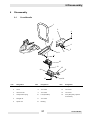
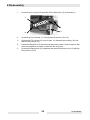
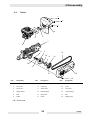
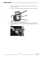
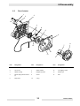
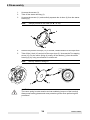
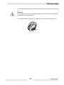
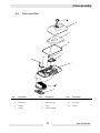
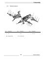
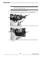
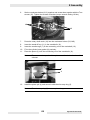
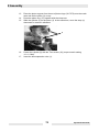
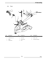
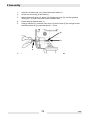
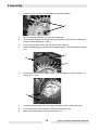
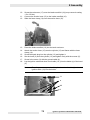
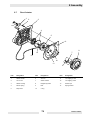
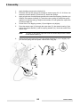
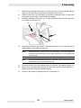
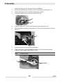
1
BTS 930L3
BTS 935L3
BTS 1030L3
BTS 1035L3
Repair Manual
Item number 0208118
Edition 03/06
Contents
1
Foreword . . . . . . . . . . . . . . . . . . . . . . . . . . . . . . . . . . . . . . . . . . . . . . . . . . . . . . . . . . 3
2
Safety instructions . . . . . . . . . . . . . . . . . . . . . . . . . . . . . . . . . . . . . . . . . . . . . . . . . . 5
2.1
Proper use . . . . . . . . . . . . . . . . . . . . . . . . . . . . . . . . . . . . . . . . . . . . . . . . . . . 5
2.2
General notes . . . . . . . . . . . . . . . . . . . . . . . . . . . . . . . . . . . . . . . . . . . . . . . . . 5
2.3
Fuel, Lubricants, and Coolants / Filling the tank . . . . . . . . . . . . . . . . . . . . . . . 6
2.4
Starting up. . . . . . . . . . . . . . . . . . . . . . . . . . . . . . . . . . . . . . . . . . . . . . . . . . . . 7
2.5
Cutting discs . . . . . . . . . . . . . . . . . . . . . . . . . . . . . . . . . . . . . . . . . . . . . . . . . . 8
2.6
Kickback and pulling motion . . . . . . . . . . . . . . . . . . . . . . . . . . . . . . . . . . . . . 11
2.7
Maintenance . . . . . . . . . . . . . . . . . . . . . . . . . . . . . . . . . . . . . . . . . . . . . . . . . 12
3
Starting up . . . . . . . . . . . . . . . . . . . . . . . . . . . . . . . . . . . . . . . . . . . . . . . . . . . . . . . . 13
3.1
Attaching the cutting disc . . . . . . . . . . . . . . . . . . . . . . . . . . . . . . . . . . . . . . . 14
3.2
Fuel, lubricants, and coolants . . . . . . . . . . . . . . . . . . . . . . . . . . . . . . . . . . . . 15
3.3
Storing fuel . . . . . . . . . . . . . . . . . . . . . . . . . . . . . . . . . . . . . . . . . . . . . . . . . . 17
3.4
Filling the tank. . . . . . . . . . . . . . . . . . . . . . . . . . . . . . . . . . . . . . . . . . . . . . . . 18
3.5
Starting the engine . . . . . . . . . . . . . . . . . . . . . . . . . . . . . . . . . . . . . . . . . . . . 19
3.6
Cold start. . . . . . . . . . . . . . . . . . . . . . . . . . . . . . . . . . . . . . . . . . . . . . . . . . . . 20
3.7
Warm start . . . . . . . . . . . . . . . . . . . . . . . . . . . . . . . . . . . . . . . . . . . . . . . . . . 21
3.8
Turning off the engine . . . . . . . . . . . . . . . . . . . . . . . . . . . . . . . . . . . . . . . . . . 21
3.9
Setting the carburetor . . . . . . . . . . . . . . . . . . . . . . . . . . . . . . . . . . . . . . . . . . 22
4
Technical data . . . . . . . . . . . . . . . . . . . . . . . . . . . . . . . . . . . . . . . . . . . . . . . . . . . . . 23
5
Special tools . . . . . . . . . . . . . . . . . . . . . . . . . . . . . . . . . . . . . . . . . . . . . . . . . . . . . . 25
6
Disassembly . . . . . . . . . . . . . . . . . . . . . . . . . . . . . . . . . . . . . . . . . . . . . . . . . . . . . . 27
6.1
Cover/Handle . . . . . . . . . . . . . . . . . . . . . . . . . . . . . . . . . . . . . . . . . . . . . . . . 27
6.2
Clutch . . . . . . . . . . . . . . . . . . . . . . . . . . . . . . . . . . . . . . . . . . . . . . . . . . . . . . 29
6.3
Recoil starter. . . . . . . . . . . . . . . . . . . . . . . . . . . . . . . . . . . . . . . . . . . . . . . . . 33
6.4
Filter cover/Filter . . . . . . . . . . . . . . . . . . . . . . . . . . . . . . . . . . . . . . . . . . . . . . 37
6.5
Ignition system module/intake manifold . . . . . . . . . . . . . . . . . . . . . . . . . . . . 39
6.6
Tank . . . . . . . . . . . . . . . . . . . . . . . . . . . . . . . . . . . . . . . . . . . . . . . . . . . . . . . 45
6.7
Cylinder/Crankshaft . . . . . . . . . . . . . . . . . . . . . . . . . . . . . . . . . . . . . . . . . . . 47
6.8
Vibration dampers. . . . . . . . . . . . . . . . . . . . . . . . . . . . . . . . . . . . . . . . . . . . . 51
6.9
Protective hood/V-belt pulley . . . . . . . . . . . . . . . . . . . . . . . . . . . . . . . . . . . . 53
7
Disassembly/Inspection . . . . . . . . . . . . . . . . . . . . . . . . . . . . . . . . . . . . . . . . . . . . . 57
7.1
Carburetor/Inspection . . . . . . . . . . . . . . . . . . . . . . . . . . . . . . . . . . . . . . . . . . 57
8
Assembly . . . . . . . . . . . . . . . . . . . . . . . . . . . . . . . . . . . . . . . . . . . . . . . . . . . . . . . . . 61
8.1
Protective hood/V-belt pulley . . . . . . . . . . . . . . . . . . . . . . . . . . . . . . . . . . . . 61
8.2
Vibration dampers. . . . . . . . . . . . . . . . . . . . . . . . . . . . . . . . . . . . . . . . . . . . . 65
8.3
Cylinder/Crankshaft . . . . . . . . . . . . . . . . . . . . . . . . . . . . . . . . . . . . . . . . . . . 67
8.4
Tank . . . . . . . . . . . . . . . . . . . . . . . . . . . . . . . . . . . . . . . . . . . . . . . . . . . . . . . 71
8.5
Ignition system module/intake manifold . . . . . . . . . . . . . . . . . . . . . . . . . . . . 73
0208118en_001IVZ.fm
1
Contents
8.6
8.7
8.8
8.9
Filter cover/Filter . . . . . . . . . . . . . . . . . . . . . . . . . . . . . . . . . . . . . . . . . . . . . .
Recoil starter. . . . . . . . . . . . . . . . . . . . . . . . . . . . . . . . . . . . . . . . . . . . . . . . .
Clutch . . . . . . . . . . . . . . . . . . . . . . . . . . . . . . . . . . . . . . . . . . . . . . . . . . . . . .
Cover/Handle . . . . . . . . . . . . . . . . . . . . . . . . . . . . . . . . . . . . . . . . . . . . . . . .
77
79
83
87
9
Malfunction . . . . . . . . . . . . . . . . . . . . . . . . . . . . . . . . . . . . . . . . . . . . . . . . . . . . . . . 89
10
Maintenance . . . . . . . . . . . . . . . . . . . . . . . . . . . . . . . . . . . . . . . . . . . . . . . . . . . . . . 91
10.1 Maintenance schedule . . . . . . . . . . . . . . . . . . . . . . . . . . . . . . . . . . . . . . . . . 91
10.2 Cleaning the protective hood . . . . . . . . . . . . . . . . . . . . . . . . . . . . . . . . . . . . 93
10.3 Replacing the V-belt . . . . . . . . . . . . . . . . . . . . . . . . . . . . . . . . . . . . . . . . . . . 94
10.4 Tightening the V-belt. . . . . . . . . . . . . . . . . . . . . . . . . . . . . . . . . . . . . . . . . . . 95
10.5 Carburetor setting . . . . . . . . . . . . . . . . . . . . . . . . . . . . . . . . . . . . . . . . . . . . . 96
10.6 Cleaning/Changing the air filter. . . . . . . . . . . . . . . . . . . . . . . . . . . . . . . . . . . 98
10.7 Replacing the spark plug . . . . . . . . . . . . . . . . . . . . . . . . . . . . . . . . . . . . . . 101
10.8 Replacing the suction head. . . . . . . . . . . . . . . . . . . . . . . . . . . . . . . . . . . . . 103
10.9 Replacing the starter rope. . . . . . . . . . . . . . . . . . . . . . . . . . . . . . . . . . . . . . 103
10.10 Miscellaneous . . . . . . . . . . . . . . . . . . . . . . . . . . . . . . . . . . . . . . . . . . . . . . . 104
11
Torque values . . . . . . . . . . . . . . . . . . . . . . . . . . . . . . . . . . . . . . . . . . . . . . . . . . . . 107
0208118en_001IVZ.fm
2
1 Foreword
1
Foreword
In the interest of your own safety and to prevent accidents, you should carefully
read through the safety instructions, familiarize yourself with them, and observe
them at all times.
The safety of the operator was one of the most important aspects taken into
consideration when this machine was designed. Nevertheless, improper use or
incorrect maintenance can pose a risk. Please operate and maintain your
Wacker machine in accordance with the instructions in the operator's manual.
Your reward will be troublefree operation and a high degree of availability.
Defective components should be replaced immediately!
If you have any questions regarding operation or maintenance, please contact
your Wacker representative.
All rights reserved, especially reproduction and distribution rights.
Copyright 2005 Wacker Construction Equipment AG
No part of this manual may be reproduced, processed, copied or distributed by
any means without the expressed written permission of Wacker.
Any type of reproduction, distribution or storage on data media of any type and
form not authorized by Wacker represents an infringement of copyright and will
be prosecuted.
We expressly reserve the right to make technical modifications - even without
special notice - which aim at further improving our machines or their safety
standards.
3
1 Foreword
4
2 Safety instructions
2
Safety instructions
2.1
Proper use
1.
Cut-off saw
•
2.
Non-approved work methods:
•
3.
The cutting discs of the cut-off saw must not be used as a grinding tool (removing material with the side surface of the cutting disc). This may cause the
disc to break! It is prohibited to attach saw blades, knives or brushes to the
cut-off saw.
Non-approved operators:
•
2.2
The cut-off saw must only be used outdoors for cutting/cutting to length suitable materials with the cutting disc approved for the unit.
Persons unfamiliar with the operator's manual, children, juveniles as well as
persons under the influence of alcohol, drugs or medication must not attempt
to operate the unit.
General notes
Note:
•
This repair manual is not intended to replace the operator's manual.
To ensure safe handling, the operating person must read the operator's
manual (even if that person is experienced in using a cut-off saw), to become familiar with the cut-off saw. Operators can endanger themselves and
others if they are unaware or insufficiently informed about how to properly
use the unit.
.
5
Proper use
2 Safety instructions
2.3
Fuel, Lubricants, and Coolants / Filling the tank
•
•
Before you fill the tank, go to a a safe and level area. It is prohibited to fill
the tank on a scaffolding, a mound of material or similar elevated structure!
Turn off the motor before you fill the tank of the cut-off saw.
1
•
•
•
•
•
•
•
Smoking and open fires are not permitted (1).
Let the motor cool down before you fill the tank.
Fuels can contain solvent-like substances. Avoid skin and eye contact with
mineral products. When filling the tank, wear gloves (not work gloves).
Change and wash your clothing more often. Do not inhale fuel vapors. Inhaling fuel vapors can damage your health.
Do not spill fuel. If you have spilled fuel, clean the cut-off saw immediately.
Avoid getting fuel on your clothing. Should you spill fuel on your clothing,
change your clothes immediately.
Make every effort to ensure that you do not allow fuel to soak into the ground
(environmental protection). Use a suitable base.
Do not fill the tank in closed rooms. Fuel vapors accumulate near the floor
(danger of explosion).
Tightly close the screw plug on the fuel tank.
3 meters
(10 feet)
2
•
•
•
•
•
To start the cut-off saw, go to another location (at least 3 meters (10 feet)
away from the place where you filled the tank) (2), however not in the extended swing area (direction of flying sparks) of the cutting disc.
Fuels cannot be stored indefinitely. Purchase only enough fuel as you can
possibly use in the foreseeable future.
When preparing the correct gasoline/oil mixing ratio, first always pour oil into
the mixing container and then the gasoline.
Transport and store fuel only in approved and specially marked canisters.
Do not allow children near the fuel.
6
Fuel, Lubricants, and Coolants / Filling the tank
2 Safety instructions
2.4
Starting up
•
•
•
Do not work alone; someone must be nearby in case of an emergency
(within calling distance).
When using cut-off saws in residential areas, please observe the local noise
regulations.
Do not use the cut-off saw near combustible materials or explosive gases. There is a risk of sparking.
= Wear protective gear
3
•
Ensure that persons (for example those assisting you) within a range of 30 m
(100 feet) also wear protective gear (see "Personal Protective Gear") (3).
Children or other persons must keep a distance of at least 30 m (100 feet)
from the work area of the cut-off saw. Be aware of any animals in the vicinity
(4).
4
•
•
•
Before you start to work with the cut-off saw, check to see that is in proper
working order and in a safe operating condition!
In particular, inspect the condition of the cutting disc (replace immediately if
the disc is cracked, bent or otherwise damaged). Check that the disc is properly mounted, the protective hood is locked in place, the belt guard is firmly
attached, the V-belt is properly tightened, the throttle lever moves unhindered
and functions correctly, the handles are clean and dry and the multifunction
switch works.
Do not start the cut-off saw until you have completely assembled and tested
it in operation. The cut-off saw must only be operated when it is completely
assembled!
7
Starting up
2 Safety instructions
2.5
Cutting discs
•
•
The protective hood must always be attached. Change the cutting disc only
when the motor has been turned off!
If you are using diamond-edged cutting discs, make sure you observe the attached rotational direction mark.
5
•
Cutting discs are only designed to cut materials on their edges. Never use the
side surfaces for grinding purposes as this can break the disc (5)!
6
Note:
•
•
min. 5 m
(16 feet)
It is prohibited to change the direction (a radius of 5 m (16 feet) or less),
apply lateral pressure or tilt the cut-off saw while you are cutting (6)!
Cutting discs must only be used to cut materials they were designed for. Depending on the material you wish to cut (metal or concrete), you must select
the proper disc type.
The center hole of the cutting disc must fit exactly onto the shaft. If the center
hole is larger, you must use an intermediate ring as an adapter.
8
Cutting discs
2 Safety instructions
•
The cutting disc must be approved for freehand cutting with a 350 mm (14")
cutting disc diameter up to 4370 rpm or 80 m/s (260 ft./sec) or with a 300 mm
(12") cutting disc diameter up to 5100 rpm or 80 m/s (260 ft./sec). Use only
cutting discs that comply with EN 12413, EN 13236 or with the BGV D 12.
7
•
•
•
The cutting disc must be completely undamaged (7). Test it by performing a
sound test with a piece of wood.
Always tighten the cutting disc to 30 Nm, otherwise you may distort the cutting disc.
Before starting, the operator must stand at safe distance away from the cutoff saw.
8
•
•
•
Start the cut-off saw only as described in the operator's manual (8) Always
set your left foot into the handle and firmly hold the bow handle grip handle
by using your thumb. Starting the unit in any other way is not permitted.
When you start up the machine, support it well and hold it firmly. The cutting
disc must be freestanding.
A new cutting disc must be tested before you cut with it by running it at least
60 seconds at the specified maximum speed. Ensure that no one is in the extended swing area of the cutting disc.
9
Cutting discs
2 Safety instructions
•
When operating the cut-off saw, hold it firmly with both hands. The right
hand on the rear handle, and the left hand on the bow handle grip. Hold the
grips firmly using your thumbs.
CAUTION
When you release the throttle lever, the cutting disc will continue to run briefly
(afterrun)
•
•
•
Always ensure that you are standing in a secure position.
Hold the cut-off saw in such a way that you cannot inhale the exhaust fumes.
Do not work in closed rooms or in deep trenches (danger of poisoning
through exhaust fumes).
If you notice any changes in the way the unit operates, turn off the motor immediately.
*Maintenance
*Filling the tank
*Changing the cutting disc
*Remounting the cutting
attachment
*Taking a break
*Transport
9
•
•
•
•
•
You must turn off the motor before you check the V-belt tension,
retighten the belt, change the cutting disc, remount the cutting attachment (outer or center position) and eliminate malfunctions (9).
If you hear or feel a change in the way the unit is cutting, turn off the motor
immediately and check the cutting disc.
During breaks and after you finish work, turn off the cut-off saw and set it
down so that the cutting disc is freestanding and cannot endanger anyone.
Do not lay the hot cutting disc on dry grass or onto combustible objects. The
muffler radiates an enormous amount of heat (danger of fire).
CAUTION: After a wet cutting procedure, first shut off the stream of water
and then let the cutting disc run another 30 seconds so that it can spin off the
remaining water. This prevents corrosion.
10
Cutting discs
2 Safety instructions
2.6
Kickback and pulling motion
•
When working with the cut-off saw, it can kick back or suddenly pull you.
Please see the relevant pages in the operator's manual.
11
Kickback and pulling motion
2 Safety instructions
2.7
Maintenance
10
•
•
•
•
•
•
Before you carry out any maintenance work, always turn off the cut-off
saw (10) and pull off the spark plug connector!
Check that the cut-off saw is in a safe operating condition before you start
work. Make sure that the cutting disc has been attached according to instructions. Alos make sure that the cutting disc is undamaged and suited for the
application at hand.
While operating the machine, try to produce as little noise and exhaust fumes
as possible. Check the carburetor setting.
Clean the cut-off saw regularly.
Check the tank cap regularly to make sure it is on tightly.
Observe the accident prevention regulations set forth by the professional liability insurance association. Never attempt to modify the cut-off saw! Doing
so will endanger your safety!
SERVICE
11
•
•
•
Maintenance and repair work must be carried out only to the extent detailed
in this repair manual. All other procedures must be performed by Wacker
Service.
Use only original Wacker replacement parts.
If you use non-original Wacker replacement parts, accessories and cutting
discs, you will increase you changes of having an accident. Any accidents or
damage that occur with non-original Wacker parts will invalidate your warranty.
12
Maintenance
3 Starting up
3
Starting up
CAUTION
Before working on the cut-off saw, always turn off the engine, pull off the spark
plug connector and wear protective gloves!
CAUTION
The cut-off saw must not be started until it has been completely assembled and
tested!
•
Always use the assembly tools included in delivery for the following procedures:
1. Combination wrench 13/19 mm
2. Offset screwdriver
3. Screwdriver for
setting the carburetor
1
•
2
3
Set the cut-off saw onto a sturdy base and carry out the following assembly
steps:
13
3 Starting up
3.1
Attaching the cutting disc
Diagram
Note:
•
Check the cutting disc for signs of damage. See the safety instructions
in the operator's manual.
Unscrew the screw (9) and remove the thrust washer (8). Set the cutting disc
(5) onto the shaft (7).
Note:
The center hole of the cutting disc must fit exactly onto the shaft. You
must use an adapter ring if the center hole is larger.
WARNING
If you are using diamond-edged cutting discs, make sure you observe the
attached rotational direction mark!
•
•
•
•
Set the thrust washer (8) onto the shaft, screw in together with the screw (9)
and tighten by hand.
Turn the cutting disc slowly until you can see the locking bore of the V-belt
pulley bolt through the gear arm hole (10).
Press the offset screwdriver (2) all the way in. The shaft is now blocked.
Firmly tighten the screw with the combination wrench (1).
Note:
Firmly tighten the screw to 30 + 2 Nm (22 + 1.5 ft.lbs.), otherwise the
cutting disc may slip while cutting.
14
Attaching the cutting disc
3 Starting up
3.2
Fuel, lubricants, and coolants
DANGER
The unit uses mineral oil products (gasoline and oil)!
Take special precautions when handling gasoline.
Smoking and open fires are not permitted (danger of explosion).
Fuel
50:1
+
1,000 cm3
(1 liter)
5,000 cm3
(5 liter)
10,000 cm3 (10 liters)
1.0 Us-gal.
2.5 Us-gal.
5.0 Us-gal.
20 cm3
100 cm3
200 cm3
2.5 floz.
6.4 floz.
12.8 floz.
Preparing the correct gasoline/oil
mixing ratio:
50:1 Mix 50 parts of fuel with one
part of oil.
Fuel mixture
•
•
The cut-off saw engine is a high-performance two-cycle engine. It is operated
with a mixture of fuel and two-cycle motor oil.
The engine is designed for use with normal leadfree gasoline with a minimum
octane rating of 91 ROZ. If this octane is not available, you may also use fuel
of a higher octane rating. This will not damage your engine.
15
Fuel, lubricants, and coolants
3 Starting up
•
•
For optimum engine performance and for the sake of your own health and the
environment, always use leadfree fuel!
The two-cycle motor oil must meet the specification API TC, JASO FC or ISO
L-EGD.
Note:
To prepare the fuel-oil mixture, always premix the prescribed amount
of oil volume with half of the fuel volume and then add the remaining
amount of fuel. Before you fill the tank, always shake the finished mixture well.
CAUTION
Open the cap of the fuel tank carefully since there may be pressure present!
•
It is not a good idea to increase the oil percentage of the two-cycle mixture
for beyond the specified mixing ratio for any reason. This will increase the
amount of combustion residue which pollutes the environment and also clogs
the exhaust port in the cylinder and the muffler. Furthermore, this also increases fuel consumption and reduces engine performance.
16
Fuel, lubricants, and coolants
3 Starting up
3.3
Storing fuel
•
•
Fuels cannot be stored indefinitely. Purchase only enough fuel as you can
possibly use in 4 weeks.
Store fuel only in approved and specially marked containers.
AVOID CONTACT WITH SKIN AND EYES!
•
•
Mineral products and oils scour your skin. If used repeatedly and over time,
they will dry out your skin. This could develop into one of various skin diseases. In addition, allergic reactions are also possible.
Oil in your eyes can cause irritations. If you get oil into your eye, rinse it out
immediately with clean water.
If irritation continues, consult a physician immediately!
17
Storing fuel
3 Starting up
3.4
Filling the tank
Fuel mixture
Note:
•
•
•
•
•
•
•
Strictly observe the safety instructions in the operator's manual!
Fuels must be handled carefully and prudently.
Only when the engine is turned off and has cooled down!
Clean the filling area so that no dirt can get into the tank.
Set the machine on its side on a flat base.
Screw off the tank cap and pour in the fuel mixture. Pour it in carefully to avoid
spilling the fuel mixture.
Tightly screw the tank cap back on.
Clean the tank cap and surrounding area after you are finished! Never start
or operate the unit at the location where you filled the tank! Should you spill
fuel on your clothing, change your clothes immediately.
18
Filling the tank
3 Starting up
3.5
Starting the engine
if
required
Note:
•
•
•
•
•
Strictly observe the safety instructions in the operator's manual.
The cut-off saw must not be started until it has been completely assembled
and tested!
Take it at least 3 m (10 feet) away from the place where you filled the tank!
Stand squarely and set the cut-off saw onto the ground so that the cutting attachment is freestanding.
Move the protective hood (3) to the best position for the application at hand
(see figure).
Grab the handle (2). The protective hood (3) can be swivelled within the stopmounts in both arrow directions.
CAUTION
Make absolutely sure that the straight edge of the stop plate (4) is parallel to the
edge of the protective hood (see arrows).
If this is not the case, please take your unit to the shop.
19
Starting the engine
3 Starting up
3.6
Cold start
•
•
•
•
•
•
•
•
Press the multifunction switch (5) upward (choke position).
Put your hand around the handle (safety switch (7) is actuated by the palm of
your hand)
Press the throttle lever (8) all the way through and hold it.
Press the lock button (6) and release the throttle lever (8) (throttle lever is
locked in place by the lock button in the half-gas position). Press in the start
valve (4).
Put your hand around the bow handle grip and hold it firmly while you press
the cut-off saw against the ground.
Place your left foot into the rear hand guard.
Pull out the starter rope slowly until you feel resistance (the piston is located
before the top dead center).
Now continue pulling quickly with force until you hear the engine start.
CAUTION
Do not pull out the starter rope more than 50 cm (20") and let it rewind slowly by
hand, not letting it go.
•
•
•
Press the multifunction switch (5) to the "I" position.
Pull the starter rope again until the engine runs.
Once the engine is running, tip the throttle lever (8) so that the lock button (6)
snaps out and the engine idles.
20
Cold start
3 Starting up
3.7
Warm start
•
3.8
As described under cold start, however without pressing the multifunction
switch (5) in the choke position.
Turning off the engine
•
Press the multifunction switch (9) down to the "Stop" position.
21
Warm start
3 Starting up
3.9
Setting the carburetor
Set the idle speed with a flathead
screwdriver (head width 4 mm/0.16").
The screwdriver shown has a moulded
nose that can be used as a setting tool.
Note:
The cut-off saws are equipped with a speed limiting electronic ignition.
In addition, the carburetor has a fixed nozzle that cannot be adjusted.
•
The idle speed has been factory set to approx. 2500 rpm; however, the runin procedure of a new machine requires a slight readjustment of the idle
speed.
•
•
The following steps are required to correctly set the idle speed:
Start the engine and let it warm up (approx. 3 - 5 minutes).
•
Make the carburetor setting with the screwdriver that was included in delivery.
Readjust the idle speed
If the cutting disc rotates when the engine is running, screw the stop screw
"S" (2) for the choke outward until the cutting disc no longer rotates. If the emgine stops when idling, turn the screw back in somewhat.
•
•
Turn off the engine
22
Setting the carburetor
4 Technical data
4
Technical data
Unit
Item no.
BTS
930L3
BTS
935L3
BTS
1030L3
BTS
1035L3
0008987...
0610073...
0008988...
0610074...
0008989...
0610075...
0008990...
0610076
Engine displacement
m³
64
73
Bore
mm
47
50
Stroke
mm
Max. performance
kW
3.3
4.2
Max. torque
Nm
4.0
5.0
Idle speed
rpm
2,500
Clutch engaging speed
rpm
3,800
Limiting speed
rpm
9,350
Nominal spindle speed
rpm
4,300
Sound pressure level LpA eq
according to EN 1454 1) 4)
dB(A)
97
99
Sound power level
LWA
109 dB(A)
110 dB(A)
Vibrational acceleration ah,w
according to EN 1454
- Bow handle grip (idle/nominal
spindle speed)
- Handle (idle/nominal spindle
speed)
m/s2
6/5
7/5
8/6
8/7
Carburetor (diaphragm
carburetor)
37
TILLOTSON HS-273 A
Ignition system (with maximum
rpm limitation)
Electronic
Spark plug
NGK BPMR 7A / BOSCH WSR 6F / CHAMPION RCJ 6Y
Spark plug air gap
mm
Fuel consumption at max.
capacity according to ISO 8893
l/h
Special consumption at max.
capacity according to ISO 8893
g/kWh
500
Fuel tank capacity
l
1.1
23
0.5
2.1
2.7
4 Technical data
BTS
930L3
Unit
BTS
935L3
Gasoline/2-cycle oil mixing ratio
5)
BTS
1030L3
BTS
1035L3
50:1
Cutting disc for max. 80 m/s 2)
mm
300/20.0/
53)
350/25.4/
53)
300/20.0/
53)
350/25.4/
53)
Spindle diameter
mm
20.0
25.4
20.0
25.4
Weight of cut-off saw (empty
tank, without cutting disc)
kg
10.0
10.2
10.0
10.2
1) Data takes the operating states idle and top speed equally into consideration.
2) Peripheral speed at the highest engine speed.
3) Outer diameter/centre bore/thickness.
4) At the working area (operator's ear).
5) With 2-cycle motor oil of the specification API TC, JASO FC. or ISO L-EGD
24
5 Special tools
5
Special tools
0068900
0079264
0117574
0117571
0117575
0128935
0128936
0128937
Item no.
Designation
Item no.
Designation
0068900
Magnet wheel puller
0117575
Piston ring band clamps
0079264
Pressure gauge tester
0128935
Insert for screws TX27 (152 long)
0117571
Piston stop wedge
0128936
Insert for screws TX27 (49 long)
0117574
Installation wrench
0128937
Connecting piece (3/8" square input
socket)
25
5 Special tools
26
6 Disassembly
6
Disassembly
6.1
Cover/Handle
1
2
3
7
4
5
6
8
9
10
11
12
16
13
15
Item
Designation
Item
Designation
14
Item
Designation
1
Handle
7
Side brace
13
Pulley
2
Cover
8
Torx screw
14
Torx screw
3
Tension screw
9
Torx screw
15
Torx screw
4
Compression spring
10
Foot (standard)
16
Foot (with pulley, optional
accessories)
5
Flanged nut
11
Torx screw
6
Square nut
12
Bushing
27
Cover/Handle
6 Disassembly
1.
Unscrew the 3 screws (8,9) and take off the side brace (7) and handle (1).
7
8
1
9
2.
Unscrew the Torx screws (11,15) and take off the foot (10 or 16).
3.
Unscrew the Torx screw (14) only for item 16, dismantle the bushing (12) and
take out the pulleys (13).
4.
Loosen the flanged nut (5) and unscrew the tension screw (3) far enough so that
the screw end does not make contact with the enclosure.
5.
Unscrew the flanged nut (5) completely and take off the entire cover (2) with the
fixing device (3,4,6).
28
Cover/Handle
6 Disassembly
6.2
Clutch
1
2
3
4
5
6
7
x
9
8
13
10
11
12
18
17
16
14
15
Item
Designation
Item
Designation
Item
Designation
1
Exhaust
7
Crankcase half (CS)
13
V-belt
2
Torx screw
8
Snap ring
14
Cover
3
Torx screw
9
Clutch drum
15
Torx screw
4
Spring washer
10
Needle sleeve
16
Tension spring
5
Seal
11
Guide disc
17
Disc
6
Guard
12
Clutch
18
Stopping ring
CS = Clutch side
29
Clutch
6 Disassembly
1.
Unscrew the Torx screws (15) out of the cover (14) and take off the cover (14).
2.
Take off the V-belt (13).
3.
Unscrew the Torx screws (2,3) with the spring washers (4) from the exhaust (1).
2
1
3,4
4.
Take off the exhaust (1), seal (5) with guard (6).
5.
To disassemble the clutch (12) and clutch drum (9), you must block the piston.
To do this, slide the piston stop wedge (0117571) into the exhaust port of the cylinder (x).
x
0117571
30
Clutch
6 Disassembly
6.
Loosen the clutch (12) with installation wrench (0117574) and a 19 mm ring
wrench (x).
Note:
Left-hand thread!
x
0117574
7.
You can remove the tension springs (16) of the clutch (12) by using needle-nose
pliers (x).
16
x
8.
Take out the guide disc (11).
9.
Press out the needle sleeve (10).
10.
Remove the snap ring (8), take out the disc (17) and stopping ring (18).
31
Clutch
6 Disassembly
32
Clutch
6 Disassembly
6.3
Recoil starter
1
3
2
14
4
z
5
6
8
7
12
13
10
11
9
Item
Designation
Item
Designation
Item
Designation
1
Starter handle
6
Air horn
11
Torx tapping screw
2
Torx screw
7
Starter ratchet
12
Torx tapping screw
3
Starter housing
8
Magneto flywheel
13
Starter rope
4
Return spring with enclosure
(z)
9
Screw
14
Disc
5
Rope drum
10
V-ring
33
Recoil starter
6 Disassembly
1.
Unscrew the screws (2).
2.
Take off the starter housing (3).
3.
Unscrew the screws (11) and carefully separate the air horn (6) from the starter
housing (3).
Note:
Always proceed in the order (A - B - C - D).
B
6
A
D
C
4.
Remove any leftover old rope (13). If needed, release tension on the rope drum.
5.
Take off the V-belt (10) and pull off the rope drum (5). Unscrew the Torx tapping
screw (12). Pry the return spring (4) evenly off the latches (y) from the starter
housing (3) by using a screwdriver or similar tool.
Note:
Be very careful in doing so.
y
y
z
y
y
CAUTION
The return spring is under tension and can suddenly jump out of the housing!
Always wear safety glasses and wear protective gloves when performing this
procedure!
34
Recoil starter
6 Disassembly
6.
The replacement return spring is delivered already under tension in the housing
(z).
CAUTION
The spring can jump out. A released spring can be reinserted; see Chapter 8.7
"Assembling the recoil starter."
7.
To change the starter ratchets (7), knock out the bolt (9) with a mandrel (x).
x
35
Recoil starter
6 Disassembly
36
Recoil starter
6 Disassembly
6.4
Filter cover/Filter
1
2
3
4
5
6
11
10
7
8
9
Item
Designation
Item
Designation
Item
1
Bayonet cap
5
Lower part of the plug
2
Filter cover
6
Spark plug cap
10
Torx screw
3
Prefilter
7
Hood
11
Gasket
4
Gasket
8
Air filter cartridge
37
9
Designation
Internal filter
Filter cover/Filter
6 Disassembly
1.
Open the bayonet cap (1) and take off the filter cover (2) with the prefilter (3).
2.
Remove the seal rings (4,11).
4
11
3.
Detach the spark plug terminal cap (6).
6
4.
Remove the lower part of the plug (5).
5.
Unscrew the Torx screws (10) and take off the hood (7).
6.
Take off the air filter cartridge (8).
7.
Remove the internal filter (9) from the intake manifold (x).
x
9
38
Filter cover/Filter
6 Disassembly
6.5
Ignition system module/intake manifold
1
2
18
3
5
9
6
21
7
8
10
20
4
11
12
13
19
x 16
18
Item
Designation
1
Short circuit cable
2
15
14
17
Item
Designation
Item
Designation
9
Contact spring
17
Carburetor
Hood
10
Ignition cable
18
Choke shaft
3
Screw
11
Torx screw
19
Magneto flywheel
4
Ground cable
12
Magneto igniter
20
Spring washer
5
Screw
13
Cylinder
21
Hexagonal nut
6
Spark plug terminal cap
14
Hose clamp
7
Spark plug
15
Suction hose
8
Spring
16
Intake manifold
39
Ignition system module/intake manifold
6 Disassembly
1.
Take the ignition cable and short circuit cable (10,1) out of the guides (x) of the
hood (2).
2
x
10
1
2.
Pull off the spark plug terminal cap (6) from the spark plug (7).
3.
Hold the spring (8) of the spark-plug connector (6) with needle-nose pliers and
slide the rubber cap to the rear over the ignition cable (10).
8
Note:
4.
Apply a small amount of grease to the ignition cable (10) to make it
easier to detach and attach the spark plug connector (6).
Remove the spark plug (7) with the combination wrench included in delivery.
40
Ignition system module/intake manifold
6 Disassembly
5.
Unscrew the screws (3,5) and remove the hood (2).
6.
The screw (5) also functions as the fastener for the ground cable.
7.
Unscrew the Torx screws (11) from the magneto igniter (12), disconnect the ignition cable (10).
8.
Release the short circuit cable (1) from the plug connection.
9.
Release the hose clamp (14) from the suction hose.
10
11
14
10.
Pull off the suction hose (15) from the cylinder (13).
15
41
Ignition system module/intake manifold
6 Disassembly
11.
Lift the intake manifold (16) from the tank enclosure by pressing the lever (x).
x
x
12.
Lift the intake manifold (16) with carburetor (17) and choke shaft (18) on the cylinder side and take it out of the tank enclosure.
42
Ignition system module/intake manifold
6 Disassembly
13.
Pull the short circuit cable (1) out of the seat in the choke shaft (18).
14.
Release the ground cable (4) from the plug connection of the contact spring (9).
4
9
1
18
15.
Block the piston with the piston stop wedge (0117571).
16.
Unscrew the nut (21) and take off the disc (20).
17.
Pull off the magneto flywheel (19) with the puller (0068900).
CAUTION
To prevent damage to the crankshaft, always use the protection cap that
belongs to the puller.
43
Ignition system module/intake manifold
6 Disassembly
44
Ignition system module/intake manifold
6 Disassembly
6.6
Tank
9
11
8
1
2
3
10
4
6
7
5
Item
Designation
Item
Designation
Item
1
Parallel pin
5
Handle shell
2
Throttle lever lock
6
Vent valve
10
Suction hose
3
Spring
7
Suction head
11
Gasoline locking pin
4
Throttle lever
8
Seal
45
9
Designation
Fuel cap
Tank
6 Disassembly
1.
Only if it becomes necessary, press in the vent valve (6) into the tank (x) with a
mandrel and take it out through the filler opening with needle-nose pliers.
6
x
2.
Press the two cylinder bolts (1) out of the handle shell (5).
3.
The throttle lever (4), spring (3), throttle lever lock (2), and the gasoline locking
pin (11) can now be replaced.
4.
Pull the suction hose (10) out of the tank and remove the suction head (7).
5.
Screw off the fuel cap (9) with seal (8).
46
Tank
6 Disassembly
6.7
Cylinder/Crankshaft
1
2
16
15
14
3
4
5
6
9
7
8
13
12
8
11
10
Item
Designation
Item
Designation
Item
Designation
1
Decompression valve
7
Needle cage
13
Crankcase half (MS)
2
Cylinder
8
Ball bearing
14
Rotary shaft seal
3
Piston
9
Crankcase half (CS)
15
Torx screw
4
Piston pin
10
Crankshaft
16
Torx screw
5
Wire snap ring
11
Woodruff key
6
Cylinder base gasket
12
Crankcase gasket
CS = Clutch side
MS = Magnet side
47
Cylinder/Crankshaft
6 Disassembly
1.
Unscrew the screws (16) from the cylinder (2).
2.
Pull the cylinder (2) with cylinder base gasket (6) off of the crankcase halves
(9,13) and piston (3).
16
3.
Take out the wire snap ring (5) from the ring groove in the piston (3) using needle-nose pliers (x).
4.
Press out the piston pin (4) and take off the piston.
5
x
5.
Press the needle cage (7) out of the connecting rod of the crankshaft (10).
48
Cylinder/Crankshaft
6 Disassembly
6.
Unscrew the decompression valve (1) and check the valve seat as well as the
bore in the cylinder (2) for dirt.
7.
Replace the dirty decompression valve (1). Carefully clean the bore.
1
8.
Remove the woodruff key (11).
9.
Unscrew the 4 screws (15) from the crankcase half (13).
Note:
10.
A slip fit is located between the crankshaft (10) and the ball bearing (8)
on the magnet side (MS). For this reason, always remove the "MS"
first.
Carefully separate the two crankcase halves (9,13) by using a plastic mallet (x).
x
11.
Remove the rotary shaft seal (14).
12.
To remove the ball bearings (8), always heat the crankcase halves (9,13) to approx. 100 to 120 °C (industrial dryer).
13.
Pull off the ball bearings (8) from the crankshaft (10).
49
Cylinder/Crankshaft
6 Disassembly
50
Cylinder/Crankshaft
6 Disassembly
6.8
Vibration dampers
1
2
3
4
5
3
4
6
MS
CS
3
Item
Designation
Item
Designation
4
3
2
1
Item
Designation
1
Torx screw
3
Vibration dampers
5
Holder cup
2
Disc
4
Shaft
6
Torx screw
MS = Magnet side
CS = Clutch side
51
Vibration dampers
6 Disassembly
1.
Unscrew the Torx screw (1) from the crankcase half (MS) and remove the disc
(2).
2.
Press the axle (4) out of the vibration dampers (3).
3.
Pry out the vibration dampers (3) using a screwdriver.
3,4
2
1
4
3
4.
Remove the 2 vibration dampers (3) from the crankcase half (CS) the same way
as for the crankcase half (MS).
5.
Remove the Torx screw (6) and cup attachment (5) from the crankcase half (CS).
6.
Press out the axle (4) and pry out the vibration dampers (3) by using a screwdriver.
5
6
4
3
3
52
Vibration dampers
6 Disassembly
6.9
Protective hood/V-belt pulley
1
3
4
5
8
6
7
9
10
2
6
13
14
13
4
11
14
12 21
20
18
19
17
16
15
Item
Designation
Item
Designation
Item
Designation
1
Hexagonal bolt
8
Protective hood
15
V-belt pulley
2
Thrust washer
9
Handle
16
Shim ring
3
Shaft
10
Torx screw
17
Screw
4
Distance bushing
11
Outer rubber ring
18
Spring
5
Thrust collar
12
Stop flange
19
Cutting attachment
6
Sliding washer
13
Retaining clip
20
Screw
7
Inner rubber ring
14
Ball bearing
21
Stop pin
53
1
Protective hood/V-belt pulley
6 Disassembly
1.
Unscrew the screw (1) and remove the thrust washer (2).
2
1
2.
Block the V-belt pulley (15) by inserting a mandrel into the bore (x).
3.
Unscrew the hexagonal bolt (1) and take off the V-belt pulley (15) with shim ring
(16).
15
1
x
4.
To remove the second thrust washer (2), you must remove the axle (3) and distance bushing (4).
54
Protective hood/V-belt pulley
6 Disassembly
5.
Unscrew the screws (17) with springs (18) from the thrust collar (5).
6.
Take off the entire protective hood (8) with the parts 5,6,7,11,12.
7.
Unscrew the Torx screws (10) and take off the handle (9).
17,18
8.
Press the stop pin (21) and the screws (20) out of the cutting attachment (19).
21
20
19
9.
Heat the cutting attachment (19).
10.
Press out the ball bearing (14) and distance bushing (4).
11.
Remove the retaining clip (13), disassemble the ball bearing (14) and the second
retaining clip (13).
19
14
13
4
55
13
Protective hood/V-belt pulley
6 Disassembly
56
Protective hood/V-belt pulley
7 Disassembly/Inspection
7
Disassembly/Inspection
7.1
Carburetor/Inspection
1
2
3
4
5
6
11
7
8
9
10
Item
Designation
Item
Designation
1
Screw
5
Carburetor fuel screen
2
Cover
6
3
Seal
4
Pump diaphragm
Item
Designation
9
Cover
Needle valve set
10
Screw
7
Seal
11
Screw
8
Control diaphragm
57
Carburetor/Inspection
7 Disassembly/Inspection
1.
To disassemble the control side, unscrew the screws (10), carefully take off the
cover (9), control diaphragm (8), seal (7) from the needle valve set (6).
2.
After the control diaphragm (8) has been removed, it must lie flat. The rounded
edge on the reinforcement plate (x) must be flat. Always replace the control diaphragm (8) if it is defective.
7
x
8
3.
Unscrew the screw (11) and take off the needle valve set (6).
4.
If there are signs of wear on the fuel inlet needle (see arrows), always replace
the needle valve set (6).
11
5.
To disassemble the pump side, unscrew the screws (1), take off the cover (2),
seal (3), and pump diaphragm (4).
6.
The two valve flaps (x) must lie flat on the carburetor body.
7.
Replace damaged pump diaphragm (4), as this can cause starting and operation
problems.
x
x
58
Carburetor/Inspection
Carburetor Inspections
7 Disassembly/Inspection
8.
For cleaning purposes, you can take out the carburetor fuel screen (5) out of the
carburetor body by carefully using a pointed object.
9.
After you clean the carburetor fuel screen (5), insert it with a pin.
5
10.
To test the carburetor while installed, take the fuel line out of the tank. Pull off the
suction head. Set the pressure gauge (0079264) onto the reducing socket.
11.
Apply 0.5 bar of pressure to the carburetor. Excessively high pressures can damage the diaphragms. The pressure should remain constant.
59
Carburetor/Inspection
7 Disassembly/Inspection
60
Carburetor/Inspection
8 Assembly
8
Assembly
8.1
Protective hood/V-belt pulley
1
3
4
5
8
6
7
9
10
2
6
13
14
13
4
11
14
12 21
20
18
19
17
16
15
Item
Designation
Item
Designation
Item
Designation
1
Hexagonal bolt
8
Protective hood
15
V-belt pulley
2
Thrust washer
9
Handle
16
Shim ring
3
Shaft
10
Torx screw
17
Screw
4
Distance bushing
11
Outer rubber ring
18
Spring
5
Thrust collar
12
Stop flange
19
Cutting attachment
6
Sliding washer
13
Retaining clip
20
Screw
7
Inner rubber ring
14
Ball bearing
21
Stop pin
61
1
Protective hood/V-belt pulley
8 Assembly
1.
Attach the outer retaining clip (13).
2.
Heat the cutting attachment (19) to approx. 100 °C (use industrial hot air gun).
3.
Press the ball bearing (14) up against the retaining clip (13).
4.
Insert the second retaining clip (13) and spacer bushing (4).
5.
Also press the second ball bearing (14) up against the retaining clip (13).
19
13
14
13
4
6.
Apply bonding compound to the fluted area (x) on the screws (20).
7.
Insert the screws (20) and stop pin (21).
8.
Mount the complete hood (8) with the parts 6,12,11,7,6 and 5 and screw the
screws (17) with springs (18) into the thrust collar (5) (torque wrench setting
10 Nm).
Note:
When attaching the hood, make sure you follow the correct order of the
parts (see Fig. 8.1).
1
8
2
3
2
5
6
7
62
4
Protective hood/V-belt pulley
8 Assembly
9.
Set the inner thrust washer (2) and the distance bushing (4) onto the axle (3).
10.
Insert the axle (3) into the cutting attachment (19) that is premounted to the hood.
11.
Attach the shim ring (16) onto the axle (3).
12.
Hold the V-belt pulley (15) against it, block it by inserting a mandrel through the
bore (x) and screw it on with the hexagonal bolt (1) (torque wrench setting
25 + 5.0 Nm).
13.
Screw on the handle (9) with the Torx screw (10).
9
10
15
1
x
Note:
The V-belt pulley (15) is not fastened until the cutting disc is attached.
63
Protective hood/V-belt pulley
8 Assembly
64
Protective hood/V-belt pulley
8 Assembly
8.2
Vibration dampers
1
2
3
4
5
3
4
6
MS
CS
3
Item
Designation
Item
Designation
4
3
2
1
Item
Designation
1
Torx screw
3
Vibration damper
5
Holder cup
2
Disc
4
Shaft
6
Torx screw
MS = Magnet side
CS = Clutch side
65
Vibration dampers
8 Assembly
Note:
Apply grease to the vibration dampers (3) before you install them.
MS crankcase:
1.
Press the axle (4) with the collar inward into the vibration damper (3).
2.
Fasten with disc (2) and Torx screw (1).
3,4
2
1
CS crankcase:
3.
Insert the vibration damper (3) into the crankcase at the rear.
4.
Press the axle (4) with the collar inward into the vibration damper (3) and fasten
it with the disc (2) and Torx screw (1) to the enclosure (torque wrench setting
6 ± 0.5 Nm).
5.
Press the axle (4) into the vibration damper (3) and set it into the holder cup (5)
with the Torx screw (6).
6.
Screw the holder cup (5) onto the crankcase (torque wrench setting 6 ± 0.5 Nm).
5
6
4
3
3
66
Vibration dampers
8 Assembly
8.3
Cylinder/Crankshaft
1
2
16
15
14
17
3
4
5
6
9
7
x
8
13
12
8
11
10
Item
Designation
Item
Designation
Item
Designation
1
Decompression valve
7
Needle cage
13
Crankcase half (MS)
2
Cylinder
8
Ball bearing
14
Rotary shaft seal
3
Piston
9
Crankcase half (CS)
15
Torx screw
4
Piston pin
10
Crankshaft
16
Torx screw
5
Wire snap ring
11
Woodruff key
17
Piston ring
6
Cylinder base gasket
12
Crankcase gasket
CS = Clutch side
MS = Magnet side
67
Cylinder/Crankshaft
8 Assembly
Note:
The exposed side of the ball bearing (8) faces the crankshaft. Apply
Omnifit 100M to the ball bearings on the outer ring before you insert
them in the crankcase (CS, MS).
1.
Press the ball bearing (8) onto the crankshaft (10).
2.
Heat the crankcase half (9) to approx. 100 - 120 °C (use industrial hot air gun).
3.
Insert the crankshaft (10) with ball bearing (8) in the crankcase half (9).
9
a
8
4.
Heat the crankcase half (13) to approx. 100 - 120 °C (use industrial hot air gun)
and press in the ball bearing (8).
13
a
8
5.
Place the crankcase gasket (12) on top, center the seal over the clamping sleeve
(x - page 67).
68
Cylinder/Crankshaft
8 Assembly
6.
Set the crankcase halves (9,13) together and screw them together with the Torx
screws (15). Tighten the screws crosswise (torque wrench setting 10 Nm).
.
15
15
7.
Press the rotary shaft seals (14) into the crankcase halves (CS, MS).
8.
Insert the woodruff key (11) in the crankshaft (10).
9.
Insert the needle cage (7) in the connecting rod of the crankshaft (10).
10.
Fit in the cylinder base gasket (6) precisely.
11.
Place the piston (3) onto the connecting rod of the crankshaft (10).
Note:
The arrow on the top side of the piston must face in the direction of the
exhaust.
6
3
12.
Install the piston pin (4) and secure it with the wire snap ring (5).
Note:
The wire snap ring (5) must snap into the groove.
69
Cylinder/Crankshaft
8 Assembly
13.
Place the piston support from the set of piston rings (0117575) onto the crankcase and set the piston (3) on top.
14.
Press the piston ring (17) together with the clamp set.
15.
Slide the cylinder (2) on the piston (3). At the same time, move the strap (x)
downward or remove it afterward.
x
16.
Fasten the cylinder (2) with the Torx screws (16) (torque wrench setting
14 + 1.0 Nm).
17.
Insert the decompression valve (1).
70
Cylinder/Crankshaft
8 Assembly
8.4
Tank
9
11
8
1
2
3
10
4
6
7
5
Item
Designation
Item
Designation
Item
1
Parallel pin
5
Tank
2
Throttle lever lock
6
Vent valve
10
Suction hose
3
Spring
7
Suction head
11
Gasoline locking pin
4
Throttle lever
8
Seal
71
9
Designation
Fuel cap
Tank
8 Assembly
1.
Insert the suction hose (10), attach the suction head (7).
2.
Screw in the fuel cap (9) and seal (8).
3.
Mount the throttle lever (4), spring (3), throttle lever lock (2), and the gasoline
locking pin (11) and insert them into the handle shell.
4.
Fasten with the parallel pins (1).
5.
Using a mandrel (x), press the vent valve (6) into the tank (5) far enough so that
the white plastic tip (y) protrudes about 2 - 3 mm.
6.
Screw the tank (5) together with the premounted crankcase.
72
Tank
8 Assembly
8.5
Ignition system module/intake manifold
1
2
18
3
5
9
6
21
7
8
10
20
4
11
12
13
19
16
18
Item
Designation
1
Short circuit cable
2
15
14
17
Item
Designation
Item
Designation
9
Contact spring
17
Carburetor
Hood
10
Ignition cable
18
Choke shaft
3
Screw
11
Torx screw
19
Magneto flywheel
4
Ground cable
12
Magneto igniter
20
Spring washer
5
Screw
13
Cylinder
21
Hexagonal nut
6
Spark plug terminal cap
14
Hose clamp
7
Spark plug
15
Suction hose
8
Spring
16
Intake manifold
73
Ignition system module/intake manifold
8 Assembly
1.
Clean the cone (x) of the crankshaft and magneto flywheel.
x
2.
Set the magneto flywheel (19) onto the crankshaft.
3.
Screw the hexagonal nut (21) with the spring washer (20) onto the crankshaft
(torque wrench setting 30 - 5 Nm).
4.
Connect the ignition cable (10) and short circuit cable (1).
5.
Set the setting gauge (y) between the magneto igniter (12) and magneto flywheel
(19).
y
12
19
6.
Press firmly against the magneto igniter (12) and tighten the Torx screws (11)
evenly to 6 + 1 Nm.
11
7.
Insert the ground cable (4) in the plug connection of the contact spring (9).
8.
Connect the short circuit cable (1) with the choke shaft (18).
9.
Mount the choke shaft (18) to the carburetor (17).
74
Ignition system module/intake manifold
8 Assembly
10.
Screw the carburetor (17) onto the intake manifold (16) (torque wrench setting
1.5 ± 0.5 Nm).
11.
Connect the suction hose (15) to the intake manifold (16).
12.
Slide the hose clamp (14) over the suction hose (15).
13.
Place the intake manifold (16) into the tank enclosure.
14.
Attach the suction hose (15) onto the cylinder (13) and fasten with the hose
clamp (14).
15.
Screw the spark plug into the cylinder (13) and tighten it.
16.
Set the hood (2) onto the cylinder (13) and tighten firmly with the screws (5).
17.
Screw in the screw (3) with the ground cable (4).
18.
Lay the ignition cable and short circuit cable (10,1) into the holder (z) of the hood
(2).
Note:
For safety reasons, you should lay the short circuit cable (1) under the
ignition cable (10) into the holder.
2
z
10
1
75
Ignition system module/intake manifold
8 Assembly
19.
Press in the hook (w) of the spring (8) into the center of the ignition cable (10)
from the top.
20.
Pull the rubber cap over the spring (8).
w
8
Note:
21.
An incorrectly mounted spring (8) can cause weak ignition sparks or
lead to complete failure.
Plug the spark plug terminal caps (6) onto the spark plugs (7).
76
Ignition system module/intake manifold
8 Assembly
8.6
Filter cover/Filter
1
2
3
4
5
6
11
10
7
8
9
Item
Designation
Item
Designation
Item
1
Bayonet cap
5
Lower part of the plug
2
Filter cover
6
Spark plug cap
10
Torx screw
3
Prefilter
7
Hood
11
Gasket
4
Gasket
8
Air filter cartridge
77
9
Designation
Internal filter
Filter cover/Filter
8 Assembly
1.
Lay the internal filter (9) into the intake manifold (x).
x
9
2.
Set the air filter cartridge (8) onto the internal filter (9).
3.
Screw the hood (7) onto the intake manifold (x) with the Torx screws (10).
4.
Insert the seal rings (4,11).
4
11
5.
Insert the lower part of the plug (5).
6.
Attach the spark plug cap (6).
6
7.
Press the prefilter (3) into the filter cover (2).
Note:
8.
Align the prefilter (3) with the filter cover holder.
Set the filter cover (2) on top and lock with the bayonet cap (1).
78
Filter cover/Filter
8 Assembly
8.7
Recoil starter
1
3
2
14
4
5
6
8
7
12
13
10
11
9
Item
Designation
Item
Designation
Item
Designation
1
Starter handle
6
Air horn
11
Torx tapping screw
2
Torx screw
7
Starter ratchet
12
Torx tapping screw
3
Starter housing
8
Magneto flywheel
13
Starter rope
4
Return spring
9
Bolt
14
Spring washer
5
Rope drum
10
V-ring
79
Recoil starter
8 Assembly
1.
Apply bonding compound to the bolt (9).
2.
Press the bolt (9) with springs far enough to create a gap of 0.15 - 0.20 mm between the starter ratchet (7) and bolt (9). Attach the springs.
3.
Apply a light coat of multipurpose grease to the new return spring (4) before you
install it in the starter housing (3). Insert the return spring (4) and press gently
against it so that the tabs (y) snap into the holders. Do not grease the rope drum
(5) and journals (z)!
4.
Screw in the Torx tapping screws (12) and tighten only slightly.
5.
Pass the starter rope (13) through the rope drum (5), the starter housing (3) as
well as the starter handle (1) with the spring washer (14). Knot both ends of the
starter rope.
Note:
6.
The knot or the starter rope end must not extend beyond the surface
of the starter handle (1).
When inserting the rope drum (5) in the starter housing (3), turn it slightly until
you feel the spring lock into place. Mount the V-ring (10).
1
3
y
z
5
13
1
14
12
10
80
Recoil starter
8 Assembly
7.
Pass the rope through the recess (x) on the rope drum (5) and, together with the
rope, turn the rope drum (5) twice in the direction of the arrow.
8.
Hold the rope drum (5) firmly with your left hand, untwist the rope (13) with your
right hand, pull the rope (13) taut and hold it tightly.
9.
Carefully release the rope drum (5). The spring tension will cause the rope drum
(5) to wind up the rope (13).
5
13
x
10.
Repeat the procedure three times. The starter handle (1) must now be in the upright position on the starter housing (3).
Note:
When the starter rope has been fully extended, it must be possible to
continue turning the rope drum at least a quarter of a turn against the
spring tension.
Note:
Hold the extended starter handle (1) securely. It will recoil quickly if you
accidentally let go of the rope drum (5).
11.
Screw the air horn (6) to the starter housing (3) with the Torx tapping screws (11).
12.
When you put on the starter housing (3) on the unit, pull the starter handle (1)
slightly until the starting mechanism catches.
13.
Screw on the starter completely with the Torx screws (2).
81
Recoil starter
8 Assembly
82
Recoil starter
8 Assembly
8.8
Clutch
1
2
3
4
5
6
7
x
9
8
13
10
11
12
18
17
16
14
15
Item
Designation
Item
Designation
Item
Designation
1
Muffler
7
Crankcase half
13
V-belt
2
Torx screw
8
Snap ring
14
Cover
3
Screw
9
Clutch drum
15
Torx screw
4
Spring washer
10
Needle sleeve
16
Tension spring
5
Seal
11
Guide disc
17
Disc
6
Guard
12
Clutch
18
Stopping ring
83
Clutch
8 Assembly
1.
Attach the snap ring (8) in the groove of the crankshaft.
2.
Attach the stopping ring (18) with recess to the snap ring (8) and disc (17).
3.
Grease the needle sleeve (10) with multipurpose grease.
4.
Press the needle sleeve (10) into the clutch drum (9).
17
10
5.
Press the guide disc (11) into the receptacle of the clutch drum (9).
6.
Block the piston with piston stop wedge (0117571) in the exhaust port of the cylinder (x).
x
0117571
7.
Press the clutch drum (9) onto the crankshaft.
8.
Tighten the clutch (12) with installation wrench (0117574) and ring wrench
(19 mm) (torque wrench setting 55 ± 0.2 Nm).
Note:
Left hand thread
x
0117574
84
Clutch
8 Assembly
9.
Remove the stop wedge.
10.
Attach the guard (6) directly on the cylinder, then screw on the seal (5) and muffler (1) with Torx screw (2), screw (3) with disc (4) and tighten them (torque
wrench setting 8 Nm).
11.
Attach the V-belt (13).
12.
Screw the cover (14) onto the crankcase half (7) with the Torx screws (15).
13.
Tighten the V-belt, see Chapter 10.4.
85
Clutch
8 Assembly
86
Clutch
8 Assembly
8.9
Cover/Handle
1
2
3
7
4
5
6
8
9
10
11
12
16
13
15
Item
Designation
Item
Designation
14
Item
Designation
1
Handle
7
Side brace
13
Pulley
2
Cover
8
Torx screw
14
Torx screw
3
Tension screw
9
Torx screw
15
Torx screw
4
Compression spring
10
Foot
16
Foot
5
Flanged nut
11
Torx screw
6
Square nut
12
Bushing
87
Cover/Handle
8 Assembly
1.
Screw on the bushing (12) and the pulleys (13) to the foot (16) using the Torx
screw (14).
2.
Fasten the handle (1) and foot (10 or 16) with Torx screw (11).
3.
Fasten the side brace (7) with Torx screw (8,9).
4.
Tighten the Torx screws (11,8,9) (torque wrench setting 7 ± 0.5 Nm).
7
8
1
9
5.
After you mount the cutting attachment (see 8.1), attach it to the unit and tighten
the nuts (5) by hand.
6.
Screw in the tension screw (3) until the square nut (6) is flush with the marking
(x) on the hood.
7.
Tighten the nuts to 20 Nm.
6
5
3
x
88
Cover/Handle
9 Malfunction
9
Malfunction
Malfunction
System
Observation
Cause
Cutting disc does
not start
Clutch
Engine is running
Clutch is damaged
Cutting disc
rotates when
engine is idling
Carburetor, clutch
Cutting disc
rotates
Idle setting incorrect, clutch is
blocked
Engine will not
start or is hard to
start
Ignition system
There is an ignition spark
Malfunction in the fuel supply,
compression system,
mechanical fault
No ignition spark
STOP switch was actuated,
fault or short-circuit in the
cable, spark plug connector or
spark plug is defective
Fuel supply
Fuel tank is full
Choke is in the wrong position, carburetor is defective,
suction head is dirty, fuel line
is kinked or interrupted
Compression system
Inside the unit
Cylinder base gasket is
defective, oil seals are damaged or the piston ring is
damaged
Outside of the unit The spark plug does not
make an airtight seal
Mechanical faults
Starter does not
engage
Spring in the starter is broken,
broken parts within the engine
Warm start problems
Carburetor
Fuel in tank, there
is an ignition
spark
Carburetor setting is incorrect
Engine starts, but
goes out again
immediately
Fuel supply
Fuel in the tank
Idle setting is incorrect, suction head or carburetor is
dirty, tank venting is defective,
fuel supply interrupted, cable
is damaged, STOP switch is
damaged, start valve is dirty
(happy start)
Insufficient power
This may affect
several systems
Unit is idling
Air filter is dirty, carburetor
setting is incorrect, muffler is
clogged, exhaust port in the
cylinder is clogged
89
9 Malfunction
90
10 Maintenance
10 Maintenance
10.1
Maintenance schedule
Users of cut-off saws are only permitted to carry out the maintenance and care procedures outlined in this repair manual. All other procedures may only be carried out by a
Wacker service station.
Maintenance
interval
Component
Maintenance work
Entire cut-off saw
Clean the outside and check for damage. If damage is
discovered, have it repair by qualified personnel immediately
Cutting disc, clutch
Check on a regular basis for signs of damage and wear
Protective hood
Clean, check position
Cutting disc
Check for damage and whether the correct cutting disc
is mounted for the application at hand
V-belt
Check the V-belt tension
Multifunction switch,
safety lock button,
throttle lever
Functional check
Fuel cap
Check for leakage
Prefilter
Clean (replace after every 20 hours of operation)
Idle speed
Check (cutting disc must not rotate)
Starter housing
Clean to ensure a proper flow of cooling air
Starter rope
Check for damage
V-belt
Check for signs of damage and wear
Air filter cartridge
Clean (replace after every 100 hours of operation)
Spark plug
Check and replace as needed
Muffler
Check it is clogged, check that the screws are tight
Suction head
Replace
Quarterly
Fuel tank
Clean
Quarterly
Bearing, clutch drum
Clean and regrease
Quarterly
91
General instructions
Each time before
startup
Daily
Weekly
Maintenance schedule
10 Maintenance
Maintenance
interval
Component
Maintenance work
Entire cut-off saw
Clean the outside and check for damage. If damage is
discovered, have it repair by qualified personnel immediately
Cutting disc
Disassemble and clean
Fuel tank
Empty and clean
Carburetor
Run empty
92
Storage
Maintenance schedule
10 Maintenance
10.2
Cleaning the protective hood
•
•
•
With time, material deposits will form on the inside of the protective hood
(particularly when wet cutting). Under certain circumstances, these deposits
can hinder the free rotation of the cutting disc.
Detach the cutting disc and thrust washer and remove the material deposits
on the inside with a wood strip or similar tool.
Wipe off the shaft and all disassembled parts with a clean cloth.
93
Cleaning the protective hood
10 Maintenance
10.3
Replacing the V-belt
•
•
•
•
Loosen the nuts (3).
Loosen the tension screw (1) (counterclockwise) until you see the screw end
(2) in the gap.
Unscrew the nuts (3) and remove the cap (4).
Unscrews the screws (5) and (7) and take off the side brace (6).
Note:
•
•
•
Screw (5) is longer than screws (7). Observe the installation position
during assembly!
Loosen the screws (8) and take off the crankcase cover (9).
Remove the old V-belt (10) or any leftover V-belt material. Clean the inside
of the transmission with a small brush.
Insert the new V-belt.
Note:
Mount the crankcase cover (9), the side brace (6), and the cover (4) in
the reverse order.
94
Replacing the V-belt
10 Maintenance
10.4
Tightening the V-belt
Note:
To obtain the maximum cutting performance at the lowest fuel consumption, it is absolutely necessary to tighten the V-belt precisely. An
incorrectly tightened V-belt leads to premature wearing of the V-belt
and V-belt pulley or to damage on the clutch bearing. Do not retighten
the V-belt until after one hour of operation!
Note:
To tighten the V-belt and to check the tension, you must loosen both
mounting nuts (11).
•
•
To increase the tension, turn the tension screw (12) in the clockwise direction
with the combination wrench included in delivery.
The V-belt is correctly adjusted if the marking (14) is centered between the
nuts (13).
Note:
After you tighten/test the V-belt, make sure to tighten the mounting
nuts (11) to 30 + 2 Nm (22 + 1.5 ft.lbs.).
95
Tightening the V-belt
10 Maintenance
10.5
Carburetor setting
1.
To make the basic setting, carefully turn the idle jet "L" inward as far as it goes.
Screw the "L" jet outward according to the following table.
2.
To make the basic setting, carefully turn the idle jet "H" inward as far as it goes.
Then screw the "H" jet outward according to the following table.
3.
Use the stop screw "S" for the choke to set the engine's idle speed.
4.
The cutting disc rotates: Screw the "S" screw outward.
5.
Engines goes out: Turn "S" inward.
.
96
Carburetor setting
10 Maintenance
BTS 930 L3
BTS 935 L3
BTS 1030 L3
BTS 1035 L3
H adjusting screw
1 1/4th of a revolution outward
1 1/4th of a revolution outward
L adjusting screw
1 1/4th of a revolution outward
1 1/4th of a revolution outward
S adjusting screw
Cutting disc must
not rotate
Cutting disc must
not rotate
Setting
Due to the exhaust emission standards currently in effect, the L and H adjusting screws of the
unit are not accessible from the outside. After they were set at the factory, these holes were
sealed off with plugs. This prevents end customers from making any unauthorized changes to
the setting. To set the carburetor, you must first disassemble it. The end customer can still set
the S stop screw in accordance with the operator's manual.
If the cutting disc always rotates, check the clutch drum, clutch segments, and clutch springs.
Note:
It is not possible to set the H adjusting screw by checking the maximum
engine speed, since the unit has a maximum rpm limitation built in the
ignition module. The setting of the H adjusting screw must not fall below the minimum setting to prevent damage to the piston and cylinder
caused by a too lean fuel mixture in the engine.
If the cutting disc always rotates, check the clutch drum, clutch segments, and clutch springs.
97
Carburetor setting
10 Maintenance
10.6
Cleaning/Changing the air filter
•
•
•
•
Turn the cover lock (11) to the "unlocked" position and carefully remove the
filter cover (12).
Two sealing rings (15) are located between the filter cover (12) and the hood
(14).
Loosen the screws (13) and take off the hood (14).
Clean the sealing rings (15) using a small brush and check for signs of damage.
98
Cleaning/Changing the air filter
10 Maintenance
•
•
•
Take the prefilter (17) out of the filter cover.
Pull the air filter cartridge (18) out of the hood.
Take the internal filter (16) off the suction head.
Note:
•
Protect the carburetor to prevent dirt from falling into it!
Put the multifunction switch in the "Choke" position or cover the carburetor
with a clean cloth.
1
2
3
1.
Prefilter (foam) and internal filter.
•
Wash out the dirty prefilter (1) and internal filter (3) in warm soap water using
household dish washing detergent. Allow the prefilter (1) and internal filter (3)
to completely dry.
Note:
•
The prefilter (1) must be cleaned daily; if an unusual amount of dust is
produced, several times a day. Renew the prefilter after ever 20 hours
of operation at the latest.
To increase the filtering performance, you can spray the prefilter (1) with air
filter oil. Before you apply the air filter oil, make sure to carefully clean the filter
with the air filter cleaner. Observe the manufacturer's instructions at all times.
99
Cleaning/Changing the air filter
10 Maintenance
2.
Air filter cartridge (paper cartridge)
•
•
•
The air filter cartridge (2) filters the intake air through fine paper filter lamella.
Thus never wash out the cartridge. Clean the air filter cartridge (2) once a
week.
Expand the lamella of the air filter cartridge (2) slightly, lay it on a clean pad
and carefully tap against it.
Replace the air filter cartridge (2) after every 100 hours of operation. Replace
it immediately if you notice a drop in power, a drop in engine speed or smoke
in the exhaust fumes.
CAUTION
Never clean the air filter with compressed air! Compressed air destroys the filter
material and reduces the filtering capacity for fine dirt particles considerably!
Replace a damaged air filter immediately! Torn pieces of fabric and large dirt
particles can destroy the engine.
100
Cleaning/Changing the air filter
10 Maintenance
10.7
Replacing the spark plug
•
The spark plug must be replaced if the ceramic insulator is damaged, or if the
spark plug electrodes are severely burned, very dirty or oily.
DANGER
Do not touch the spark plug or spark plug connector while the engine is running
(high voltage).
Carry out maintenance work only when the engine is off.
Hot engine can cause burns. Wear protective gloves!
Note:
•
•
Use only BOSCH WSR 6F, CHAMPION RCJ-6Y or NGK BPMR 7A
spark plugs as replacements.
The spark plug air gap must be 0.5 mm (0.020").
Using unapproved spark plugs can damage the ignition system.
Torque for the spark plug 25 Nm ± 2.5
Turn the cover lock (6) to the "unlocked" position and carefully remove the
filter cover (7).
Lift up the spark plug cover (8). Pull off the spark plug terminal cap (9) from
the spark plug. Remove the spark plug with the combination wrench included
in delivery.
101
Replacing the spark plug
10 Maintenance
Spark plug
picture
Appearance
Normal view
Deposits
Overheating
Carbon deposits
Cause
Proper spark
plug
Good
combustion
Poor quality,
material wear
Incorrect
thermal value
Incorrect spark
plug
Incorrect thermal
value
1.
Ignition test
•
Insert the combination wrench (3) between the hood and cylinder, as shown
in the figure.
CAUTION
Do not insert the wrench into the spark plug hole; just make contact with the cylinder (otherwise you may damage the engine).
•
Press the unscrewed spark plug (2), with the spark plug terminal cap firmly
attached, against the wrench using insulated pliers (away from the spark plug
hole!).
Press the multifunction switch (1) to the "I" position.
Pull out the starter rope firmly.
If the spark plug is functioning properly, you must see a spark plug between
the electrodes.
•
•
•
1
2
3
102
Replacing the spark plug
10 Maintenance
10.8
Replacing the suction head
•
•
•
•
The felt filter (13) of the suction head can become clogged during operation.
To ensure an unrestricted flow of fuel to the carburetor, the suction head
should be replaced about every 3 months.
Unscrew the fuel tank cap (12), pull the retainer out of the tank opening.
Empty the tank.
To change it, pull the suction head through the tank cap opening using a wire
hook.
DANGER
Avoid skin and eye contact with mineral products!
10.9
Replacing the starter rope
•
See Chapter 8.7 Assembling the recoil starter.
103
Replacing the suction head
10 Maintenance
10.10 Miscellaneous
1.
Cutting attachment in the center/outer position
Note:
2.
The cutting attachment is mounted at the factory for operation in the
center position (1). The cutting attachment can be mounted in the outer
position (2) to maneuver around obstacles that are very close to the
cutting line (for curbs, or brick walls). Use the outer position for guiding
the cut-off saw by hand only for the work at hand. Afterwards, mount
the cutting attachment back to the center position. A cut-off saw with
the cutting attachment in the center position has a better center of
gravity, which helps prevent early fatigue.
Remounting the cutting attachment
•
•
Loosen the nuts (5).
Loosen the tension screw (3) (counterclockwise direction) until you see the
screw end (4) in the gap. Unscrew the nuts (5) and remove the cap (6).
104
Miscellaneous
10 Maintenance
•
Pry out the stop pin (7) with the combination wrench (8) far enough, as shown
in the figure, so that you are able to turn the protective hood (10).
Note:
•
•
•
•
Once the stop pin (7, Fig. page 104) has been pulled out, the rotary
stop (7) is deactivated. This makes it possible to turn the protective
hood (10) beyond the rotary stop (7).
Unscrew the handle (9) and turn the protective hood (10), as shown in the figure.
Detach the V-belt (11) and remove the cutting attachment.
Press the cutting attachment (12) to the outer position against the gear arm
receptacle.
Guide the V-belt (13) over the V-belt pulley (14).
105
Miscellaneous
10 Maintenance
•
•
•
•
Place the cover (15) on top.
Screw on the nuts (16) and tighten by hand.
Tighten the V-belt, see Chapter "Tightening the V-belt/Checking the tension."
Tighten the nuts (16) securely with the combination wrench.
CAUTION
Each time you modify the cutting attachment, this will change the cutting disc's
direction of rotation!
Diamond-edged discs must be mounted according to the direction of rotation!
106
Miscellaneous
11 Torque values
11 Torque values
Type
ft lb
Nm
ft lb
Nm
ft lb
Nm
inch
Met.
inch
Met.
M3
*11
1.2
*14
1.6
*19
2.1
7/32
5.5
-
2.5
M4
*26
2.9
*36
4.1
*43
4.9
9/32
7
-
3
M5
*53
6.0
6
8.5
7
10
5/16
8
-
4
M6
7
10
10
14
13
17
-
10
-
5
M8
18
25
26
35
30
41
1/2
13
-
6
M10
36
49
51
69
61
83
11/16
17
-
8
M12
63
86
88
120
107
145
3/4
19
-
10
M14
99
135
140
190
169
230
7/8
22
-
12
M16
155
210
217
295
262
355
15/16
24
-
14
M18
214
290
298
405
357
485
1-1/16
27
-
14
M20
302
410
427
580
508
690
1-1/4
30
-
17
* = in lb
Type
ft lb
Nm
ft lb
Nm
inch
Met.
ft lb
Nm
inch
Met.
No. 4
*6
0.7
*9
1.0
1/4
-
*12
1.4
3/32
-
No. 6
*12
1.4
*17
1.9
5/16
8
*21
2.4
7/64
-
No. 8
*22
2.5
*31
3.5
11/32
9
*42
4.7
9/64
-
No. 10
*32
3.6
*45
5.1
3/8
-
*60
6.8
5/32
-
1/4
6
8
9
12
7/16
-
12
16
3/16
-
5/16
13
18
19
26
1/2
13
24
33
1/4
-
3/8
23
31
33
45
9/16
-
43
58
5/16
-
7/16
37
50
52
71
5/8
16
69
94
3/8
-
1/2
57
77
80
109
3/4
19
105
142
3/8
-
9/16
82
111
115
156
13/16
-
158
214
-
-
5/8
112
152
159
216
15/16
24
195
265
1/2
-
3/4
200
271
282
383
1-1/8
-
353
479
5/8
-
1 ft lb = 1.357 Nm
1 inch = 25.4 mm
107
11 Torque values
108