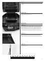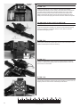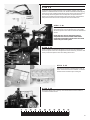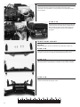
1
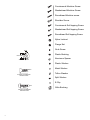
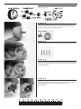
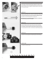
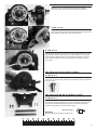
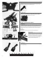
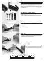
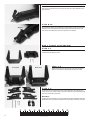
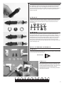
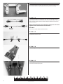
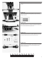
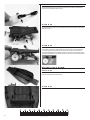
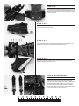
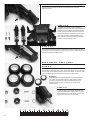
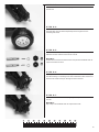
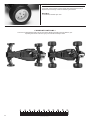
MODEL 3701
MODEL 2401
REV 030128
ASSEMBLY MANUAL
INTRODUCTION:
Below is a list of other tools and supplies you may need for maintenance
and repair of your model:
Thank you for purchasing a Traxxas product. The Rustler and Bandit
deliver pro-level racing technology and performance. The transmission
is a quiet and efficient 3-gear design complete with ball bearings.
The planetary gear differential provides proven durability and lowmaintenance operation. A slipper clutch is included to prevent tire spin.
The four-wheel independent suspension uses oil-filled shocks on the front
and rear for extreme amounts of suspension travel and bump absorption.
The shocks are fully adjustable so the model will have superb control over
rough terrain.
Philips screwdrivers, #1 & #2
Flat blade screwdriver (.25 inches wide)
Small, flat-blade, jeweler’s screwdriver
Pliers, locking (such as Vise Grips) & needle nose
Hobby knife
Superglue (such as “Zap” brand)
Paper plates and Shop rags or paper towels
Tape, masking and electrical
Machine oil such as “3 in 1” Oil™
This manual details the assembly of both the Rustler and the Bandit. If you
purchased a model that is Ready-To-Run, this manual will aid you in
disassembling and rebuilding the model during normal maintenance and
repair procedures. This manual will also acquaint you with the model’s
many different components and its mechanical operation.
Paint and other chemicals needed to finish the body are not included.
These items can be purchased from your hobby dealer. There is a section
in the operating instruction manual which provides tips for painting and
detailing the body. Instructions on installing the wing on the Bandit are
also included in the operating instruction manual.
Look over the manuals and examine the model carefully before opening
any of the parts bags included in the kit. If for some reason you think the
model is not what you wanted, then do not continue any further. Your
hobby dealer absolutely cannot accept a model for return or exchange
which has been run or contains open bags. Please read the separate
Operating Instructions manual before attempting to drive your
new model.
If you have any questions about your Rustler or Bandit, call Traxxas’
technical support department at 1-888-TRAXXAS (U.S.A. residents only,
outside U.S.A. call 972-265-8000). Technical support is available Monday
through Friday, from 8:30am to 9:00pm central time. We hope that you
will enjoy your new Traxxas model. Technical assistance is also available
thru our website at www.Traxxas.com 24 hours a day. E-mail Traxxas at
[email protected]
ASSEMBLY HINTS:
To assemble this kit, you’ll need a large flat working area where you will
have plenty of room to build. Be sure it’s someplace where you can leave
your work spread out and not in the way when you want to take a break
from the assembly. Allow yourself plenty of time to build this kit, assembly
time is going to vary with each individual. Experienced builders may only
need 4-5 hours to assemble this kit, while others may spend an entire
weekend on it. You should feel comfortable with taking as much time as
you need to properly build and set-up your model. The race, after all, is on
the track, not the workbench.
If you’ve been exploring the contents of your kit box, you’ve noticed many
bags of small parts. Open only one bag at a time. To keep the parts
organized, use small paper plates or several large plastic plates with
partitions to contain the parts. Label the paper plates and then pour the
contents of the bags onto them. This puts the parts out in the open where
you can find them easily. The plates also prevent small parts from rolling
off the table.
While it is possible to assemble your kit just by following the pictures,
please read the text next to each photo. The text contains important
information such as screw sizes and part numbers. Also, pay attention to
the “NOTE” which follows some steps.
Before you attempt to run your newly-built model, please read all of the
instructions and precautions included in the operating instruction manual.
Remember, as you assemble your Traxxas model, you are not alone. If you
have any questions or run into difficulties, call the Traxxas’ technical support department at 1-888-TRAXXAS (872-9927). Customers outside U.S.A
call 972-265-8000. Technical support is available Monday through Friday,
from 8:30am to 9:00pm central time.
TOOLS YOU WILL NEED:
Some of the tools which you may need in the maintenance and repair of
your model have been provided for you, they include:
Wrenches, 4-way wrench, hex wrenches (1.5mm & 2.0mm)
u-joint assembly tool
RADIO SYSTEM INSTRUCTIONS:
The radio system is not provided in the unassembled kit. Towards the end
of the assembly process, there are photos demonstrating a typical, twochannel, radio system installation. Before you begin installing your radio
system, it is necessary to locate the center (neutral) position of the
steering and throttle servos. Connect the steering servo to the channel 1
terminal and the throttle servo to the channel 2 terminal in the receiver.
Connect the thin red and black wires from the mechanical speed control
to the “batt” terminal in the receiver.
Place fresh “AA” batteries in the transmitter and turn the power switch on.
Turn the throttle and steering trim adjustments on the transmitter to the
center “0” position. Plug a freshly-charged battery pack into the speed
control. The servos will jump to their center position. Now, unplug the
battery pack and turn off the transmitter. Disconnect all of the radio
components and set them aside. Be careful not to move the servo shafts
when installing the servos into your model.
IMPORTANT: On the Traxxas mechanical speed control, the red wire is
positive and the black wire is negative. Your mechanical speed control is
compatible with Futaba and most other brands of radio equipment.
However, some brands of receivers have reversed positive and negative
input terminals. If you connect the Traxxas speed control to one of these
receivers without changing the wiring, the receiver will be severely
damaged. Pay particular attention to the wiring when using
Airtronics/Sanwa and some Novak brand receivers.
Complete instructions for operating the Traxxas TQ radio system are
included in the operating instruction manual. However, you will need to
follow the instructions that came with your particular radio system.
WARRANTY STATEMENT:
Every effort has been made in component design and material selection
to make your model as durable as possible and still maintain a weight
consistent with good handling.
Because this model is intended for high-speed operation under severe
conditions, no warranties are expressed nor implied relating to the
longevity of the parts.
If you find that a part has a defect in materials or workmanship, please
return it to us BEFORE IT IS USED, and we will gladly replace it.
Damage caused by excessive force, abuse, neglect or failure to adhere
to the precautions outlined in the literature contained with your model
will void the warranty.
HARDWARE DESCRIPTION:
The drawings that follow are provided to help you identify the many
different sizes and types of hardware that are used in the assembly of
this model. Note the difference between the length measurements of
the roundhead and countersunk screws. A ruler is provided at the
bottom of each page to measure the length of the screws in millimeters.
2
Countersunk Machine Screw
Washerhead Machine Screw
Roundhead Machine screw
Shoulder Screw
Countersunk Self-tapping Screw
Washerhead Self-tapping Screw
Roundhead Self-tapping Screw
Nylon Locknut
Flange Nut
Grub Screw
4mm
Plastic Bushing
6mm 3mm
3x6x4mm Spacer
Aluminum Spacer
Plastic Washer
Metal Washer
3mm
12mm
3x12mm Countersunk
machine screw
Teflon Washer
Split Washer
E-Clip
3mm
12mm
3x12mm Roundhead
machine screw
3
Oilite Bushing
STEP A-1
This drawing is provided to help you identify the parts of the planetary
differential by name.
STEP A-2
Locate the main differential gear and one of the sun gears. Apply silicone
grease to the base of the output shaft of the sun gear. Insert the sun gear
through the center of the main differential gear.
OUTPUT SHAFT
STEP A-3
Insert the four planet shafts into the holes inside the main differential gear.
STEP A-4
Squeeze a small amount of the silicone grease into the center hole of each of
the four planet gears. Slide the planet gears onto the planet shafts inside the
main differential gear.
STEP A-5
Apply grease to the remaining sun gear and the small sun gear alignment
shaft. Install the alignment shaft into the center of the first sun gear (inside
the differential). Now, install the remaining sun gear over the
alignment shaft.
4
STEP A-6
Squeeze a liberal amount of silicone grease inside the main differential gear.
Locate the side cover plate. Notice that the two alignment notches, in the
side cover plates (arrows) are different sizes. Install the cover plate over the
sun gear shaft and onto the main differential gear. Align the notches. Secure
the side cover plate with four 2.6x8mm countersunk machine screws located
in the machine screw bag.
STEP A-7
Locate the top gear shaft, 9.5mm roll pin, the 22-tooth steel top gear and two
5x8x0.5mm teflon washers. Insert the roll pin, bevelled end first, into the hole
in one end of the top gear shaft. Use a pair of pliers to carefully squeeze the
pin through the shaft until it is centered in the shaft. Be careful not to leave
plier marks, or cause other damage to the top gear shaft.
NOTE: If the top gear and shaft assembly have been pre-assembled for
you at the factory, continue on to step A-9.
STEP A-8
Slide the top gear onto the top gear shaft until the notch in the gear fits over
the roll pin. Make sure that the roll pin does not protrude far enough on
either side to interfere with the gear mesh. Because the top gear press fits
onto the shaft, it may be necessary to place the top gear over the open jaws
of a vise and use a plastic hammer to tap the shaft through the gear. Do not
use a metal hammer for this task, or the shaft may be permanently damaged.
STEP A-9
Locate the left and right gearbox halves. Insert a 5x11mm ball bearing into
each of the 4 holes in the gearbox. The ball bearings are located in bag H.
STEP A-10
Slide a 5x8x0.5mm teflon washer over each end of the top gear shaft.
The washers are located in bag H.
5
STEP A-11
Apply a light coating of silicone grease on the teeth of the top gear. Install
the top gear shaft into the left gearbox half as shown.
STEP A-12
Locate the idler gear shaft and install it into the left gearbox half as shown.
Do not grease the ends of the shaft where they insert into the plastic. Slide a
5x8x0.5mm teflon washer over the idler gear shaft.
STEP A-13
Locate the idler gear. Press a 5x11mm ball bearing into each side of the gear.
Apply a light coating of silicone grease to the gear teeth.
STEP A-14
Slide the idler gear over the idler gear shaft, followed by another 5x8x0.5mm
teflon washer.
STEP A-15
Locate the main-differential assembly. Apply a light coating of grease to the
teeth on the gear. Install the differential into the left gearbox housing,
pushing the output shaft through the ball bearing.
NOTE: The side of the differential with the screws should face down
toward the left gearbox half (as shown).
6
STEP A-16
Slide the right gearbox half over the top gear, idler gear, and differential gear
shafts. Hold the gearbox halves together tightly with your fingers and spin
the top gear shaft to ensure that there is no binding. Slight amounts of
roughness will be eliminated after the gearbox has been broken-in from use.
STEP A-17
#1
#2
#3
Fasten the gearbox halves together by installing four 3x23mm roundhead
machine screws in locations indicated by arrow #1, 3x30mm for arrow #2,
and 3x20mm for arrow #3. Do not use an electric screwdriver or overtighten the screws. The two remaining holes in the gearbox will be used
later in the assembly process to mount the speed control resistor pack.
#1
#1
#1
DRIVE SHAFT ASSEMBLY:
STEP A-18
Locate the differential output yokes, and two 3x12 yoke pins.
STEP A-19
Press one of the output yokes onto one of the differential output shafts.
Align the flat areas inside the yoke with the flat areas on the shaft. Repeat
step on the opposite side with the remaining yoke.
STEP A-20
Secure both yokes with a 3x12 yoke pin. The shaft of the yoke pin must enter
through the hole in the output shaft. Thread the yoke pin into the output
yoke until the yoke pin is flush with the outside of the output yoke.
7
STEP A-21
Locate the two external-splined halfshafts, two metal u-joint balls, and the
u-joint assembly wrench.
External-spline (male)
Internal-spline (female)
BANDIT:
The Bandit halfshafts are shorter than the ones pictured; however, the
assembly process is identical.
STEP A-22
Begin by inserting one of the pins of the metal u-joint ball into the externalsplined halfshaft.
STEP A-23
Use the u-joint assembly wrench, as shown, to insert the opposite pin into
the halfshaft. Exert force down and to the left (as shown in the photo), in
order to spread both sides of the halfshaft equally by. Repeat for the
remaining external-splined halfshaft.
STEP A-24
Insert one of the remaining u-joint pins into the differential output yoke.
STEP A-25
Use the u-joint assembly wrench to insert the remaining pin into the
differential output yoke. Again, spread both sides of the differential output
yoke while pressing the pin into the hole. Be careful not to spread the
output yoke too far, or breakage could result. Repeat the last two steps
for the other side.
8
SLIPPER CLUTCH INSTALLATION:
STEP A-26
Locate the 84-tooth spur gear, two pressure plates, two notched, pressure
rings, six friction pegs, the spur gear bushing, the slipper tension spring and
a 4mm locknut.
BANDIT:
Use the 78-tooth spur gear instead of the 84-tooth spur gear that is pictured.
STEP A-27
Install a pressure plate onto the top gear shaft with the small, gold pin facing
out. Place one of the pressure rings over the pressure plate. Install the
pressure ring with the flat side against the pressure plate. Align the notch in
the pressure ring with the pin.
STEP A-28
Slide the spur gear bushing onto the top gear shaft. Install the spur gear. It
should fit snugly onto the bushing. Insert a friction peg into every other,
inner hole on the spur gear (as shown below). Place the other pressure ring
on top of the spur gear (beveled side against the spur gear pegs).
STEP A-29
Install the other pressure plate as shown. Align the pin in the pressure plate
with the notch in the pressure ring. Slide the spring over the top gear shaft
and secure the assembly with the 4mm locknut.
MOTOR INSTALLATION:
STEP A-30
Locate the motor, two 3x8mm washerhead machine screws, the 18-tooth
pinion gear, and a 3mm grub screw.
BANDIT:
Use the 25-tooth pinion gear instead of the 18-tooth pinion gear that is pictured.
9
STEP A-31
Fasten the motor to the transmission with the two 3x8mm
washerhead machine screws. Do not tighten the screws yet.
STEP A-32
Slide the pinion gear (teeth first) onto the motor shaft as shown.
Insert the grub screw into the pinion gear and tighten it against the
flat of the motor shaft with a 1.5mm Allen wrench.
STEP A-33
Slide the motor forward so that the pinion gear meshes with the spur gear.
Adjust the gear mesh by inserting a piece of thin note paper into the gear
mesh and then tightening the motor screws. When the paper is removed,
there should be a slight amount of play between the spur gear and the
pinion gear.
INSTALLING THE GEAR COVER:
STEP A-34
Locate the gear cover and two 3x5mm roundhead machine screws. Snap the
gear cover over the spur gear and secure it with the two 3x5mm roundhead
machine screws.
INSTALLING REAR CAMBER LINKS:
STEP A-35
Locate the rear shock tower, two 90mm camber links, two 3x12x4mm
shoulder screws (the 4mm dimension refers to the length of the shoulder),
two 3x12mm roundhead self-tapping screws, and two 3mm flat metal
washers. The shoulder screws are located in bag H.
Shoulder screw
BANDIT:
The rear camber links are 65mm overall length.
10
STEP A-36
Fasten the two rear camber links to the lower holes in the shock tower with
the 3x12mm shoulder screws and 3x6mm flat washers. Insert the washer
between the shoulder screw and the shock tower.
STEP A-37
Position the rear shock tower on top of the gearbox as shown. Fasten the
shock tower to the gearbox with two 3x12mm roundhead self-tapping
screws. The transmission assembly is now complete.
REAR SUSPENSION ARMS:
STEP B-1
Locate the left and right rear suspension arms, the rear stub axle carriers,
two 46mm screw pins, two 28mm screw pins, two 3x12mm ball screws, four
5x8mm oilite bushings, and two 3x6mm flat metal washers. The washers are
located in bag H. Remove any mold flashing that may still be attached to
the parts.
BANDIT:
The Bandit rear suspension arms are shorter than the Rustler arms.
STEP B-2
“R”
Left
Right
The suspension arms are labeled L and R to
designate left and right. Position the left and right
suspension arms onto the mounts of the gearbox
as shown. Insert a 46mm screw pin through the
pivot points on each suspension arm. Tighten the
screw pins until they are snug, but not tight
enough to bind the suspension arm.
Screw pin
STEP B-3
Insert the oilite bushings into the stub axle carriers. Place a drop of 3-in-1
Oil™ on each bushing.
11
STEP B-4
Position a stub axle carrier, as shown, on the end of each of the suspension
arms. Note that the stub axle carrier has two pivot points. Use the top hole.
Insert a 28mm screw pin through the pivot points on each arm. Do not
overtighten. Slide a 3x6mm washer over each of the 3x12mm ball screws.
Insert the screws into the fourth hole (counting from the inside out) of each
rear suspension arm.
Washer
DRIVE SHAFT COMPLETION:
STEP B-5
Locate the two internal-splined halfshafts, the two stub axles, two metal
u-joint balls, and the u-joint assembly wrench (leftover from bag A).
STEP B-6
Insert one pin of the metal u-joint ball into one side of the internalsplined halfshaft.
STEP B-7
Use the u-joint assembly wrench to insert the opposite pin into the halfshaft.
Try to exert force down and to the left (as viewed in the photo), in order to
spread both sides of the halfshaft yoke equally.
STEP B-8
Insert one of the remaining u-joint pins into the stub axle
yoke. Use the u-joint assembly wrench to insert the opposite
pin into the stub axle yoke. Exert force down and to the left
in order to spread both sides of the stub axle yoke equally.
12
STEP B-9
Insert the external-splined halfshaft into the internal-splined halfshaft.
Next, insert a greased stub axle through the stub axle carrier. Repeat for the
opposite side.
STEP B-10
Attach the free end of the camber link to the stub axle carrier with a 3x12mm
shoulder screw and a 3x6mm flat metal washer. Repeat for the other stub
axle carrier and camber link. The rear suspension is complete.
Washer
BAG C FRONT SUSPENSION:
STEP C-1
Locate the front bulkhead, the front shock tower, and two 3x15mm
washerhead self-tapping screws.
STEP C-2
Front View
Back View
Attach the shock tower to the back of the front bulkhead
with the two 3x15mm washerhead self-tapping screws.
STEP C-3
Locate the two front suspension arms, the left and right caster blocks, two
40mm screw pins, and two 24mm screw pins. Remove any mold flashing that
may have remained on the parts.
BANDIT:
The Bandit front suspension arms are slightly shorter than the Rustler arms. The
Bandit also uses two 31.5mm suspension pins with E-clips instead of screw pins.
13
STEP C-4
Attach the front suspension arms to the bulkhead by inserting a 40mm screw
pin through each pivot point. Tighten the screw pins until they are snug, but
not tight enough to bind the part.
STEP C-5
The caster blocks are labeled L and R for left and right. Position the right
caster block in the right suspension arm as shown. Insert a 24mm screw pin
through the pivot point and tighten. Repeat for the left side.
BANDIT:
Install the caster blocks with the 31.5mm suspension pins and e-clips.
STEP C-6
Locate the steering blocks, four 5x8mm oilite bushings, two 2.5x31.5mm
suspension pins, and four e-clips.
STEP C-7
Press two 5x8mm oilite bushings into each of the two
steering blocks. Snap an e-clip into one of the grooves on
each suspension pin.
STEP C-8
Position a steering block in the right caster block, as shown.
Insert a 2.5x31.5mm suspension pin through the pivot
point. Secure the suspension pin by snapping an e-clip into
the other groove. Repeat for the other side.
14
STEP C-9
Locate the two 78mm front camber links, four 3x12mm shoulder screws, and
four 3x6mm flat metal washers.
BANDIT:
The front camber links are 75mm overall length.
STEP C-10
Attach one end of each camber link to the front
shock tower by inserting the 3x12mm shoulder
screw through the camber link, sliding a 3x6mm
flat metal washer over the shoulder screw, and
screwing the shoulder screw into the front
shock tower.
STEP C-11
Attach the outer end of each camber link to the caster blocks with the
remaining two 3x12mm shoulder screws and 3x6mm flat metal washers.
Washer
STEP C-12
Locate the front bumper and two 4x12mm countersunk machine screws.
Attach the front bumper to the bottom of the front bulkhead. The front
suspension assembly is now complete.
Limiter
BAG D SHOCK ASSEMBLY:
STEP D-1
Your model is equipped with long front shocks and XX-long rear shocks.
Empty the shock parts from bag D onto a plate and separate the parts into
like groups. Build only one shock at a time. You will only use the limiter,
pictured in the drawing, when building each of the XX-long, rear shocks.
The long, front shocks do not require the use of the limiter.
15
STEP D-2
Lubricate a rubber O-ring by putting a drop of silicone oil on it. Push the
O-ring into the bottom of the shock body.
STEP D-3
Locate the 3x6x2.5mm spacer and remove any mold flashing. Insert the
spacer, rounded edge first, into the bottom of the shock body and press
firmly so that it compresses the rubber O-ring.
STEP D-4
Lubricate another O-ring and insert it into the bottom of the shock body, on
top of the spacer.
STEP D-5
Secure the seal assembly by screwing the bottom cap onto the bottom of the
shock body. Tighten the cap firmly with your fingers only. Do not use pliers
to tighten the cap.
3x6x1.5mm
Limiter
STEP D-6
E-clip
Locate the shock rods. Use needle nose pliers to insert an e-clip into the
bottom groove on each shock rod. On the two longer rods, slide a
3x6x1.5mm limiter onto each rod.
BANDIT:
Do not use the limiters in the rear shocks of the Bandit. Instead, use the limiters
in the FRONT shocks (on the shorter shock rods).
16
STEP D-7
Place a piston head on the shock shaft. Use the two-hole pistons
with the factory-supplied, 40-weight shock oil. Secure the piston
head with a small e-clip.
STEP D-8
Place a drop of oil on the threads of one of the shock rods (use the longer
rods in the longer shock bodies (rear). Insert the rod into the shock body,
threaded end first. Move the threads carefully past the seals.
STEP D-9
Grip the shock shaft, just above the threads, with the tips of your needlenose
pliers and screw on a plastic rod end. Be sure to use the four short rod ends
when assembling the shocks. Never grip the shock shaft with pliers any
further up on the shaft.
STEP D-10
Carefully insert a rubber diaphragm into one of the upper shock caps. The
rubber dome should face out (down into the shock). Use the end of the
1.5mm Allen wrench to carefully seat the edges of the diaphragm in the cap.
STEP D-11
Pull on the shock rod so that the piston is at the bottom of the cylinder. Fill
the shock with oil until it is about 3/4 full. SLOWLY move the piston up and
down, while twisting it in the cylinder (always keeping it submerged in oil) to
release the air bubbles. Be careful not to squirt oil in your face by moving the
piston too rapidly. Finish filling the shock until the oil level is 1.5mm from the
top edge of the shock body.
17
STEP D-12
Allow any remaining air bubbles to surface, then screw on the upper shock
cap. Tighten the upper cap only finger tight. Overtightening may damage
the rubber diaphragm and cause leakage. Exercise the shock. It should
operate smoothly and quietly. If it squeaks, remove all trapped air bubbles in
the shock body by removing the upper cap and allowing the bubbles to
surface and break.
STEP D-13
Locate the upper and lower spring retainers, the appropriate length springs
(longer for the XX-long rear shocks, shorter for the long front shocks), an
assortment of spring pre-load spacers, and two hollow ball connectors
(not pictured).
STEP D-14
Slide the upper spring retainer over the shock cylinder, followed by the
appropriate length spring, and then the lower spring retainer. The spring preload spacers are used to adjust the ride height of the model by inserting
them between the upper spring retainer and the upper shock cap. The preload spacers snap over the shock bodies without having to remove the
spring. Snap a metal hollow ball connector into the rod ends of the two
shorter (long front) shocks (pictured). Repeat steps D-1 through D-15 for the
three remaining shocks.
BAG E STEERING ASSEMBLY:
STEP E-1
Locate the two bellcranks, the drag link, two chrome 3x12mm shoulder bolts,
and four 5x8x2.5mm white bushings.
Shoulder bolt
STEP E-2
Insert the bushings into the top and bottom of the
bellcranks by placing the bushing on the table and
pressing the bellcrank firmly onto it. You will need to
trim any flashing from the bushings and the
bellcranks before insertion. The bushings should be
flush with the bellcrank.
18
STEP E-3
Attach the drag link to the bellcrank with the two 3x12mm shoulder bolts, as
shown. Make sure the assembly operates smoothly without binding.
STEP E-4
78mm
Locate the two 62mm turnbuckles (tie rods), four long rod ends, and four
hollow ball connectors. Screw the rod ends onto the turnbuckles so that each
has a center-to-center distance of 78mm. Snap the hollow ball connectors
into the rod ends.
NOTE: The turnbuckle has reverse threads on the long side. The rod end
tightens counter-clockwise on the reverse threads.
Reverse
threads
BANDIT:
The center-to-center distance should be 76mm.
STEP E-5
Fasten the tie rods to the bellcrank arms, as shown, with two 3x12mm
washerhead machine screws.
STEP E-6
Locate the upper chassis plate and two 5x8x0.5mm teflon washers.
STEP E-7
Turn the upper chassis plate over and slide a 5x8x0.5mm teflon washer over
each of the bellcrank pivot posts.
19
STEP E-8
Slide the bellcrank assembly over the posts as shown (note photo for exact
assembly).
STEP E-9
Locate two 3mm flat washers and two 3x30mm hex cap screws (shown
below). Place the washers over the shoulder screws and secure the bellcrank
assembly to the posts.
STEP E-10
The steering and throttle servos are not included with the kit. Follow your
radio system’s instructions for “centering” the servos before installing any
servos. Attach the steering servo to the upper chassis plate, exactly as shown,
with four 3x8mm washerhead self-tapping screws.
STEP E-11
Locate the servo saver and adapters, the 28mm threaded rod, two long rod
ends, two hollow ball connectors, one 3x15mm washerhead machine screw,
one 3x12mm washerhead machine screw and one 3mm locknut.
Adapters
Servo Saver
STEP E-12
46mm
Screw the rod ends onto the threaded rod, an equal number of turns each, so
that there is a center-to-center distance of 46mm. Snap the two hollow ball
connectors in to the holes on the rod ends. This assembly will now be
referred to as the steering rod.
20
STEP E-13
Attach the steering rod to the servo saver with the 3x15mm washerhead
machine screw and the 3mm locknut.
STEP E-14
Attach the steering rod to the right bellcrank with the 3x12mm washerhead
machine screw.
STEP E-15
Position the bellcranks so that they are pointing straight ahead, and fasten the
servo saver to the servo output shaft. Use the screw size recommended by
your radio system instructions to secure the servo saver. Use the correct
output shaft adapter when installing the servo saver onto the steering servo.
The steering assembly is complete. Check it at this time for smooth operation.
BATTERY HOLD DOWN:
STEP E-16
Locate the chassis, the battery hold-down plate, the two metal posts, two
body clips and speed control mount.
STEP E-17
Screw the posts into the chassis as shown.
21
STEP E-18
Place the battery hold-down plate over the posts and secure it with the two
body clips.
STEP E-19
Position the speed control mount on the chassis as shown. Secure it with two
3x10 washerhead self-tapping screws.
RECEIVER:
STEP F-1
The receiver is part of the radio system and is not included in the kit. If you
are using a Traxxas receiver, fasten the tabs on the receiver to the posts
molded in the left side of the chassis. Use two 3x6mm washerhead selftapping screws. Mount all other receivers by using double-sided servo tape.
Clean the surfaces of the receiver and the chassis with rubbing alcohol
before applying the servo tape. Route the antenna wire under the receiver.
STEP F-2
Insert the antenna wire through the antenna tube, and then insert the
antenna tube into the slot in the chassis. Do not cut the antenna wire to
shorten it. The antenna tube and the antenna tip are in the instruction bag.
STEP F-3
Fold the excess antenna wire over the end of the antenna tube and secure it
with the antenna tip.
22
OUTPUT
SHAFT
THROTTLE SERVO:
STEP F-4
Locate your throttle servo (not included in the kit) and four 3x8mm
washerhead self-tapping screws. Center your throttle servo as described in
your radio system’s instructions. Install the throttle servo in the chassis.
Position the output shaft as shown and secure the servo with the four
3x8mm washerhead self-tapping screws. Route the throttle servo cable
neatly to the receiver and plug the connector into the channel 2 receptacle.
TRANSMISSION INSTALLATION:
STEP F-5
Locate the transmission assembly, two 3x12mm countersunk self-tapping
screws, four 4x12mm countersunk machine screws, and two 3x12mm
roundhead self-tapping screws.
STEP F-6
Place a piece of electrical or plastic tape over the hole in the bottom of the
gearbox. This will prevent dirt from entering.
STEP F-7
Position the transmission on the rear of the chassis as shown. Insert two
3x12mm roundhead self-tapping screws, through the bottom of the rear
shock tower, into the chassis.
STEP F-8
#2
#2
#1
23
Turn the chassis over and insert a 4x12mm countersunk machine screw into
each location indicated by the #1 arrows. Insert a 3x12mm counter-sunk selftapping screw into each location indicated by the #2 arrows.
SPEED CONTROL:
STEP F-9
Locate the rotary mechanical speed control, resistors, resistor cover, two
3x23mm roundhead machine screws, two 3x12mm washerhead self-tapping
screws and a 3x12 roundhead self-tapping screw. Remove the speed control
from the bag and untangle the wires. In the photo, the speed control is
shown in its neutral position (between forward and reverse). It should be in
this position when turned over and pressed onto the throttle servo.
STEP F-10
Position the speed control on top of the throttle servo
and push it down onto the throttle servo output shaft.
Secure the speed control with two 3x12mm washerhead
screws.
NOTE: The servo horn on the speed control is
compatible with Traxxas/ Futaba radios. When
using other brand radios, use the servo horn which
comes with your radio system.
STEP F-11
Insert a 3x12mm roundhead self-tapping screw into the shock tower just
above the speed control. Do not tighten the screw all the way, as shown. This
screw prevents the speed control from lifting off the servo.
STEP F-12
Place the two resistors in the aluminum cover, as
shown. Fasten the back with a 3x6mm roundhead
machine screw and 3mm nylon locking nut
STEP F-13
Attach the resistor pack to the top of the transmission with two 3x23mm
roundhead machine screws.
24
STEP F-14
Insert the white and blue resistor wires through the square hole in the rear
shock tower. Reconnect the wires to the resistor pack. They can be
connected in any combination, so long as there is one white and one blue
wire per resistor.
STEP F-15
Insert the motor wires through the shock tower and
connect them to the motor (red-to-red and black-toblack). Route the speed control cable neatly to the
receiver and plug the connector into the battery
receptacle.
FRONT BODY MOUNT:
BANDIT:
Steps F-16 through F-18 are for the Rustler only. Please skip to Step F-19.
STEP F-16
Locate the front body mount, two 25mm body posts, two 3x8mm washerhead
self-tapping screws, and two 3x10mm washerhead self-tapping screws.
STEP F-17
Fasten the body posts to the body mount with the two 3x8mm washerhead
self-tapping screws. Study the photo carefully to ensure correct assembly.
STEP F-18
Fasten the body mount to the back of the front shock tower with two
3x10mm washerhead self-tapping screws.
25
FRONT END ASSEMBLY:
STEP F-19
Position the front suspension assembly onto the front of
the chassis as shown. Attach the front suspension to the
chassis with three 4x12mm countersunk machine screws
from the underside.
STEP F-20
Locate the upper chassis plate assembly, two 4x15mm countersunk machine
screws, two 3x12mm washerhead machine screws and two 3x12mm
countersunk self-tapping screws.
STEP F-21
Position the upper chassis plate assembly on the chassis as shown. Attach it
in the front with the two 4x15mm countersunk machine screws and in the
rear with the two 3x12mm countersunk self-tapping screws.
STEP F-22
Attach the outer ends of the tie rods to the steering blocks with the two
3x12mm washerhead machine screws.
SHOCK INSTALLATION:
STEP F-23
Locate the two rear XX-long shocks (the two longest
ones), two 3x12mm shoulder screws, and two 3x6mm flat
metal washers. Insert the shoulder screws through the
shock caps and then slide a 3x6mm flat metal washer
over the end of each shoulder screw. Screw the shoulder
screws into the holes in the shock tower.
26
STEP F-24
Snap the bottom of each rear shock over the ball screws in the rear
suspension arms.
STEP F-25
Locate the front shocks, the two remaining
3x12mm shoulder screws, two 3x6mm flat metal
washers, and two 3x15mm roundhead machine
screws. Attach the shocks to the shock tower by
inserting the shoulder screws through the shock
caps, sliding a 3x6mm flat metal washer over
each shoulder screw and screwing the shoulder
screws into the front shock tower.
STEP F-26
Attach the front shocks to the front suspension arms by inserting the end of
each shock into the suspension arm and securing it in the outside holes with
3x15mm roundhead machine screws.
BAG G WHEELS, TIRES, AXLES:
STEP G-1
Locate the front and rear tires and wheels. The front Rustler wheels can be
identified by their deeper offset (dish). Stretch the ribbed front tires over the
front wheels and the spiked rear tires over the rear wheels. On all tires, make
sure the bead of the tire is fully seated in the groove of the wheel.
BANDIT:
Stretch the front and rear knobby tires over the front and rear
rims, make sure the bead of the tire is fully seated in the rim.
You may glue the tires by pulling the bead back with your
thumb and placing a drop of superglue in several places
around the tire.
STEP G-2
Locate two axle pins, hex hubs, 4mm locknuts
and 5x8x1.0mm plastic washers. Slide one of the
plastic washers over a stub axle. Now, insert the
axle pin into the hole in the stub axle.
27
STEP G-3
Slide a hex hub over the stub axle, aligning the stub axle pin with the slots in
the hex hub.
STEP G-4
Slide a rear wheel over the stub axle, turn until it locks into the wheel. Secure
the wheel with a 4mm locknut. Repeat steps G-2 through G-4 for the
remaining rear wheel.
STEP G-5
Locate the front axles, the remaining two axle pins and hex hubs, two
5x8x0.5mm teflon washers and two 4mm locknuts.
BANDIT:
The Bandit front axles are shorter than the ones pictured. The Bandit does not
require hex hubs in the front.
STEP G-6
Liberally coat the front axles with silicon grease. Insert a front axle through
the oilite bushings in a steering block. Slide a 5x8x0.5mm teflon washer over
the front axle. Insert an axle pin through the hole in the axle.
STEP G-7
Slide a hex hub onto the front axle, aligning the axle pin with the slots in the
hex hub.
BANDIT:
Skip to Step G-8. The Bandit does not require the hex hub.
28
STEP G-8
Slide a front wheel over the front axle. Turn until it locks into the front wheel.
Secure with a 4mm locknut. Hold the wheel when tightening the locknut.
Repeat steps G-6 through G-8 for the remaining front wheel.
BANDIT:
On the Bandit, use 4mm nylon nuts.
CONGRATULATIONS!
Your kit is now assembled! All that is left are a few minor details and painting the body. Refer to your
“operating instructions” manual to get your model set and ready to drive!
29