1
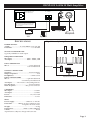
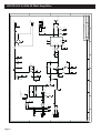
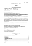
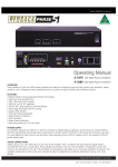
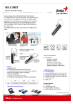
www.altronics.com.au
®
A 4016 15W Public Address Amplifier
OPERATING INSTRUCTIONS
Distributed by Altronic Distributors Pty. Ltd. Perth. Western Australia.
Phone: 1300 780 999 Fax: 1300 790 999
Internet: www.altronics.com.au
Proudly Assembled in Australia
REDBACK A 4016 15 Watt Amplifier
OVERVIEW
TROUBLE SHOOTING
The Redback A4016 PA amplifier is super compact and
ideally suited to smaller PA system installations.
Designed around the National TDA1519 IC it offers
virtual "destruction proof" operation even under sever
misuse such as over voltage, over temperature, over load
and short circuit speaker line conditions. The amplifier is
extremely stable even when microphone and speaker
cables are run together over long distance. The unit will
automatically shut down when overloaded and will
restore to normal operation when the fault condition is
removed.
NO POWER
(Power LED light does not illuminate)
Check mains fuse. Only replace with M205, 240V AC 800mA
rated fuse.
DISTORTED OUTPUT
Check that the speaker type is correct for the output that you
are using. Check for any short circuits on the speaker line.
VERY LOW OUTPUT
Make sure that the input is the correct level (check for shorted
connectors). Check for any short circuits on the speaker line.
CONTINUALLY BLOWS FUSES
Make sure that the speaker line is not shorted. Check also
speaker types, ratings and if on correct output.
AMPLIFIER KEEPS ON CUTTING IN & OUT
Check speaker types, ratings and for any short circuits on the
speaker line.
The A4016 can be used as a stand alone/ bench mount
amplifier or can be rack mounted when used in
conjunction with optional hardware. Up to two units can
be fitted side by side within 1RU of rack space. The
amplifier can be operated from either 12-14V DC or 240V
AC . This versatility makes it ideal for mobile
applications such as tour buses, boats etc.
MOUNTING KITS
FEATURES
• 15W RMS Output
• 1 balanced XLR and unbalanced jack mic input
• 1 Auxiliary input
• 4-16Ω output
• 240VAC / 12-14VDC operation
• Headphone Socket
H 4990 Enables 2 x A 4016 amplifiers to be housed in a
single 44mm 1RU rack space.
H 4991 Under dash or under desk mounting bracket.
H 4992 Infill blanking panel, where only one
A 4016 is rack mounted.
12V 4-16ohm
DC Output
M ade in Australia by
Altronic Distributors Pty Ltd
+ -
L
+ -
2
1
3
R
AC Fuse (M 205 800m A)
1
3
2
Aux Input
M ic Input
6
7
5
4
Legend
Fig. 1: Rear panel layout.
1
Snap in AC Fuse
4
4-16 Ohm Output
2
IEC Mains Socket
5
Headphone Socket
3
12V DC Input
6
Aux Input (RCA)
Mic
Input
6
4
2
10
Microphone Input (XLR)
15W
4015 15W
A 4016
Amplifier
6
4
8
0
REDBACK
Aux
Mic
7
2
8
0
On
On
10
Power
1
2
Fig. 2: Front panel layout.
Page 2
3
4
Legend
1
Microphone Socket
4
Power LED
2
Microphone Level
5
Power Switch
3
Auxilliary Level
5
REDBACK A 4016 15 Watt Amplifier
Made in Australia by
Altronic Distributors Pty Ltd
AC Fuse (M205 800mA)
Mic Input
12V 4-16ohm
DC Output
+ -
L
+ -
2
1
3
R
Aux Input
Note: Microphone XLR input at rear is
balanced. A 6.35mm unbalanced jack on
the front panel can also be used at the same
time, however this will result in mixed audio
from both inputs.
+
Battery
12V
SPECIFICATIONS
CD Player
Microphone
Speaker
Fig. 4: Internal fuse replacement
POWER OUTPUT
A 4016:...........................15 watts RMS @ 13.8V into 4Ω
Distortion:..................................................< 3% @ 1kHz
SIGNAL TO NOISE RATIO
Typically 75dB below rated output.
FREQUENCY RESPONSE
Mic input: .......................................50Hz - 10kHz, -3dB
Aux input:.......................................60Hz - 15kHz, -3dB
INPUT SENSITIVITY
Mic 1: .....................................................1.5mV balanced
1.5mV unbalanced
OUTPUT CONNECTORS
Speakers:...............................................Screw terminals
Output impedance: ..................................................4-16
Headphones:.............................................3.5mm socket
INPUT CONNECTORS
Mic 1: ...............................................3 pin XLR balanced
or 6.35mm jack unbalanced
Aux input:..............RCA stereo socket, bridged mono
12V DC power:.....................................Screw terminals
240V AC power:..........................IEC power connector
DC Fuse 4A
Speaker Fuses 1A x 2
CONTROLS
Mic input:............................................................Volume
Aux input: ...........................................................Volume
Power: .......................................................On/off switch
Indicators: ..............................................................Power
MISC.
Power supply: ...............................240V AC or 12V DC
Protection: ................800mA AC fuse and 4A DC fuse
1A Speaker Protection fuse
Weight:...................................................................≈2.5kg
Dimensions:.........................≈210W x 130D x 44H mm
Colour:......................................................................Black
*Specifications subject to change without notice
Page 3
A
B
C
D
DRAWN
ENG
1
1
2
3
AGND
R
E
L
S1
RCASTEREO
P1
AXRFEM
PHONEJACK2
S2
R2
R1
C1
1n
1 0k
1 0k
C2
1n
R8
R7
R23
R24
10uF BP
C5
6 80
6 80
6K8
6K8
2
J1
C4
10uF BP
C3
10uF BP
+ C22
100/16V
680R
R18
ON
OFF
1
2
3
1
2
3
+6
R5
10K
R9
10K
5
6
VCC
R10
U2B
LM 833
2 7k
C6
47pF
C24
47pF
PHANTOM POW ER
JUM PER
7
3
RV1
10k
RV2
10k
C7
10
R11
27k
R12
100k
15V
ZD2
LED1
POW ER
R4
4K7
C9
10
VCC
C8
10
4
C18
100n
R17
4K7
4
C10
100
R13
6k8
3
2
VCC
2 7k
VCC
1
ZD1
6v8
R15
4k7
U2A
LM 833
R14
4 7pF
C11
C17
1000
R49
680R
C14
100n
R16 R48
680R 680R
+12
+6
5
C15
2200
5
C12
100nF
C23
100nF
C16
2200
R20
10
R21
10
6
F1
4A
6
C13
100
3
9
1
+12
8
R/R
INV
NINV
M /SS
3
+12
VCC
2
8
4
7
AGND
2
GND
5
Page 4
Date:
File:
A3
Size
Title
OUT2
OUT1
B1
7
7
F3
C20
470n
R22
10
1A
F2
1A
A. 4 0 1 6 a 2
1
2
1
2
P5
24V AC IN
P3
12V DC IN
8
P4
Sheet of
Drawn By:
1
8
Revision
S. M.
1
A
SPEAKER OUT 4-16OHM
1
2
PHONEJACK STEREO SW
P6
A 4 0 1 6 1 5 W AMP
C19
470n
R19
10
C21
47uF 35V
330R 1W
R3
6A DIODE
D1
6-Apr-2005
S:\KITS\..\A4016A2.SCH
Number
6
4
U3
TDA1519C
+
1
A
B
C
D
REDBACK A 4016 15 Watt Amplifier