1
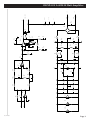
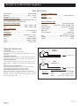
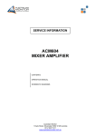
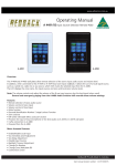
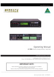
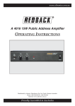
www.altronics.com.au
®
30W Public
Address Amplifier
OPERATING INSTRUCTIONS
A 4020: 30W Desk Mount Amplifier
VOX Muting Adjustments
FEATURES
• 1 balanced microphone input
• 2 auxiliary inputs
• Bass and treble controls (on both microphone and
auxiliary inputs).
• Full 30W RMS output (100V).
• Protection against over-voltage, over current, thermal
run-away and short circuit load.
• Internationally accepted IEC mains socket (240V AC
operation only).
• Stereo RCA sockets for all auxiliary inputs (configured to mono internally allowing standard stereo
equipment to be directly connected).
• Ten year warranty.
CONNECTING UP THE UNIT
Microphone One
Microphone inputs are connected via balanced XLR 3 pin
socket. For connection to the 3 pin XLR sockets refer to
Fig 1.
Auxiliary Inputs
Both auxiliary inputs are connected via standard RCA
sockets.
VOX can be selected ON or OFF on the board via the
internal jumper. This is factory set in the OFF position.
VOX sensitivity is adjusted via trimpot on rear of unit.
Once VOX muting is activated input 1 will override input
2. Both mic 1 and aux 1 inputs will activate the vox muting.
OPERATION
Once all inputs and outputs are connected:
1 Turn bass and treble to midway point.
2 Turn all volume controls to zero.
3 Turn power switch on. Power indicator should illuminate.
4 Turn on microphone or auxiliary input source and
adjust appropriate volume control to desired level.
The microphone and auxiliary for input 1 are mixed
together. Both the mic and auxiliary inputs can be run
together but note there is only the one volume control for
both of these.
Speaker Outputs
Screw terminals are provided for 100V outputs.
Minimum impedance for 100V loads is 333Ω (When only
the 100V output is used).
If more than 30W is used then the unit may shut down
due to overloading.
Distributed by Altronic Distributors Pty. Ltd. Perth. Western Australia.
Phone: 1300 780 999 Fax: 1300 790 999
Internet: www.altronics.com.au
Proudly Assembled in Australia
Doc. BL2085
R23
47k
S4
P 0210
R24
47k
R4
2k2
R14
47k
R13
47k
RV1
100k
S2
P 0210
2
3
1
5
6
C2
1/bp
C1
1/bp
R5
R27
2k2
U3B
TL072
15p
C14
1m
R17
2k2
R16
1k
C3
220p
R15
1k
7
C9
1/bp
D1
4148
C12
100n
R18
22k
3
2
R30
22k
C4
1/bp
R19
22k
U1A
833
R20
10k
C6
1n
R7
22k
1
3
2
R32
100k
Q1
848
R1
10k
C15
22
R2
10k
U3A
TL072
R21
10k
1
+15
2k2
R37
Q2
858
5
6
Z6
7v5
833
R22
33k
U1B
7
2
1
JP1
4066
U4A
13
ON
4066
12
U4D
-7.5
2x100k
R8A
R36
2x100k
6
3
Solder blob to reduce time.
R38
100k
+7.5
R8
100k
1
2
3
S1
P 0875
11
10
C8
47p
5
9
Page 2
8
C7
47p
U4C
4066
R35
100k
U4B
4066
4
+7.5
RV3
10k/a
RV2
10k/a
Size
Title
R38
10k
R37
10k
Number
A4020a3
INPUT AND VOX CCTS
INPUT 2 TO MIXER COMMON
MIX 2
INPUT 1 TO MIXER COMMON
MIX 1
Revision
B
REDBACK A 4020 30 Watt Amplifier
Doc. BL2085
OFF
8
4
U5C
TL072
MIX 2
MIX 1
8
4
U1C
833
5
6
U3C
072
C16
15p
R39
100k
8
4
7
U5B
TL072
CA2
100n
CA1
100n
CA4
100n
CA3
100n
R41
15k
CA6
100n
CA5
100n
CA8
100n
CA7
100n
C17
47n
RV5
100k/b
RV4
100k/b
R42
15k
C18
1n
C28
100n
C27
100n
R45
15k
R44
15k
+7.5
+15
14
-15
U4E
4066
3
2
C19
15p
TL072
U5A
Z3
7.5v
Z4
7.5v
Z2
7.5v
1
C30
10
C29
10
C20
100n
R56
2k2
R55
2k2
R54
2k2
R53
2k2
R46
100k
C21
15p
C25
10/bp
R47
1k
9
10
7
LD1
blue
R52
22k
R51
22k
R48
22k
C23
100n
+30
1
4
Doc. BL2085
7
R40
15k
8
-30
+30
-30
C32
2200/50
C31
2200/50
3
U6
LM3876
C22
100n
F2
3A
F1
3A
C26
100n
R50
3r9
R49
22k
C24
10
L2
10t
RZ1
10
Z1
33v
BR1
4A
A9
SPADE
A3
SPADE
SPADE
A1
CX1
470n
1
1
1
2
A4
1
1
A8
SPADE
A7
SPADE
C/T
C/T (2)
FRAME
1
1
8 OHM OUTPUT
AC 2
AC 1
REDBACK A 4020 30 Watt Amplifier
Page 3
REDBACK A 4020 30 Watt Amplifier
SPECIFICATIONS
Power output: ..........................................30 watts RMS
Distortion: ..............................................< 0.5% @ 1kHz
Output line: ............................................................100V
SIGNAL TO NOISE RATIO
All volume controls min, typically 72dB below rated output. All inputs display same S/N ratio.
FREQUENCY RESPONSE
Mic:..................................................52Hz - 10kHz, -3dB
Line: ................................................40Hz - 10kHz, -3dB
INPUT SENSITIVITY
Mic input: ..............................................2.6mV balanced
Line inputs: ..........................................................150mV
CONTROLS
Volume 1: ....................................Controls mic 1 / line 1
Volume 2: ................................................Controls line 2
Bass: ....................................................±10dB @ 100Hz
Treble: ..................................................±13dB @ 10kHz
Power:........................................................On/off switch
TROUBLE SHOOTING
NO POWER
(Power LED light does not illuminate)
Check mains fuse. Only replace with M205, 240V AC 0.5A
rated fuse.
DISTORTED OUTPUT
Check that the speaker type is correct for the output that you
are using. Check for any short circuits on the speaker line.
VERY LOW OUTPUT
Make sure that the input is the correct level (check for shorted connectors). Check for any short circuits on the speaker
line.
CONTINUALLY BLOWS FUSES
Make sure that the speaker line is not shorted. Check also
speaker types, ratings and if on correct output.
AMPLIFIER KEEPS ON CUTTING IN & OUT
Make sure that there is adequate ventilation around the
amplifier. Check the vent slots on the case are not covered or
blocked. Check also speaker types, ratings and for any short
circuits on the speaker line.
OUTPUT CONNECTORS
Speakers: ..............................................Screw terminals
MUTING
VOX only (-79dB)
INPUT CONNECTORS
Mic input: ........................................3 pin XLR balanced
Line inputs: ..............RCA stereo socket, bridged mono
240V AC power: ............................IEC power connector
Power supply: ..................................................240V AC
Indicators: ............................................................Power
Fuse protection: ............................................500mA AC
3A x 2 DC internal
Size: ........................................300W x 220D x 74H mm
Weight: ................................................................≈4.8kg
Colour: ..................................................................Black
XLR Mic
Input
1
2
Shield
Input
Balanced
3
From Microphone
Signal
XLR Mic
Input
1
2
Shield
Input
Unbalanced
3
From Microphone
Signal
FIGURE 1.
Microphone Connections
Connector Type: .......XLR 3Pin Female
Pin 1: ................................................Earth
Pin 2: ......................Signal Inphase (hot)
Pin 3:............Signal Out of Phase (cold)
Doc. BL2085
Page 4