1
001TOUCH
USER GUIDE
001TOUCH
Digital Keypad and Deadlatch
TM
TM
Contents
Introduction
Warnings
Main Features
Quick Guide - Keypad Programming
Quick Guide - Keypad Operation
Keypad Functions
Internal Lock Functions / Battery Replacement
Product Definitions
EZ Mode Functions
EZ Mode - Keypad Programming
EZ Mode - Keypad Functions
Advanced Mode Functions
Advanced Mode - Keypad Programming
Advanced Mode - Keypad Functions
Emergency Power Supply
Troubleshooting
Advance Mode PIN Code Management
Guarantee
2
2
3
4
5
6
6
7
8
9
10
11
12
13
14
14
15
15
Introduction
The Lockwood 001TOUCH™ combines the trusted 001 Deadlatch lockset with a contemporary electronic
aesthetic.
Users benefit from an interactive touchscreen that makes day-to-day access effortless and convenient.
The 001TOUCH™ features the choice of "EZ" or "Advanced" operating modes. Locks are shipped as a default
from the factory in "EZ" mode. The desired operating mode should be determined before the completion of
lock installation, but can be changed at a later time if required.
The Quick Guide includes most of the functions required for initial setup and use, for further instructions
please refer to relevant sections. The Quick Guide is for "EZ" mode only, please refer to the other sections in
the instructions for "Advanced" mode.
Warnings
CAUTION: Changes or modifications to this unit not expressly approved by the party responsible for
compliance could void the user’s authority to operate the equipment.
IMPORTANT: The accuracy of the door preparation is critical for the proper functioning and security of this
cylindrical product. Misalignment can cause premature wear and a lessening of security. The 001TOUCH™
should only be serviced by a qualified technician.
Finish Care: This lockset is designed to provide the highest standard of product quality and performance.
Care should be taken to insure a long-lasting finish. When cleaning is required use a soft, damp cloth. Using
lacquer thinner, caustic soaps, abrasive cleaners or polishes could damage the coating and result in
tarnishing.
This lock may not be used on moving doors i.e. Cars, Trains or simular applications. The lock is designed for
residential and commercial applications only and door sizes between 32-50mm. We highly recommend that
a secondary entrance is required in the unlikely event of total failure. This lock may not be used on fire doors.
2
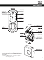
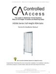
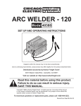
Main Features
Outside
Low Battery
Indicator
Integrated
Key Card Reader
Inside*
Emergency 9V
Power Supply
Terminal
Lock functions explained in Product Definitions,
refer page 7.
* - Note: The Battery Pack assembly is only for
internal applications.
3
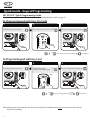
Quick Guide - Keypad Programming
001TOUCH™ Quick Programming Guide
Note: This quick guide is for EZ Mode only, for Advanced Mode please refer to page 11.
To Program Keypad with User Pin Code
3
1
2
Press Registration Button.
Enter desired user PIN code
U
U
Re-press Registration Button.
User Pin Code Registration
Complete
To Program Keypad with Key Card
1
Press Registration Button.
3
2
Present Key Card(s)
wait for confirmation beep.
U
Re-press Registration Button.
BEEP
U
Key Card Registration
Repeat
if required
Complete
Note: Always ensure you test the User PIN code and Key Card with the door open to ensure the lock code or
Key Card is working.
4
Quick Guide - Keypad Operation
001TOUCH™ Quick User Guide
Note: This quick guide is for EZ Mode only, for Advanced Mode please refer to page 11.
To Open Door with User PIN Code
1
Touch lock with palm
of hand or fingers
to activate.
2
3
4
Enter user PIN Code.
Complete your verification
with a palm - touch or by
pressing key.
Unlock, rotate knob.
To Open Door with Key Card
Contact Key Card.
Unlock, rotate knob.
Quick Notes
Programming the card key will not effect the user PIN code.
Programming the user PIN code will not effect the card key.
If you want to delete the user PIN code simply program your new user PIN code and the old code will be deleted
automatically.
In order to remove one or more key cards programmed to the lock, simply reprogram all the key card/s present.
The key card/s not present during this will no longer be valid.
You are able to program a visitor code into the lock that may last 3 to 366 hours, please refer to page 10 for more
details.
It is important to note as a backup that you always need to enrol your user PIN code and key card.
Batteries – Its important to use four quality Alkaline Batteries and all four batteries are replaced at the same time.
Cryptic code function - Prevent others from identifying your pin code during access, the cryptic code function
confuses the onlooker but at the same time allows you to still gain entry. You are able to enter any random
amounts of digits before you enter your actual code, followed by your real pin code. e.g. if you code is 1234
enter 2345672910171234. You are also able to enter you pin first followed by any random numbers.
e.g. 123427364830280
5
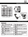
Keypad Functions
Smart Pad
Low Battery Warning
Wrong Code Entry Limit Warning
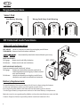
001 Internal Lock Functions
Internal Lock Operation
KEY INSIDE: Locks or unlocks turn knob by turning key one full turn.
TURN KNOB: Retracts latch bolt when unlocked.
: Automatically unlocks the internal knob upon entry.
BOLT HOLD BACK :
To Engage:
Rotate turn knob fully clockwise.
To Release: Rotate turn knob anti-clockwise.
001 LOCK
BOLT HOLD BACK WITH KEY :
Prevents unauthorised "hold back" release.
To Engage:
Rotate turn knob fully clockwise and lock in
rotated position by turning key in knob one full
turn anti-clockwise.
To Release:
Unlock turn knob by turning key one full turn
clockwise and rotate turn knob anti-clockwise.
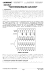
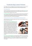
Battery Replacement
To install batteries, first remove Battery Pack Cover by depressing the buttons
on the top and bottom of the case, then gently remove cover.
Insert 4 good quality alkaline AA batteries into the Battery pack as shown.
2 in the upper battery compartment and two in the lower battery compartment.
Batteries must be new good quality alkaline and not be mixed between new and old.
Caution: Dispose of them responsibly and do not throw batteries in fire.
6
Product Definitions
EZ Mode: (Factory default) In this mode you are able to enrol one User PIN code as well as 20 additional key cards.
This mode is normally used for a residential homes.
Advanced Mode: This mode can be selected at point of installation. Advanced mode enables you to have a master
code, the master code is able to add 20 different users with a PIN code and 20 Users with a Key Card (40 users in
total). Only the master can add or delete users using their PIN. This is normally used to control access or where
users may be removed when required.
User PIN Code: Is a personalised identification number that consist of 4-12 digits
Master Code: Is a personalised identification number that consist of 6 digits and is only required when in
advanced mode. The Master code has the ability to add and delete users.
Key Card: Is a unique card that can be used like a key. The Key Card can be reused as many times as you want.
The Key Card can be used as a backup if you forget your pin code or used instead of your pin. To use the Key Card
present it near the centre of the Touch screen for 1-2 seconds, the Key Card does not have to touch the keypad and
can be 2cm away from the lock.
Confirm button: The
button is used to complete verification after user PIN code is entered.
Wrong Code/card Entry Limit: After 5 unsuccessful attempts at entering a valid user PIN code or Valid Key Card the
unit will shut down for 3 minutes and not allow operation during this time. The lock will display how many minutes
are left in this lock down mode, as per page 6.
Registration Button: Located on the battery pack mounting Plate, the Registration button is used for changing the
user PIN code or enrolling new Key Cards (Only in EZ mode).
Low Battery: When the battery power is low, the low battery icon will appear. Further more the lock will beep
5 times when unlocked. If battery power is completely lost, the emergency power supply can be used.
Low Battery check: The battery level can be checked without removing the batteries. With a simple sequence of
buttons you can check your battery level (Between 100%-30%). Refer to page 10 For more details.
Emergency Power Supply: 9V battery connections are located under the front of the outside escutcheon. In the
event that the four AA alkaline batteries are completely discharged, a 9V battery can be used to supply power to the
lock. While connecting the 9V battery, the lock can be operated as normal, thus granting access so the four AA
alkaline batteries can be replaced.
Soft reset: Located in between the Emergency 9V Power socket this small hidden button is used to refresh the
internal software, all your settings will remain i.e. user Pin code and Key cards. This can be pushed with a small
object i.e. pen. Once pressed you will hear confirmation. This is only ever used in the event your lock malfunctions.
Passage Mode: Enabling Passage mode allows continuous entry for non-restricted traffic. Passage mode is enabled
or disabled through feature programming. Refer to page 10 For more details.
Visitor PIN: The Visitor PIN is a temporary code that expires after a period between 3-336 hours. This is ideal when a
plumber or an electrician requires access to your house for a few hours or when your neighbour is looking after
your home for up to 2 weeks. All you have to do is program the PIN and the duration . Time may vary up to 10%,
refer to page 10 for more details.
Volume adjustment: You have 3 levels of volume adjustment, 1 – Silent 2 – Medium 3 –Loud (3-Factory default)
Silent Mode: Enabling Silent mode shuts off the code confirmation tone playback for use in quiet areas.
Status LED: Located on inside escutcheon indicated red when powered up.
7
EZ Mode Functions
Factory Defaults
User PIN Code
To set EZ Mode slide
switch to EZ followed by
the soft rest
*
*
*
EZ mode allows for a single User PIN Code to be assigned.
Up to 20 Key Cards can be programmed into the 001 Touch in this mode.
With the use of the User PIN Code a number of basic functions outline on page 10 can be accessed.
A User PIN Code between 4 to 12 digits can be entered.
For programming new User PIN Code in EZ mode refer to the next page.
* - These values cannot be changed.
Programming Features
Menu & Icons
U
V
~
U
Registration User PIN code or
Key Cards in EZ Mode
8
Enter User PIN code. Can be 4 to 12 digits
in length. Factory default: 1234567890
Enter user Key Card(s). Up to 20 cards.
Keypad Programming - EZ Mode
To Program Keypad with Pin code
3
1
2
Press Registration Button.
Enter desired user PIN code
After removing the battery cover
press the Registration button, you
will hear a confirmation tone.
U
Re-press Registration Button.
You now have 20 seconds to enter
your 4-12 digit user PIN code.
U
Re-press the Registration button,
you will hear another confirmation
tone. Now watch the keypad and
your code will briefly appear.
User PIN code Registration
To Program Keypad with Key Card
1
Press Registration Button.
3
2
Present Key Card(s)
wait for confirmation beep.
U
Re-press Registration Button.
BEEP
After removing the battery cover
press the Registration button, you
will hear a confirmation tone.
You now have 20 seconds to present
card to lock, wait for beep and if
you require additional cards
repeat.(up to 20 Cards)
U
Re-press the Registration button,
you will hear another confirmation
tone
Key Card Registration
Repeat
if required
Complete
9
Keypad Functions - EZ Mode
User PIN Code / Key Card registration
U
User PIN Code Registration
U
User Key Card Registration
Complete
Complete
User PIN Code / Key Card Function
1. Touch screen with hand or fingers to activate.
2. Enter 4-12 digit User PIN code followed by the key.
3. Enter digit (
) corresponding to the function to be performed followed by the
4. Now enter desired value/code followed by the key
5. Press the key to complete the process and conclude the programming session.
U
V
Visitor Code Registration
New Visitor Code
Delete Visitor Code
Passage Mode
Volume Setting
Battery Check Mode
Cancel
10
Enable
Complete
Disable
Complete
Silent
Complete
Normal
Complete
High
Complete
1~3 appear through individual lighting
key.
Time Setting(3 ~336 hours)
Complete
(Note: Actual time may vary by up to 10%)
? (3 greater 70%, 2 is between 35 - 70%, 1 less 35%)
Advanced Mode Functions
Factory Defaults
To set Advanced Mode slide
switch to Advanced followed
by the soft reset.
*
*
*
* - These values cannot be changed.
Programming Features
Menu & Icons
M
U
~
Enter User PIN code. Can be 4 to 12 digits
in length. Factory default: 1234567890
V
U
Enter user Key Card(s). Up to 20 cards.
Registration User PIN code or
Key Cards in EZ Mode
11
Keypad Programming - Advanced Mode
Register / Change Master Code
1
2
3
Enter current Master PIN code and
followed by the key
Enter ‘1’ to change the Master code
and followed by the key
Enter the new Master PIN code (6 digits),
followed by the key to complete.
M
M
Master Code Registration
User PIN Code / Key Card Registration
01~20
U
Continue
Complete
21~40
U
Continue
Complete
Advanced Mode allows for up to 20 User PIN Codes and 20 Key Cards to be assigned.
User PIN Codes and Key Cards can only be added or removed once the Master code has been entered.
With the use of the Master Code a number of advanced functions outline on page 13 can be accessed.
A 6 digit Master Code can be entered. (Master code and User PIN Code must be different).
12
Keypad Functions - Advanced Mode
Master and User PIN Code / Key Card registration
M
M
Master Code Registration
U
01~20
User PIN Code / Key Card Registration
Continue
Complete
U
21~40
Continue
Complete
Master Code / Key Card Function
1. Touch screen with hand or fingers to activate.
2. Enter 6 digit Master code followed by the key.
3. Enter digit (
) corresponding to the function to be performed followed by the
4. Now enter desired value/code followed by the key
5. Press the key to complete the process and conclude the programming session.
M
01~40
Delete Code / Card
key.
Continue
Complete
M
Delete All
Visitor Code Registration
6 Digits
V
Complete
New Visitor Code
Delete Visitor Code
Passage Mode
Volume Setting
Battery Check Mode
Enable
Complete
Disable
Complete
Silent
Complete
Normal
Complete
High
Complete
1~3 appear through individual lighting
Time Setting(3 ~336 hours)
Complete
(Note: Actual time may vary by up to 10%)
? (3 greater 70%, 2 is between 35 - 70%, 1 less 35%)
Cancel
13
Emergency Power Supply
9V battery connections are located under the front of the outside escutcheon.
In the case that the 4 AA alkaline batteries are completely discharged, a 9V battery can
be used to supply power to the lock. While connecting the 9V battery, the lock can be
operated as normal, thus granting access so the 4 AA alkaline batteries can be
replaced. Discharged batteries should be replaced right away.
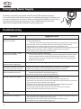
Troubleshooting
Symptom
Suggested Action
Lock does not respond – door is
open and accessible.
• The touchscreen will become active when pressed with the palm or fingers in at least
3 areas simultaneously.
- Use a larger area of the palm or fingers and verify contact with at least 3 areas (page 5).
• If touchscreen numbers are visible, check to see if they respond when pressed.
• Check batteries are installed and oriented correctly in the battery case.
• Check batteries are in good condition(page 10); replace batteries if discharged (page 6).
• Check to see if touchscreen cable is properly connected and not pinched.
• Push Soft Reset until confirmation sound is heard.
Lock does not respond – door is
locked and inaccessible.
• Batteries may be completely discharged.
- Connect a 9-volt battery to the emergency power supply terminal which is located
on the outside escutcheon, under the knob. With the 9-volt battery connected,
palm the touchscreen, enter user PIN code, and palm touchscreen again (page 5).
Replace batteries (page 6).
The unit is on for a while, and then
shows no reaction. Lights dim.
• The batteries do not have enough power. Replace the batteries.
Unit chimes to indicate code acceptance, but the door will not open.
• Check to see if there is another locking device on the door (i.e. deadbolt).
• Check the door gaps for any foreign objects between door and frame.
Unit operates to allow access, but
will not automatically re-lock.
• Check to see if Passage Mode is enabled.
- Disable Passage Mode to lock the door (page 10).
• If low battery indicator is lit (page 6), change batteries.
User PIN codes will not register.
• User PIN codes must consist of 4 to 12 digits to register.
• In Advanced mode the same PIN code cannot be used for multiple users.
• In EZ Mode, User PIN codes must be entered within 20 seconds (while the touchscreen
is active) or the process will have to be restarted.
• In EZ Mode, the user PIN code can only be registered using the Registration Button.
• The star (*) can not be used as part of the user PIN code.
• In Advanced mode the Master code must consist of a minimum of 6 digits.
• Master Code and User PIN Code cannot be the same.
The unit operates, but it makes
no sound.
• Check to see if Silent Mode is enabled (page 10 & 13).
The unit shows “Low Battery”
• This is the indication alerting that it is time to replace the batteries. Replace all four (4)
batteries with new AA Alkaline batteries (page 6).
• Check batteries are installed and oriented correctly in the battery case.
• Check batteries are in good condition (page 10).
14
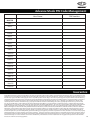
Advance Mode PIN Code Management
User Name
PIN Number
MASTER
User 1
User 2
User 3
User 4
User 5
User 6
User 7
User 8
User 9
User 10
User 11
User 12
User 13
User 14
User 15
User 16
User 17
User 18
User 19
User 20
Guarantee
ASSA ABLOY Australia Pty Limited ("ASSA ABLOY") warrants its Lockwood products against defects in workmanship and materials, subject to the limitations and
exclusions set out in this Warranty. If, within the normal working life of a product, it is found to be defective, and none of the limitations and exclusions set out in
this Warranty apply, ASSA ABLOY will supply the same or equivalent product free of charge. This is the only remedy granted by ASSA ABLOY under this Warranty.
Limitations: All electrical and electronic components used in ASSA ABLOY's Lockwood range of products (excluding batteries) are guaranteed for a period of 12
months from the date of proof of purchase, unless stated otherwise. Exclusions: This Warranty does not cover: 1. Damage to or malfunction or failure of the
Lockwood product caused or contributed to by: (a) improper installation or failure to follow fitting instructions; (b) improper maintenance; c) fair wear and
tear; (d) any modification or repair which has not been authorized by ASSA ABLOY; (e) use of substitute or replacement parts or cylinders other than genuine
ASSA ABLOY parts or cylinders; or (f) use of batteries other than those specified by ASSA ABLOY. 2. The cost of: (a) removal and/or replacement of the Lockwood
product; (b) freight and/or travelling time; c) replacement batteries; or (d) any modification or repairs to a Lockwood product, unless authorised by ASSA
ABLOY. 3. Damage to or deterioration of the plated finishes Florentine Bronze, Architectural Bronze, Polished Brass, Gold and Satin Brass, which are classified as
soft finishes, and are subject to deterioration under some environmental conditions. 4. Damage caused by corrosion when the Lockwood product is used in a
corrosive environment. 5. Personal injury, property damage or economic loss, however caused. Symmetry® 5 Year Finish Warranty: ASSA ABLOY Australia Pty
Limited will replace five-year branded Symmetry product if within five years from the proven date of purchase it tarnishes, discolours or corrodes when properly
installed and subject to no more than fair wear and tear. Symmetry® Everbrass® Warranty: Everbrass product is coated both on the exterior and interior surfaces
with a lifetime anti-tarnish finish. ASSA ABLOY Australia Pty Limited will replace Everbrass branded product if it corrodes, tarnishes or discolours when properly
installed and subject to no more than fair wear and tear. This Warranty is in addition to and not in substitution for any rights of the purchaser under the Trade
Practices Act and state or territory legislation.
15