1
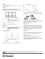
(AUS/NZ)
Ritz Stove
Club Stove
Installation and Operating Instructions
Model: RIT20
Model: CLB20
510
08/19279/1
340
597
510
Issue 1
340
597
Ritz Stove
Club Stove
Fig. 1
IMPORTANT : THESE INSTRUCTIONS SHOULD BE READ CAREFULLY AND RETAINED FOR FUTURE REFERENCE
General
Important Safety Advice:
When using electrical appliances, basic precautions
should be followed to reduce the risk of fire, electric
shock, and injury to persons, including the following :
•
If the appliance is damaged, check immediately
with the supplier before installation and operation.
•
Do not use this heater in the immediate
surroundings of a bath, shower or swimming pool.
•
Do not use outdoors.
•
This heater must not be located immediately below
a fixed socket outlet or connection box.
•
Do not cover or obstruct in any way the heat outlet
grille located at the bottom of the heater.
Overheating will result if the heater is accidentally
covered.
•
Ensure that furniture, curtains or other
combustible materials are positioned no closer
than 1 metre from the heater.
•
In the event of a fault unplug the heater.
•
Unplug the heater when not required for long
periods.
•
Keep supply cord away from the front of the
heater.
•
Although this heater complies with safety
standards, we do not recommend its use on deep
pile carpets or on long hair type of rugs.
•
The appliance is not intended for use by young
children or infirm persons without supervision.
•
Young children or infirm persons should be
supervised to ensure that they do not play with the
appliance.
•
The appliance must be positioned so that the plug
is accessible.
•
If the supply cord is damaged it must be replaced
by the manufacturer or service agent or similarly
qualified person in order to avoid a hazard.
Unpack the heater carefully and retain the packaging for possible
future use, in the event of moving or returning the fire to your
supplier.
This model is designed to be free standing and is normally
positioned against a wall.
A choice of 1kW or 2kW heat output is provided by the fan heater,
which is located at the bottom of the unit.
Before connecting the heater check that the supply voltage is the
same as that stated on the heater.
Please note: Used in an environment where background noise
is very low, it may be possible to hear a sound which is related
to the operation of the flame effect. This is normal and should
not be a cause for concern.
Electrical
WARNING: THIS APPLIANCE MUST BE EARTHED.
This fire is suitable for operation on an AC~ electricity supply having
the same voltage as that shown on its rating label.
Before switching on, please read the safety warnings and operating
instructions.
Operation
The unique flame effect may be enjoyed whether or not the heating
elements are in operation.
Controls
The heater controls are located behind the door of the heater.
Three switches provide a choice of heat settings. A switch is in the
ON position when the side with the markings on (i.e. I , I , or II ) is
pushed in.
Fig. 4
To gain access to the lamps, the four screws which secure the back
panel, must be removed. Remove and slide out panel as indicated
on Fig. 4
Fig. 2
Switch 1 ( I )
Controls the electricity supply to the heater and
flame effect.
Note: This switch must be in the ON
( I ) position for heater to operate with or without
heat.
Switch 2 ( I )
Provides 1kW heat output
Switch 3 ( II )
Provides 2kW output with switch 2
Maintenance
WARNING –
BEFORE UNDERTAKING ANY MAINTENANCE
OR CLEANING REMOVE PLUG OR
DISCONNECT FROM THE ELECTRICITY
SUPPLY.
Fig. 5
Remove the defective lamp by unscrewing it as shown - see Fig. 5.
Replace with a 60W E14 SES Clear Candle lamp.
Take care not to over-tighten the lamp. Refit the back panel and
secure with the four screws.
Safety cut-out
An automatic cut-out will switch off the heater if for any reason it
overheats. This could occur for instance, if the air inlet or outlet were
restricted in any way. If the cut-out operates, the heater will switch
off. The heater will switch on once the obstruction has been
removed and the heater has cooled. If the cut-out continues to
operate intermittently, the heater should be switched off and
Customer Services contacted.
Cleaning
Lamp Replacement
For general cleaning use a soft clean duster – never use abrasive
cleaners. The plastic viewing screen should be cleaned carefully
with a soft cloth. DO NOT use proprietary glass cleaners.
After Sales Service
Please see the separate Warranty leaflet for details of your
Warrantee & after sales service including contact details.
Should you require after sales service, please get in touch with the
supplier through whom you purchased the appliance, or the contact
number on your Warranty leaflet.
Fig. 3
Two lamps are located behind the back panel as indicated in Fig.3.
The product complies with the Australian/New Zealand Safety Standards AS/NZ S 335.2.30:1997 and 2002 Part 1 also the European Standard ElectromagneticCompatibility (EMC)
EN 55 014-1:1993, EN 61000-3-2:1995, EN 61000-3-3:1995, EN 55 014-2:1997 which cover the essential requirements of EEC Directive 89/336/EEC.
Specification subject to change without prior notice.