1
System
Operating Manual
FUJITSU Workstation
CELSIUS M740
CELSIUS M740power
Thank you for buying an innovative product from Fujitsu.
Latest information about our products, useful tips, updates etc. is available
on our website: "http://www.fujitsu.com/fts/"
You can find driver updates at: "http://support.ts.fujitsu.com/download"
Should you have any technical questions, please contact:
our Hotline/Service Desk (see Service Desk list or from the Internet at:
"http://support.ts.fujitsu.com/contact/servicedesk")
• Your sales partner
• Your sales office
We hope you enjoy using your new Fujitsu system!
•
Published by / Contact address in the EU
Fujitsu Technology Solutions GmbH
Mies-van-der-Rohe-Straße 8
80807 Munich, Germany
"http://www.fujitsu.com/fts/"
Copyright
© Fujitsu Technology Solutions GmbH 2014. All rights reserved.
Publication Date
11/2014
Order No.: A26361-K1447-Z320-1-7619, edition 2
FUJITSU Workstation
CELSIUS M740
CELSIUS M740power
Operating Manual
Your CELSIUS...
5
Ports and operating elements
7
Important notes
9
Getting started
14
Operation
21
Troubleshooting and tips
28
System expansions
31
Technical data
74
Index
75
Remarks
Information on the product description meets the design specifications of Fujitsu and
is provided for comparison purposes. Several factors may cause the actual results to
differ. Technical data is subject to change without prior notification. Fujitsu rejects any
responsibility with regard to technical or editorial mistakes or omissions.
Trademarks
Fujitsu, the Fujitsu logo and CELSIUS are registered trademarks of Fujitsu Limited or its
subsidiaries in the United States of America and other countries.
PS/2 is a registered trademark of International Business Machines, Inc.
Pentium is a registered trademark of Intel Corporation, USA.
Kensington and MicroSaver are registered trademarks of ACCO Brands.
Microsoft and Windows are trademarks or registered trademarks of the Microsoft
Corporation in the United States and/or other countries.
All other trademarks specified here are the property of their respective owners.
Copyright
No part of this publication may be copied, reproduced or translated without
the prior written consent of Fujitsu.
No part of this publication may be saved or transferred by any electronic means
without the written approval of Fujitsu.
Contents
Contents
Your CELSIUS... . . . . . . . . . . . . . . . . . . . . . . . . . . . . . . . . . . . . . . . . . . . . . . . . . . . . . . . . . . . . . . . . . . . . . . .
Validity of the Reference Manual . . . . . . . . . . . . . . . . . . . . . . . . . . . . . . . . . . . . . . . . . . . . . . . . . . . . . . . . .
Notational conventions . . . . . . . . . . . . . . . . . . . . . . . . . . . . . . . . . . . . . . . . . . . . . . . . . . . . . . . . . . . . . . . . . .
5
5
6
Ports and operating elements . . . . . . . . . . . . . . . . . . . . . . . . . . . . . . . . . . . . . . . . . . . . . . . . . . . . . . . . .
Front . . . . . . . . . . . . . . . . . . . . . . . . . . . . . . . . . . . . . . . . . . . . . . . . . . . . . . . . . . . . . . . . . . . . . . . . . . . . . . . . . . .
Rear . . . . . . . . . . . . . . . . . . . . . . . . . . . . . . . . . . . . . . . . . . . . . . . . . . . . . . . . . . . . . . . . . . . . . . . . . . . . . . . . . . .
7
7
8
Important notes . . . . . . . . . . . . . . . . . . . . . . . . . . . . . . . . . . . . . . . . . . . . . . . . . . . . . . . . . . . . . . . . . . . . . . . .
Safety information . . . . . . . . . . . . . . . . . . . . . . . . . . . . . . . . . . . . . . . . . . . . . . . . . . . . . . . . . . . . . . . . . . . . . . .
Transporting the device . . . . . . . . . . . . . . . . . . . . . . . . . . . . . . . . . . . . . . . . . . . . . . . . . . . . . . . . . . . . . . . . . .
Cleaning the device . . . . . . . . . . . . . . . . . . . . . . . . . . . . . . . . . . . . . . . . . . . . . . . . . . . . . . . . . . . . . . . . . . . . .
Energy saving, disposal and recycling . . . . . . . . . . . . . . . . . . . . . . . . . . . . . . . . . . . . . . . . . . . . . . . . . . . .
CE marking . . . . . . . . . . . . . . . . . . . . . . . . . . . . . . . . . . . . . . . . . . . . . . . . . . . . . . . . . . . . . . . . . . . . . . . . . . . .
EMC standard EN 55022:2010 (Information technology equipment - Radio disturbance
characteristics - Limits and methods of measurement) . . . . . . . . . . . . . . . . . . . . . . . . . . . . . . . . . . . . .
FCC Compliance Statement . . . . . . . . . . . . . . . . . . . . . . . . . . . . . . . . . . . . . . . . . . . . . . . . . . . . . . . . . . . . .
FCC Class A Compliance Statement . . . . . . . . . . . . . . . . . . . . . . . . . . . . . . . . . . . . . . . . . . . . . . . . . .
FCC Class B Compliance Statement . . . . . . . . . . . . . . . . . . . . . . . . . . . . . . . . . . . . . . . . . . . . . . . . . .
FCC Radiation Exposure Statement . . . . . . . . . . . . . . . . . . . . . . . . . . . . . . . . . . . . . . . . . . . . . . . . . .
9
9
9
10
10
11
Getting started . . . . . . . . . . . . . . . . . . . . . . . . . . . . . . . . . . . . . . . . . . . . . . . . . . . . . . . . . . . . . . . . . . . . . . . . .
Unpacking and checking the delivery . . . . . . . . . . . . . . . . . . . . . . . . . . . . . . . . . . . . . . . . . . . . . . . . . . . . .
Steps for initial setup . . . . . . . . . . . . . . . . . . . . . . . . . . . . . . . . . . . . . . . . . . . . . . . . . . . . . . . . . . . . . . . . . . . .
Setting up the device . . . . . . . . . . . . . . . . . . . . . . . . . . . . . . . . . . . . . . . . . . . . . . . . . . . . . . . . . . . . . . . . . . . .
Connecting the machine to the mains . . . . . . . . . . . . . . . . . . . . . . . . . . . . . . . . . . . . . . . . . . . . . . . . . . . . .
Connecting external devices . . . . . . . . . . . . . . . . . . . . . . . . . . . . . . . . . . . . . . . . . . . . . . . . . . . . . . . . . . . . .
Ports on the device . . . . . . . . . . . . . . . . . . . . . . . . . . . . . . . . . . . . . . . . . . . . . . . . . . . . . . . . . . . . . . . . . .
Connecting a monitor . . . . . . . . . . . . . . . . . . . . . . . . . . . . . . . . . . . . . . . . . . . . . . . . . . . . . . . . . . . . . . . .
Connecting a USB mouse . . . . . . . . . . . . . . . . . . . . . . . . . . . . . . . . . . . . . . . . . . . . . . . . . . . . . . . . . . . .
Connecting a USB keyboard . . . . . . . . . . . . . . . . . . . . . . . . . . . . . . . . . . . . . . . . . . . . . . . . . . . . . . . . .
Connecting external devices to the USB ports . . . . . . . . . . . . . . . . . . . . . . . . . . . . . . . . . . . . . . . . .
Switching on for the first time: installing the software . . . . . . . . . . . . . . . . . . . . . . . . . . . . . . . . . . . . . . .
Switch on the monitor and the machine . . . . . . . . . . . . . . . . . . . . . . . . . . . . . . . . . . . . . . . . . . . . . . .
Installing the software . . . . . . . . . . . . . . . . . . . . . . . . . . . . . . . . . . . . . . . . . . . . . . . . . . . . . . . . . . . . . . .
14
14
14
15
15
16
16
17
18
18
18
19
19
20
Operation . . . . . . . . . . . . . . . . . . . . . . . . . . . . . . . . . . . . . . . . . . . . . . . . . . . . . . . . . . . . . . . . . . . . . . . . . . . . . .
Switch the device on . . . . . . . . . . . . . . . . . . . . . . . . . . . . . . . . . . . . . . . . . . . . . . . . . . . . . . . . . . . . . . . . . . . .
Switching off the device . . . . . . . . . . . . . . . . . . . . . . . . . . . . . . . . . . . . . . . . . . . . . . . . . . . . . . . . . . . . . . . . .
Indicators on the device . . . . . . . . . . . . . . . . . . . . . . . . . . . . . . . . . . . . . . . . . . . . . . . . . . . . . . . . . . . . . . . . .
Keyboard . . . . . . . . . . . . . . . . . . . . . . . . . . . . . . . . . . . . . . . . . . . . . . . . . . . . . . . . . . . . . . . . . . . . . . . . . . . . . . .
Important keys and keyboard shortcuts . . . . . . . . . . . . . . . . . . . . . . . . . . . . . . . . . . . . . . . . . . . . . . . .
Settings in BIOS Setup . . . . . . . . . . . . . . . . . . . . . . . . . . . . . . . . . . . . . . . . . . . . . . . . . . . . . . . . . . . . . . . . . .
Property and data protection . . . . . . . . . . . . . . . . . . . . . . . . . . . . . . . . . . . . . . . . . . . . . . . . . . . . . . . . . . . . .
Anti-theft protection and lead-sealing . . . . . . . . . . . . . . . . . . . . . . . . . . . . . . . . . . . . . . . . . . . . . . . . . .
Mechanical casing lock (optional) . . . . . . . . . . . . . . . . . . . . . . . . . . . . . . . . . . . . . . . . . . . . . . . . . . . . .
BIOS setup security functions . . . . . . . . . . . . . . . . . . . . . . . . . . . . . . . . . . . . . . . . . . . . . . . . . . . . . . . .
Access authorisation via SmartCard . . . . . . . . . . . . . . . . . . . . . . . . . . . . . . . . . . . . . . . . . . . . . . . . . .
Operating the SmartCard reader (optional) . . . . . . . . . . . . . . . . . . . . . . . . . . . . . . . . . . . . . . . . . . . .
21
21
21
22
23
23
24
25
25
26
27
27
27
Troubleshooting and tips . . . . . . . . . . . . . . . . . . . . . . . . . . . . . . . . . . . . . . . . . . . . . . . . . . . . . . . . . . . . . .
Help if problems occur . . . . . . . . . . . . . . . . . . . . . . . . . . . . . . . . . . . . . . . . . . . . . . . . . . . . . . . . . . . . . . . . . . .
28
28
Fujitsu
11
12
12
13
13
3
Contents
Troubleshooting . . . . . . . . . . . . . . . . . . . . . . . . . . . . . . . . . . . . . . . . . . . . . . . . . . . . . . . . . . . . . . . . . . . . . . . . .
Power-on indicator remains unlit after you have switched on your device . . . . . . . . . . . . . . . . .
The device cannot be switched off with the ON/OFF switch . . . . . . . . . . . . . . . . . . . . . . . . . . . . .
Monitor remains blank . . . . . . . . . . . . . . . . . . . . . . . . . . . . . . . . . . . . . . . . . . . . . . . . . . . . . . . . . . . . . . .
Time and/or date is not correct . . . . . . . . . . . . . . . . . . . . . . . . . . . . . . . . . . . . . . . . . . . . . . . . . . . . . . .
Error messages on the screen . . . . . . . . . . . . . . . . . . . . . . . . . . . . . . . . . . . . . . . . . . . . . . . . . . . . . . . .
Installing new software . . . . . . . . . . . . . . . . . . . . . . . . . . . . . . . . . . . . . . . . . . . . . . . . . . . . . . . . . . . . . . . . . .
Restoring the hard disk contents . . . . . . . . . . . . . . . . . . . . . . . . . . . . . . . . . . . . . . . . . . . . . . . . . . . . . . . . .
Tips . . . . . . . . . . . . . . . . . . . . . . . . . . . . . . . . . . . . . . . . . . . . . . . . . . . . . . . . . . . . . . . . . . . . . . . . . . . . . . . . . . . .
28
28
29
29
30
30
30
30
30
System expansions . . . . . . . . . . . . . . . . . . . . . . . . . . . . . . . . . . . . . . . . . . . . . . . . . . . . . . . . . . . . . . . . . . . .
Information about boards . . . . . . . . . . . . . . . . . . . . . . . . . . . . . . . . . . . . . . . . . . . . . . . . . . . . . . . . . . . . . . . .
Opening the casing . . . . . . . . . . . . . . . . . . . . . . . . . . . . . . . . . . . . . . . . . . . . . . . . . . . . . . . . . . . . . . . . . . . . .
Closing the casing . . . . . . . . . . . . . . . . . . . . . . . . . . . . . . . . . . . . . . . . . . . . . . . . . . . . . . . . . . . . . . . . . . . . . .
Overview of drive bays and drives in your device . . . . . . . . . . . . . . . . . . . . . . . . . . . . . . . . . . . . . . . . . .
Installing and removing the accessible 51/4 inch drive (Ultra Slim, top drive bay) . . . . . . . . . . . . . .
Installing an accessible drive . . . . . . . . . . . . . . . . . . . . . . . . . . . . . . . . . . . . . . . . . . . . . . . . . . . . . . . . .
Removing an accessible drive . . . . . . . . . . . . . . . . . . . . . . . . . . . . . . . . . . . . . . . . . . . . . . . . . . . . . . . .
Installing and removing the accessible 51/4 inch drive (standard size, bottom drive bay) . . . . . . .
Fitting the drive cover for the 5 1/4 inch drive . . . . . . . . . . . . . . . . . . . . . . . . . . . . . . . . . . . . . . . . . . .
Installing an accessible drive . . . . . . . . . . . . . . . . . . . . . . . . . . . . . . . . . . . . . . . . . . . . . . . . . . . . . . . . .
Removing an accessible drive . . . . . . . . . . . . . . . . . . . . . . . . . . . . . . . . . . . . . . . . . . . . . . . . . . . . . . . .
Installing/removing a 3½" reader in a 3½" bay (optional, SmartCard or MultiCard) . . . . . . . . . . . .
Removing the module holder . . . . . . . . . . . . . . . . . . . . . . . . . . . . . . . . . . . . . . . . . . . . . . . . . . . . . . . . .
Screwing the reader onto the module holder . . . . . . . . . . . . . . . . . . . . . . . . . . . . . . . . . . . . . . . . . . .
Installing a module holder with reader . . . . . . . . . . . . . . . . . . . . . . . . . . . . . . . . . . . . . . . . . . . . . . . . .
Removing a module holder with reader . . . . . . . . . . . . . . . . . . . . . . . . . . . . . . . . . . . . . . . . . . . . . . . .
Removing the reader from the module holder . . . . . . . . . . . . . . . . . . . . . . . . . . . . . . . . . . . . . . . . . .
Installing the hard disk drive . . . . . . . . . . . . . . . . . . . . . . . . . . . . . . . . . . . . . . . . . . . . . . . . . . . . . . . . . . . . .
Mounting or replugging the cold plug master cable . . . . . . . . . . . . . . . . . . . . . . . . . . . . . . . . . . . . .
Installing a new assembly kit (for expansion from 4 to max. 8 drives) . . . . . . . . . . . . . . . . . . . .
Installing hard disks . . . . . . . . . . . . . . . . . . . . . . . . . . . . . . . . . . . . . . . . . . . . . . . . . . . . . . . . . . . . . . . . .
Removing a hard disk . . . . . . . . . . . . . . . . . . . . . . . . . . . . . . . . . . . . . . . . . . . . . . . . . . . . . . . . . . . . . . .
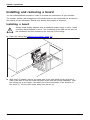
Installing and removing a board . . . . . . . . . . . . . . . . . . . . . . . . . . . . . . . . . . . . . . . . . . . . . . . . . . . . . . . . . .
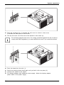
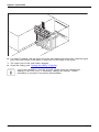
Installing a board . . . . . . . . . . . . . . . . . . . . . . . . . . . . . . . . . . . . . . . . . . . . . . . . . . . . . . . . . . . . . . . . . . . .
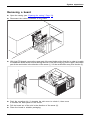
Removing a board . . . . . . . . . . . . . . . . . . . . . . . . . . . . . . . . . . . . . . . . . . . . . . . . . . . . . . . . . . . . . . . . . . .
Connecting display adapters with additional power supply . . . . . . . . . . . . . . . . . . . . . . . . . . . . . . . . . .
Upgrading main memory . . . . . . . . . . . . . . . . . . . . . . . . . . . . . . . . . . . . . . . . . . . . . . . . . . . . . . . . . . . . . . . .
Removing and installing the hard disk fan . . . . . . . . . . . . . . . . . . . . . . . . . . . . . . . . . . . . . . . . . . . . .
Removing and installing the rear fan . . . . . . . . . . . . . . . . . . . . . . . . . . . . . . . . . . . . . . . . . . . . . . . . . .
Replacing the processor . . . . . . . . . . . . . . . . . . . . . . . . . . . . . . . . . . . . . . . . . . . . . . . . . . . . . . . . . . . . . . . . .
Installing and removing heat sinks . . . . . . . . . . . . . . . . . . . . . . . . . . . . . . . . . . . . . . . . . . . . . . . . . . . . . . . .
Removing the heat sink . . . . . . . . . . . . . . . . . . . . . . . . . . . . . . . . . . . . . . . . . . . . . . . . . . . . . . . . . . . . . .
Installing the heat sink . . . . . . . . . . . . . . . . . . . . . . . . . . . . . . . . . . . . . . . . . . . . . . . . . . . . . . . . . . . . . . .
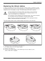
Replacing the lithium battery . . . . . . . . . . . . . . . . . . . . . . . . . . . . . . . . . . . . . . . . . . . . . . . . . . . . . . . . . . . . .
31
32
33
34
34
35
35
37
39
39
40
41
42
43
43
44
45
46
46
48
51
54
57
60
60
63
66
66
67
70
71
71
71
72
73
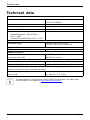
Technical data . . . . . . . . . . . . . . . . . . . . . . . . . . . . . . . . . . . . . . . . . . . . . . . . . . . . . . . . . . . . . . . . . . . . . . . . .
74
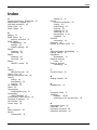
Index . . . . . . . . . . . . . . . . . . . . . . . . . . . . . . . . . . . . . . . . . . . . . . . . . . . . . . . . . . . . . . . . . . . . . . . . . . . . . . . . . .
75
4
Fujitsu
Your CELSIUS...
Your CELSIUS...
Overview
... is available with various configuration levels which differ in terms of hardware and software
equipment. You can install accessible drives (e.g. DVD drives) and other modules.
This manual tells you how to start using your device and how to operate it in daily use.
This manual applies for all configuration levels. Depending on the chosen configuration
level, some of the hardware components described may not be available on your PC.
Please also read the notes about your operating system.
Depending on the configuration selected, the operating system is preinstalled
on your hard disk (e.g. Windows 8).
Further information on this device is also provided:
•
•
•
•
•
•
•
in
in
in
in
in
in
in
the "Quick Start Guide" poster
the "Safety/regulations" manual
the "Warranty" manual
the operating manual for the monitor
the manual for the mainboard
the documentation for your operating system
the information files (e.g. *.PDF, *.HTML, *.DOC, *.CHM, *.TXT, *.HLP)
Some of the manuals listed can be found in electronic form on the "Drivers & Utilities" DVD.
You can access and view the required information using the Acrobat Reader program,
which is also included on the DVD. If necessary, you can also print out the manuals.
Validity of the Reference Manual
This Reference Manual is valid for the following system:
•
•
FUJITSU Workstation CELSIUS M740
FUJITSU Workstation CELSIUS M740power
Fujitsu
5
Your CELSIUS...
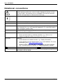
Notational conventions
Pay particular attention to text marked with this symbol. Failure to observe
these warnings could pose a risk to health, damage the device or lead
to loss of data. The warranty will be invalidated if the device becomes
defective through failure to observe these warnings.
Indicates important information for the proper use of the device.
►
Indicates an activity that must be performed
Indicates a result
This font
indicates data entered using the keyboard in a program dialogue or at
the command line, e.g. your password (Name123) or a command used to
start a program (start.exe)
indicates information that is displayed on the screen by a program, e.g.:
Installation is complete.
indicates
"This font"
• terms and texts used in a software interface, e.g.: Click on Save
• names of programs or files, e.g. Windows or setup.exe.
indicates
This font
This font
•
•
Key
This font
6
cross-references to another section, e.g. "Safety information"
cross-references to an external source, e.g. a web address: For more
information, go to "http://www.fujitsu.com/fts"
• Names of CDs, DVDs and titles or designations for other materials,
e.g.: "CD/DVD Drivers & Utilities" or "Safety/Regulations" manual
indicates a key on the keyboard, e.g: F10
indicates terms and texts that are emphasised or highlighted, e.g.: Do
not switch off the device
Fujitsu
Ports and operating elements
Ports and operating elements
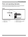
Ports
This chapter presents the individual hardware components of your device. This will provide
you with an overview of the ports and operating elements on the device. Please familiarise
yourself with these components before starting to work with your device.
Front
8
1
2
3
4
5
6
7
1
2
3
4
=
=
=
=
Module bays for 51/4" drives
Module bays for 31/2" drives
ON/OFF switch
Headphone port
Fujitsu
5
6
7
8
=
=
=
=
Microphone jack
USB ports (2 x USB 3.0, 2 x USB 2.0)
Hard disk front panel (removable)
Casing lock (optional)
7
Ports and operating elements
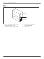
Rear
1
2
3
4
1 = Holes for padlock / lead seal and
device for Security Lock
2 = Alternating voltage socket (AC IN)
8
3 = Ports for external devices
(device-dependent)
4 = Slot covers
Fujitsu
Important notes
Important notes
Notes
Importantnotes
In this chapter you will find information regarding safety which it is essential to
take note of when working with your device.
Safety information
Note
Safetyinformation
Please note the information provided in the "Safety/regulations" manual
and in the following safety notes.
When installing and operating the device, please observe the notes on
environmental conditions in Chapter "Technical data", Page 74 as well as
the instructions in Chapter "Getting started", Page 14.
When setting up the device, make sure there is clearance all around it so that
the casing receives enough ventilation. In order to avoid overheating, do not
cover the ventilation areas of the monitor or the device.
You must only operate the device if the rated voltage used by the
device is set to the local mains voltage.
You must remove the power plug from the power socket so that the
mains voltage is completely disconnected.
Operate the device only with the casing closed.
Replace the lithium battery on the mainboard in accordance with the instructions
in "Replacing the lithium battery", Page 73.
Caution, components in the system can get very hot.
The activities described in these instructions must always be
performed with the greatest care.
Repairs to the device must only be performed by qualified technicians.
Incorrect repairs could put the user at great risk or cause serious damage
to the equipment (electric shock, risk of fire).
Transporting the device
Retransportation
Transportation
Device,
Transport all parts separately in their original packaging or in a packaging which
protects them from knocks and jolts, to the new site.
Do not unpack them until all transportation manoeuvres are completed.
If the device is brought from a cold environment into the room where it will be
used, condensation may occur. To avoid damaging the device, wait until it has
reached room temperature and is absolutely dry before initial startup.
Fujitsu
9
Important notes
Cleaning the device
System unit,see Device
Retransportation
Transportation
Device,
Turn off all power and equipment switches and disconnect the power
plug from the mains outlet.
Do not clean any interior parts yourself, leave this job to a service technician.
Do not use any cleaning agents that contain abrasives or may corrode
plastic (alcohol, thinner or acetone).
Never clean the device with water! Water entering into the device could
present a serious risk to users (e.g. electric shock).
Ensure that no liquid enters the system.
The surface can be cleaned with a dry cloth. If particularly dirty, use a cloth that has been
moistened in mild domestic detergent and then carefully wrung out.
Use disinfectant wipes to clean the keyboard and the mouse.
Energy saving, disposal and recycling
Drivers&
Recycling
Energysaving
Disposal
User
DocumentationDVD
UtilitiesDVD
You can find information on these subjects on the "Drivers & Utilities" DVD or on our
website ("http://www.fujitsu.com/fts/about/fts/environment-care/").
For China: The energy efficiency of this product has been tested in accordance with
GB 28380. The corresponding energy efficiency label can be used.
10
Fujitsu
Important notes
CE marking
Lowvoltagedirective
Electromagneticcompatibility
Notes
CEmarking
The shipped version of this device complies with the requirements of EU directives 2004/108/EC
"Electromagnetic compatibility", 2006/95/EC "Low voltage directive", 2011/65/EC "RoHS directive"
and 2009/125/EC "ecodesign directive".
CE marking for devices with radio component
This equipment complies with the requirements of Directive 1999/5/EC of the European Parliament
and Commission from 9 March, 1999 governing Radio and Telecommunications Equipment
and mutual recognition of conformity.
CE nnnn (!) ; nnnn: For digits and exclamation mark (!), see label on the product.
You can find more information and declarations of conformity on the Internet at:
"http://globalsp.ts.fujitsu.com/sites/certificates".
This equipment can be used in the following countries:
Belgium
Bulgaria
Denmark
Germany
Estonia
Finland
France
Greece
UK
Ireland
Iceland
Italy
Latvia
Liechtenstein
Lithuania
Croatia
Luxembourg
Malta
Netherlands
Norway
Austria
Poland
Portugal
Rumania
Sweden
Switzerland
Slovakia
Slovenia
Turkey
Hungary
Spain
Czech Republic
Cyprus
Contact the corresponding government office in the respective country for current information on
possible operating restrictions. If your country is not included in the list, then please contact
the corresponding supervisory authority as to whether the use of this product is permitted in
your country.
EMC standard EN 55022:2010 (Information technology
equipment - Radio disturbance characteristics Limits and methods of measurement)
CELSIUS systems whose designation ends with "a" or "an", e.g. CELSIUS M740a,
comply with the standard EN 55022:2010 according to class A.
This equipment may cause radio interference in residential areas. In this case,
the operator can be requested to take appropriate measures.
Fujitsu
11
Important notes
FCC Compliance Statement
CELSIUS systems whose designation ends with "a" or "an", e.g. CELSIUS M740a,
comply with the standard FCC part 15 according to class A.
If the device complies with the FCC regulations, the FCC sign can be found on the type rating plate.
FCC Class A Compliance Statement
The following statement applies to the products covered in this manual, unless otherwise specified
herein. The statement for other products will appear in the accompanying documentation.
NOTE:
This equipment has been tested and found to comply with the limits for a Class A digital
device, pursuant to Part 15 of the FCC Rules and meets all requirements of the Canadian
Interference- Causing Equipment Standard ICES-003 for digital apparatus. These limits
are designed to provide reasonable protection against harmful interference in a residential
installation. This equipment generates, uses, and can radiate radio frequency energy and, if
not installed and used in accordance with the instructions, may cause harmful interference to
radio communications. However, there is no guarantee that interference will not occur in a
particular installation. If this equipment does cause harmful interference to radio or television
reception, which can be determined by turning the equipment off and on, the user is encouraged
to try to correct the interference by one or more of the following measures:
•
•
•
Reorient or relocate the receiving antenna.
Increase the separation between equipment and the receiver.
Connect the equipment into an outlet on a circuit different from that to
which the receiver is connected.
• Consult the dealer or an experienced radio/T.V. technician for help.
Fujitsu Technology Solutions GmbH is not responsible for any radio television interference
caused by unauthorized modifications of this equipment or the substitution or attachment
of connecting cables and equipment other than those specified by Fujitsu Technology
Solutions GmbH. The correction of interference caused by such unauthorized modification,
substitution or attachment will be the responsibility of the user.
The use of shielded I/O cables is required when connecting this equipment to any and all optional
peripheral or host devices. Failure to do so may violate FCC and ICES rules.
12
Fujitsu
Important notes
FCC Class B Compliance Statement
DOC (INDUSTRY CANADA) NOTICES
Notice to Users of Radios and Television:
This class B digital apparatus complies with Canadian ICES-003.
The following statement applies to the products covered in this manual, unless otherwise specified
herein. The statement for other products will appear in the accompanying documentation.
NOTE:
This equipment has been tested and found to comply with the limits for a "Class B" digital
device, pursuant to Part 15 of the FCC rules and meets all requirements of the Canadian
Interference-Causing Equipment Standard ICES-003 for digital apparatus. These limits are
designed to provide reasonable protection against harmful interference in a residential installation.
This equipment generates, uses and can radiate radio frequency energy and, if not installed
and used in strict accordance with the instructions, may cause harmful interference to radio
communications. However, there is no guarantee that interference will not occur in a particular
installation. If this equipment does cause harmful interference to radio or television reception,
which can be determined by turning the equipment off and on, the user is encouraged to
try to correct the interference by one or more of the following measures:
•
•
•
Reorient or relocate the receiving antenna.
Increase the separation between equipment and the receiver.
Connect the equipment into an outlet on a circuit different from that to
which the receiver is connected.
• Consult the dealer or an experienced radio/TV technician for help.
Fujitsu is not responsible for any radio or television interference caused by unauthorized
modifications of this equipment or the substitution or attachment of connecting cables and
equipment other than those specified by Fujitsu. The correction of interferences caused by such
unauthorized modification, substitution or attachment will be the responsibility of the user.
The use of shielded I/O cables is required when connecting this equipment to any and all optional
peripheral or host devices. Failure to do so may violate FCC and ICES rules.
FCC Radiation Exposure Statement
This equipment complies with FCC radiation exposure limits set forth for an uncontrolled environment.
The transmitters in this device must not be co-located or operated in conjunction
with any other antenna or transmitter.
To prevent radio interference to the licensed service, this device is intended to be
operated indoors and away from windows to provide maximum shielding. Equipment (or
its transmit antenna) that is installed outdoors is subject to licensing.
Users are not authorized to modify this product. Any modifications invalidate the warranty.
This equipment may not be modified, altered, or changed in any way without signed
written permission from Fujitsu. Unauthorized modification will void the equipment
authorization from the FCC and Industry Canada and the warranty.
Fujitsu
13
Getting started
Getting started
Gettingstarted
Please observe the safety information in the "Important notes", Page 9 chapter.
Unpacking and checking the delivery
It is recommended not to throw away the original packaging material! It may be
required for reshipment at some later date.
Packaging,
Contentsofdelivery
Packaging
►
►
►
►
Unpack all the individual parts.
Check the contents of the package for any visible damage caused during transport.
Check whether the delivery conforms to the details in the delivery note.
Should you discover that the delivery does not correspond to the delivery
note, notify your local sales outlet immediately.
Steps for initial setup
Preparingforuse,
Preparingforfirstuse,overview
Only a few steps are necessary to put your new device into operation for the first time:
• Select a location for device and set up device
• Connect external devices such as mouse, keyboard and monitor
• Check the voltage at the mains outlet and connect the device to an electrical outlet
• Switch the device on
You will learn more about the individual steps in the following sections.
External devices
If you have received other external devices in addition to your own device (e.g.
a printer), do not connect these until after the initial installation. The following
sections describe how to connect these external devices.
Drives and boards
If you have received drives or boards with your device, please do not install
them until after first-time setup. How to install drives and boards is described
in the "System expansions", Page 31 chapter.
14
Fujitsu
Getting started
Setting up the device
Device
Ergonomic
Workstation
When installing your device, please read the recommendations and safety
notes in the "Safety/regulations" manual.
We recommend that you place your device on a surface which is not slippery. In
view of the many different finishes and varnishes used on furniture, it is possible
that the rubber feet will mark the surface they stand on.
Depending on the location of your device, bothersome vibrations and noises may
occur. To prevent this, a distance of at least 10 mm / 0.39" should be maintained
from other devices on casing sides without ventilation surfaces.
In order to avoid overheating, do not cover the ventilation areas
of the monitor or the device.
A minimum distance of 200 mm / 7.87" from the device must be
observed for ventilation areas.
Do not stack several devices on top of each other.
Do not expose the device to extreme ambient conditions (see "Technical data", Page 74,
section "Ambient conditions"). Protect the device against dust, humidity and heat.
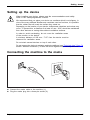
Connecting the machine to the mains
Mainsadapter,
1
2
► Connect the mains cable to the machine (1).
► Plug the mains plug into a three-pin socket (2).
Fujitsu
15
Getting started
Connecting external devices
Read the documentation on the external device before connecting it.
With the exception of USB devices, always remove all power plugs
before connecting external devices!
Do not connect or disconnect cables during a thunderstorm.
Always take hold of the actual plug when disconnecting a cable. Never pull the cable!
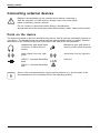
Ports on the device
Device
Externaldevices
Ports
The ports are located on the front and back of the device. Not all ports are necessarily present on
your device. The standard ports are marked with the symbols shown below (or similar). Detailed
information on the location of the ports is provided in the manual for the mainboard.
Headphones, light green (back
of device) or black (front of
device)
Microphone port, pink (back of
device) or black (front of device)
Microphonejack
Headphones
Audio output (Line out), light
green
Audio input (Line in), light blue
Linein
Audioinput
Lineout
Audiooutput
USB 2.0 - Universal Serial Bus,
black
LAN
LAN port
LANport
USB 3.0 - Universal Serial Bus,
blue
UniversalSerialBus
Some of the connected devices require special software (e.g. drivers) (refer to the
documentation for the connected device and operating system).
16
Fujitsu
Getting started
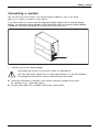
Connecting a monitor
You can use the monitor ports of an optional display adapter in one of the board
slots (1) to connect a monitor to your device.
If you have opted for a device with an integrated display adapter and an optional display
adapter, the integrated display adapter is first deactivated when the optional display adapter
is attached. You need to activate this function first in the BIOS-Setup.
1
1 = Monitor ports of the display adapter
Only attach the monitor to your device when it is switched off.
Use only high-quality signal lines to connect the monitors. For the DVI interface,
we strongly recommend DVI monitor cable S26361-F2391-L400.
► Follow the instructions contained in the monitor manual to prepare the monitor
for operation (e.g. connecting cables).
► Plug the data cable into a suitable monitor port of the device.
Fujitsu
17
Getting started
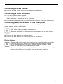
Connecting a USB mouse
► Connect the USB mouse to one of the USB ports on the device.
Connectinga USBmouse
USBport
Connecting a USB keyboard
Use only the keyboard cable supplied.
Connecting
USBport
► Plug the rectangular connector of the keyboard cable into the rectangular socket
on the underside or on the rear of the keyboard.
► Insert the flat rectangular USB plug of the keyboard cable into a USB port of the device.
USBport
Connecting external devices to the USB ports
Devices,
Externaldevices,
USBport,
USBdevices,
You can connect a wide range of external devices to the USB ports (e.g.
printer, scanner, modem or keyboard).
USB devices are hot-pluggable. This means you can connect and disconnect
USB cables while your device is switched on.
Additional information can be found in the documentation for the USB devices.
► Connect the data cable to the external device.
► Connect the data cable to one of the USB ports on your device.
Device drivers
External USB devices which you connect to one of the USB ports don’t usually
need their own drivers because the software required is already included
in the operating system. If the device requires separate software, please
follow the instructions in the manufacturer’s manual.
To ensure the transmission capacity of USB 2.0, the cable from the external USB
device to the USB port of your device must not be longer than 3 m.
18
Fujitsu
Getting started
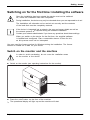
Switching on for the first time: installing the software
Software,
Installing,
Once the installation has been started the device must not be switched
off, unless the installation has been completed.
During installation, the device may only be rebooted when you are requested to do so!
The installation will otherwise not be carried out correctly and the contents
of the hard disk must be completely restored.
If the device is integrated into a network, the user and server details as well as
the network protocol are required during the software installation.
Contact your network administrator if you have any questions about these settings.
When you switch on the device for the first time, the supplied software
is installed and configured. Plan a reasonable amount of time for this,
as this process must not be interrupted.
You may need the licence number for Windows during the installation. The licence
number is located on a label on your device.
Switch on the monitor and the machine
In order to avoid overheating, do not cover the ventilation areas
on the monitor or the device.
► Switch on the monitor (see operating instructions for the monitor).
► Press the on/off button on the front of the machine.
The operational display will light up and the machine will start.
Fujitsu
19
Getting started
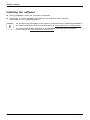
Installing the software
► During installation, follow the on-screen instructions.
► If anything is unclear regarding the data you are asked to input, read the
online Help in your operating system.
Installing,
Software,
You will find more information on the system, as well as drivers, utilities and updates on
the "Drivers & Utilities" DVD and on the Internet at "http://www.fujitsu.com/fts/support".
You can find information and help on the Windows operating system functions
on the Internet at "http://windows.microsoft.com".
20
Fujitsu
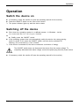
Operation
Operation
Switch the device on
► If necessary, switch the monitor on (see the operating manual for the monitor).
► Press the ON/OFF switch on the front of the device.
The power indicator lights up and the device starts.
Monitor,
Device,
Switching off the device
► Shut down the operating system in a defined manner. In Windows: via the
Start menu and the Turn Off Computer function.
or
► Briefly press the ON/OFF switch.
► If the operating system does not automatically switch the device into energy-saving
mode or switch it off, press the ON/OFF switch until the device switches off.
Warning, this could lead to a loss of data!
If the device is switched off, the device consumes a minimum of energy.
Monitor,
Device,
The ON/OFF switch does not disconnect the device from the mains voltage. To
completely disconnect the mains voltage, remove the power plug from the power socket.
► If necessary, switch the monitor off (see the operating manual for the monitor).
Fujitsu
21
Operation
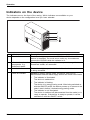
Indicators on the device
The indicators are on the front of the casing. Which indicators are available on your
device depends on the configuration level you have selected.
1
2
3
4
No. indicator
1
Drive indicators
2
3
Indicator for optional
components, e.g.
SmartCard reader
Hard disk indicator
4
Power-on indicator
Description
The indicator lights up when the CD-ROM or DVD drive of the
device is accessed. You must never under any circumstances
remove the CD/DVD while the indicator is lit.
The indicator lights up when optional components, e.g. the
SmartCard reader, are accessed.
The indicator lights up when the hard disk drive in the device
is being accessed.
Caution:In energy saving mode, the device must not be
disconnected from the mains supply as this can cause loss of data.
•
•
•
22
The indicator is illuminated:
The device is switched on.
The indicator is flashing:
The device is in energy-saving mode. After being switched on
with the ON/OFF switch, the device powers up or returns to the
state it was in before it entered energy-saving mode.
The indicator is not illuminated:
The device is switched off (disconnected from the mains) or is
ready to operate. If the device is ready to operate, it can be
switched on with the ON/OFF switch.
Fujitsu
Operation
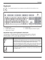
Keyboard
Alphanumeric
Keyboard,
Keyboard
Cursor
Function
Keys,
Numeric
keys
keypad
keys keypad
The illustrated keyboard is an example and may differ from the model you use.
1
2
3
1 = Function keys
2 = On/off switch (optional)
3 = Alphanumeric keypad
4
5
4 = Cursor keys
5 = Numeric keypad (calculator keypad)
Important keys and keyboard shortcuts
Keyboardshortcuts
Keys
The description of the following keys and keyboard shortcuts applies to Microsoft
operating systems. Details of other keys and keyboard shortcuts can be found in
the documentation for the relevant application program.
Key / key combination Description
On/off switch (optional)
Button,
ON/OFFswitch
Depending on the setting in the BIOS Setup, the device can be switched
on or off with this switch. Some operating systems allow you to configure
additional functions of the ON/OFF switch in the Control Panel.
With some keyboards the ON/OFF switch can only be used with an ACPI
(Advanced Configuration and Power Management Interface). Otherwise
the key is inoperative. The mainboard must support this function.
Enter key
Keys,
confirms the highlighted selection. The Enter key is also referred to as
the "Return" key.
Fujitsu
23
Operation
Key / key combination Description
Windows key (device-dependent: variant 1)
Keys,
calls up the Windows Start menu.
Keys,
Menu key (device-dependent: variant 1)
calls up the menu for the marked item (Windows).
Keys
Windows key (device-dependent: variant 2)
Switches between the start screen and the last used application.
Keys
Menu key (device-dependent: variant 2)
Opens the menu for the active application.
Keys,
Shift key
enables upper-case letters and the upper key symbols to be displayed.
Keys,
Alt Gr key (country-dependent)
produces a character shown on the bottom right of a key (e.g. the @
sign on the Q key).
Num Lock key
Keys,
By pressing the Num Lock key you switch between the upper- and
lower-case levels of the calculator keypad.
When the Num Lock indicator is lit the numeric keypad and arithmetic
keys are active.
When the Num Lock indicator is not lit the cursor control functions on the
Numeric keypad are active.
Ctrl key
Keys
Keys,
Ctrl
performs a special operation when pressed in conjunction with another
key. The Ctrl key is also called the "Control" or "Control key".
Windows Security/Task Manager
keyboardshortcuts
Keys
Ctrl+Alt+Del
Ctrl
+
Alt
+
Del
This key combination opens the Windows Security/Task Manager window.
Settings in BIOS Setup
settings,
System
BIOS
Setup,
Setup,
Setup
In BIOS Setup, you can set the system functions and the hardware configuration of the device.
When the PC is delivered, the default entries are valid (see "BIOS Setup" manual or manual for
the mainboard). You can customise these settings to your requirements in the BIOS Setup.
24
Fujitsu
Operation
Property and data protection
Property protection
Securitymeasures
Dataprotection
Software functions and mechanical locking offer a broad range of functions for protecting your
device and your personal data from unauthorised access. You can also combine these functions.
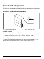
Anti-theft protection and lead-sealing
Chain
KensingtonLock
Anti-theftprotection
Lead-sealing
Casing,
Device,
1
2
1 = Holes for padlock/lead-seal
2 = Device for Security Lock
Anti-theft protection
You can protect your device from theft
•
•
with the holes (1), a padlock and a chain, which you have connected to a fixed object beforehand.
using the Security Lock device (2) and a Kensington MicroSaver. Please
refer to the manual for your Security Lock.
Lead-sealing
To prevent unauthorised persons from opening it, the casing can be lead-sealed. To do this,
feed the sealing chain through the holes (1) and seal the chain with the lead seal.
Fujitsu
25
Operation
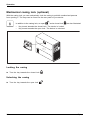
Mechanical casing lock (optional)
Lock lock
Casing
mechanicallock
With the casing lock you can mechanically lock the casing to prohibit unauthorised persons
from opening it. The keys can be found on the rear panel of your device.
In addition to the casing lock, an open
•
•
and a closed lock
are also illustrated.
Key turned towards the closed lock: The device is locked.
Key turned towards the open lock: The device is unlocked.
Locking the casing
► Turn the key towards the closed lock
.
Unlocking the casing
► Turn the key towards the open lock
26
.
Fujitsu
Operation
BIOS setup security functions
BIOS Setup
Securityfunctions
The Security menu in BIOS Setup offers you various options for protecting your
personal data against unauthorized access, e.g.:
• Prevent unauthorized access to BIOS Setup
• Prevent unauthorised system access
• Prevent unauthorised access to the settings of boards with their own BIOS
• Activate virus warnings
• Protect BIOS from overwriting
• Protect the device from being switched on by an external device
You can also combine these functions.
You will find a detailed description of the Security menus and how to assign passwords
in the manual for the mainboard or in the "BIOS Setup" manual.
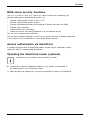
Access authorisation via SmartCard
Accesspermission,SmartCard
Securityfunctions,
In systems equipped with a SmartCard reader, access can be restricted to those
users who have a corresponding SmartCard.
Operating the SmartCard reader (optional)
Operation of this module is not permitted in Taiwan.
► Connect the external SmartCard reader to your system as described in
the instructions for the SmartCard reader.
After the device is switched on, you will be prompted to insert your SmartCard.
SmartCard reader,
Fujitsu
27
Troubleshooting and tips
Troubleshooting and tips
Refer to the safety notes in the "Safety/regulations" manual and in the "Getting
started", Page 14 chapter when connecting or disconnecting cables.
If a fault occurs, try to correct it as described in the following documentation:
•
•
•
•
in
in
in
in
this chapter
the documentation for the connected devices
the help systems of the software used
the documentation for your operating system
Help if problems occur
Should you encounter a problem with your computer that you cannot resolve yourself:
► Note the ID number of your device. The ID number is found on the type rating
plate on the back, the underside or the top of the casing.
► For further clarification of the problem, contact the Service Desk for your country (see the
Service Desk list or visit the Internet at "http://support.ts.fujitsu.com/contact/servicedesk"). When
you do this, please have ready the identity number and serial number of your system.
Troubleshooting
Power-on indicator remains unlit after you have
switched on your device
Cause
The mains voltage supply is faulty.
Internal power supply overloaded.
28
Troubleshooting
► Check whether the power cable is plugged
properly into the device and a grounded
mains outlet.
► Pull the power plug of the device out of the
mains outlet.
► Wait approx. 3 min.
► Plug the power plug into a properly grounded
mains outlet again.
► Switch the device on.
Fujitsu
Troubleshooting and tips
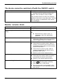
The device cannot be switched off with the ON/OFF switch
Cause
Remedy
System crash
► Keep the on/off switch pressed for at least 4
seconds until the machine switches off.
Caution: This can lead to a loss of data!
This procedure does not allow the operating
system to shut down in an orderly way. The next
time the system is started there may well be
error messages.
Monitor remains blank
Cause
Monitor is switched off.
Power saving has been activated (screen is
blank)
Remedy
► Switch your monitor on.
► Press any key on the keyboard.
or
Brightness control is set to dark
►
Power cable not connected
►
►
►
Monitor cable not connected
Incorrect setting for the monitor
Fujitsu
►
►
►
►
►
►
►
►
► Deactivate the screen saver. If
necessary, enter the appropriate
password.
Adjust the brightness control. For detailed
information, please refer to the operating
manual supplied with your monitor.
Switch off the monitor and the device.
Check that the monitor power cable is
properly connected to the monitor and to
a grounded mains outlet or to the monitor
socket of the device.
Check that the device power cable is
properly plugged into the device and a
grounded mains outlet.
Switch on the monitor and the device.
Switch off the monitor and the device.
Check that the monitor cable is properly
connected to the device and monitor.
Switch on the monitor and the device.
Restart the system.
Press F8 while the system is booting.
Start the system in Safe Mode.
Set up the monitor as described in the
documentation for your operating system
and monitor.
29
Troubleshooting and tips
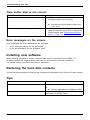
Time and/or date is not correct
Cause
Time and date are incorrect.
Remedy
► Set the correct time and date within the
operating system you are using.
or
The lithium battery is discharged.
► Set the correct time and/or date in the
BIOS Setup.
► If the time and date are repeatedly wrong
when you switch on your device, replace the
lithium battery (see "Replacing the lithium
battery", Page 73).
Error messages on the screen
Error messages and their explanations are provided:
•
•
in the technical manual for the mainboard
in the documentation for the programs used
Installing new software
When installing programs or drivers, important files may be overwritten and modified. To
be able to access the original data in the event of any problems following installation,
you should backup your hard disk prior to installation.
Restoring the hard disk contents
You will find the instructions for restoring the contents of the hard disk in the "Recovery Guide" manual.
Tips
Topic
Lack of system resources
Tip
► Close unnecessary applications.
or
Other manuals
30
► Run the applications in a different order.
Further manuals are provided as PDF files on
the "Drivers & Utilities" DVD.
Fujitsu
System expansions
System expansions
System expansion
Device,
Upgrades,
Servicing
Components
Repairs to the device must only be performed by qualified technicians. Incorrect repairs
may greatly endanger the user (electric shock, fire risk) and will invalidate your warranty.
After consulting the Hotline/Help Desk, you may remove and install the components
described in this manual yourself.
As the device has to be shut down in order to install/deinstall system hardware
components, it is a good idea to print out the relevant sections of this chapter beforehand.
The following illustrations may differ slightly from your device, depending on its configuration level.
If further documentation was delivered with your device, please also read this through carefully.
In addition, before removing or installing system components, please pay attention to the following:
The device must be switched off when installing/removing the system
expansions and may not be in energy-saving mode.
Remove the power plug before opening the device.
Be careful that no wires become trapped when removing or installing components.
When installing components that become very hot, make sure that the maximum
permissible temperature of the components in operation is not exceeded.
An update of the BIOS may be required for a system expansion or hardware
upgrade. Further information can be found in the BIOS help section or if
necessary in the Technical Manual for the mainboard.
Fujitsu
31
System expansions
Information about boards
Take care with the locking mechanisms (catches and centring pins) when you
are replacing boards or components on boards.
Note that some components on the mainboard may be very hot if the device was
in use shortly before the casing was removed.
To prevent damage to the board or the components and conductors on it, please take care when
you insert or remove boards. Make sure expansion boards are inserted straightly.
Never use sharp objects (screwdrivers) for leverage.
Boards with electrostatic sensitive devices (ESD) are identifiable by the label
shown.
When handling boards fitted with ESDs, you must always observe the
following points:
•
•
•
•
32
You must always discharge static build up (e.g. by touching a grounded
object) before working.
The equipment and tools you use must be free of static charges.
Only touch or hold the boards by the edge or, if present, at the areas
marked green (Touch Points).
Never touch pins or conductors on boards fitted with ESDs.
Fujitsu
System expansions
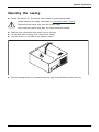
Opening the casing
Device,
Casing,
► Switch the device off. The device must not be in power-saving mode.
Please observe the safety information in "Important notes", Page 9.
Disconnect the mains plug from the mains outlet.
Only insert the power plug after you have closed the casing.
► Remove any connected wires which are in the way.
► On devices with a casing lock: Unlock the casing.
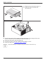
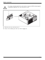
► Lay the device on its side in the manner shown.
2
1
► Pull the locking device (1) and swivel the side part in the direction of the arrow (2).
Fujitsu
33
System expansions
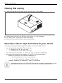
Closing the casing
► Insert the side part in the guide rail on the lower part of the casing.
Device,
Casing,
1
► Swivel the side cover in the direction of the arrow (1) until it engages.
► On devices with a casing lock: Lock the casing.
► Reconnect the cables that you disconnected before.
Overview of drive bays and drives in your device
The casing can accommodate multiple accessible and non-accessible drives:
•
•
•
two drive bays for accessible 51/4 inch drives:
• 1 x Ultra Slim in the top drive bay
• 1 x standard size in the bottom drive bay
two drive bays for accessible 31/2 inch drives (e.g. SmartCard or MultiCard)
Drive bays for multiple non-accessible 21/2" and 31/2" drives (hard disks):
• Maximum equipment with standard installation kit:
○ four 21/2 inch drives or four 31/2 inch drives
○ or: two 21/2 inch drives and two 31/2 inch drives
• Optional installation kit: maximum of eight 21/2 inch drives
"Accessible drives" are e.g. DVD or CD ROM drives, into which a data medium can be
inserted from outside. "Non-accessible drives" are for example hard disk drives.
34
Fujitsu
System expansions
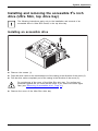
Installing and removing the accessible 51/4 inch
drive (Ultra Slim, top drive bay)
The following instructions apply only to the installation and removal of an
accessible drive in Ultra Slim format, in the top drive bay.
Installing an accessible drive
1
2
3
► Remove the screws (1).
► Push the drive carrier a few centimetres out of the casing in the direction of the arrow (2).
► Pull the drive carrier completely out of the casing in the direction of the arrow (3).
Do not dispose of the cover of the Ultra Slim drive bay. For cooling and
protection against fire you must refit the cover if you remove the drive again
later (see "Removing an accessible drive", Page 41).
► Remove the cover of the Ultra Slim drive bay.
Fujitsu
35
System expansions
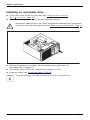
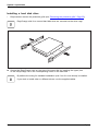
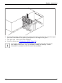
► Slide the drive into the drive carrier (1).
► Fasten the drive into place with
the screws (2).
2
1
2
2
1
► Push the drive carrier into the casing until the screw holes on the casing and the screw
holes on the drive carrier are directly one above the other (1).
► Secure the drive carrier with the screws (2).
► Connect the cables to the drive. Make sure the polarity is correct.
► Close the casing (see "Closing the casing", Page 34).
It may be necessary to modify the entry for the drive in the BIOS Setup.
36
Fujitsu
System expansions
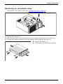
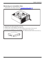
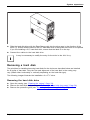
Removing an accessible drive
•
Requirement: The casing is open (see "Opening the casing", Page 33).
1
2
3
► Remove the screws (1).
► Push the drive carrier a few centimetres out of the casing in the direction of the arrow (2).
► Pull the drive carrier completely out of the casing in the direction of the arrow (3).
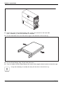
► Remove the screws (1).
► Pull the drive out of the drive carrier (2).
2
1
3
1
Fujitsu
37
System expansions
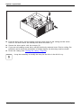
2
1
► Push the drive carrier into the casing until the screw holes on the casing and the screw
holes on the drive carrier are directly one above the other (1).
► Secure the drive carrier with the screws (2).
► If you are not installing a new drive, refit the previously removed cover. Due to cooling, fire
protection and to avoid the penetration of foreign objects, the drive bay must be closed.
► Close the casing (see "Closing the casing", Page 34).
It may be necessary to modify the entry for the drive in the BIOS Setup.
38
Fujitsu
System expansions
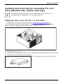
Installing and removing the accessible 51/4 inch
drive (standard size, bottom drive bay)
The following instructions apply only to the installation and removal of an
accessible drive in standard size, in the bottom drive bay.
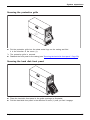
Fitting the drive cover for the 5 1/4 inch drive
• Requirement: The casing is open (see section "Opening the casing", Page 33).
To use the latch function of the accessible 51/4 inch drive, you must fit the corresponding
drive cover before installing the drive in the casing. Proceed as follows:
3
2
1
► Unlock the drive cover (1).
► Push the drive metal plate upwards (2) so it is released from the catches with which it is secured.
► Lift the drive cover away from the casing (3).
► Connect the drive cover to the drive (1).
1
Fujitsu
39
System expansions
Installing an accessible drive
► Fit the drive cover for the 51/4 inch drive (see "Fitting the drive cover for
the 5 1/4 inch drive", Page 39).
► If you have already fitted a cover in the bay (optional), remove it.
Do not throw away the cover. For cooling and protection against fire you must refit the
cover if you remove the drive again later (see "Removing an accessible drive", Page 41).
1
► Slide the accessible drive together with the attached drive metal plate into
the casing until it engages (1).
► Connect the cables to the drive. Make sure the polarity is correct.
► Close the casing (see "Closing the casing", Page 34).
It may be necessary to modify the entry for the drive in the BIOS Setup.
40
Fujitsu
System expansions
Removing an accessible drive
•
Requirement: The casing is open (see "Opening the casing", Page 33).
2
1
3
►
►
►
►
Disconnect the cables connected to the drive.
Slide the clip in the direction of the arrow (1).
Push the drive a few centimetres out of the casing in the direction of the arrow (2).
Pull the drive completely out of the casing in the direction of the arrow (3).
► Remove the drive cover from the drive (1).
1
Fujitsu
41
System expansions
1
2
► Place the drive cover on the casing (1).
► Slide the drive cover downwards (2) so that the drive cover clicks into the catches.
► If you are not installing a new drive, reinstall the cover (optional) which was
previously removed. The drive bay must be closed off to ensure cooling, to protect
against fire and to prevent the entry of foreign bodies.
► Close the casing (see "Closing the casing", Page 34).
It may be necessary to modify the entry for the drive in the BIOS Setup.
Installing/removing a 3½" reader in a 3½" bay
(optional, SmartCard or MultiCard)
Operation of the module is not permitted in Taiwan.
You can for instance install a SmartCard or MultiCard reader in the 3½" drive bay. The
reader is mounted onto a module holder when installed in the casing.
SmartCard or MultiCard readers can be mounted on a module holder (optional).
If you have ordered a device with a SmartCard or MultiCard reader, the module
holder, SmartCard or MultiCard reader are already built in on delivery.
If you have ordered a device without a SmartCard or MultiCard reader, a
blind cover is installed instead of the module holder.
42
Fujitsu
System expansions
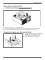
Removing the module holder
• Requirement: open the casing (see "Opening the casing", Page 33).
► Disconnect the cables connected to the module holder.
1
1
2
2
3
► Remove the screws (1) on the module holder.
► Push the module holder a few centimetres out of the casing in the direction of the arrow (2).
► Pull the module holder completely out of the casing in the direction of the arrow (3).
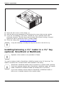
Screwing the reader onto the module holder
► With the component side facing downwards,
slide the reader in the direction of arrow (1)
into the guide on the module holder (a).
► Fasten the reader with the screws (2).
2
2
a
a
Fujitsu
1
43
System expansions
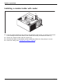
Installing a module holder with reader
2
2
1
► Push the module holder into the casing in the direction of the arrow (1) until the screw holes
on the casing and the screw holes on the reader are directly one above the other (1).
► Secure the module holder with the screws (2).
► Connect the cables to the boards and the mainboard. Make sure the polarity is correct.
► Close the casing (see "Closing the casing", Page 34).
44
Fujitsu
System expansions
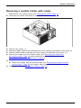
Removing a module holder with reader
• Requirement: The casing is open (see "Opening the casing", Page 33).
► Disconnect the cables connected to the module holder.
1
1
2
3
►
►
►
►
Remove the screws (1).
Push the module holder a few centimetres out of the casing in the direction of the arrow (2).
Pull the module holder completely out of the casing in the direction of the arrow (3).
Remove the reader from the module holder (see "Removing the reader from
the module holder", Page 46) and reinstall the module holder (corresponds to
"Installing a module holder with reader", Page 44).
or
► Remove the reader from the module holder (see "Removing the reader from the
module holder", Page 46) and install a blind cover in the drive bay.
► Close the casing (see "Closing the casing", Page 34).
Fujitsu
45
System expansions
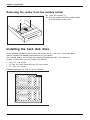
Removing the reader from the module holder
1
1
► Undo the screws (1).
► Pull the reader out of the module holder
in the direction of the arrow.
Installing the hard disk drive
In the standard installation set for hard disk drives, two 31/2 inch or 21/2 inch hard disks
may be installed as standard upon delivery of your device.
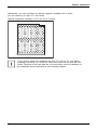
The optional add-on set includes the required EasyChange rails. The maximum
number of hard disks you can install is as follows:
• four 21/2 inch drives
• or: two 21/2 inch drives and two 31/2 inch drives
• or: four 31/2" drives
Standard assembly kit C78 for up to 4 drives:
46
Fujitsu
System expansions
Alternatively, you can purchase an optional upgrade installation kit in which
you can install up to eight 21/2 inch drives:
Optional expansion assembly kit C76 for up to 8 drives:
If you wish to switch the installation set from 31/2 inch to 21/2 inch before
installing a hard disk, you must first remove the hard disk fan and the card
holder. Removal of the hard disk fan, the card holder and the installation of
the installation set are described in the following chapters.
Fujitsu
47
System expansions
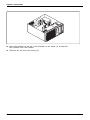
Mounting or replugging the cold plug master cable
In general, connectors P0-P3 of the cold plug master cable are preassembled in slots EP0-EP3
of the standard assembly kit. Thus, four 31/2" drives can be operated:
Assignment 1 Standard assembly kit:
Assignment 1 with connected connectors:
EP0 / P0
EP4
EP5
EP6
EP7
EP1 / P1
EP2 / P2
EP3 / P3
Slot EP0 = Connector P0 (Boot-HDD)
Slot EP1 = Connector P1
Slot EP2 = Connector P2
Slot EP3 = Connector P3
48
Fujitsu
System expansions
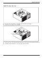
For the operation of two 21/2" drives and two 31/2" drives, the connectors must be replugged as follows:
Assignment 2 Standard assembly kit:
Assignment 2 with connected connectors:
EP0
EP1
EP2 / P2
EP4/
P0
EP5/
P1
EP6
EP7
EP3 / P3
Slot EP4 = Connector P0 (Boot-HDD)
Slot EP5 = Connector P1
Slot EP2 = Connector P2
Slot EP3 = Connector P3
Fujitsu
49
System expansions
For the operation of four 21/2" drives, the connectors must be replugged as follows:
Assignment 3 Standard assembly kit:
Assignment 3 with connected connectors:
EP0
EP1
EP2
EP4/
P0
EP5/
P1
EP6/
P2
EP7
P3
EP3
Slot EP4 = Connector P0 (Boot-HDD)
Slot EP5 = Connector P1
Slot EP6 = Connector P2
Slot EP7 = Connector P3
When replugging the cable, proceed as follows:
►
►
►
►
50
Press the locking lugs on the connectors at the old slot inwards and disengage them.
Remove the connectors from the old slot.
Replace the connector at the new slot in the correct position.
To ensure that the connectors engage correctly, always also push the locking lugs outwards.
Fujitsu
System expansions
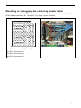
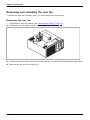
Installing a new assembly kit (for expansion
from 4 to max. 8 drives)
If you wish to upgrade your device to up to 8 drives, replace the standard assembly
kit C78 with the optional expansion assembly kit C76.
In addition to the cable for the basic configuration, you will also need an expansion cable.
EP0 / P0
EP1 / P1
EP2 / P2
EP3 / P3
EP4 / P0*
EP5 / P1*
EP6 / P2*
EP7 / P3*
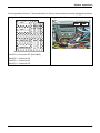
Assignment of expansion assembly kit:
Basic configuration cable:
• Slot EP0 = Connector P0 (Boot-HDD)
• Slot EP1 = Connector P1
• Slot EP2 = Connector P2
• Slot EP3 = Connector P3
Assignment of expansion assembly kit with
connected connectors:
Expansion cable:
• Slot EP4 = Connector
• Slot EP5 = Connector
• Slot EP6 = Connector
• Slot EP7 = Connector
P0*
P1*
P2*
P3*
Replacing the assembly kit
•
Requirements:
There are not any hard disk drives installed in the drive bays.
Otherwise you must first remove the hard disk drives.
• The casing is open (see "Opening the casing", Page 33).
• The hard disk fan is removed (see "Remove the hard disk fan", Page 67).
If you wish to use an installation kit for your hard disks which is other than that which
was installed in your device in the factory, proceed as follows:
Only the relevant components are shown in the following illustrations
for reasons of simplification.
Fujitsu
51
System expansions
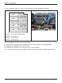
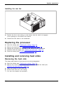
► If any hard disk drives are already installed, remove them (see "Removing a hard disk", Page 57).
► If necessary, disconnect the drive cables from the installation kit:
Press the catch to unlock it and press the cable retainer backwards out of the opening.
1
1
1
3
2
1
► Undo the screws (1) on the old installation kit.
► Slide the old installation kit in direction of the arrow (2).
► Take the old installation kit out of the casing (3).
52
Fujitsu
System expansions
3
3
3
1
2
3
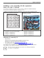
►
►
►
►
Insert the new installation kit into the casing (1).
Slide the new assembly kit in direction of the arrow (2).
Secure the new assembly kit with the screws (3).
Insert the connectors of the basic configuration cable and the extension cable (if more
than 4 drives) at the respective slot, in the correct position.
► To ensure that the connectors engage correctly, always also push the locking lugs outwards.
► Reinstall the hard disk fan (see "Install the hard disk fan", Page 69).
Fujitsu
53
System expansions
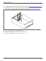
Installing hard disks
The principles for installing/removing hard disks for the device as described below are identical
for all types of hard disk. Only the size and alignment of the hard disk in the casing may
vary (install either horizontally or vertically depending on the hard disk type).
The following images illustrate the installation of a 31/2" drive.
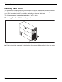
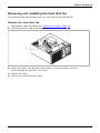
Removing the hard disk front panel
1
1
2
► Press the unlocking keys on the sides of the hard disk front panel (1).
► Fold the hard disk front panel in the direction of the arrow (2) and remove it from the casing.
54
Fujitsu
System expansions
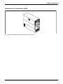
Removing the protective grille
1
► Pull the protective grille away from the casing (1).
Fujitsu
55
System expansions
Installing a hard disk drive
•
Requirement: remove the protective grille (see "Removing the protective grille", Page 55).
EasyChange rails for a second hard disk drive are mounted on the drive cage.
► Secure the EasyChange rails on the side of the hard disk by inserting the upper pins
of the EasyChange rail in the corresponding holes on the hard disk.
By default, the wiring for standard installation (max. four 21/2-inch drives) is installed.
If you wish to install other or different drives, use the supplied cables.
56
Fujitsu
System expansions
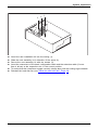
1
► Slide the hard disk drive with the EasyChange rails into the drive cage in the direction of the
arrow (1). Ensure that the label on the 3½" hard disk drive is facing the side cover to be opened.
If you are installing a 2½" hard disk drive, ensure that the label is on the top.
► Connect the cables to the hard disk drive.
It may be necessary to modify the entry for the drive in the BIOS Setup.
Removing a hard disk
The principles for installing/removing hard disks for the device as described below are identical
for all types of hard disk. Only the size and alignment of the hard disk in the casing may
vary (install either horizontally or vertically depending on the hard disk type).
The following images illustrate the installation of a 31/2" drive.
Removing the hard disk drive
► Open the casing (see "Opening the casing", Page 33).
► Remove the hard disk front panel (see "Removing the hard disk front panel", Page 54).
► Remove the protective grille (see "Removing the protective grille", Page 55).
Fujitsu
57
System expansions
1
1
2
► Press the levers of the EasyChange rails, which are secured to the hard disk
drive, outwards (1) until the hard disk is released.
► Pull the hard disk drive out of the drive cage in the direction of the arrow (2).
► Pull the EasyChange rails off the hard disk drive.
► If you no longer need the EasyChange rails, secure them again at their location in the drive cage.
It may be necessary to modify the entry for the drive in the BIOS Setup.
58
Fujitsu
System expansions
Securing the protective grille
1
► Put the protective grille into the sheet metal lugs on the casing and fold
it in the direction of the arrow (1).
The protective grille is secured.
► Reattach the front panel to the casing (see "Securing the hard disk front panel", Page 59).
Securing the hard disk front panel
1
► Place the hard disk front panel in the guide openings as illustrated.
► Fold the hard disk front panel in the direction of arrow (1) until you feel it engage.
Fujitsu
59
System expansions
Installing and removing a board
You can install additional modules in order to increase the performance of your machine.
The number, position and arrangement of the board slots on the mainboard can be found in
the manual for the mainboard. Boards may already be installed on shipment.
Board,
Installing a board
Always install display adapters with an additional power supply in slot 6. Install
a second display adapter in slot 4. The numbering of the slots can be seen on
the mainboard and from outside on the rear wall of the casing.
► Open the casing (see "Opening the casing", Page 33).
Board
11
2
1
► With long PCI boards, remove the upper part of the card holder at the front fan in
order to be able to click the board into place at the front fan during installation: Push
the locking lug on the upper, removable part of the card holder in the direction of
the arrow (1). Lift the card holder away from the fan (2).
60
Fujitsu
System expansions
1
2
► Push the mounting clip (1) towards the slot cover to unlock it, then move
it towards the back panel of the device.
► Pull the slot cover out of the slot in the direction of the arrow (2).
Do not throw away the slot cover. For cooling, protection against fire and in order to
comply with EMC regulations, you must refit the slot cover if you remove the board.
2
1
►
►
►
►
Push the board into the slot (1).
Swivel the retaining clamp back again until you feel it click into place (2).
Connect the cables to the board.
For display adapters with additional power supply: Attach the display adapter
power cable to the power supply.
Fujitsu
61
System expansions
1
► For long PCI boards, refit the upper part of the card holder at the front fan: Insert the upper
part of the card holder in the guide (1) and push it to the edge of the guide.
The upper part of the card holder engages.
► Close the casing (see "Closing the casing", Page 34).
If you have installed or removed a board, please check the relevant slot
settings in the BIOS Setup. If necessary, change the settings. Further
information is provided in the board documentation.
62
Fujitsu
System expansions
Removing a board
► Open the casing (see "Opening the casing", Page 33).
► Disconnect the cables connected to the board.
Board
11
2
1
► With long PCI boards, remove the upper part of the card holder at the front fan in order to be able
to release the board at the front fan during removal: Push the locking lug on the upper, removable
part of the card holder in the direction of the arrow (1). Lift the card holder away from the fan (2).
1
2
► Push the mounting clip (1) towards the slot cover to unlock it, then move
it towards the back panel of the device.
► Pull the board out of the slot in the direction of the arrow (2).
► Place the board in suitable packaging.
Fujitsu
63
System expansions
For cooling, protection against fire, and in order to comply with EMC (electromagnetic
compatibility) regulations, you must refit the slot cover.
2
1
► Slide the slot cover into the slot (1).
► Press on the retaining clip until it you feel it engage (2).
64
Fujitsu
System expansions
1
► For long PCI boards, refit the upper part of the card holder at the front fan: Insert the upper
part of the card holder in the guide (1) and push it to the edge of the guide.
The upper part of the card holder engages.
► Close the casing (see "Closing the casing", Page 34).
If you have installed or removed a PCI board, please check the relevant PCI
slot settings in the BIOS Setup. If necessary, change the settings. Further
information is provided in the PCI board documentation.
Fujitsu
65
System expansions
Connecting display adapters with additional
power supply
Fujitsu recommends ordering display adapters (GFX) together with the system so that
they have been installed and tested in the factory. This guarantees that the wiring
meets the requirements of the respective GFX card.
For systems that are supplied without a GFX card, a standard GFX cable is enclosed in the system
accessories pack. This enables the use of a GFX card with 6 and/or 8-pin connectors.
If you require other cables, you can purchase these from Fujitsu. The power supply (PSU)
installed in the system can supply a continuous 18.5 A for display adapters via any power
supply. Ensure that your display adapter(s) do not require higher power levels.
CELSIUS
M740
x
-
CELSIUS
CELSIUS
M740power R940
x
-
x
-
CELSIUS
R940power
x
Rated
power of
the power
supply
(PSU)
600 W
1000 W
1300 W
Continuous
current
18.5 A
18.5 A
18.5 A
Number of
GFX ports
(8 pin)
1
2
3
Upgrading main memory
► Open the casing (see "Opening the casing", Page 33).
► If the bays are located below the hard disk fan: Remove the hard disk fan
(see "Remove the hard disk fan", Page 67).
► If the bays are located below the fan at the power supply: Remove the fan at the
power supply (see "Removing the rear fan", Page 70).
► Upgrade the main memory according to the description in the manual for the mainboard.
► If the bays are located below the fan at the power supply: Install the fan at the
power supply again (see "Installing the rear fan", Page 71).
► If the bays are located below the hard disk fan: Install the hard disk fan again
(see "Install the hard disk fan", Page 69).
► Close the casing (see "Closing the casing", Page 34).
Mainmemory
66
Fujitsu
System expansions
Removing and installing the hard disk fan
To access the front main memory slots, you must remove the hard disk fan.
Remove the hard disk fan
• Requirement: open the casing (see "Opening the casing", Page 33).
► Disconnect the fan cable from the mainboard.
1
a
► Swivel the hood in the direction of the arrow (1) until the guide on the fan
(a) fits through the grooves of the hood.
► Unhook the hood.
► Remove the hood from the casing.
Fujitsu
67
System expansions
2
1
1
► Move the catches of the fan in the direction of the arrow (1) so that the
fan releases from the location.
► Remove the fan from the casing (2).
68
Fujitsu
System expansions
Install the hard disk fan
2
2
1
► Insert the fan in the casing (1) and ensure that the catches (2) engage.
► Connect the fan cable to the mainboard.
1
a
► Position the hood in the casing and slide the grooves of the hood into the guides on the fan (a).
► Carefully fold the hood down (1) until you feel it latch into place.
Fujitsu
69
System expansions
Removing and installing the rear fan
To access the rear main memory slots, you must remove the reverse fan.
Removing the rear fan
• Requirement: open the casing (see "Opening the casing", Page 33).
► Disconnect the fan cable from the mainboard.
2
1
► Press the catch of the fan in the direction of the arrow (1) so that the fan releases from the location.
► Remove the fan from the casing (2).
70
Fujitsu
System expansions
Installing the rear fan
1
2
► Position the fan in the casing (1) and ensure that the catch (2) engages
in the openings on the back of the device.
► Connect the fan cable to the mainboard.
Replacing the processor
►
►
►
►
►
Open the casing (see "Opening the casing", Page 33).
Remove the heat sink (see "Removing the heat sink", Page 71).
Replace the processor as described in the manual for the mainboard.
Install the heat sink again (see "Installing the heat sink", Page 72).
Close the casing (see "Closing the casing", Page 34).
Installing and removing heat sinks
Removing the heat sink
The shape and position of the heat sink are device-dependent.
► Open the casing (see "Opening the casing", Page 33).
► Remove the hood of the hard disk fan and the hard disk fan itself (see
"Remove the hard disk fan", Page 67).
► Undo the screws on the heat sink.
► Lift the heat sink out of the casing.
You can now replace the processor.
Fujitsu
71
System expansions
Installing the heat sink
► Open the casing (see "Opening the casing", Page 33).
► Reinstall the heat sink so that the air flow is fed towards the back of the
casing (see arrow on the heat sink).
► Tighten the screws.
► Reinstall the hard disk fan and the hood of the hard disk fan (see "Install
the hard disk fan", Page 69).
Never attach or detach fans during operation. This can cause problems
controlling the mainboard fan.
72
Fujitsu
System expansions
Replacing the lithium battery
In order to permanently save the system information, a lithium battery is installed to provide
the CMOS-memory with a current. A corresponding error message notifies the user when the
charge is too low or the battery is empty. The lithium battery must then be replaced.
Incorrect replacement of the lithium battery may lead to a risk of explosion!
The lithium battery may be replaced only with an identical battery or with
a type recommended by the manufacturer.
Do not dispose of lithium batteries with household waste. They must be disposed
of in accordance with local regulations concerning special waste.
Make sure that you observe the correct polarity when replacing the lithium
battery. The plus pole must be on the top!
Lithium battery, battery
Replacing,lithium
Replacing,
Battery
The lithium battery holder exists in different designs that function in the same way.
3
2
1
2
1
3
► Press the catch in the direction of the arrow (1).
The battery jumps out of the holder slightly.
► Remove the battery (2).
► Push the new lithium battery of the identical type into the holder (3) and
press it down until it engages.
Fujitsu
73
Technical data
Technical data
Electrical data
Safety standards complied with:
IEC 60950-1, EN 60950-1, UL 60950
Protection class:
Rated voltage range
Rated frequency
Max. rated current
CSA 22.2 No.60950-1
I
100 V – 240 V
50 Hz – 60 Hz
4 A - 9.5 A
•
Celsius M740power (1000 W PSU),
100 V – 240 V
• Celsius M740 (600 W PSU), 100 V – 240 V
Dimensions
Width/depth/height:
Weight
in basic configuration:
Ambient conditions
Environment class 3K2
186 mm x 481 mm x 430 mm /
7.32 inch x 18.93 inch x 16.92 inch
approx. 18 kg / 39.68 lbs
DIN IEC 721 part 3-3
Environment class 2K2
DIN IEC 721 part 3-2
Temperature
Operation (3K2)
10 °C .... 35 °C / 50 °F .... 95 °F
Transportation (2K2)
–25 °C .... 60 °C / –13 °F .... 140 °F
The formation of condensation is not permitted while the device is in operation !
Clearance required to ensure adequate ventilation:
without air vents
min. 10 mm / 0.39 inches
with air vents
min. 200 mm / 7.87 inches
The data sheets for these devices contain further technical data. The data sheets
can be found on our website at "http://www.fujitsu.com/fts".
74
Fujitsu
Index
Index
A
Access permission, SmartCard
Alphanumeric keypad 23
Anti-theft protection 25
Audio input 16
Audio output 16
B
Battery 73
BIOS Setup 24
security functions 27
BIOS Setup,
configuration 24
settings 24
system settings 24
Board
installing 60
removing 63
Board,
installing 60
removing 60
Button,
ON/OFF switch 23
C
Casing
Mechanical lock 26
Casing lock 26
Casing mechanical lock 26
Casing,
closing 34
lead-sealing 25
opening 33
CE marking 11
Chain 25
Components
installing/removing 31
Connecting
USB keyboard 18
Connecting a USB mouse 18
Contents of delivery 14
Ctrl+Alt+Del 24
Cursor keys 23
D
Data protection 25
Device
Connections 16
Fujitsu
27
setting up 15
Device,
anti-theft protection 25
closing 34
lead-sealing 25
opening 33
switching off 21
switching on 21
transporting 9–10
upgrades 31
Devices,
connecting 18
Disposal 10
Drivers & Utilities DVD 10
E
Electromagnetic compatibility
Energy saving 10
Ergonomic
Workstation 15
External devices
Ports 16
External devices,
connecting 18
F
Function keys
23
G
Getting started
H
Headphones
11
14
16
I
Important notes 9
Installing,
software 19–20
switching on for the first time
19
K
Kensington Lock 25
Keyboard 23
keyboard shortcuts 24
Keyboard shortcuts 23
75
Index
Keyboard,
alphanumeric keypad
cursor keys 23
function keys 23
numeric keypad 23
Keys 23
Ctrl 24
Ctrl+Alt+Del 24
Menu key 24
Keys,
Alt Gr 24
Control 24
Ctrl key 24
cursor keys 23
Enter 23
Enter key 23
menu key 24
Num Lock 24
Return 23
shift 24
shift key 24
Start key 24
L
LAN port 16
Lead-sealing 25
Line in 16
Line out 16
Lithium battery,
replacing 73
Lock 26
Low voltage directive
M
Main memory
upgrading 66
Mains adapter,
connecting 15
Microphone jack 16
Monitor,
switching off 21
switching on 21
N
Note
safety 9
Notes
CE marking 11
important 9
Numeric keypad 23
76
11
23
O
ON/OFF switch
Overview
Device 5
23
P
Packaging 14
Packaging,
unpacking 14
Ports 7, 16
Preparing for first use, overview
Preparing for use,
overview 14
Property protection 25
R
Recycling 10
Replacing,
lithium battery 73
Replacing, lithium battery
Retransportation 9–10
14
73
S
Safety information 9
Security functions
BIOS Setup 27
Security functions,
SmartCard 27
Security measures 25
Servicing 31
Setup,
see BIOS Setup 24
SmartCard reader,
operating 27
Software,
installing 19–20
System expansion 31
System settings,
BIOS Setup 24
System unit, see Device 10
T
Transportation
9–10
U
Universal Serial Bus
Upgrades,
device 31
USB devices,
connecting 18
16
Fujitsu
Index
USB port 18
connecting keyboard 18
USB port,
connecting devices 18
User Documentation DVD 10
Fujitsu
W
Workstation
15
77