1
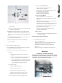
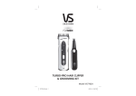
HGC-200
Hydro Gas Chlorinator
ProMinent Fluid Controls Pty Ltd
Head Office:
Unit 4, 4 Narabang Way
BELROSE NSW 2085
AUSTRALIA
(PO Box 85, BELROSE WEST NSW 2085)
Phone: (02) 9450 0995 Fax: (02) 9450 0996
Email: [email protected]
Web: www.prominentfluid.com.au
Brisbane Office:
1048-1054 Beaudesert Road
COOPERS PLAINS QLD 4108
Phone: (07) 3246 5200 Fax: (07) 3246 5225
Email: [email protected]
Melbourne Office:
Unit 2, 88 Star Crescent
HALLAM VIC 3803
Phone: (03) 8795 7430 Fax (03) 8795 7431
Email: [email protected]
Sydney, 1st August 2003
®
READ THESE INSTRUCTIONS COMPLETELY BEFORE YOU BEGIN.
Chlorine gas is potentially dangerous and should be handled with respect and care.
ProMinent
IMPORTANT
Ammonia gas should not be stored or fed in the same room with chlorine. Contact of the
gases may result in an explosive mixture.
SAFETY FIRST: Refer to AS2927
For details of wearing gas masks. Keep the cylinder wrench on the valve
for fast shut off. Have plastic squeeze bottle approximately 1/4 full of
ammonia solution for testing leaks.
1. Valve protection cover must be on Ton container & cylinders before they are moved.
2. The ton container should be level.
3. Always place Tonne container so valves are at vertical position and use only the top valve
which is the gas valve. BOTTOM VALVE IS LIQUID—DO NOT USE.
4. For best operation and safety, the Ton containers, cylinders and Chlorinators should be
protected from the elements and direct sunlight.
5. NEVER apply heaters or heat lamps directly on a Ton container or cylinder.
Corporation Cock
or
PVC Valve
®
NOTE: Unpack Chlorinator from shipping case. Check that all compenents are present and undamaged.
Piping hook-up to Ejector
A. Ejector injection point should be installed at the point of lowest
back pressure in main and at a sufficient distance downstream so
chlorinated water is not recirculated through the booster pump.
NOTE: However, where residual control is used the dosing point is
prior the take off point for booster pump.
NOTE: Booster pump suction should be 3 meters away from ejector injection point. On larger pipe diameters of 150mm or greater, a
distance of 10 times the pipe diameter should be maintained.
NOTE: Booster pump suction and ejector must be from the side of
pipeline, not from top of the main.
B. On water inlet side to ejector nozzle, a gate valve, Y strainer,
and pressure gauge should be installed in that order. Ejector
supply line size should as a minimum be the same size as ejector
inlet.
C. Attach solution hose, or PVC pipe, to discharge side of
ejector and connect via hose to injection fitting.
D. A wall mounting ejector bracket can be provided together with
injection fittings.
E. Tighten all vacuum fittings hand tight.
TESTING EJECTOR
Now test to see there is sufficient pressure to operate the ejector. Also check that the booster pump (if fitted) is operating in the
proper direction.
A. If you are operating with just city water pressure, (no booster
pump) by turning on the inlet valve to the ejector there should
be a vacuum or suction at the fitting on the side of the ejector.
5. Inspect for and remove any debris found on the chlorine
container valve or on the outlet gasket surface. Do not use a
screwdriver or sharp tool to clean.
6. Before mounting, remove all tags and tape from the
Chlorinator.
7. Loosen yoke half-dog until the valve plate can be pushed all
the way back.
8. Place new fibre or lead gasket over chlorine inlet assembly.
Never re-use the same gasket.
ProMinent
INSTALLATION OF HYDRO EJECTOR
9. Mount Chlorinator on cylinder valve with yoke over the valve
with the inlet and outlet properly aligned. Tighten the yoke
screw while making certain the gasket has not fallen out.
Excessive tightening can damage the gasket or yoke screw.
10. On Ton containers, Place weight support, found on Chlorinator
drip leg, over the lower valve.
11. On Ton containers, Warm liquid drip leg by plugging in 25watt
heater. This must be turned on 15 minutes before start-up.
CONNECTING VACUUM LINES BETWEEN CHLORINATOR AND
EJECTOR, AND CHLORINATOR VENT TO OUTSIDE
1. Upper connector on right top of Chlorinator is for 12x8
vacuum line tubing to ejector. (Allow enough vacuum tubing for
changing cylinders.)
2. Connect 12 x 8 vacuum tubing to lower connector on
Chlorinator and vent to safe area outside of building, see
AS2927. (Place insect screen outside on end of vent tubing.)
CHLORINATOR VACUUM TEST
1. Do NOT turn on chlorine cylinder valve until you have
completed vacuum test on system.
a. Vacuum test
Note 1: Ejector must have some back pressure or you will get
jetting.
Note 2: When chlorinating into a contact chamber, a tee should
be installed on the solution line with a vacuum breaker to prevent
siphoning.
B. If using a booster pump, turn on the valve in the water inlet line
and the pressure gauge should indicate a boost of at least 3 bar
greater than pressure at the booster pump inlet. If pump is operating in proper direction, there should be a strong vacuum at the
fitting located on the side of the ejector. Place your finger over the
fitting on side of ejector and you will feel the suction.
C. If the ejector has tested satisfactory, you are ready to mount
Chlorinator.
D. On start-up, the nozzle may become plugged due to filings,
solder, or other pipe debris from installation. Clear debris if
required.
INSTALLATION OF CHLORINATOR
Open the rate valve on the Chlorinator two or three turns.
With the chlorine cylinder still closed, start the ejector
booster pump,in about a minute the metering ball will drop
to the bottom of the metering tube. If the ball continues
to bounce there is either a leak at the (lead) gasket or a
loose connection at the vacuum tube fittings or meter tube.
Tighten connections and recheck. (The tube fittings should
be hand tight. It is not necessary to use pliers or wrench
on these fittings. If meter tube needs tightening, use a coin
and finger-tighten.)
b. If the ejector is operating properly, pulling sufficient
vacuum, the indicator on the front of the Chlorinator should
show red.
c. Turn off water supply to ejector.
d. Wait 5 to 10 minutes with the water supply off. Turn the
reset knob on front of Chlorinator. The indicator should
continue to show red. (If red continues to show you have a
vacuum tight system.)
1. After the chlorine cylinder has been properly installed, remove
valve protector cap.
e. You can now proceed if the system is vacuum tight.
2. Chlorine Ton container valves must be in the vertical position
with one valve directly above the other.
f. Disconnect vacuum tubing at top of Chlorinator to allow
air to enter system. Reconnect tubing.
3. Look at position of top valve, if it faces to or opens on left, a
left hand Chlorinator is required. Check Chlorinator to see if
you have a left-hand unit.
2. Turn reset on front of vacuum regulator and now it should show
grey.
4. Prior to removing valve cap covering the chlorine container
valve outlet, make certain the valve is in the closed position.
Proceed by removing the cap slowly.
NOTE: Do not connect vent lines from two Chlorinators to one
common vent. You must run separate lines to the outside when
using two Chlorinators.
®
Material necessary: A small plastic squeeze bottle, 1/4 full of
household ammonia, for checking chlorine
leaks. By squeezing the bottle the ammonia
fumes directed at the lead or fibre gasket
will show a white smoke if a chlorine leak is
present.
1. Turn booster pump on.
2. Open the rate valve on flow meter assembly for low flow
(about two full turns open).
b. Exhaust fan turn on switch should be located near out
side entrance with alternate outside turn on switch.
c. Chlorine cylinder wrench should remain on the
cylinder.
d. Plastic squeeze bottle 1/4 full of household
ammonia.
e. Buddy system used (two people capable of
operating system).
2. If a leak is detected the following should be checked first.
3. Open chlorine cylinder-valve 1/4 turn and close immediately.
Do not strike the cylinder wrench to open valve.
a. The lead or fibre gasket between the chlorine cylinder
valve and the vacuum regulator inlet assembly.
4. Squeeze ammonia bottle fumes around lead gasket at cylinder
connection and rate valve bonnet, two fittings on Chlorinator. If
chlorine is leaking, a white smoke will appear. If no smoke
appears, proceed.
(1) Tighten half dog screw on vacuum regulator yoke
assembly that is used to secure inlet assembly to
chlorine cylinder valve. (Do not use excessive force.)
(2) Always use a new gasket.
CORRECT LEAKS BEFORE PROCEEDING!
5. Turn on cylinder valve 1/4 turn and leave open. (Recheck again
for leaks.)
b. Chlorine leaking out the vent due to the Inlet safety shut
off valve having dirt on the valve seal.
(1) Turn off chlorine cylinder valve.
6. Adjust rate valve to desired rate.
7. Do not use rate valve as shut off valve. To shut off chlorine,
close the cylinder valve.
(2) Wait until the metering ball drops to zero on the flow
tube.
(3) Turn off water supply to ejector.
8. Read rate of flow at centre of ball.
SYPHONING ACTION
When EJECTOR is placed above water, the fall of water in solution
line may create a siphoning action. This may require a vacuum
break. (A “T” with a ball check valve that will allow air into solution
line when booster pump or water to ejector is turned off).
(4) Now you may remove the vacuum regulator from the
cylinder valve provided the red indicator is showing no
chlorine pressure. (RED should be showing.)
C. Servicing the inlet safety shut off valve.
(1) Remove the two screws holding the metal yoke plate to the
vacuum regulator body.
SHORT PERIOD SHUT-DOWN
1. Shut off water supply.
2. Shut off chlorine container valve. Do not use rate valve as
shut-off valve.
3. Drip leg heater remains on, on Ton container.
EXTENDED SHUT-DOWN
1. Shut off cylinder valve.
2. Turn off ejector water supply.
3. Drip leg heater must be on 15 minutes before restart on ton
container.
System will use up all chlorine in vacuum system and go on
vacuum. Before start-up you would have to break vacuum.
Use new lead or fibre gasket each drum/
bottle change. Also replace Filter material
SERVICING THE HYDRO SYSTEM
HYDRO Gas Chlorinators when operated according to instructions
will require little service. The following is concise summary to aid
you in reliable service.
1. Pressurised chlorine leaks are a safety hazard to life and
equipment and should be corrected immediately. When
searching for this type of leak there are basic safety rules to
follow.
a. Air breathing pack should be readily available.
(2) Grab the metal yoke and with a slight turning motion pull
the yoke out of the Chlorinator body.
(3) With a small screwdriver remove T-210 Filter and this will
place the valve and seat at your finger tips.
(4) Insert a small screwdriver in valve slot and hold vent plug
(it’s shaped like a bullet) and unscrew.
(5) Examine the Teflon valve seat and valve-sealing plug.
ProMinent
START-UP OF CHLORINATION
®
Teflon Seat
Solid Silver Needle
(a) Do not use screwdriver or sharp object to clean valve
plug or seat.
(b) Use a soft, clean cloth with acetone to clean valve plug,
valve seat and valve bullet.
(6) Assemble in the reverse order. Do not use pliers to hold
(bullet) use your fingers and turn slotted valve with correct
size screwdriver. Be certain you put tiny silver washer on
valve plug. Also turn seal plug back into inlet adapter hand
tight.
(7) For manifold mount clean and replace S-275 Filter. For Ton
mount fit new FG-40 Filter Pad.
(8) After mounting Chlorinator with a new gasket pull a
vacuum test before you turn on cylinder valve. See Start
Up of Chlorination.
NO CHLORINE FEED
No vacuum being produced by ejector?
1. Remove EVA tubing from ejector fitting and place your finger
on it and you should feel good suction.
(1) Shut off cylinder or Ton container valve.
(2) Remove vacuum regulator.
(3) Remove S-275 Silver filter
(4) Wash silver screen, Teflon holder, and “O” ring in
hot soapy water, rinse and air dry.
(5) Insert back in inlet assembly.
(6) Be sure to replace lead gasket
ProMinent
To clean the filter, Manifold Mount:
To clean the filter, Ton Mount:
(1) Shut off cylinder or Ton container valve.
(2) Remove vacuum regulator inlet valve.
(3) Remove two hex bolts to separate iron-work from
body plate.
(4) Filter in Inlet valve holder is Silver screen S-275 and
Fibreglass Filter Pad. Clean the silver screen as below
and replace the Filter pad FB-40.
(5) Filter in the Ironwork assembly is silver screen in
Teflon holder and can be removed by turning hex screw
into it and pulling towards you.
(6) Wash silver screen, Teflon holder, and “O” ring in
hot soapy water, rinse and air dry.
(7) Insert back in inlet assembly.
(8) Be sure to replace lead gasket between inlet
assembly and inlet adapter.
d. Out of Chlorine
Flow ball should be at zero and RED indicated on front
of vacuum regulator.
REPLACING RATE VALVE O RING SEAL
1. Turn off chlorine cylinder valve.
2. Turn off water supply to ejector.
a. Remove the RATE VALVE
b. Place piece of tape or cloth around Monel bonnet, grip
firmly with pliers and turn counter-clockwise.
c. Under bonnet you just removed sits sealing O ring.
Remove and replace new O ring, seating with eraser side
of pencil.
d. Replace Monel bonnet hand tight and install rate valve.
2. If you feel no suction or vacuum, check in this order:
a. Nozzle
(1) Turn off water supply and remove nozzle from
ejector.
(a) It may be clogged with stone or other foreign matter.
Flush out or run pipe cleaner through only.
(b) If there is a build-up of rust, iron or manganese,
place the nozzle in a muriatic acid for five minutes
and rinse with water. If you see a black syrup substance you may find it necessary to clean nozzle
on a preventative maintenance schedule.
IMPORTANT
PROCEDURE:- TAKING OUT OF SERVICE
When taking vacuum regulator out of service and not servicing
immediately, even for 1 hour, the bottle or drum inlet connection must
be plugged to prevent moisture absorption and severe corrosion.
Inlet must be serviced immediately or plugged.
b. Inlet Water Supply
(1) Reduced city water pressure.
(2) Y strainer needs clean out.
(3) Booster pump cavitating (lost its prime).
(4) Booster pump insufficient boost due to wear.
(5) Booster pump must have flooded suction.
c. Vacuum regulator inlet screens clogged or dirty
Insert plug or cork here.
CHANGING TON CONTAINERS & CYLINDERS, SAFELY
READ COMPLETELY BEFORE YOU BEGIN
SAFETY FIRST. Wear safety glasses or full face shield preferred. Air pack or gas mask should be available.
Keep the cylinder wrench on the valve for fast shut off. Have plastic squeeze bottle
of ammonia 1/4 full for testing leaks.
CHLORINE SUPPLIER - PHONE No:
1. Turn chlorine cylinder valve off (Clockwise). Be sure chlorine cylinder valve is closed and not stuck in an
open position.
2. The chlorinator rate valve should be open a minimum of 2 turns.
3. Leave ejector water on to produce vacuum, ball in meter tube should drop to bottom and indicator should
show red if cylinder valve is closed tight.
4. Reset the red indicator flag, which must continue to drop to show red. If flag does not drop to show red, you
may not have a vacuum tight system or your cylinder valve is not closed properly.
5. Be positive the chlorine cylinder valve is closed before you remove the chlorinator. SLOWLY TURN
THE YOKE SCREW LOOSE TO CAREFULLY REMOVE, THE CHLORINATOR FROM CYLINDER
VALVE. Place cap and hood on empty cylinder.
6. Secure new full cylinder. Remove hood and slowly remove cap to be sure valve is tightly closed.
7. REMOVE OLD LEAD or FIBRE GASKET AND INSTALL NEW LEAD or FIBRE GASKET ON
CHLORINATOR INLET.
8. With new gasket in place, put chlorinator on cylinder and tighten YOKE SCREW WITH
WRENCH PROVIDED. (DO NOT USE EXCESSIVE FORCE.)
9. OPEN CHLORINE CYLINDER VALVE 1/4 TURN AND CLOSE IMMEDIATELY. Check for leaks with
ammonia using plastic squeeze bottle to direct ammonia fumes around lead gasket, cylinder valve and
two fittings on chlorinator. The ammonia will appear as a white smoke if you have a chlorine leak.
If you have a leak CHLORINE WILL BE PULLED THROUGH EJECTOR TO PROCESS WATER.
***** CORRECT LEAKS BEFORE PROCEEDING *****
10. IF NO LEAKS WERE DETECTED, turn on chlorine cylinder valve 1/4 turn and recheck for
leaks. (KEEP THE WRENCH ON THE CYLINDER VALVE.)
11. Adjust feed rate to desired flow with rate valve on top of rotameter and test for free or total chlorine.
12. Be sure you understand this information before you begin. Before you ever turn on a chlorine valve, be
sure your ejector has vacuum or suction so you could feed chlorine to process water.
14. To shut down for extended period: (1 ) turn off chlorine cylinder valve, (2) turn off water supply to ejector.
15. Drip leg heater, on Ton container mounted systems, must be on 15 minutes prior to start up and
left on, during operation of Chlorinator.
ProMinent Fluid Controls Pty. Ltd.
®
ProMinent
HANG NEAR CHLORINATOR