1
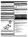
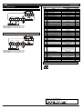
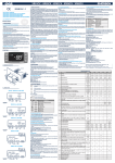
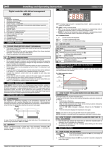
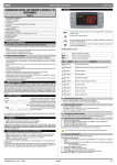
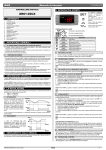
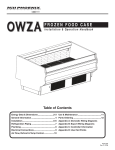
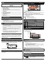
,QVWDOOLQJDQG2SHUDWLQJ,QVWUXFWLRQV
4. FRONT PANEL COMMANDS
Digital controller with off cycle defrost
XR30C
CONTENTS
1. GENERAL WARNING___________________________________________
2. GENERAL DESCRIPTION _______________________________________
3. CONTROLLING LOADS _________________________________________
4. FRONT PANEL COMMANDS_____________________________________
5. TEMPERATURE ALARM AND ITS DURATION RECORDING (HACCP) ___
6. MAIN FUNCTIONS _____________________________________________
7. PARAMETERS ________________________________________________
8. DIGITAL INPUT________________________________________________
9. INSTALLATION AND MOUNTING _________________________________
10. ELECTRICAL CONNECTIONS ___________________________________
11. HOW TO USE THE HOT KEY ____________________________________
12. ALARM SIGNALS ______________________________________________
13. TECHNICAL DATA _____________________________________________
14. CONNECTIONS _______________________________________________
15. DEFAULT SETTING VALUES ____________________________________
1
1
1
1
1
1
2
2
3
3
3
3
3
4
4
SET: To display target set point; in programming mode it selects a parameter or
confirm an operation.
(DEF) To start a manual defrost
9 (UP): To see the last temperature alarm happened; in programming mode it
browses the parameter codes or increases the displayed value.
8 (DOWN) To see the last temperature alarm happened; hold pressed it switches
the auxiliary output; in programming mode it browses the parameter codes or
decreases the displayed value.
KEY COMBINATIONS:
1.1 PLEASE READ BEFORE USING THIS MANUAL
9 +8
SET + 8
SET + 9
•
4.1 USE OF LEDS
1. GENERAL WARNING
•
•
1.2
•
•
•
•
•
•
•
•
This manual is part of the product and should be kept near the instrument for
easy and quick reference.
The instrument shall not be used for purposes different from those described
hereunder. It cannot be used as a safety device.
Check the application limits before proceeding.
To lock & unlock the keyboard.
To enter in programming mode.
To return to the room temperature display.
Each LED function is described in the following table.
LED MODE
ON
Compressor enabled
FUNCTION
Flashing -Programming Phase (flashing with
- Anti-short cycle delay enabled
ON
Defrost enabled
SAFETY PRECAUTIONS
Check the supply voltage is correct before connecting the instrument.
Do not expose to water or moisture: use the controller only within the operating
limits avoiding sudden temperature changes with high atmospheric humidity to
prevent formation of condensation
Warning: disconnect all electrical connections before any kind of maintenance.
Fit the probe where it is not accessible by the End User. The instrument must
not be opened.
In case of failure or faulty operation send the instrument back to the distributor
or to “Dixell s.r.l.” (see address) with a detailed description of the fault.
Consider the maximum current which can be applied to each relay (see
Technical Data).
Ensure that the wires for probes, loads and the power supply are separated
and far enough from each other, without crossing or intertwining.
In case of applications in industrial environments, the use of mains filters (our
mod. FT1) in parallel with inductive loads could be useful.
)
Flashing - Programming Phase (flashing with
Second relay ON
ON
An temperature alarm happened
)
$8; ON
5. TEMPERATURE ALARM AND ITS DURATION
RECORDING (HACCP)
XR30C signals and records temperature alarms, together with their duration and
max value reached. See drawing:
Ex. High temperature alarm
Tem pera ture
M ax
Tem p erature
2. GENERAL DESCRIPTION
;
A Lu
H igh te mp. alarm
Model XR30C, format 32 x 74 mm, is a digital termostat with off cycle defrost
designed for refrigeration applications at normal temperature. It provides two relay
outputs, one for the compressor, the other one can be used for alarm signalling or
as auxiliary output. The probe input can be selected between PTC or NTC. The
instrument has a digital input, for alarm signalling, for switching the auxiliary output
or for start a defrost cycle.
S et
;
;
Safe food zone
A LL
Low te mp . alarm
Alarm duration
3. CONTROLLING LOADS
Tim e
5.1 HOW TO SEE THE ALARM DURATION AND MAX (MIN)
TEMPERATURE
3.1 COMPRESSOR
The regulation is performed according to the temperature measured by the
thermostat probe with a positive differential from the set point: if the temperature
increases and reaches set point plus differential the compressor is started and then
turned off when the temperature reaches the set point value again.
If the alarm LED is on, an alarm has taken place.
To see the kind of alarm, the max (min) reached temperature and alarm duration do
as follows:
1.
Push the Up or Down key.
2.
On the display the following message is shown::
“HAL” for high temperature alarm (“LAL” fot the minimum allarm), followed by
the Maximum (minimum) temperature.
Then the “tiM” (tiMe) message is displayed, followed by the “Duration” in
h.mm.
3.
Then the instrument displays the temperature once again.
NOTE1: if an alarm is still occurring the “tim” shows the partial duration.
NOTE2: the alarm is recorded when the temperature come back to normal values
In case of fault in the thermostat probe the start and stop of the compressor are
timed through parameters “COn” and “COF”.
5.2 HOW TO RESET A RECORDED ALARM OR ONE THAT IS
STILL OCCURRING
3.2 DEFROST
1.
Defrost is performed through a simple stop of the compressor. Parameter “IdF”
controls the interval between defrost cycles, while its length is controlled by
parameter “MdF”.
2.
Hold the SET key pressed for more than 3s, while the recorded alarm is
displayed. (the rSt message will be displayed)
To confirm the operation, the “rSt” message starts blinking and the normal
temperature will be displayed.
6. MAIN FUNCTIONS
6.1 HOW TO SEE THE SETPOINT
1.
2.
1592007220 XR30C GB r1.0 15.05.2003.doc
;5&
Push and immediately release the SET key: the display will
show the Set point value;
Push and immediately release the SET key or wait for 5 seconds to display the
probe value again.
1/4
,QVWDOOLQJDQG2SHUDWLQJ,QVWUXFWLRQV
6.2 HOW TO CHANGE THE SETPOINT
1.
2.
3.
4.
Push the SET key for more than 2 seconds to change the Set point value;
LED starts blinking;
The value of the set point will be displayed and the
To change the Set value push the
or
arrows within 10s.
To memorise the new set point value push the SET key again or wait 10s.
9 8
6.3 HOW TO START A MANUAL DEFROST
Push the DEF key for more than 2 seconds and a manual
defrost will start.
6.4 HOW TO SWITCH ON OR OFF THE SECOND RELAY
(OAC= LHt)
Hold pressed the
turned ON or OFF
8
key for some seconds, till the $8; LED is
6.5 HOW TO CHANGE A PARAMETER VALUE
To change the parameter’s value operate as follows:
1. Enter the Programming mode by pressing the Set and
DOWN key for 3s (
and
start blinking).
2. Select the required parameter.
3. Press the “SET” key to display its value (now only the
LED is blinking).
4. Use “UP” or “DOWN” to change its value.
5. Press “SET” to store the new value and move to the following parameter.
To exit: Press SET + UP or wait 15s without pressing a key.
NOTE: the set value is stored even when the procedure is exited by waiting the
time-out to expire.
6.6 THE HIDDEN MENU
The hidden menu Includes all the parameters of the instrument.
6.6.1
HOW TO ENTER THE HIDDEN MENU
1. Enter the Programming mode by pressing the Set +
key
for 3s (LED 1 and
start blinking).
2. When a parameter is displayed keep pressed the Set+
for more than 7s. The Pr2 label will be displayed
immediately followed from the HY parameter.
NOW YOU ARE IN THE HIDDEN MENU.
3. Select the required parameter.
4. Press the “SET” key to display its value (Now only the
LED is blinking).
5. Use
or
to change its value.
6. Press “SET” to store the new value and move to the following parameter.
or wait 15s without pressing a key.
To exit: Press SET +
NOTE: the set value is stored even when the procedure is exited by waiting the
time-out to expire.
8
8
9 8
9
6.6.2 HOW TO MOVE A PARAMETER FROM THE HIDDEN MENU TO THE
FIRST LEVEL AND VICEVERSA.
Each parameter present in the HIDDEN MENU can be removed or put into “THE
FIRST LEVEL” (user level) by pressing “SET + ”.
In HIDDEN MENU when a parameter is present in First Level the decimal point is
on.
8
6.7 HOW TO LOCK THE KEYBOARD
1.
2.
3.
9
8
Keep pressed for more than 3 s the
and
keys.
The “POF” message will be displayed and the keyboard will be locked. At this
point it will be possible only to see the set point or the MAX o Min temperature
stored
If a key is pressed more than 3s the “POF” message will be displayed.
6.8 TO UNLOCK THE KEYBOARD
Keep pressed together for more than 3s the
will be displayed.
9 and 8 keys, till the “Pon” message
6.9 THE CONTINUOUS CYCLE
When defrost is not in progress, it can be activated by holding
the “ ” key pressed for about 3 seconds.
9
The compressor operates in continuous mode for the time set through the “CCt”
parameter. The cycle can be terminated before the end of the set time using the
same activation key “ ” for 3 seconds.
9
7. PARAMETERS
NOTE: the parameters preceded by dots are in the Hidden Menu.
REGULATION
Hy Differential: (0,1 ÷ 25,5°C / 1÷255 °F) Intervention differential for set point.
Compressor Cut IN is Set Point Plus Differential (Hy). Compressor Cut OUT is
when the temperature reaches the set point.
•
LS Minimum set point: (- 50°C÷SET/-58°F÷SET): Sets the minimum
acceptable value for the set point.
•
US Maximum set point: (SET÷110°C/ SET÷230°F). Set the maximum
acceptable value for set point.
1592007220 XR30C GB r1.0 15.05.2003.doc
Ot Thermostat probe calibration: (-12.0÷12.0°C;
-120÷120°F) allows to adjust possible offset of the thermostat probe.
OdS Outputs activation delay at start up: (0÷255min) This function is
•
enabled at the initial start up of the instrument and inhibits any output activation
for the period of time set in the parameter.
AC Anti-short cycle delay: (0÷50 min) minimum interval between the compressor
stop and the following restart.
CCt Compressor ON time during continuous cycle: (0.0÷24.0h; res. 10min)
•
Allows to set the length of the continuous cycle: compressor stays on without
interruption for the CCt time. Can be used, for instance, when the room is filled
with new products.
•
COn Compressor ON time with faulty probe: (0÷255 min) time during which
the compressor is active in case of faulty thermostat probe. With COn=0
compressor is always OFF.
•
COF Compressor OFF time with faulty probe: (0÷255 min) time during which
the compressor is OFF in case of faulty thermostat probe. With COF=0
compressor is always active.
CH Type of action: CL = cooling; Ht = heating.
DISPLAY
•
CF Temperature measurement unit:
°C=Celsius; °F=Fahrenheit. WARNING: When the measurement unit is
changed the SET point and the values of the parameters Hy, LS, US, Ot, ALU
and ALL have to be checked and modified if necessary).
rES Resolution (for °C): (in = 1°C; dE = 0.1 °C) allows decimal point display.
DEFROST
IdF Interval between defrost cycles: (0÷120h) Determines the time interval
between the beginning of two defrost cycles.
MdF (Maximum) length for defrost: (0÷255min) When P2P = n, (not evaporator
probe: timed defrost) it sets the defrost duration, when P2P = y (defrost end
based on temperature) it sets the maximum length for defrost.
dFd Temperature displayed during defrost: (rt = real temperature; it =
•
temperature at defrost start; SEt = set point; dEF = “dEF” label)
•
dAd MAX display delay after defrost: (0÷255min). Sets the maximum time
between the end of defrost and the restarting of the real room temperature
display.
ALARMS
•
ALC Temperature alarms configuration: (Ab; rE)
Ab= absolute temperature: alarm temperature is given by the ALL or ALU
values. rE = temperature alarms are referred to the set point. Temperature
alarm is enabled when the temperature exceeds the “SET+ALU” or “SET-ALL”
values.
ALU MAXIMUM temperature alarm: (SET÷110°C; SET÷230°F) when this
temperature is reached the alarm is enabled, after the “ALd” delay time.
ALL Minimum temperature alarm: (-50.0 ÷ SET°C;
-58÷230°F when this temperature is reached the alarm is enabled, after the
“ALd” delay time.
ALd Temperature alarm delay: (0÷255 min) time interval between the
•
detection of an alarm condition and alarm signalling.
•
dAO Exclusion of temperature alarm at startup: (from 0.0 min to 23.5h) time
interval between the detection of the temperature alarm condition after
instrument power on and alarm signalling.
SECOND RELAY AND DIGITAL INPUT
•
tbA Alarm relay silencing (with oAC=ALr):
(n= silencing disabled: alarm relay stays on till alarm condition lasts, y
=silencing enabled: alarm relay is switched OFF by pressing a key during an
alarm).
OA1 Second relay configuration: ALr: alarm; LHt: auxiliary; onF: always on; dEF:
do not select it!.; FAn: do not select it!.;
AoPAlarm relay polarity: it set if the alarm relay is open or closed when an alarm
happens. CL= the relay is closed; oP = the relay is open
i1P Digital input polarity: oP: the digital input is activated by opening the contact;
CL: the digital input is activated by closing the contact.
i1F Digital input configuration:
EAL = external alarm: “EA” message is displayed; bAL = serious alarm “CA”
message is displayed. PAL = pressure switch alarm, “CA” message is
displayed; dor = door switch function; dEF = activation of a defrost cycle; LHt
=switch on the second relay if oA1=LHt; Htr = kind of action inversion (cooling
– heating).
did: (0÷255 min)
with i1F= EAL or i1F = bAL digital input alarm delay: delay between the
detection of the external alarm condition and its signalling.
with i1F= dor: door open signalling delay
with i1F = PAL: time for pressure switch function: time interval to calculate
the number of the pressure switch activation.
nPS Pressure switch number: (0 ÷15) Number of activation of the pressure
switch, during the “did” interval, before signalling the alarm event (I2F= PAL).
If the nPS activation in the did time is reached, switch off and on the
instrument to restart normal regulation.
odc Compressor status when open door: no, Fan = normal; CPr, F_C =
•
Compressor OFF
OTHER
PbC Type of probe: it allows to set the kind of probe used by the instrument: PbC
= PBC probe, ntC = NTC probe.
•
rEL Software release for internal use.
•
Ptb Parameter table code: readable only.
8. DIGITAL INPUT
The free contact digital input is programmable in five different configurations by the
“i1F” parameter.
;5&
2/4
,QVWDOOLQJDQG2SHUDWLQJ,QVWUXFWLRQV
formed, far from heaters or from the warmest place during defrost, to prevent
premature defrost termination.
8.1 DOOR SWITCH INPUT (i1F = dor)
It signals the door status and the corresponding relay output status through the
“odc” parameter:
no, Fan = normal (any change);
CPr, F_C = Compressor OFF;
Since the door is opened, after the delay time set through parameter “did”, the door
alarm is enabled, the display shows the message “dA” and the regulation restarts.
The alarm stops as soon as the external digital input is disabled again. With the
door open, the high and low temperature alarms are disabled.
11. HOW TO USE THE HOT KEY
11.1 HOW TO PROGRAM A HOT KEY FROM THE
INSTRUMENT (UPLOAD)
1.
2.
8.2 GENERIC ALARM (i1F = EAL)
3.
4.
As soon as the digital input is activated the unit will wait for “did” time delay before
signalling the “EAL” alarm message. The outputs status don’t change. The alarm
stops just after the digital input is de-activated.
Program one controller with the front keypad.
When the controller is ON, insert the “Hot key” and push
key; the "uPL"
message appears followed a by flashing “End”
Push “SET” key and the End will stop flashing.
Turn OFF the instrument remove the “Hot Key”, then turn it ON again.
9
8.3 SERIOUS ALARM MODE (i1F = bAL)
NOTE: the “Err” message is displayed for failed programming. In this case push
again
key if you want to restart the upload again or remove the “Hot key” to abort
the operation.
When the digital input is activated, the unit will wait for “did” delay before signalling
the “CA” alarm message. The relay outputs are switched OFF. The alarm will stop
as soon as the digital input is de-activated.
11.2 HOW TO PROGRAM AN INSTRUMENT USING A HOT KEY
(DOWNLOAD)
8.4 PRESSURE SWITCH (i1F = PAL)
1.
2.
9
If during the interval time set by “did” parameter, the pressure switch has reached
the number of activation of the “nPS” parameter, the “CA” pressure alarm message
will be displayed. The compressor and the regulation are stopped. When the digital
input is ON the compressor is always OFF.
If the nPS activation in the did time is reached, switch off and on the
instrument to restart normal regulation.
3.
4.
5.
Turn OFF the instrument.
Insert a programmed “Hot Key” into the 5 PIN receptacle and then turn
the Controller ON.
Automatically the parameter list of the “Hot Key” is downloaded into the
Controller memory, the “doL” message is blinking followed a by flashing
“End”.
After 10 seconds the instrument will restart working with the new parameters.
Remove the “Hot Key”..
NOTE the message “Err” is displayed for failed programming. In this case turn the
unit off and then on if you want to restart the download again or remove the “Hot
key” to abort the operation.
8.5 SWITCHING SECOND RELAY ON (i1F = LHt)
With oA1= LHt it switches on and off the second relay.
8.6 START DEFROST (i1F = dFr)
12. ALARM SIGNALS
It starts a defrost if there are the right conditions. After the defrost is finished, the
normal regulation will restart only if the digital input is disabled otherwise the
instrument will wait until the “MdF” safety time is expired.
Message
Cause
“P1”
Room probe failure
8.7 INVERSION OF THE KIND OF ACTION: HEATINGCOOLING (i1F = Htr)
“HA”
“LA”
“dA”
“EA”
“CA”
“CA”
This function allows to invert the regulation of the controller: from cooling to heating
and viceversa.
8.8 DIGITAL INPUTS POLARITY
The digital input polarity depends on the “i1P” parameter.
i1P=CL: the input is activated by closing the contact.
i1P=OP: the input is activated by opening the contact
Maximum temperature alarm
Minimum temperature alarm
Door open
External alarm
Serious external alarm (i1F=bAL)
Pressure switch alarm (i1F=PAL)
Outputs
Compressor output according
to par. “Con” and “COF”
Outputs unchanged.
Outputs unchanged.
Regulation restarts
Output unchanged.
All outputs OFF.
All outputs OFF
12.1 ALARM RECOVERY
Probe alarm “P1” starts some seconds after the fault in the related probe; it
automatically stops some seconds after the probe restarts normal operation. Check
connections before replacing the probe.
Temperature alarms “HA” and “LA” automatically stop as soon as the thermostat
temperature returns to normal values and when defrost starts.
Alarms “EA” and “CA” (with i1F=bAL) recover as soon as the digital input is
disabled.
Alarm “CA” (with i1F=PAL) recovers only by switching off and on the instrument.
9. INSTALLATION AND MOUNTING
Instrument XR30C shall be mounted on vertical
panel, in a 29x71 mm hole, and fixed using the
special bracket supplied.
To obtain an IP65 protection grade use the front
panel rubber gasket (mod. RG-C) as shown in
figure.
13. TECHNICAL DATA
Housing: self extinguishing ABS.
Case: XR30C frontal 32x74 mm; depth 60mm;
Mounting: XR30C panel mounting in a 71x29mm panel cut-out
Protection: IP20.
Frontal protection: IP65 with frontal gasket RG-C (optional).
2
Connections: Screw terminal block ≤ 2,5 mm wiring.
Power supply: according to the model: 12Vac/dc, ±10%; 24Vac/dc, ±10%; 230Vac
±10%, 50/60Hz, 110Vac ±10%, 50/60Hz
Power absorption: 3VA max
Display: 3 digits, red LED, 14,2 mm high.
Inputs: 1 NTC or PTC probe.
Digital input: free contact
Relay outputs
compressor: SPST relay 8(3) A, 250Vac or
SPST relay 20(8)A; 250Vac
second relay: SPDT relay 8(3) A, 250Vac or
Data storing: on the non-volatile memory (EEPROM).
Kind of action: 1B; Pollution grade: normal; Software class: A.
Operating temperature: 0÷60 °C.
Storage temperature: -30÷85 °C.
Relative humidity: 20÷85% (no condensing)
Measuring and regulation range:
NTC probe: -40÷110°C (-40÷230°F)
PTC probe: -50÷150°C (-58÷302°F)
Resolution: 0,1 °C or 1°C or 1 °F (selectable).
Accuracy (ambient temp. 25°C): ±0,7 °C ±1 digit
The temperature range allowed for correct operation is 0÷60 °C. Avoid places
subject to strong vibrations, corrosive gases, excessive dirt or humidity. The same
recommendations apply to probes. Let air circulate by the cooling holes.
10. ELECTRICAL CONNECTIONS
The instrument is provided with screw terminal block to connect cables with a cross
section up to 2,5 mm2. Before connecting cables make sure the power supply
complies with the instrument’s requirements. Separate the probe cables from the
power supply cables, from the outputs and the power connections. Do not exceed
the maximum current allowed on each relay, in case of heavier loads use a suitable
external relay.
10.1 PROBE CONNECTION
The probes shall be mounted with the bulb upwards to prevent damages due to
casual liquid infiltration. It is recommended to place the thermostat probe away from
air streams to correctly measure the average room temperature. Place the defrost
termination probe among the evaporator fins in the coldest place, where most ice is
1592007220 XR30C GB r1.0 15.05.2003.doc
;5&
3/4
,QVWDOOLQJDQG2SHUDWLQJ,QVWUXFWLRQV
14. CONNECTIONS
15. DEFAULT SETTING VALUES
Label
Set
Hy
LS
US
Ot
OdS
AC
CCt
COn
R oom
14.1 XR30C: 8A COMPRESSOR
8(3)A250V
8(3)A250V
Aux/ N.C .
Alarm
Hot Key
Comp
COF
Line
CH
CF
rES
IdF
MdF
dFd
dAd
ALc
12Vac/dc supply: connect to the terminals 7 and 8.
24Vac/dc supply: connect to the terminals 7 and 8.
120Vac supply: connect to the terminals 7 and 8.
14.2 XR30C: 20A COMPRESSOR
Range
LS÷US
0,1÷25.5°C/ 1÷ 255°F
-50°C÷SET/-58°F÷SET
SET÷110°C/ SET ÷ 230°F
-12÷12°C /-120÷120°F
0÷255 min
0 ÷ 50 min
0.0÷24.0h
0 ÷ 255 min
°C/°F
3.0/37
2.0/4
-50,0/-58
110/230
0.0
0
1
0 ÷ 255 min
30
CL=cooling; Ht= heating
°C ÷ °F
CL
°C/°F
dE/8
20
it
30
Ab
in=integer; dE= dec.point
1 ÷ 120 ore
0 ÷ 255 min
rt, it, SEt, DEF
0 ÷ 255 min
rE= related to set;
Ab = absolute
Set÷110.0°C; Set÷230°F
-50.0°C÷Set/ -58°F÷Set
Room
MAXIMUM temperature alarm
Minimum temperature alarm
Temperature alarm delay
0 ÷ 255 min
Delay of temperature alarm at
0 ÷ 23h e 50’
start up
tbA Alarm relay silencing
n=no; y=yes
oA1 2nd relay configuration
ALr= alarm; dEF=no select it;
LHt=auxiliary; onF=always on;
Fan= no select it
AoP Second relay polarity (oA1=ALr)
oP; cL
i1P Digital input polarity
oP=opening;CL=closing
EAL=extern. alarm; bAL=lock
i1F Digital input configuration
20(8)A250V
Aux/
N.C .
Alarm
Name
Set point
Differential
Minimum set point
Maximum set point
Thermostat probe calibration
Outputs delay at start up
Anti-short cycle delay
Continuos cycle duration
Compressor ON time with faulty
probe
Compressor OFF time with faulty
probe
Kind of action
Temperature measurement unit
Resolution
Interval between defrost cycles
(Maximum) length for defrost
Displaying during defrost
MAX display delay after defrost
Temperat. alarms configuration
ALU
ALL
ALd
dAO
8(3)A250V
Hot Key
Comp
0.0
15
110/230
-50/-58
15
1.3
Y
LHt
cL
cL
LHt
regulation; PAL=press. switch;
dor=door switch; dEF=defrost;
LHt=switch on 2nd relay; Htr=
cooling - heating
Line
12Vac/dc supply: connect to the terminals 7 and 8.
24Vac/dc supply: connect to the terminals 7 and 8.
120Vac supply: connect to the terminals 7 and 8.
did Digital input alarm delay
Nps Number of activation of pressure
switch
odc Compressor status with open
door:
PbC Kind of probe
rEL Software release
Ptb Map code
0÷255min
0 ÷15
no, Fan = normal;
CPr; F_C = Compr. OFF;
Ptc; ntc
---
5
15
no
ntc/Ptc
4.0
-
Hidden parameters
Dixell s.r.l. Z.I. Via dell’Industria, 27
32010 Pieve d’Alpago (BL) ITALY
tel. +39 - 0437 - 98 33 - fax +39 - 0437 - 98 93 13
(PDLO GL[HOO#GL[HOOFRP KWWSZZZGL[HOOFRP
1592007220 XR30C GB r1.0 15.05.2003.doc
;5&
4/4