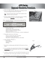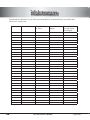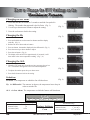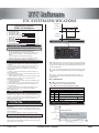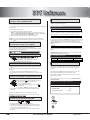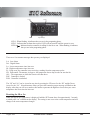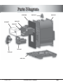
1
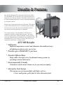
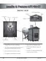
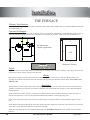
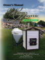
er, m Dear Custo hasing the for purc thank you ke to c. would li In ., fg M t s hwe m. We at Nort ating syste e price, h s lu P r te ompetitive c a t a t c WoodMas u prod hest quality ig h e th d il ction. al to bu It is our go total customer satisfa ur new in taining yo ta in a in a m m d n d a n a erating, talling, op s in r fo e al is a guid This manu ter Plus. tions. WoodMas ing instruc rn a w d n a safety observe all d n a w o ll Fo The Staff, r Furnaces te WoodMas Contents TABLE OF CONTENTS Contents . . . . . . . . . . . . . . . . . . . . . . . . . . . . . . . . . . . . . . . . . . . . 3 Safety . . . . . . . . . . . . . . . . . . . . . . . . . . . . . . . . . . . . . . . . . . . . . . . . 4 Features & Benefits . . . . . . . . . . . . . . . . . . . . . . . . . . . . . . . . . . . . . . . . . . . . . 5 Installation . . . . . . . . . . . . . . . . . . . . . . . . . . . . . . . . . . . . . . . . . . . 8 The Furnace . . . . . . . . . . . . . . . . . . . . . . . . . . . . . . . . . . . . . . 8 Chimney Specifications . . . . . . . . . . . . . . . . . . . . . . 8 Slab Dimensions . . . . . . . . . . . . . . . . . . . . . . . . . 8 Trench . . . . . . . . . . . . . . . . . . . . . . . . . . . . . . . . . . . . . . 8 Mounting the Pump. . . . . . . . . . . . . . . . . . . . . . . . . . . . 9 Hooking Up Water Lines . . . . . . . . . . . . . . . . . . . . . . . 9 Wiring the Pump . . . . . . . . . . . . . . . . . . . . . . . . . . . . . . 9 The Home . . . . . . . . . . . . . . . . . . . . . . . . . . . . . . . . . . . . . . . . 10 Domestic Hot Water . . . . . . . . . . . . . . . . . . . . . . . . . 10 Existing Forced Air . . . . . . . . . . . . . . . . . . . . . . . . . . 10 Existing Hot Water Heat . . . . . . . . . . . . . . . . . . . . . . . 11 Inline Filter and Fill Valve . . . . . . . . . . . . . . . . . . . . . . 11 AFS 900 Assembly . . . . . . . . . . . . . . . . . . . . . . . . . . . . . . . . . . . . . . . . . . . . 12 Operation . . . . . . . . . . . . . . . . . . . . . . . . . . . . . . . . . . . . . . . . . . . . 16 AFS 900 Startup Procedure. . . . . . . . . . . . . . . . . . . . . . . . . . . . . . . . . . 17 Adding Boiler Treatment . . . . . . . . . . . . . . . . . . . . . . . . . . . . . . . 17 AFS Series Seasonal Shutdown Procedure. . . . . . . . . . . . . . . . . . . . . . . . . . . . . . . . . . 18 Maintenance...................................................19 Boiler Treatment . . . . . . . . . . . . . . . . . . . . . . . . . . . . . . . . . . 21 Maintenance Chart . . . . . . . . . . . . . . . . . . . . . . . . . . . . 22 ETC Reference . . . . . . . . . . . . . . . . . . . . . . . . . . . . . . . . . . . . . . . . . . . . 23 Technical Wiring Diagrams . . . . . . . . . . . . . . . . . . . . . . . . . . . . . . . . . . 28 Troubleshooting...............................................31 Definitions..........................................................37 Technical Specifications . . . . . . . . . . . . . . . . . . . . . . . . . . . . . . . . . . . 38 Parts Diagram...............................................39 Parts List......................................................40 Notes ...................................................................41 Warranty & Owner’s Registration Cards (tearouts) . . . . . . . . . . . . . . . . . . . . . . . . . . . . . . . . . . . 42 May 2007 3 Safety IMPORTANT SAFETY INSTRUCTIONS READ ALL INSTRUCTIONS BEFORE INSTALLATION Pre-Installation Precautions CAUTION All installation and operations must follow STATE and LOCAL CODES for wiring, plumbing, and firing of this unit. These CODES may differ from this manual. Installation must be performed by a Qualified Installer. CAUTION Read and follow these directions carefully. Retain this manual for as long as you own your WoodMaster Plus. CAUTION All WoodMaster Plus models operate at atmospheric pressure. DO NOT obstruct, block, or plug in any way the overflow vent pipe which is located directly in front of the chimney on top of the furnace. CAUTION The chimney height may need to be adjusted depending on the installation and local codes. CAUTION Manufacturer recommends a minimum clearance from buildings or fire hazards (see pg. 8). If placed near a fire hazard area, you may want use an approved spark arrester. CAUTION Only responsible adults should operate your furnace. If furnace is not fired properly, it may result in damage and the warranty may be voided. CAUTION Never allow small children to play near or tamper with the furnace. Always keep the area around and in front of front door clean and free from combustible materials. CAUTION Do not connect this unit to a chimney flue serving another appliance. CAUTION The water pump must run continuously whenever the WoodMaster Plus is being used. Please note that your outdoor furnace is not intended to be your only heating source. CAUTION It should be used as back up or secondary heat source. Warning! Failure to operate that AFS 900 in accordance with manufacturers specifications and cautionary guidelines, will result in a voided warranty. 4 August2007 Benefits & Features How The WoodMaster PLUS Alternative Fuel System Works: The WoodMaster PLUS Alternative Fuel System operates on a simple but very efficient principle. The furnace warms water to its optimal heating temperature, which is constantly maintained by automatic controls. Heated water is then piped to the desired location. This transfer is more efficient than forced air. A circulation pump circulates the heated water to provide proper heat distribution and ensures that the desired temperature is maintained. The versatile design of The WoodMaster PLUS makes it compatible with most existing heating systems—hot water, forced air, hydronic heat, radiant baseboard, existing water-towater and radiant floor heat. Installation is easy and allows The WoodMaster PLUS to be used as a primary heat source or in conjunction with a home’s existing system. * Self Ignites AFS 900 Benefits Improves temperature control and eliminates the traditional ways of lighting your furnace for ease of use. * Provides up to 100,000 BTU’s per hour * Provides Efficient Heat Helps reduce the high costs of traditional heating systems by providing a natural alternative. * Environmentally Friendly Virtually no smoke means cleaner air for you and your family. * Alternative Fuel System This means you can burn multiple solid fuels, such as: • Corn, small grains, pellet fuels & other alternative fuels August 2007 5 Benefits & Features AFS 900-07 FRONT VIEW ETC Control Panel Water Level Light Digital Aquastat Agitating Auger Final Auger Rear Door Insulation On/Prime Switch Inside Front Tapered Throat Fire Pot Face Plate * Tapered Throat for ease of cleaning * New totally Self Igniting system * ETC panel is placed in the front of the stove for increased visibility and user access * New Modern Siding for improved aesthetics * Convenient Prime Switch for startup * New Base for improved mobility and easier access for cleaning * New highly visible Water Level Light 6 August2007 Benefits & Features AFS 900-07 BACK PANEL 6” Chimney Swirly Heat Transfer Tubes Start/Run Knobs Power Disconnect Switch Tube Access Box Insulation Door Safety Switch 120v Outlet Flip Down Door Tube Access Box Rear Control Box Tube Access Box Snap Disc Feed Auger Agitating Auger Return Line Combustion Fan (Behind Rear Control Box) Feed Auger Motor Rear Control Box Supply Line Agitating Auger & Final Auger Motor Drain Valve * Tube Access Box Door flips down for easy clean out * Improved Safety System designed to shut down your stove if any problem is detected * Rear Door is Composite with hidden hinges * Return line is a PEX fitting for effortless hook-up to prevent any risk of rusting * Rear Control box is equipped with a Power disconnect Switch August 2007 7 Installation THE FURNACE Chimney Specifications To insure proper insulation, use only a Class A Insulated Chimney and Chimney Adapter from your local WoodMaster Plus Dealer or Northwest Mfg., Inc. Concrete Pad Support Cement Pad should be at least 8 feet wide, 8 feet long, and 4 to 6 inches thick. Manufacturer recommends that you have 3 feet of clearance from the front and rear of the stove and at least 1 foot clearance on the sides. Always use a non-combustible base. 3’ Pad Dimensions (outdoor Application) 1’ Caution!! Trench AFS 1’ 3’ Minimum Clearance Call before you dig. The trench must be 24 inches deep and 6 to 12 inches wide. It can be dug with a shovel or a backhoe. Place all the dirt to one side of the trench to allow room for working on the other side. Wiring Place electrical supply in bottom of trench and cover with 6 inches of dirt. Electrical wire rated for underground use (12-2 +ground) can be buried in the same trench as the water lines but must maintain a minimum 24 inch depth. Always follow state and local codes. Water Lines The remaining 18 inches of open trench is where the water lines are placed. Use a one inch water line with a minimum rating of 100 PSI at 180 degrees and insure that your water line insulation has a minimum R-value of eight in order to maintain adequate heating efficiency. NOTE: If lines travel under a driveway or where heavy equipment travels, the line should be buried two to three feet deep. If lines travel through a low or wet area, they should be insulated and installed in a water tight piping (PVC). NOTE: Leave a minimum of three feet of water line exposed above ground at the furnace to insure adequate length for connection. NOTE: Before insulating and burying the water lines, label the hot water supply line at both ends. Once the lines are covered you will be able to easily determine which line is connected to the pump. NOTE: Use only approved water line insulation sold through your WoodMaster Plus Dealer. Poor insulation will cause major heat loss. 8 August2007 Installation THE FURNACE Mounting the Pump Hot Water Supply (On back of furnace) Attach the 1” x 2” Black Nipple (BN001) and one half of the Flanges from the 1” Cast Iron Pump Flange Kit (PF001) to one of the Hot Water Supply Valves on back of furnace. Hot Water Supply Valve Locate one of the Black Rubber Gaskets, and placing it between the Pump and the Mounted Flange, bolt the Pump to the Flange. Make sure the arrow on the pump indicating direction of water flow points down. Black Rubber Gasket (Supplied with pump) Bolt the remaining Flange and Gasket to the bottom of the Pump. Direction of Flow Indicator Arrow Pump Black Rubber Gasket (Supplied with pump) 1” Cast Iron Pump Flange Hooking Up Water Lines Hot Water Supply Attach the 1” Pex x 1” MIP (DP002) fitting to Flange on bottom of Pump. Then attach the hot water supply 1” Pex Water Line (DP001) to the fitting using 1” Pex Crimp Ring (DP007). 1” Pex Crimp x 1” MIP (DP002) Cold Water Return Attach the 1” Pex x 1” MIP (DP002) fitting to the Cold Water Return Valve on the same side of the stove on which the Pump was attached. Then attach the cold water return 1” Pex Water Line (DP001) to the fitting using 1” Pex Crimp Ring (DP007). 1” Pex Water Line (DP001) Bottom Pump Flange or Cold Water Return Valve 1” Pex Crimp Ring (DP007) Wiring The Pump Remove the cover on the Pump. Then using an approved wire, connect the Ground Wire to the Green Ground Screw on the Pump. Connect the Black Wire to the Yellow Wire on the Pump. Finally, connect the remaining two White Wires together and replace the Pump Cover. Caution!! Pump must run continously whenever the Woodmaster Plus is in use. It cannot be wired to thermostats that only runs the pump when the building calls for it. Locate Junction Box on back of stove and remove the cover. Connect the running end of the approved wire coming from the Pump to the Junction. Caution!! NOTE: The Wires from the Pump will have to connect with the Main Power Wires in the Junction Box along with the Power Wires from the ETC System. August 2007 Disconnect power before servicing any electrical components. 9 Installation THE HOME Entering the building with water lines can be done underground or over the sill plate. Once inside the building the typical hookup would run first to the Domestic Hot Water Supply and next to an existing heating system such as a forced air furnace or a hot water heating system. Finally, before leaving the building, a fill valve must be installed near enough to a water supply for filling and flushing the boiler in the WoodMaster Plus Furnace. Domestic Hot Water The Domestic Hot Water/Flatplate Kit consists of a Water to Water Heat Transfer unit and the fittings needed to hook it up. The unit mounts on the wall VERTICALLY in your utility room and is connected as shown below. WoodMaster water out WoodMaster water in Domestic Cold Water In Out to Domestic Hot Water Heater Existing Forced Air A water to air heat exchanger is inserted in the existing plenum. In most cases the heat exchanger is placed in a horizontal position, keeping all four sides level. The air must be forced through the finned area of the heat exchanger evenly. The hot water line coming from the hot-water tube enters the bottom fitting of the heat exchanger and exits the top fitting, which returns to the furnace. If the plenum is too large or too small, it must be altered to fit the heat exchanger properly. NOTE: The WoodMaster Plus Water to Air Heat Exchanger must be installed below any existing Off-Peak electric coils already in the plenum. After installation of the WoodMaster Plus add-on water to air exchanger, the air flow may need to be increased to fuel furnaces, electric furnaces, and electric/gas furnaces. Methods of doing this are: Cold Water Return to WoodMaster Plus Belt Drive System Blower pulleys and motor pulleys may be changed but the electric current flowing through the motor shall not exceed the nameplate rating. (A blower motor or larger power may be used.) Direct Drive System The motor shall not be changed, however the speed of the motor may be increased. CAUTION!! When installing heat exchangers DO NOT tamper with existing controls. Wiring to existing blower can be done with a line voltage or low voltage thermostat. Note: All wiring must follow state and local codes and should be done by a Hot Water Supply from WoodMaster Plus (Always put supply in lower port.) The heat exchanger works on the same principal as your car heater. Air blows through the heat exchanger taking the heat from the water and blowing it into your existing ductwork. qualified electrician. Wire thermostats according to directions provided by the manufacturer. 10 August2007 Installation Existing Hot Water Heat A Water to Water Heat Transfer Unit (FP520) is used to connect to an existing hot water boiler system. NOTE: Any changes to an existing boiler should be done by a qualified plumber and follow state and local codes. Existing Heat Zone Return Cold Water Return to WoodMaster Plus Hot Water Supply from WoodMaster Plus WoodMaster Plus Water to Water Heat Transfer Unit Circulating Pump for Existing Hot Water Heating System Existing Hot Water Boiler Inline Filter and Fill Valve Assembly The Inline Filter and Fill Valve Assembly (FK001) must be installed in the Cold Water Return Line before the line exits the building. It should be placed so that a washing machine hose can be connected between a domestic water supply and the Fill Valve. Cold Water Return to WoodMaster Plus Cold Water Return from Heat Exchanger August 2007 Domestic Water Supply for filling boiler 11 AFS 900 Assembly The following is a set-up guide for the AFS 900. The purpose of this guide is to give you a step-bystep set of instructions that will guide you through the assembly of the furnace and help you fire up your furnace for the first time. When you receive your AFS 900 the first thing that you should do is take inventory to ensure that you have all of the parts needed assemble the furnace. The parts you should receive are: AFS 900 (1ea.) Side Hopper w/cover (1ea.) Side Hopper Legs and Leg Supports Accessory Pack for Side Hopper 1/2 Gallon of Boiler Treatment Flue Brush w/Eye Bolt Shovel Morris Coupling Intake Auger Tube Auger Bolt Kickstand “U” Bolt Kickstand Caution!!: Make sure that the Side Hopper and the AFS 900 are installed on a level surface.Upward or downward pressure on the Intake Auger can cause the auger to bind. 12 August2007 AFS 900 Assembly A. Assembling the AFS 9001. Remove the Intake Auger Tube and Morris Coupling from the rear of the furnace, if you have not done so already. 2. Remove the “U” bolt from the Kickstand. 3. Remove the Flue Brush, Shovel, Boiler Treatment and Accessory Pack from the inside of the furnace. 4. Remove the bolt on the end of the Extension Auger. 5. Slide the Morris Coupling over the Intake Auger Tube. 6. Insert the Intake Auger through the hole in the siding. 7. Line up the flighting and attach the augers with the bolt you removed earlier. (Fig. 1) 8. Slide the Intake Auger Tube up and tighten the Morris Clamp to hold the two halfs of the Intake Auger together. 9. Slide the “U” bolt over Intake Auger and attach it to the Kickstand with the nuts supplied. Fig. 1 Fig. 2 Note: Make sure that the opening on the Intake Auger Tube is facing straight up before tightening the “U” bolt. (Fig. 2) 10. Tighten the nuts on the “U” bolt securing the Intake Auger to the Kickstand. (Fig. 3) 11. Adjust the Kickstand by sliding it up or down, if adjustment is needed Fig. 3 Note: The goal when you adjust the Kickstand is to make sure that there is no upward or downward pressure on the Intake Auger. 12. Tighten the Kickstand bolts. (Fig. 4) Fig. 4 August 2007 13 AFS 900 Assembly (continued) Fig. 1 B. Assembling the Side Hopper1. Lay the side hopper main body on it’s side. 2. Attach the legs by inserting the bolts and securing them on the inside with the nuts provided. (Fig. 1) 3. Stand the side hopper upright. 4. Attach the leg supports ensuring that the longer of the three supports is on the side of the hopper that faces the furnace. (Fig. 2) Fig. 2 Note: Install the supports on the inside of the legs, securing the supports to the legs with the “U” bolts. DO NOT TIGHTEN THE “U” BOLTS AT THIS TIME! 5. Attach the boot to the bottom of the side hopper. (Fig. 3) Fig. 3 DO NOT TIGHTEN THE CLAMP ON THE BOOT AT THIS TIME! 6. Put the top on the side hopper. 7. Secure the hopper top to the side hopper with the screws (4) provided. (Fig. 4 & Fig. 5) 8. Slide the side hopper into place next to the AFS 900. 9. Adjust the boot height and position over the Intake Auger Tube. Fig. 4 14 Fig. 5 August2007 AFS 900 Assembly (continued) Fig. 1 10. Secure the boot to the Intake Auger Tube with the clamps provided. (Fig. 1) 11. Apply the bottom boot to the end of the Intake Auger Tube and secure it with the clamp. (Fig. 2) 12. Tighten the clamp on the boot to secure it to the side hopper. 13. Raise the leg supports to a point just below the Intake Auger Tube. 14. Tighten the “U” bolts on the leg supports to secure the legs to the leg supports. (Fig. 3) 15. Remove the Chimney Cap. (Fig. 4) Note: The Chimney Cap is intended to keep rain and other elements out of the furnace when it is not in use. Store the Chimney Cap on top of the Tube Access Box when not in use. Fig. 2 16. Fill the side hopper with solid fuel. Fig. 4 Fig. 3 August 2007 15 Operation How it WorksBasic science tells us that in order to have fire we need to have fuel, air and an ignition source. The AFS 900 operates on these same principals, only in a controlled environment. In order for the AFS 900 the operate at its optimal level it needs the proper air/fuel mix. Obtaining solid fuel and air is easy, getting the proper mixture of the two is not so simple, that is why the AFS 900 have the Start & Run Knobs. Start & Run KnobsOn the side of the Rear Control Box on the AFS 900-07 there is a Start knob and a Run knob. These knobs represent the amount of fuel delivered to the Fire Pot over a set amount of time. Adjusting these knobs will increase or decrease the amount of fuel delivered, depending on the direction you turn them. Turn them to the right to increase and to the left to decrease the amount. The factory setting for these knobs are pointing straight up. Start and Run modes will be factory set to burn corn, Adjustments may be needed. Factory Settings Note: A general rule of thumb is that the heavier the fuel, the less that needs to be delivered and vise versa. After achieveing the right air/fuel mix, we need an ignition source. The AFS 900 has a built in Ignitor that will light a fire in the fire pot at start up and when ever the heating system calls for heat. In order for the Ignitor to work properly, it needs to have a constant supply of air. We produce the air flow with the Combustion Fan and control the ignition with the Air Pressure Switch and the Thermocouple. The Thermocouple will tell the Ignitor when to turn on and the Air Pressure Switch will tell it that it safe to do so. The Ignitor will attempt to ignite the solid fuel for up to 5 minutes, at which point it will either simply turn off, if the Thermocouple detects the proper amount of heat and flame, or it will shut down the whole system to prevent flooding the Fire Pot with solid fuel. Now that we have a fire burning in the Fire Pot, we need a way to control it, so we have designed a series of safety switches to do this. These safety switches, or Safety Loop as we refer to it, comprise of three switches: • • • Low Water Pressure Switch Water Snap disk Intake Auger Snap disk If any of these switches detect a problem or are not working properly, the AFS 900 will shut down and need to be reset after the issue is resolved All of this is controlled by the Main Control Module in conjunction with the Temperature Control Module and the Digital Aquastat. WoodMaster Plus AFS 900 Digital Aqua Stat Settings Set Point (SP) Spread (HY) Low Alarm (ALL) 16 170o F 1o F 120o F August2007 Start-up Procedure The following instructions make the follwing assumptions: • You already have the AFS 900 on the slab • Hooked up to the water lines with the pump • Filled with water • The heating system is installed • Power is hooked up! Fill the Side Hopper with Solid Fuel The Side Hopper holds Approximately 5.5 Bushel Ensure that you have proper water level. The Green Water Level Light Should be on. Reset the Circuit Breaker in the Rear of the Stove The Circuit Breaker Switch is located in the rear of the furnace, on the Rear Control Box. Close the Rear Door Press the Set Button on the Digital Display Important!! Make sure that all of the doors are closed for the entire Start-up process. Display will read “rst” for a second. Press the Prime Switch Solid Fuel should be visible in the Final Auger Tube and a small pile of solid fuel should be in the Fire Pot. If this has not occurred by the end of the cycle, press the Prime button again and allow it to run for another couple minutes or until you see the conditions stated above. Turn off the Prime mode by pressing the Prime Button once more. Press the On/Prime Switch to the On position Boiler Treatment- The furnace should start within 7 minutes. If this has not occured, consult the troubleshooting section (pg. 31) and try again. Allow system to burn for 2 hours and then add boiler treatment as follows. Before adding boiler treatment, be sure that the water temperature is at least 100 degrees or higher. Add the boiler treatment that came with your stove to the vent pipe located directly in front of the chimney. Treatment should be added on an annual basis. If you are interested in testing your boiler water, contact your local dealer for details. August 2007 17 AFS Series Seasonal Shutdown Procedure 1. Remove the Auger Cap. (Fig. 1) 2. Remove all solid fuel from the Side Hopper by allowing the solid fuel to pass through the bottom of the auger tube. Fig. 1 Note: Catch the solid fuel with a bucket or like container so that you do not waste any solid fuel. 3. Run the remaining solid fuel out of the intake auger by switching your furnace into Prime Mode. (see Owner’s Manual) Note: On the AFS 1100 turn T1 to the maximum setting and T2 to the minimum setting. CAUTION!!: DO NOT BURN SOLID FUEL OUT COMPLETELY! COMPLETELY! Doing so can lead to corrosion of your intake system. All solid fuel should be Primed out. 4. Thoroughly clean out the fire box: (see Owner’s Manual) •Clean the Flue Tubes •Scrape down the walls of the Fire Box •Shovel out fly ash and unburned solid fuel •Empty out Ash Bin (AFS 1100 only) •Sweep out or use a Love Less Ash Vac™ to remove remaining ash 5. Thoroughly clean the rear of the furnace: •Sweep or vacuum out the Tube Access Box •Clean the fins of the combustion fan •Wipe down everything else in the rear of the furnace 6. Apply a light film of WD-40™ to: •Drive Chains •Auger Shaft Ends •Bushings Fig. 2 7. Shut off the circulating pumps and drain all of the water out of your furnace. 8. Leave your drain valve open and rinse the furnace with water through your return line (Fig. 2), allowing the water to flow out of the drain valve until the water looks clear. 9. Add Boiler Treatment into your system and allow the pumps to run for a 24hr period in order to insure proper circulation. (see Owner’s Manual) 10. Put the chimney cap on and ensure all doors are closed tightly. 18 August2007 Cleaning & Maintenance Maintenance Schedule for the WoodMaster Plus CLEANING THE FURNACE: (Suggested Interval: Weekly) Caution!!: The pictures shown in this section show a furnace that has been neglected for photographic purposes. With normal maintenance a furnace should never look like this. 1. Clean out the Tube Access Box. (see next section) 2. Scrape down the Fire Box. (Fig. 1) 3. Shovel out the ash underneath the Firepot. (Fig. 2) Note:Try to keep the Combustion Fan and the Drive Motors as clean as possible. Clean the Combustion Fan by using a brush to keep the impeller clear of any build-up. (Fig. 3) Fig. 1 Cleaning the Heat Transfer Tubes(Suggested Interval: Weekly) ‘06 Style Swirlys: 1. Open the Tube Access Box Door. 2. Remove the Swirlys from the Heat Transfer Tubes. (Fig. 4) Caution!!: The Swirlys will be hot. 3. Run the steel brush in and out of each tube several times.(Fig. 5) 4. Clean out all ash that is left in the Tube Access Box. Note: When cleaning out your furnace, using an Ash Vacuum does an excellent job in ash removal . To inquire about Ash Vacuums please contact your representative. Fig. 2 5. Put Swirlys back in the Heat Transfer Tubes and close the door. Note: A Shovel and Flue Brush is provided. CAUTION!!: Your warranty does not cover ash corrosion. Neglecting to clean your furnace or cover the chimney when not in use, will void the warranty. Fig. 3 August 2007 Fig. 4 Fig. 5 19 Cleaning & Maintenance ‘07 Style Swirlys: (Interval: Weekly) Fig. 1 1. Insert the Eye Bolt that was provided into the chuck of a drill. Note: The Eye Bolt is shipped attached to the Flue Brush 2. Switch the drill into reverse. 3. Open the Tube Access Box Door. 4. Insert the Eye Bolt/Drill into the holes in the Swirly. (Fig. 1 & 2) Fig. 2 Note:Running the drill in Reverse will push all of the ash out of the front of the transfer tubes. It will then fall into the Fire Box for removal. (Fig. 3) 5. Clean out all ash that is left in the Tube Access Box and close the door. Note: When cleaning out your furnace, using an Ash Vacuum does an excellent job in ash removal . To inquire about Ash Vacuums please contact your representative. Fig. 3 Note: A Shovel, Flue Brush and Eye Bolt is provided. Annual maintenance: Annual maintenance should be performed in the spring when you shut down the furnace for the season. 1. Drain and flush your furnace. (refer to Boiler Treatment Procedure section below) 2. Clean all of the ash from the Tube Access Box. 3. Clean the Heat Transfer Tubes. 4. Clean out the Fire Box and Fire Pot. a. To clean the Fire Pot, remove the 4 nuts in the front face plate. b. Use a vacuum to clean the fly ash out of the air chamber. Fig. 4 Note: A Love Less Ash® vacuum cleaner works very well for ash removal and can be purchased by contacting a factory authorized dealer. 5. 6. 7. 8. Shovel out the Fire Box. Blow any visible dust off of the motors, pumps, fans, etc. Apply a light film of oil to all chains. Make sure to cover the chimney to prevent water from getting into your furnace when not in use. (Fig. 4) 20 August2007 Cleaning & Maintenance BOILER TREATMENT PROCEDURE: 1. 2. 3. 4. 5. 6. Open Drain Valve and let stove empty completely. To flush -- leave Drain Valve open and close Supply Line. Add water to furnace through the Return Line. Let flush for several minutes. Close Drain Valve and open Supply Line. Refill the stove and treat water right away. Return Line Supply Line Drain Valve CAUTION!!: Leaving your stove empty exposes the water jacket to oxygen which will shorten the life of your stove. If your system has anti-freeze, you do not need to drain it. However you should then test your water annually. For water sampling contact your dealer. August 2007 21 Maintenance To maintain the efficiency of your furnace the manufacturer recommends that you preform these checks on a weekly basis. Date 22 Clean Fire Box Clean Heat Trans- Clean Fan and fer Tubes Motors Check Chain Tension and Adjust Accordingly August2007 ETC Reference AFS 900 Electronic Temperature Control (ETC) Function: (Factory Settings below) • The ETC monitors and controls the AFS 900 water temperature by controlling the draft fan and fuel supplied. • During normal operation (adequate fuel supply) the controller will go into idle mode when the water reaches 170° F (Set) and will go into heating mode when the water falls to 169° F (Set - Hy). • During shut down (no fuel supply) or when the water falls to 120° F (ALL) the controller will go into shut down mode. At this time the AFS 900 hopper will need to be filled with fuel and the ETC will need to be reset (see Startup). Heating Mode: During the heating mode the controller will run the draft fan continuously. The controller will also turn on the heating mode timer that controls the amount of fuel added to the Fire Pot. Idle Mode: When the water temperature reaches 170o, it will shut the motors and fan off until the water temperature falls to 169o, at which point it returns to the Heating Mode. Startup / Reset: (See also AFS 900 Startup Procedure). • The first time the AFS 900 is powered up or when it has shut down, the controller display will flash “LA” (Low Alarm) two times and then display the water temperature for two seconds and then start over. This is normal and indicates the system has shut down because the water is at or below 120° F. • To start up (or reset) your AFS 900, press the set button one time. The display will indicate “rSt” (reset) and after 1 to 2 seconds the AFS 900 will go into heating mode. The display will continue to flash “LA” and the water temperature until the water temperature reaches 140° F (ALL + 20). After water temperature reaches 140° F, only the water temperature will be displayed until the water temperature falls to 120° F. • Note: The switch must be in the on position. • Note: Switch can be shut off when loading or servicing the AFS 900. Parameter Description and Factory Settings: • Set (Set Point) — 170° F • Hy (Differential) — 1°F • ALL (Low Alarm) — 120° F How To: • View Set Point — Push and immediately release the set key, display will indicate set point and will return to water temperature after 5 seconds. • Change the Set Point — Push and hold the set key until the set point is displayed, change the value using the up and down arrows, and press the set key. The set point value will flash a few times and then the display will return to water temperature. • Change Hy or ALL — Push and hold the set and down arrow keys at the same time until HY is displayed. Using the up and down arrows, select the parameter to be changed (Hy or ALL), push the set key once (value of parameter should be displayed), use arrows to change value, and push the set key (value should flash a few times). After 10-15 seconds the display will change back to water temperature. Note: When changing parameters, make sure Set-Hy is at least 20° F above ALL. Green Float Light: Plunger Switch: On/Prime Switch: Water Safety Switch: August 2007 Green light on: Water level O.K. Green light off: Water level low, add water through vent pipe or Inline Fill Valve. Shuts the Combustion Fan off during mode and operates the Service Light. The On/Prime switch must be on during normal operation, but may be turned off for maintenance. The Water Safety switch shuts down all operation of the stove if the water level is too low. 23 How to Change the ETC Settings on the WoodMaster Furnaces Changing the Set Point 1. Press and hold the set button for 3 seconds or until the fan symbol is flashing. The number that appeared is the Set Point. (Fig. 1) 2. Use the up or down arrow buttons to adjust the setting. (Fig. 1) 3. Press the set button to lock in the setting. Changing the Hy (Fig. 2) 1. Press and hold the arrow down and set buttons until the display reads Hy. (Fig. 2) 2. Release the arrow down and set buttons. 3. Press set button, the number displayed is the differential. (Fig. 3) 4. Press the arrow up or down button to adjust. (Fig. 3) 5. Press the set button. (Fig. 6) 6. The display will read ALL for approximately 30 seconds, it will then return to the water temperature reading. (Fig. 7, 8) (Fig. 4) Changing the ALL 1. When the ETC reads ALL from the previous step press the set but ton. The number that appears is the Low Alarm temperature. (Fig. 5) 2. To adjust the number press the up or down arrow. 3. Press the Set button to lock in the setting. Definitions Set Point- The temperature at which the fan will shut down. (Fig. 6) Hy- aka Differential- The amount, in degrees, the temperature has to drop in order to start the fan. ALL- aka Low Alarm- The temperature at which the furnace will shut down. Caution!! Do not set your (SP) lower than your (ALL)! WoodMaster Plus AFS Digital Aqua Stat Minimum and Maximum Settings WoodMaster Plus AFS Digital Aqua Stat Settings Set Point (SP) Differential (HY) Low Alarm (ALL) 24 170o F 1o F 120o F Factory Settings Corn Set Point (SP) Differential (HY) Low Alarm (ALL) 100o F to 180o F 1o F to 45o F -67o F to 302oF August2007 ETC Reference ETC SYSTEM SPECIFICATIONS Temperature Digital custom controller XR30C for WoodMaster Contents 1. General Warning 2. General Description 3. Controlling Loads 4. Front Panel Commands 5. Temperature Alarm and Its Duration (HACCP) 6. Main Functions 7. Parameeters 8. Alarm Signals 9. Default Setting Values Set Point Set Point- Hy 1 1 1 1 1 2 2 2 2 Time Fan ON Heating 4. Front Panel Commands LED 1 1. General Warning 1.1 Please Read Before Using This Manual • This manual is part of the product and should be kept near the instrument for easy and quick reference. • The instrument shall not be used for purposes different from those described hereunder. It cannot be used as a safety device. • Check the application limits before proceeding. • Some parameters, such as CH are not applicable to Wood master, see default settings grid fig. 15 on next page. 1.2 Safety Precautions • Check the supply voltage is correct before connecting the instrument. • Do not expose to water or moisture: use the controller only within the operating limits avoiding sudden temperature changes with high atmospheric humidity to prevent formation of condensation. • Warning: disconnect all electrical connections before any kind of maintenance. • Fit the probe where it is not accessible by the End User. The instrument must not be opened. • In case of failure or faulty operation send the instrument back to the distributor or to “Dixell s.r.l.” (see address) with a detailed description of the fault. • Consider the maximum current, which can be applied to each relay (see technical data). • Ensure that the wires for probes, loads and the power supply are separated and far enough from each other, without crossing or intertwining. • In case of applications in individual environments, the use of mains filters (our mod. FT1) in parallel with inductive loads could be useful. Model XR30C, format 32 x 74 mm, is a digital thermostat. It provides two relay outputs, one for the fan, the other one for alarm signaling. The probe input can be selected between PTC or NTC. The instrument has a digital input, for alarm signaling, or for switching the auxiliary output. 3. Controlling Loads o (UP):nTo see the last temperature alarm that occurred; in programming mode it browse the parameter codes or increases the displayed value. o (Down): To see the last temperature alarm that occurred; in programming mode it browse the parameter codes or decreases the n displayed value. Key Combinations: o+ n To lock & unlock the keyboard. n To enter in programming mode. SET + o SET + To return to the temperature display. 4.1 Use of LEDs MODE ON Flashing LED1 Flashing LED2 ON FUNCTION - Output enabled - Programming Phase (flashing with LED1) - Anti-short cycle delay enabled - Programming Phase (flashing with ) - Temperature Alarm has happened, LED2 stays on until reset 5. Temperature Alarm and Its Duration The Regulation Output The regulation is performed according to the temperature measured by the probe. The instruments are provided with the CH programmable parameter, which enables the user to set the regulation both for heating or cooling applications. CH = Ht: heating applications, which is the application here. 3.2 CH = HT: Heating Application The Hy value is automatically set under the Set Point. If the temperature decreases and reaches set point minus differential the regulation output is activated and then turned off when the temperature reaches the set point value again. August 2007 Set: Displays the target set point, selects and confirms a parameter in the programming mode. Also used in conjunction with (up) and (down) to view the Min. and Max recorded temperatures and to reset the stored temperatures. LED 2. General Description 3.1 LED 2 Example of Low temperature alarm Temperature Max Temperature ALu High temp. alarm Set ALL Low temp. alarm 25 ETC Reference o n 6.5 TO UNLOCK THE KEYBOARD 5.1 HOW TO SEE THE ALARM DURATION AND MAX (MIN) TEMPERATURE If the LED2, the alarm LED is on, an alarm has taken place. Keep pressed together for more than 3s the o displayed. n “Pon” message will be To see the kind of alarm, the max (min) reached temperature and alarm duration do as follows: 7. PARAMETERS 1. Push the UP or Down key. 2. On the display the following message is shown: “HAL” for high temperature alarm (‘LAL” for the minimum alarm), fol lowed by the Maximum (minimum) temperature. Then the “tiM” (tiMe) message is displayed, followed by the “Duration” in h.mm. 3. Then the instrument displays the temperature once again. o n Hy Differential: (0,1 ÷ 25,5°C / 1÷255 °F) Intervention differential for set point. Compressor Cut IN is Set Point Plus Differential (Hy). Compressor Cut OUT is when the temperature reaches the set point. o 5.2 HOW TO RESET A RECORDED ALARM OR ONE THAT IS STILL OCCURRING o n AFH Differential for alarm recovery: (1 ÷ 45 0F) It sets the value above the alarm value for alarm recovery. HOW TO CHANGE THE SET POINT 8. ALARM SIGNALS Push and immediately release the SET key: the display will show the Set point value; Message Cause o Push and immediately release the Setnkey or wait for 5 seconds to display the probe value again. “LA” o HOW TO CHANGE THE SET POINT o 6.2 HOW TO CHANGE A PARAMETER VALUE To change the parameter’s valuej operate as follows Enter the Programming mode by pressingothe n Set and DOWN key for 3s ( and start blinking).j Outputs Outputs unchanged Probe alarm “P1” starts some seconds after the fault in the related probe; it automatically stops some seconds after the probe restarts normal operation. Check connections before replacing the probe. Temperature alarms “HA” and “LA” automatically stop as soon as the thermostat temperature returns to normal values. Alarms “EA” and “CA” (with i1F=bAL) recover as soon as the digital input is disabled. n n o Alarm “CA” (with i1F=PAL) recovers only by switching off and on the instrument. j 9. DEFAULT SETTING VALUES 1. Select the required j parameter. 2. Press the “SET’ key to display its value (only j LED is blinking). j 3. Use “UP” or “DOWN” to change its value. 4. Press “SET” to store the new value and move to the following j parameter. To exit: Press SET + UP or wait 15s without pressing a key. Minimum Temperature alarm o 8.1 ALARM RECOVERY n 1. Push the SET key for more than 2n seconds to change the Set point o value; n 2. The value of the set point will beodisplayed and the LED1 starts blinking; n 3. To change the Set value push the or arrows within 10 s. o push n the SET key again or wait 4. To memorize the new set point value o n n 10s. no Display ALL Minimum temperature alarm: (-50.0 ÷ SET°C;58÷230°F) when this temperature is reached the alarm is enabled and the fan will shut off. 6. Main Functions o n Regulation Alarm 1. Hold the SET key pressed for more than 3s, while the recorded alarm is displayed. (The rSt message will be displayed) 2. To confirm the operation, the “rSt” message starts blinking and the normal temperature will be displayed. 6.2 keys, till the CF Temperature measurement unit: °C=Celsius; °F=Fahrenheit. WARNING: When the measurement unit is changed the SET point and the values of the parameters Hy, LS, US, Ot, ALU and ALL have to be checked and modified if necessary). rES Resolution (for °C): (in = 1°C; dE = 0.1 °C) allows decimal point display. NOTE: if an alarm is still occurring the “tim” shows the partial duration. NOTE: the alarm is recorded when the temperature comes back to normal values 6.1 and WoodMaster Plus AFS 900 Digital Aqua Stat Settings Set Point (SP) Spread (HY) Low Alarm (ALL) 170o F 1o F 120o F j NOTE: the set value is stored evenowhennthe procedure is exited by waiting for the time-out to expire. o n o n o n 6.2 HOW TO LOCK THE KEYBOARD 1. Keep pressed for more the 3s the and keys. 2. The “POF” message will bej displayed and the keyboard will be locked. At this point it will be possible only to see the set point or the MAX or Min temperature stored. jbe 3. If a key is pressed for more than 3s the “POF” messageowill n displayed 26 August2007 ETC Reference LED 3 LED 1 o n o n o n n o LED 2 Digital Display LED 1- When flashing, it indicates that you are in the programing phase. LED 2- Indicates that an alarm has occured. LED will not turn off until the system is reset. LED3 or - Indicates that the controller is calling for the fan to run. When flashing, it indicates that you are in the programing phase. These are a few common messages that you may see displayed: LA- Low Alarm DA- Digital Alarm Lo- Lowest temperature since last reset. Hi- Highest temperature since last reset. P1- Probe error, the controller is not receiving a reading from the temperature probe. HY- Differential- The amount, in degrees, the temperature has to drop in order to start the fan. ALL- The temperature at which the furnace will shut down. POF- Controller is locked. PON- Controller is unlocked. The “Hi” and “Lo” can be viewed at any time by pressing the UP Arrow for the “Hi” and the Down Arrow for the “Lo”. In both instances when you press the button the proper message will flash on the display, after that you will see a number, this number represents the highest or lowest that your water temperature has been since the last reset. Resetting the Hi or LoWhile the high or low temperature is displayed, hold the SET button down for approximately 3 seconds at which point “rst” will flash on the display. The setting is now reset to the current emperature and will change as the water temperature changes. August 2007 27 Wiring Diagrams AFS 900-07 28 August2007 Wiring Diagrams AFS 900-07 August 2007 29 Wiring Diagrams AFS 900-07 30 August2007 Troubleshooting If furnace is not heating 1. Make sure back door is closed. When open, the safety switch will not allow the system to run. 2. Check pump. If pump is not running, shut off power supply to pump and inspect. 3. The AFS 900 has a safety shut off switch for extremely low water level. If water is low, fill the stove with water until the light comes on, there will be some evaporation. 4. Check chimney for fly ash build-up. If opening is reduced fire cannot burn properly. 5. Check Fan Draft. Make sure that it is operating properly. 6. If water temperature is reading 119° or lower, push Reset Switch on ETC System to restart Heating Mode. 7. If the fire goes out and there is a lot of unburned fuel in the Fire Pot, the Start and/or Run Mode may be set to high. 8. If the fire goes out and the Fire Pot is empty, the Feed System is empty (out of fuel). 9. Feed System plugged. Possible Causes: 1. 2. 3. August 2007 Chain Drive System failure. Feed Intake plugged or blocked. Faulty motor in system. 31 Troubleshooting Note: When disconnecting any wire lead, pull on the insulated terminal not the wire!! Question or Issue Possible Solutions 1. Do I have to have the AFS 900 and Side Hopper on a level surface? The manufacturer recommends that the furnace and side hopper are placed on a level surface. There are two very important reasons for this. First, the water level in the furnace is critical to the performance of the furnace, thus the furnace needs to be on level ground in order to get a proper reading of the water level. Second, the AFS 900 and the side hopper need to be properly aligned with each other so that no undue stress is put on the drive system. If the load of the side hopper is applying pressure upward or downward on the infeed auger, it can cause the auger to bind and interrupt the delivery of fuel to the furnace. 2. How much Solid Fuel should I be burning? The amount of fuel that you are burning in any given period of time depends on several different factors: a. The type of solid fuel that you are burning and the moisture content. -corn, wood pellets, soy beans, rye, ect... b. The heat load that you are pulling off of your system at any given time. -Are the different parts of your system running? - heat exchanger, water heater, floor heat, ect... c. Loss of heat due to your systems design. - poor insulation, long water line runs, having too big of a heat exchanger in the system, ect... 3. What kind of Solid Fuels can I burn? Though the factory settings are set to burn corn (see question #6), you can burn many different solid fuel types. a. Most granular fuels. -rye, wheat, barley, soy beans, ect... b. Most pelletized fuels. -agra fuels, wood pellets, paper pellets, grass pellets, ect... 4. What do the Start and Run Knobs do? The start and run knobs adjust the rate that solid fuel is delivered to the burn area of the fire pot for the start and run modes. This does not effect the overall amount of solid fuel that you are burning or the BTU’s produced by the AFS900 directly. It adjusts the quality of burn for the type of solid fuel that you are burning. 32 August2007 Troubleshooting Note: When disconnecting any wire lead, pull on the insulated terminal not the wire!! Question or Issue 5. Where are the Start and Run Knobs located? Possible Solutions In the AFS 900-06 (tin roof) the knobs are located behind the ETC panel on the right side of the furnace toward the front. On the AFS 900-07 (composite roof) the knobs are located on the side of the rear control panel in the rear of the furnace. The knobs are sent out of the factory pointing straight up 6. What are the Start and Run Knob facor at the 12 o’ clock position. These settings are to burn tory settings? approximately 52 lb. corn at 14% moisture. 7. How do I adjust my Start and Run Knobs? Why do I need to? Too Lean Too Rich You may need to adjust the knobs in order to achieve the proper burn for the type of solid fuel that you are burning. To lean back the amount of solid fuel delivered turn the knob slightly counterclockwise. To increase the amount of solid fuel delivered turn the knob clockwise. Adjusting these knobs controls the position of the burn area and how efficient the solid fuel gets burned. Using corn as an example, you want the ash coming off the end of the fire pot to be either ash or look like ash in the shape of a piece of corn. This ash should crumble when you touch it. Caution!! Burn Area Allow the ash to cool before attempting to touch it. The burn area location should be about at the first piece of flighting. If it is right against the rear wall of the fire pot you need to increase the amount of solid fuel delivered slightly. If it is too far out on the auger you need to decrease the amount of solid fuel delivered slightly. 8. What are the Start and Run Modes? August 2007 The Start Mode refers to the period of time between when you flip the On/Prime switch to the “On” position and the point at which the fire reaches adequate burn temperature. The Start Modes generally lasts 2 minutes, but can last a maximum of 5 minutes before the furnace shuts down. The Run Mode is the normal operating mode of the furnace. This takes place after the Start Mode and continues until the furnace shuts down, the ETC is reset, or the rear door is opened and closed; at which point the furnace will go back into the Start Mode. 33 Troubleshooting Note: When disconnecting any wire lead, pull on the insulated terminal not the wire!! Question or Issue 9. What should my Start/Run settings be set at to burn a particular type of fuel? 10. My water level light won’t come on. Possible Solutions Please see question #7 in this guide. 1. Check your water level to ensure that you have the proper amount of water in the furnace. 2. Check the High Water Pressure Switch located just above the left side of Chimney Box in the rear of the furnace. There will be two switches there, you should be looking at the one on the left, marked with (4” or just the number 4). Check to see if this switch is working by checking the continuity with a multi meter. 3. Replace the light or the bulb. 11. How do I test my thermocouple? Use a multi meter in the low ohm setting to get a reading from the Thermocouple. If the switch is good, the multi meter should read 1 ohm. 12. My auger seems to be jamming? Please refer to question #1 in this guide. 13. The green light on the On/Prime Switch won’t come on. The On/Prime Switch light relates directly to the safety loop on the AFS 900. When the light is on, all of the switches in the safety loop are working. When the light is off there is a problem with one of the three switches in this loop. Check the continuity of the Intake Auger Snap Disk, Low Water Pressure Switch and Water Snap Disk. Replace or reset the switch if necessary. Note: Whenever you replace or reset a switch, you must reset the Circuit Breaker, press the set button on the Digital Aquastat and prime for 2 minutes on your furnace before you can restart the furnace. 14. Why is there a cover over my air pressure switch? The dust cover is in place to keep contaminants from entering the atmospheric pressure hole on the top of the switch. 34 August2007 Troubleshooting Note: When disconnecting any wire lead, pull on the insulated terminal not the wire!! Question or Issue Possible Solutions 15. How do I know my plunger switch is working properly? Provided that you have a good light bulb in the receptacle, when the plunger switch is working properly the Service Note: Opening the door and then closing it Light will come on and the fan will not run when the rear again will restart the start mode every time. door is opened. 16. My Ignitor seems to not be working? Your furnace needs to be in the Start Mode and there cannot be flame present in the Fire Pot in order for your Ignitor to be on. With that in mind if your Igniter doesn’t seem to be working, try these steps: 1. Check the ohm reading a. Disconnect the wire leads b. Read the ohms coming off of the Ignitor. The reading should be around 17.5 ohms. 2. Check to see that your Air Pressure Switch is working properly. (see question #17) 3. Check to see that the Thermocouple is functional. (see question #11) 17. How do I check the Air Pressure Switch ? Caution!!! Do Not Hot-wire or Jump This Switch!! The Air Pressure Switch is a normally open switch that detects the air pressure coming off of the fan. When the air pressure from the fan is to the proper level, the switch will close and the circuit will be complete, allowing the furnace to run properly. To ensure that the switch is operational, check these things: 1. Make sure that the fins on the fan’s impeller are clean. - The fan needs to produce a certain amount of CFM in order to activate the switch, so if the impeller is dirty it will hinder the fans performance. 2. Check the continuity of the switch with a multi meter. - With the button on the plunger switch out, you should read an infinite number. - With the button on the plunger switch de pressed, you should read “0”. August 2007 35 Troubleshooting Note: When disconnecting any wire lead, pull on the insulated terminal not the wire!! Question or Issue Possible Solutions -Check to see that you have solid fuel in the hopper. -Check to ensure that your augers are feeding the furnace. -The Final Auger should be full of solid fuel. -Check the settings of the Start and Run Knobs, adjust accordingly. 18. My stove won’t stay lit? 19. What is the heat output of the furnace? 20. How much current does my furnace draw? 100,000 BTU’s per hour. Maximum amp draw is 9 amps, however this is not attainable unless every piece of equipment on the AFS 900 is running at the same time. Please refer to the Technical Specifications section. (pg. 37) 21. How often should I be cleaning the ash out of the furnace? The manufacturer recommends that you clean out the ash once every week. After the ash falls off of the end of the Fire Pot, it will compress itself over time and breakdown into a finer ash. So though it may look like you need to clean it every day, leave it be. It just needs to break down. 22. What do I do if the furnace runs out Start by allowing the unit to cool sufficiently. Reset the of solid fuel? Intake Auger Snap Disk, refill your hopper and follow the start procedure on page 17 of this guide. 23. What do I do if my furnace runs out Refill your furnace with water and follow the restarting of water? procedure on page 17 of this guide. Most likely you have a safety loop failure. Reset or replace the appropriate switch and restart. 25. What happens when I open my back Whenever you open the rear door of the furnace the furnace shuts off until you close the door, at which point door? the furnace will go back into the Start Mode. 24. Only my final auger is running, what’s wrong and how do I fix it? 36 August2007 Definitions Air Chamber- The area below the Fire Pot that preheats the combustion air. AFS- Alternative Fuel System Combustion Fan- Delivers the combustion air to the Fire Pot. ETC (Electronic Temperature Control)- The electronic system that is used to control the function of the furnace. Fire Box- The inside of the furnace. Fire Pot- The area where the air is mixed with the fuel to cause combustion. Hopper- Holds the fuel that is augered into the furnace. Run Mode/Cycle- The ETC function that is used to maintain proper fuel combustion at a set temperature. Start Mode/Cycle- The ETC function that is used to create the proper amount of combustion heat before entering Run Mode/Cycle. Note: This can be altered when the start control knob is adjusted to increase or decrease fuel amounts. August 2007 37 Technical Specifications AFS900 Model Maximum Current Draw.................9amps @ 120v, 60Hz Primary Current Draw.................... Drive Motors .65amps @ 120v AC each, 60Hz Combustion Fan .62amps @ 120v AC, 60Hz Igniter 6.66amps @ 120v AC, 60Hz Lamp Holder w/ factory recomended 60 watt light bulb .5 amps @ 120v AC, 60Hz Heat Capacity..................................Up to 100,000 BTUs Hopper Capacity.............................Approximately 5.5 Bushel Fire Box Size..................................23 ½ inches deep x 24 inches tall x 22 inches wide Door Size........................................16 inches x 16 inches Thickness........................................3/16 inch fire drum and water jacket Draft Control...................................Fan Temperature Control.......................Digital electronic temperature control Overall Size....................................3.75 feet wide x 4.33 feet deep x 5.8 feet tall (including the chimney) Types of Solid Fuel that can be used............................. Corn, wood pellets, or most other granular fuels Refueling....................................... Automated on a timer; fuel fed through a hopper With a self-igniter Weight.............................................940 pounds Water capacity.................................60 gallons ATTENTION!!: Maximum amp draw can only be obtained if all devices are running at the same time and that rarely occures. 38 August2007 Parts Diagram 0309-008 0409-012 0409-011 0909-022 0309-007 0909-023 7992-003 7992-005 0409-108 August 2007 39 AFS 900 Parts List PART # 0409-108 0409-113 0409-115 0409-116 0409-117 0409-118 0909-012 0309-008 0309-007 0909-022 0909-023 0309-013 0020-772 0020-773 0909-022 0409-014 0020-434 40 AFS 900 Fire Pot assembly 1 1 1 1 1 1 1 1 AFS 900 ETC Assembly Dixell Temp. Control XR30C-4p1F1 Thermostat Wire for Aquastat Zytron Temp. Control AFS 900 Main Control Switch, On/ Off/ Momentary, Carling 250v Circuit Breaker/ Switch, 10a 125vac Plunger Switch Pressure Switch Water Float, 4” Pressure Switch Water Low Level, 1.25” In-Sure Push-in 3 Port Connector Float Light Recepticle, Green Receptical, 110v Tan Stove Light, Back Plunger Switch ETC Wire Harness - AFS 900 Stove Harness - AFS 900 Start Run - AFS 900 ETC Link Harness- AFS 900 Rear Control Box Cover AFS 900 Rear Control Box Seal, ETC Box AFS 900 Front Control Box Trim Lok 42” AFS 900 Front Control Panel ETC Face Plate Decal 7992-019 0209-500 0409-010 0409-212 0909-047 0909-048 0909-049 7991-002 1 1 1 1 1 1 1 1 1 1 1 205” 1 1 1 1 1 AFS900 High Temp Auger (CCW) Thermocouple, Fire Pot AFS 900 Smoke Boot Fire Pot Front End Plate Igniter Bushing Fire Pot Weldment AFS 900 Back Door 0809-013 AFS9 Back Fire Box Insulation 7992-904 0109-008 0109-009 0109-006 0109-007 0109-156 0109-157 0109-158 0109-191 0109-192 0109-226 0109-245 0109-225 0109-242 0109-157 0109-405 0109-415 0109-423 0109-406 0409-020 0409-024 0409-028 0409-058 0709-022 0409-024 0409-018 Qty. AFS 900 Plastic Base Base Line Cover AFS 900 Door, Rear Left Half AFS 900 Door, Rear Right Half AFS 900 Roof, Left Half AFS 900 Roof, Right Half AFS 900 Hanger Strap AFS 900 Back Insulation Board Tube Access Box Insulation Tube Access Box Tube Access Door 0809-025 R-19 Unfaced Insulation 30” Wide 2” x 36” SS Brush Clean Out Shovel Eye Bolt for Swirley Cleaning Vent Cap 1/2 Gallon Liquid Boiler Treatment 7992-003 0609-500 0109-010 0409-200 0609-023 0699-510 0809-012 0909-016 0309-011 Disc. 1 1 1 1 1 1 1 1 1 3 1 1 1 1 1 1 1 1 1 1 1 1 1 1 1 AFS 900 Side Hopper Assembly Ideal Hose Clamp AFS 900 Rubber Auger Cap AFS 900 Hopper Boot Hopper Leg Hopper Leg Support, Back Hopper Leg Support, Side AFS 900 Side Hopper Kit 3 1 1 3 1 2 1 PART # 7992-005 0109-103 0109-101 0109-701 0209-008 0209-009 0209-012 0209-086 0209-085 0209-109 0209-111 0209-152 0209-174 0209-252 0209-350 0209-460 0209-501 0809-015 0809-045 0809-046 0909-009 0909-010 0909-017 0909-018 0909-019 0909-036 0909-037 0909-038 0909-041 AFS 900 Feed Auger Assembly 1 1 2 2 1 6 1 1 2 3 3 1 1 6 2 1 1 1 1 1 1 1 1 1 1 1 1 1 AFS 900 Fan Assembly Air Pressure Switch Igniter 800 watt 110v AC Romex Connector AFS 900 Fan Air Duct AFS 900 Fan Air Duct Elbow Replacement Fan 7992-022 0409-056 0020-251 0020-201 0020-247 0020-197 0020-140 0020-145 0020-148 0020-267 0020-366 0020-149 0020-151 0020-152 Qty. Snap Disc Manual Reset 180 Snap Disc Auto Reset AFS 900 Electric Motor Thrust Washer 1.5 x 1 x 1/16 Thrust Washer 1.5 x 1 x 1/8 Flanged Bushing w/ flats #35 34 Pitches Feed Auger Chain #35 54 Pitches Drive Chain 1/2” Bore 1/8” Key Sprocket 1” Bore 21/64” Pin Sprocket 5/16 x 1.5 Spring Pin 5/16 x 1-1/4 Shank Detent Clevis Pin Morris Coupling Aluminum Standoff 1/2 x 1/4 x 1-1/4 1/8” Key x 3/4” Spring, 1/4” dia x .28” x 6” long AFS 900 7” Final Auger WMT AFS 900 Primary Auger Drive Shaft AFS 900 12” Primary Auger WMT AFS 900 Feed Auger Tube WMT AFS 900 Primary Auger Tube AFS 900 Drive Plate 0609-025 Drive Plate Cover 0609-026 AFS 900 Motor Plate 0609-027 AFS 900 Motor Plate 1 0611-032 AFS 900 Motor Plate 2 0611-032 AFS 900 Motor Plate 3 0611-034 Drive Shaft 0809-022 7992-001 0109-194 0109-601 0109-223 0409-209 0409-211 0109-731 Disc. 1 1 1 1 1 1 AFS 900 Plumbing Kit AFS 900 Vent Pipe 2” x 14” Threaded One End 1” x 3” Blk Nipple Brass Tee 1/8” x 1/8” x 1/4” 1” 90 Street Elbow Blk 1” Ball Valve 1” Pex Crimp x 1” MPT 1” Pex Crimp Ring 1” Pex x 1” Pex Ball Valve 1/4” x 2” Galvanized Nipple 1 Set of Pump Isolation Flanges 1” Pex Crimp Double Sweep 1” x 2” Pex Waterline 1” x 18” Pex Waterline 7992-110 AFS11 Door Asm 0409-008 Door Handle 0709-020 1” Fiberglass Fire Door Rope by the foot 0909-025 AFS1100 Front Door 1 2 1 1 1 1 6 1 1 1 1 1 1 1 5.83” 1 August2007 Notes August 2007 41 WoodMaster Warranty NORTHWEST MANUFACTURING, INC. 600 Polk Ave. - Red Lake Falls, MN 56750 Toll free (800) 932-3629 or (218) 253-4328 Five Year Warranty on Fire Drum and Water Jacket Northwest Manufacturing, Inc. of Red Lake Falls, MN warrants material and labor on any defects in workmanship on the Firedrum and Water Jacket for a period of 5 years from the purchase date to the original owner only. If there is a leak in your properly delivered and installed WoodMaster Plus furnace in the first year, WoodMaster will replace the furnace at no cost to the original owner. (Leak means; a leak in the fire box or water jacket.) Northwest Manufacturing, Inc. will not be responsible for environmental conditions we cannot control. This warranty is limited to defective parts - repair and/or replacement only, and excludes any incidental and consequential damages connected therewith. Northwest Manufacturing, Inc. is not responsible for replacement of water, water treatment, antifreeze, costs of transportation, or shipping charges. On sight service work will be offered to you. Please call Northwest Manufacturing, Inc. for current non-warranty rates. Original Manufacturer’s Warranty on Electrical Components - Parts Only Any electrical components in the stove that are defective during normal usage will be warranted to the original owner only by Northwest Manufacturing, Inc., in compliance with the original manufacturer’s warranty. Parts will be replaced on an even exchange, excluding labor & freight. These warranties apply only if the device is installed and operated as defined in the Owner’s Manual. Outdoor wood furnaces are not intended to be the only source of heat, therefore a backup system should be in place to prevent any damage caused by lack of heat. Additional Components Warranty Guidelines Northwest Manufacturing, Inc. will warranty for a period of one (1) year, any factory defects or breakage of the Agitating Auger, located in the fire pot of the furnace itself. These items are a consumable item and in the case of normal wear are the responsibility of the owner to replace as is necessary. Northwest Manufacturing, Inc. will warranty all bearings, chains, and sprockets on the WoodMaster Plus for a period of one (1) year. Parts will be exchanged on an even exchange, excluding labor & freight. Northwest Manufacturing, Inc. will warranty the fire pot of the WoodMaster Plus for a period of two (2) years. WARNING: Northwest Manufacturing will not warranty the inside of fire drum due to ash corrosion. Rotation of ashes must be taken care of as displayed on the maintenance list, located on the side of the furnace. The fire drum must be completely cleaned of all ashes and creosote a minimum of two (2) times per year, preferably half way through the heating season and immediately after the heating season. The chimney must be covered when stove is not in use. If antifreeze is not being used, the water jacket must be drained and flushed yearly after each heating season. After the furnace has been drained, immediately refill completely and treat with new boiler treatment. Damage caused by abuse, accidents, improper installation, overheating, corrosion, freezing or negligence will not be covered under warranty. Damage caused by burning flammable materials (such as petroleum products) will not be covered under warranty. Antifreeze - Only a nontoxic antifreeze is acceptable. Antifreeze will break down over a period of time and therefore should be tested annually. Always dispose of antifreeze by state and local codes. Loss of antifreeze under any condition will not be covered. How to file a claim - ANY CLAIM UNDER THIS WARRANTY MUST BE MADE TO YOUR DEALER. Customer’s Name ________________________________ Dealer’s Name _____________________________ Customer’s Signature _____________________________ Dealer’s Signature __________________________ Warranty OWNER’S REGISTRATION CARD Name _________________________________________ Address _______________________________________ Installed by: Dealer If customer, was installation explained to you? _______________________________________________ Phone ________________________________________ Yes House/Garage Shop/Shed Greenhouse Kiln Other ____________________________ Model No. ______________________________________ (Model and serial numbers are located on the decal on front of stove.) No Type of Installation: Date of Purchase ________________________________ Serial No. ______________________________________ Customer Purchased: With Auger Without Auger Dealer’s Name __________________________________ PLACE POSTAGE HERE Northwest Manufacturing Inc. 600 Polk Ave. SW Red Lake Falls, MN 56750 Northwest Manufacturing Inc. 600 Polk Ave. SW Red Lake Falls, MN 56750 WoodMaster Warranty NORTHWEST MANUFACTURING, INC. 600 Polk Ave. - Red Lake Falls, MN 56750 Toll free (800) 932-3629 or (218) 253-4328 Five Year Warranty on Fire Drum and Water Jacket Northwest Manufacturing, Inc. of Red Lake Falls, MN warrants material and labor on any defects in workmanship on the Firedrum and Water Jacket for a period of 5 years from the purchase date to the original owner only. If there is a leak in your properly delivered and installed WoodMaster Plus furnace in the first year, WoodMaster will replace the furnace at no cost to the original owner. (Leak means; a leak in the fire box or water jacket.) Northwest Manufacturing, Inc. will not be responsible for environmental conditions we cannot control. This warranty is limited to defective parts - repair and/or replacement only, and excludes any incidental and consequential damages connected therewith. Northwest Manufacturing, Inc. is not responsible for replacement of water, water treatment, antifreeze, costs of transportation, or shipping charges. On sight service work will be offered to you. Please call Northwest Manufacturing, Inc. for current non-warranty rates. Original Manufacturer’s Warranty on Electrical Components - Parts Only Any electrical components in the stove that are defective during normal usage will be warranted to the original owner only by Northwest Manufacturing, Inc., in compliance with the original manufacturer’s warranty. Parts will be replaced on an even exchange, excluding labor & freight. These warranties apply only if the device is installed and operated as defined in the Owner’s Manual. Outdoor wood furnaces are not intended to be the only source of heat, therefore a backup system should be in place to prevent any damage caused by lack of heat. Additional Components Warranty Guidelines Northwest Manufacturing, Inc. will warranty for a period of one (1) year, any factory defects or breakage of the Agitating Auger, located in the fire pot of the furnace itself. These items are a consumable item and in the case of normal wear are the responsibility of the owner to replace as is necessary. Northwest Manufacturing, Inc. will warranty all bearings, chains, and sprockets on the WoodMaster Plus for a period of one (1) year. Parts will be exchanged on an even exchange, excluding labor & freight. Northwest Manufacturing, Inc. will warranty the fire pot of the WoodMaster Plus for a period of two (2) years. WARNING: Northwest Manufacturing will not warranty the inside of fire drum due to ash corrosion. Rotation of ashes must be taken care of as displayed on the maintenance list, located on the side of the furnace. The fire drum must be completely cleaned of all ashes and creosote a minimum of two (2) times per year, preferably half way through the heating season and immediately after the heating season. The chimney must be covered when stove is not in use. If antifreeze is not being used, the water jacket must be drained and flushed yearly after each heating season. After the furnace has been drained, immediately refill completely and treat with new boiler treatment. Damage caused by abuse, accidents, improper installation, overheating, corrosion, freezing or negligence will not be covered under warranty. Damage caused by burning flammable materials (such as petroleum products) will not be covered under warranty. Antifreeze - Only a nontoxic antifreeze is acceptable. Antifreeze will break down over a period of time and therefore should be tested annually. Always dispose of antifreeze by state and local codes. Loss of antifreeze under any condition will not be covered. How to file a claim - ANY CLAIM UNDER THIS WARRANTY MUST BE MADE TO YOUR DEALER. Customer’s Name ________________________________ Dealer’s Name _____________________________ Customer’s Signature _____________________________ Dealer’s Signature __________________________ Warranty OWNER’S REGISTRATION CARD Name _________________________________________ Address _______________________________________ Installed by: Dealer If customer, was installation explained to you? _______________________________________________ Phone ________________________________________ Yes House/Garage Shop/Shed Greenhouse Kiln Other ____________________________ Model No. ______________________________________ (Model and serial numbers are located on the decal on front of stove.) No Type of Installation: Date of Purchase ________________________________ Serial No. ______________________________________ Customer Purchased: With Auger Without Auger Dealer’s Name __________________________________ PLACE POSTAGE HERE Northwest Manufacturing Inc. 600 Polk Ave. SW Red Lake Falls, MN 56750 Northwest Manufacturing Inc. 600 Polk Ave. SW Red Lake Falls, MN 56750 Warranty WoodMaster Warranty NORTHWEST MANUFACTURING, INC. 600 Polk Ave. - Red Lake Falls, MN 56750 Toll free (800) 932-3629 or (218) 253-4328 Five Year Warranty on Fire Drum and Water Jacket Northwest Manufacturing, Inc. of Red Lake Falls, MN warrants material and labor on any defects in workmanship on the Firedrum and Water Jacket for a period of 5 years from the purchase date to the original owner only. If there is a leak in your properly delivered and installed WoodMaster Plus furnace in the first year, WoodMaster will replace the furnace at no cost to the original owner. (Leak means; a leak in the fire box or water jacket.) Northwest Manufacturing, Inc. will not be responsible for environmental conditions we cannot control. This warranty is limited to defective parts - repair and/or replacement only, and excludes any incidental and consequential damages connected therewith. Northwest Manufacturing, Inc. is not responsible for replacement of water, water treatment, antifreeze, costs of transportation, or shipping charges. On sight service work will be offered to you. Please call Northwest Manufacturing, Inc. for current non-warranty rates. Original Manufacturer’s Warranty on Electrical Components - Parts Only Any electrical components in the stove that are defective during normal usage will be warranted to the original owner only by Northwest Manufacturing, Inc., in compliance with the original manufacturer’s warranty. Parts will be replaced on an even exchange, excluding labor & freight. These warranties apply only if the device is installed and operated as defined in the Owner’s Manual. Outdoor wood furnaces are not intended to be the only source of heat, therefore a backup system should be in place to prevent any damage caused by lack of heat. Additional Components Warranty Guidelines Northwest Manufacturing, Inc. will warranty for a period of one (1) year, any factory defects or breakage of the Agitating Auger, located in the fire pot of the furnace itself. These items are a consumable item and in the case of normal wear are the responsibility of the owner to replace as is necessary. Northwest Manufacturing, Inc. will warranty all bearings, chains, and sprockets on the WoodMaster Plus for a period of one (1) year. Parts will be exchanged on an even exchange, excluding labor & freight. Northwest Manufacturing, Inc. will warranty the fire pot of the WoodMaster Plus for a period of two (2) years. WARNING: Northwest Manufacturing will not warranty the inside of fire drum due to ash corrosion. Rotation of ashes must be taken care of as displayed on the maintenance list, located on the side of the furnace. The fire drum must be completely cleaned of all ashes and creosote a minimum of two (2) times per year, preferably half way through the heating season and immediately after the heating season. The chimney must be covered when stove is not in use. If antifreeze is not being used, the water jacket must be drained and flushed yearly after each heating season. After the furnace has been drained, immediately refill completely and treat with new boiler treatment. Damage caused by abuse, accidents, improper installation, overheating, corrosion, freezing or negligence will not be covered under warranty. Damage caused by burning flammable materials (such as petroleum products) will not be covered under warranty. Antifreeze - Only a nontoxic antifreeze is acceptable. Antifreeze will break down over a period of time and therefore should be tested annually. Always dispose of antifreeze by state and local codes. Loss of antifreeze under any condition will not be covered. How to file a claim - ANY CLAIM UNDER THIS WARRANTY MUST BE MADE TO YOUR DEALER. Customer’s Name ________________________________ Dealer’s Name _____________________________ Customer’s Signature _____________________________ Dealer’s Signature __________________________ May 2007 46