1
Drive Technology \ Drive Automation \ System Integration \ Services
MOVITRAC® B
Edition 02/2008
16602013 / EN
Operating Instructions
SEW-EURODRIVE – Driving the world
1
2
3
4
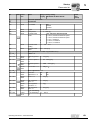
Important Notes................................................................................................... 5
1.1
Structure of the safety notes ....................................................................... 5
1.2
Rights to claim under warranty ................................................................... 5
1.3
Exclusion of liability..................................................................................... 5
Safety Notes ........................................................................................................ 6
2.1
General information .................................................................................... 6
2.2
Target group ............................................................................................... 6
2.3
Designated use ........................................................................................... 6
2.4
Transportation, storage ............................................................................... 7
2.5
Installation ................................................................................................... 7
2.6
Electrical connection ................................................................................... 8
2.7
Safe disconnection...................................................................................... 8
2.8
Operation .................................................................................................... 8
Unit Design .......................................................................................................... 9
3.1
Size 0XS / 0S / 0L....................................................................................... 9
3.2
Size 1 / 2S / 2............................................................................................ 10
3.3
Size 3 ........................................................................................................ 11
3.4
Size 4 / 5 ................................................................................................... 12
3.5
Unit designation / nameplate .................................................................... 13
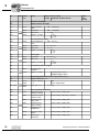
Installation ......................................................................................................... 14
4.1
Installation notes ....................................................................................... 14
4.2
Installing the optional power components ................................................. 19
4.3
UL compliant installation ........................................................................... 24
4.4
Scope of delivery and installation of loose items ...................................... 26
4.5
Installing cold plate ................................................................................... 31
4.6
Deactivating EMC capacitors (size 0 only) ............................................... 31
4.7
Wiring diagram .......................................................................................... 33
4.8
TF thermistor and TH bimetallic switch ..................................................... 34
4.9
Connecting braking resistors BW.. / BW..-T / BW..-P to X3 / X2 .............. 34
4.10 Connecting the brake rectifier ................................................................... 35
4.11 Installing FSC11B / FIO11B...................................................................... 36
4.12 Installing MBG11A speed control module ................................................. 41
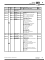
5
Startup................................................................................................................ 42
5.1
Brief description of the startup process..................................................... 42
5.2
General startup instructions ...................................................................... 43
5.3
Preliminary work and resources................................................................ 44
5.4
Optional keypad FBG11B ......................................................................... 45
5.5
Basic operation of the FBG11B keypad .................................................... 46
5.6
Manual operation with FBG11B speed control module............................. 48
5.7
External setpoint selection ........................................................................ 49
5.8
Startup using the FBG11B keypad ........................................................... 50
5.9
Startup with DBG60B................................................................................ 52
5.10 Startup with PC and MOVITOOLS® MotionStudio.................................... 59
Operating Instructions – MOVITRAC® B
3
5.11 Startup for MBG11A speed control module .............................................. 59
5.12 Starting up pumps and fans of non-SEW motors...................................... 60
5.13 Starting the motor ..................................................................................... 61
5.14 Parameter list............................................................................................ 65
6
7
8
9
Operation ........................................................................................................... 76
6.1
Data backup .............................................................................................. 76
6.2
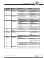
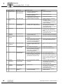
Return codes (r-19 ... r-38) ....................................................................... 77
6.3
Status displays.......................................................................................... 78
6.4
Unit status codes ...................................................................................... 79
6.5
DBG60B keypad ....................................................................................... 80
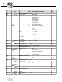
Service ............................................................................................................... 85
7.1
Unit information ......................................................................................... 85
7.2
List of faults (F-00 ... F-113)...................................................................... 87
7.3
SEW Electronics Service .......................................................................... 90
7.4
Extended storage...................................................................................... 91
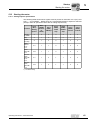
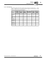
Technical Data................................................................................................... 92
8.1
CE marking, UL approval and C-Tick ....................................................... 92
8.2
General technical data .............................................................................. 93
8.3
MOVITRAC® B electronics data ............................................................... 95
8.4
Technical data of MOVITRAC® 07B ......................................................... 97
8.5
Front option FBG11B keypad ................................................................. 116
8.6
FSC11B communication module ........................................................... 117
8.7
FIO11B analog module ........................................................................... 118
Address List .................................................................................................... 119
Index................................................................................................................. 128
4
Operating Instructions – MOVITRAC® B
Important Notes
Structure of the safety notes
1
Important Notes
1.1
Structure of the safety notes
1
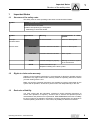
The safety notes in these operating instructions are structured as follows:
SIGNAL WORD!
Symbol
Nature and source of hazard.
Possible consequence(s) if disregarded.
•
Symbol
Example:
Measure(s) to avoid the hazard.
Signal word
Meaning
Consequences if disregarded
HAZARD!
Imminent hazard
Severe or fatal injuries
WARNING!
Possible hazardous situation
Severe or fatal injuries
CAUTION!
Possible hazardous situation
Minor injuries
STOP!
Possible damage to property
Damage to the drive system
or its environment
NOTE
Useful information or tip.
General hazard
Electric shock
Simplifies handling of the drive system.
1.2
Rights to claim under warranty
Adhering to the operating instructions is a prerequisite for fault-free operation and the
fulfillment of any right to claim under warranty. Read the operating instructions before
you start working with the unit.
Make sure that the operating instructions are available to persons responsible for the
system and its operation, as well as to persons who work independently on the unit.
1.3
Exclusion of liability
You must comply with the information contained in these operating instructions to
ensure safe operation of frequency inverters and to achieve the specified product
characteristics and performance requirements. SEW-EURODRIVE assumes no liability
for injury to persons or damage to equipment or property resulting from non-observance
of these operating instructions. In such cases, any liability for defects is excluded.
Operating Instructions – MOVITRAC® B
5
Safety Notes
General information
2
2
Safety Notes
The following basic safety notes are intended to prevent injury to persons and damage
to property. The operator must ensure that the basic safety notes are read and
observed. Make sure that persons responsible for the system and its operation, as well
as persons who work independently on the unit, have read through the operating
instructions carefully and understood them. If you are unclear about any of the information in this documentation, or if you require further information, please contact SEWEURODRIVE.
2.1
General information
Never install or start up damaged products. Submit a complaint to the shipping company
immediately in the event of damage.
During operation, drives with this type of enclosure may have live, uninsinuated, and
sometimes moving or rotating parts as well as hot surfaces.
Removing covers without authorization, improper use as well as incorrect installation or
operation may result in severe injuries to persons or damage to property.
Refer to the documentation for additional information.
2.2
Target group
Only a qualified electrician is authorized to transport, install, startup or service the
units (observe IEC 60364 or CENELEC HD 384 or DIN VDE 0100 and IEC 60664 or
DIN VDE 0110 as well as national accident prevention guidelines).
Qualified electricians in the context of these basic safety notes are persons familiar with
installation, assembly, startup and operation of the product who possess the required
qualifications.
Any activities regarding transportation, storage, operation, and disposal must be carried
out by persons who have been instructed appropriately.
2.3
Designated use
Frequency inverters are components intended for installation in electrical systems or
machines.
In case of installation in machines, startup of the drive inverters (meaning the start of
proper use) is prohibited until it is determined that the machine meets the requirements
stipulated in the EC Directive 98/37/EC (machine directive); observe EN 60204.
Startup (i.e. the start of designated use) is only permitted under observance of the EMC
(2004/108/EC) directive.
6
Operating Instructions – MOVITRAC® B
Safety Notes
Transportation, storage
2
The frequency inverters comply with the requirements of the Low Voltage Directive
2006/95/EC. The harmonized standards of the EN 61800-5-1/DIN VDE T105 series in
connection with EN 60439-1/VDE 0660 part 500 and EN 60146/VDE 0558 are applied
to these frequency inverters.
Technical data and information on the connection requirements are provided on the
nameplate and in the documentation; these must be observed under all circumstances.
2.3.1
Safety functions
Frequency inverters from SEW-EURODRIVE may not perform any safety functions
unless the inverters are subordinate to other safety systems. Use higher-level safety
systems to ensure protection of equipment and personnel.
When using the "Safe stop" function, you must observe the following publications:
2.4
•
MOVITRAC® B / Safe Disconnection – Conditions
•
MOVITRAC® B / Safe Disconnection – Applications
Transportation, storage
You must observe the notes on transportation, storage and proper handling. Observe
the climatic conditions as stated in the section "General technical data".
2.5
Installation
The units must be installed and cooled according to the regulations and specifications
in the corresponding documentation.
Protect the frequency inverters from excessive strain. Ensure that components are not
deformed and/or insulation spaces are maintained, particularly during transportation.
Avoid contact with electronic components and contacts.
Frequency inverters contain components that can easily be damaged by electrostatic
energy and improper handling. Prevent mechanical damage or destruction of electric
components (may pose health risk).
The following applications are prohibited unless the unit is explicitly designed for such
use:
•
Use in potentially explosive areas
•
Use in areas exposed to harmful oils, acids, gases, vapors, dust, radiation, etc.
•
Use in non-stationary applications which are subject to mechanical vibration and
impact loads in excess of the requirements in EN 61800-5-1.
Operating Instructions – MOVITRAC® B
7
Safety Notes
Electrical connection
2
2.6
Electrical connection
Observe the applicable national accident prevention guidelines when working on live
frequency inverters (e.g. BGV A3).
Electrical installation is to be carried out in compliance with pertinent regulations (e.g.
cable cross sections, fusing, protective conductor connection). Additional information is
contained in the documentation.
You will find notes on EMC-compliant installation, such as shielding, grounding, the
arrangement of filters and the routing of lines, in the documentation of the frequency
inverters. Always observe these instructions, even for frequency inverters bearing the
CE marking. The manufacturer of the system or machine is responsible for maintaining
the limits established by EMC legislation.
Protective measures and protection devices must comply with the regulations in force
(e.g. EN 60204 or EN 61800-5-1).
Required preventive measure: grounding the unit.
2.7
Safe disconnection
The unit meets all requirements for safe disconnection of power and electronic
connections in accordance with EN 61800-5-1. All connected circuits must also satisfy
the requirements for safe disconnection.
2.8
Operation
Systems with integrated frequency inverters must be equipped with additional
monitoring and protection devices, as applicable, according to the relevant safety guidelines and regulations, such as legislation governing technical equipment, accident prevention regulations, etc. Changes to frequency inverters using the operating software
are permitted.
Do not touch live components or power connections immediately after disconnecting the
frequency inverters from the supply voltage because there may still be some charged
capacitors. Note the respective labels on the frequency inverter.
Keep all covers and doors closed during operation.
The fact that the status LED and other display elements are no longer illuminated does
not indicate that the unit has been disconnected from the mains and no longer carries
any voltage.
Mechanical blocking or safety functions inside the unit may result in the motor coming
to a standstill. Eliminating the cause of the problem or performing a reset may result in
the drive re-starting automatically. If, for safety reasons, this is not permitted for the
driven machine, disconnect the unit from the mains before correcting the fault.
8
Operating Instructions – MOVITRAC® B
Unit Design
Size 0XS / 0S / 0L
3
Unit Design
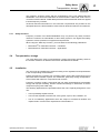
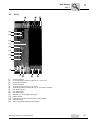
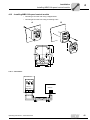
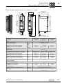
3.1
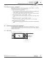
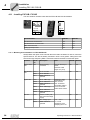
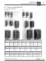
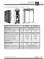
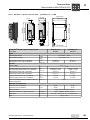
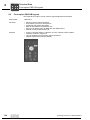
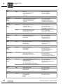
Size 0XS / 0S / 0L
3
[1]
[2]
[17]
[16]
[15]
[14]
[13]
[11]
[12]
[10]
[9]
[7]
[5]
[1]
[2]
[5]
[7]
[8]
[9]
[10]
[11]
[12]
[13]
[14]
[15]
[16]
[18]
PE connection
X1: Power supply connection:
3-phase: L1 / L2 / L3
1-phase: L / N
X2: Motor connection U / V / W / Brake connection +R / –R
Shield clamp, fixing strap below
X13: Binary outputs
X12: Binary inputs
X10: Analog input
Switch S11 for V-mA toggle analog input
(in sizes 0XS and 0S behind removable connector)
Option card slot (cannot be retrofitted / not for BG0XS)
Connection for optional communication / analog module
Optional keypad
Status LED (visible without optional keypad)
Fixing strap
Operating Instructions – MOVITRAC® B
9
Unit Design
Size 1 / 2S / 2
3
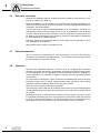
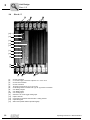
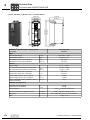
3.2
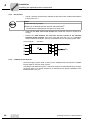
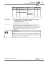
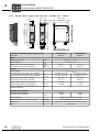
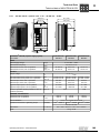
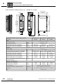
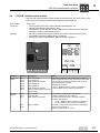
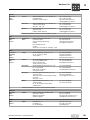
Size 1 / 2S / 2
[1]
[3]
[16]
[15]
[14]
[13]
[12]
[11]
[10]
[9]
[8]
[1]
[4]
[5]
[7]
[8]
[9]
[10]
[11]
[12]
[13]
[14]
[15]
10
X1: Power supply connection 3-phase: L1 / L2 / L3 / PE screw
X2: Motor connection U / V / W / PE screw
X3: Braking resistor connection R+ / R– / PE
Space for power shield clamp
X13: Binary outputs
X12: Binary inputs
X10: Analog input
Switch S11 for V-mA toggle analog input
Option card slot
Connection for optional communication / analog module
Optional keypad
Status LED (visible without optional keypad)
Operating Instructions – MOVITRAC® B
Unit Design
Size 3
3.3
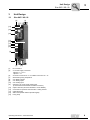
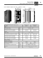
3
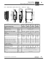
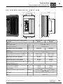
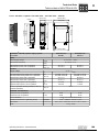
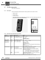
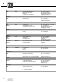
Size 3
[16]
[15]
[14]
[13]
[12]
[11]
[10]
[9]
[7]
[8]
[1]
[2]
[3]
[4]
[5]
[6]
[8]
[9]
[10]
[11]
[12]
[13]
[14]
[15]
X2: PE connection
X1: Power supply connection 3-phase: 1/L1 / 2/L2 / 3/L3
X4: DC link connection
X2: PE connection
X2: Motor connection U (4) / V (5) / W (6)
X3: Braking resistor connection R+ (8) / R– (9) and PE connection
X13: Binary outputs
X12: Binary inputs
X10: Analog input
Switch S11 for V-mA toggle analog input
Option card slot
Connection for optional communication / analog module
Optional keypad
Status LED (visible without optional keypad)
Operating Instructions – MOVITRAC® B
11
Unit Design
Size 4 / 5
3
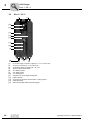
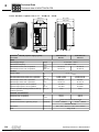
3.4
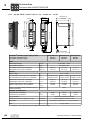
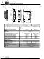
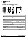
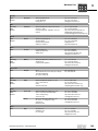
Size 4 / 5
[16]
[15]
[14]
[13]
[12]
[11]
[10]
[9]
[7]
[8]
[4]
[1]
[2]
[3]
[4]
[5]
[6]
[8]
[9]
[10]
[11]
[12]
[13]
[14]
[15]
12
[5]
[6]
X2: PE connection
X1: Power supply connection 3-phase: 1/L1 / 2/L2 / 3/L3
X4: DC link connection
X2: PE connection
X2: Motor connection U (4) / V (5) / W (6)
X3: Braking resistor connection R+ (8) / R– (9) and PE connection
X13: Binary outputs
X12: Binary inputs
X10: Analog input
Switch S11 for V-mA toggle analog input
Option card slot
Connection for optional communication / analog module
Optional keypad
Status LED (visible without optional keypad)
Operating Instructions – MOVITRAC® B
Unit Design
Unit designation / nameplate
3.5
3
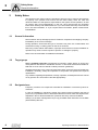
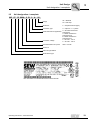
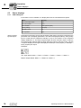
Unit designation / nameplate
MC 07
B 0004- 2 B 1- 4-
00
Design
00 = Standard
S0 = Safe stop
Quadrants
4 = 4Q (with brake chopper)
Connection type
3 = 3-phase / 1 = 1-phase
0 = No radio interference
Radio interference suppression suppression
A = Radio interference
suppression C2
B = Radio interference
suppression C1
2 = AC 200 ... 240 V
Connection voltage
5 = AC 380 ... 500 V
Recommended motor power
0022 = 2.2 kW
Version B
Series and generation
MOVITRAC® type
The unit status is indicated above the lower barcode.
Operating Instructions – MOVITRAC® B
13
Installation
Installation notes
4
4
Installation
4.1
Installation notes
NOTE
Comply with the safety notes during installation.
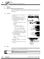
4.1.1
Mounting the front options
[1]
[A]
[2]
[3]
[1]
[4]
[B]
[2]
[1]
[C]
[2]
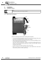
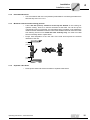
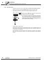
Observe the following sequence when mounting the front options:
•
To mount the FBG11B [A] keypad, first insert it on top of the housing [1]. Next, press
the socket on the keypad onto the connector of the unit [2].
•
When using the FSC11B communication module or the FIO11B module [B], you have
to mount the spacer bolt [1] first for size 0.
Insert the FSC11B communication module or the FIO11B module [B] first at the
bottom of the housing [2] before pressing the socket of the front option onto the
connector of the unit [3].
Finally secure the front option using the screw on the unit [4].
•
14
Before mounting the cover [C] at its final position, place it about 5 mm in front of the
final position [1] and then slide it upwards [2].
Operating Instructions – MOVITRAC® B
Installation
Installation notes
4.1.2
Recommended tools
•
4.1.3
4
Use a screwdriver with a 2.5 mm (0.098 in) wide blade for connecting the electronics
terminal strip X10 / X12 / X13.
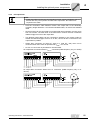
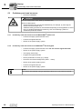
Minimum clearance and mounting position
•
Leave 100 mm (3.94 in) clearance at the top and bottom of the housing for
optimum cooling. There is no need for clearance at the sides. You can line up the
units directly next to one another. It is important that air circulation is not impeded by
cables and other installation material. Prevent the heated exhaust air from other units
from blowing onto this unit. Install the units vertically only. You must not install
them horizontally, tilted or upside down.
•
Proper heat dissipation of the rear side of the heat sink improves the thermal
utilization of the unit.
100 mm
(3.94 in)
100 mm
(3.94 in)
4.1.4
Separate cable ducts
•
Route power leads and electronics leads in separate cable ducts.
Operating Instructions – MOVITRAC® B
15
Installation
Installation notes
4
4.1.5
4.1.6
4.1.7
4.1.8
EMC-compliant installation
•
All cables except for the supply system lead must be shielded. For the motor cable,
you can use the HD.. option (output choke) instead of the shielding to meet the
interference emission limit values .
•
When using shielded motor cables, e.g. prefabricated motor cables from SEWEURODRIVE, you must keep the unshielded conductors between the shield and
connection terminal of the inverter as short as possible.
•
Apply the shield by the shortest possible route and make sure it is grounded
over a wide area at both ends. If using double-shielded cables, ground the outer
shield on the inverter end and the inner shield at the other end.
•
You can also use earthed sheet-metal ducts or metal pipes to shield the cables.
Route the power and control cables separately.
•
Provide high frequency compatible grounding for the inverter and all additional
units (wide area metal-on-metal contact between the unit housing and ground, e.g.
unpainted control cabinet mounting panel).
•
SEW recommends using earth-leakage monitors with a pulse code measuring
process in voltage supply systems with a non-earthed star point (IT systems).
Use of such devices prevents the earth-leakage monitor mis-tripping due to the earth
capacitance of the inverter.
•
For size 0, SEW recommends deactivating the interference suppressor filter using
the enclosed insulation discs (see Deactivating EMC capacitors (size 0 only)).
•
Only use contactors in utilization category AC-3 (EN 60947-4-1).
IT systems
Contactor
Cross sections
•
Supply system lead: Cross section according to rated input current Imains at rated
load.
Motor lead: Cross section according to rated output current IN
Electronics cables:
Maximum 1.5 mm2 (AWG16) without conductor end sleeves1)
Maximum 1.0 mm2 (AWG17) with conductor end sleeves
1) Fine wired cables may not be installed without conductor end sleeves.
16
Operating Instructions – MOVITRAC® B
Installation
Installation notes
4.1.9
4
Cable lengths for individual drives
•
The cable lengths depend on the PWM frequency. The permitted motor cable lengths
are listed in the "Project Planning" section of the MOVITRAC® B system manual.
•
Only connect an ohmic/inductive load (motor), do not connect a capacitive load!
4.1.10 Unit output
4.1.11 Braking resistor connection
•
Cut the lines to the required length.
•
Use 2 tightly twisted leads or a 2-core shielded power cable. Cross-section
according to the rated output current of the inverter.
•
Protect the braking resistor with a bimetallic relay with trip class 10 or 10A (wiring
diagram). Set the trip current according to the technical data of the braking
resistor.
•
For BW..-T braking resistors, you can connect the integrated thermostat using
a 2-core, shielded cable as an alternative to a bimetallic relay.
•
Flat-type braking resistors have internal thermal overload protection (fuse which
cannot be replaced). Install the flat-type braking resistors together with the
appropriate touch guard.
4.1.12 Installing the braking resistor
•
The supply cables to the braking resistors carry a high voltage (approx. DC 900 V)
during rated operation.
•
The surfaces of the braking resistors get very hot when the braking resistors are
loaded with Prated. Choose a suitable installation location. Braking resistors are
usually mounted on the control cabinet roof.
4.1.13 Binary outputs
•
The binary outputs are short-circuit proof and protected against external
voltage to 30 V. Higher external voltages can destroy the binary outputs.
4.1.14 Interference emission
•
Use shielded motor cables or HD output chokes for EMC compliant installation.
Operating Instructions – MOVITRAC® B
17
4
Installation
Installation notes
4.1.15 Switched inductances
NOTE
The minimum distance of switched inductances to the inverter must be at least
150 mm (5.91 in).
•
Use suppressors to suppress interference on
– contactors
– relays
– solenoid valves
Suppressors are, for example, diodes, varistors, or RC elements:
Do not connect any suppressors directly on MOVITRAC® B. Connect suppressors as
closely as possible to the inductance.
4.1.16 Line filters
MOVITRAC® B frequency inverters have an integrated line filter as standard. They
comply with the following limit value class to EN 55011 on the line side without further
measures:
•
Single-phase connection: C1 cable conducted
•
Three-phase connection: C2
No EMC limits are specified for interference emission in voltage suply systems without
an earthed star point (IT system). The efficiency of line filters is severely limited.
4.1.17 Line protection and earth-leakage circuit breaker
•
Install the fuses at the beginning of the mains cable behind the supply bus
junction (→ Basic unit wiring diagram).
•
SEW-EURODRIVE recommends that you do not use earth-leakage circuit breakers.
However, if an earth-leakage circuit breaker is stipulated for direct or indirect protection against contact, observe the following note in accordance with EN 61800-5-1:
WARNING!
Wrong type of earth-leakage circuit breaker installed.
Severe or fatal injuries.
MOVITRAC® can cause direct current in the protective earth. In cases where an earthleakage circuit breaker is used for protection against direct or indirect contact, only
install a type B earth-leakage circuit breaker on the power supply end of the
MOVITRAC® unit.
18
Operating Instructions – MOVITRAC® B
Installation
Installing the optional power components
4
4.1.18 PE mains connection (→ EN 61800-5-1)
Earth-leakage currents ≥ 3.5 mA may occur during normal operation. To meet the
requirements of EN 61800-5-1 observe the following:
•
Supply system lead < 10 mm2 (AWG7):
– Route a second PE conductor with the same cross section as the supply system
lead in parallel to the protective earth via separate terminals, or
– use a copper protective earth conductor with a cross section of 10 mm2 (AWG7)
•
Supply system lead 10 mm2 ... 16 mm2 (AWG7 ... AWG5):
– Copper protective earth conductor with the cross section of the supply system
lead.
•
Supply system lead 16 mm2 ... 35 mm2 (AWG5 ... AWG2):
– Copper protective earth conductor with a cross section of 16 mm2 (AWG5)
•
Supply system lead > 35 mm2 (AWG2):
– Copper protective earth conductor with half the cross section of the supply system
lead.
4.2
Installing the optional power components
When more than five 3-phase units or more than one 1-phase unit are connected to
a supply system contactor designed for the total current: Connect a line choke for
limiting the inrush current.
4.2.1
ND line choke
ND ... series line choke connection
B
Operating Instructions – MOVITRAC® B
19
Installation
Installing the optional power components
4
4.2.2
NF line filter
The NF.. line filter can be used to maintain the limit value class C1/B for MOVITRAC®
B units sizes 0 to 4.
•
STOP!
Possible damage to property
Switching is not allowed between line filter and MOVITRAC®.
•
Consequences if disregarded: Damage to the input level.
•
Install the line filter close to the inverter but outside the minimum clearance for
cooling.
•
Restrict the cable between the line filter and the inverter to the absolute
minimum length required, and never more than 400 mm (15.7 in). Unshielded,
twisted cables are sufficient. Also use unshielded lines for the supply system lead.
Connecting NF...-... line filters
B
4.2.3
Foldable ferrites ULF11A
Place the supply system cable (L and N) in the foldable ferrite and press the foldable
ferrites together until they snap in place.
Compliance with EMC limit class C1 has been tested on a specified test setup. Compliance with class C1 for signal interference is achieved by the proper installation of the
foldable ferrites ULF11A.
20
Operating Instructions – MOVITRAC® B
Installation
Installing the optional power components
4.2.4
4
HF output filter
NOTE
•
Install output filters next to the corresponding inverter. Leave a ventilation space of
at least 100 mm (3.94 in) below and above the output filter. No clearance is
required on the sides.
•
Limit the connection cable between inverter and output filter to the absolutely
necessary length. Maximum 1 m/3 ft with unshielded cable, 10 m/33 ft with shielded
cable.
•
Several motors can be connected to one output filter when operating a motor group
from one inverter. The total value of the rated motor currents must not exceed the
rated throughput current of the output filter.
•
Two identical output filters can be connected in parallel to one inverter output to
double the rated throughput current. To do this, connect all like connections to the
output filters in parallel.
•
Output filter connection V5 (with HF...-503) or 7 (with HF...-403) must not be
connected when the inverter is operated with fPWM = 4 or 8 kHz.
•
No VDC link connection is permitted for unit sizes 0XS.
HF output filter connection without VDC link connection (PWM frequency only 4 or 8 kHz)
B
X1
X2/3
+R
HF output filter connection without VDC link connection (PWM frequency only 12 or
16 kHz)
B
X1
X2/3
+R
Operating Instructions – MOVITRAC® B
21
Installation
Installing the optional power components
4
4.2.5
HD output choke
•
Install the output choke close to MOVITRAC® B outside the minimum clearance.
•
Always route all three phases (not PE) together through the output choke.
•
If the cable is shielded, do not route the shield through the output choke.
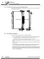
4
U
n=5
•
5
V
6
댷
W
PE
When using the HD output choke, the cable must be
wrapped around the choke 5 times.
Only 5 loops are possible if the cable has a large diameter. To make up for this, 2 or 3 output chokes should be
connected in series. SEW recommends connecting in
series 2 output chokes in case of 4 windings and 3 output chokes in case of 3 windings.
Installing HD012 output choke:
Install output choke under the corresponding inverter. Leave a ventilation space of at
least 100 mm (3.94 in) below and above the output choke. Provide a clearance of
10 mm (0.39 in) on each side.
Three alternative connection options are provided for connecting the protective
earth. You can connect the PE line of the motor cable directly on the frequency
inverter.
22
Operating Instructions – MOVITRAC® B
Installation
Installing the optional power components
4.2.6
4
FKE12B / FKE13B EMC-modules
Use the supplied screws to mount the EMC module together with the MOVITRAC® B
frequency inverter onto the conductive mounting surface in the control cabinet.
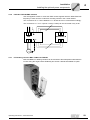
The connections U / V / W are labeled U / V / W and have to be connected accordingly.
The connections L1 / L2 / L3 (brown / orange / white) can be connected in any order.
L1 L2 L3
PE
L1 L2 L3
MOVITRAC® B
FKE
PE
U V W
U V W
M
3
4.2.7
~
PTC braking resistors BW1 / BW3 with FKB10B
BW1 and BW3 PTC braking resistors can be mounted to the shield plate underneath the
inverter using the angle bracket FDB10B, part number 18216218 available as option.
Operating Instructions – MOVITRAC® B
23
Installation
UL compliant installation
4
4.2.8
Flat-design resistors with FKB11/12/13B and FHS11/12/13B
Flat-design resistors can be mounted between inverter and control cabinet with FKB11/
12/13B or FHS11/12/13B.
FKB11/12/13B
4.3
FHS11/12/13B
UL compliant installation
Please note the following points for UL compliant installation:
•
Use only copper cables with the following temperature ranges as connection cables:
– MOVITRAC® B 0003 ... 0300: temperature range 60/75 °C (140/167 °F)
– MOVITRAC® B 0370 and 0450: temperature range 75 °C (167 °F)
24
•
Necessary tightening torques of MOVITRAC® B power terminals: See installation
notes.
•
Operate the inverters on supply systems with a maximum phase-to-earth voltage of
AC 300 V only.
•
The inverter can only be operated on IT systems if the phase-to-earth voltage of
AC 300 V cannot be exceeded either during operation or in case of an error.
•
MOVITRAC® B frequency inverters are only allowed to be operated on supply
systems which can supply maximum values in accordance with the following table.
Only use melting fuses. The performance data of the fuses must not exceed the
values in the following table.
Operating Instructions – MOVITRAC® B
Installation
UL compliant installation
4.3.1
4
Maximum values/fuses
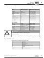
The following maximum values/fuses must be observed for UL compliant installation:
230 V units / 1-phase
Max. supply current
Max. supply voltage
Fuses
0003 / 0004 / 0005 / 0008
AC 5000 A
AC 240 V
15 A / 250 V
0011 / 0015 / 0022
AC 5000 A
AC 240 V
30 A / 250 V
230 V units / 3-phase
Max. mains current
Max. mains voltage
Fuses
0003 / 0004 / 0005 / 0008
AC 5000 A
AC 240 V
15 A / 250 V
0011 / 0015 / 0022
AC 5000 A
AC 240 V
20 A / 250 V
0037
AC 5000 A
AC 240 V
30 A / 250 V
0055 / 0075
AC 5000 A
AC 240 V
110 A / 250 V
0110
AC 5000 A
AC 240 V
175 A / 250 V
0150
AC 5000 A
AC 240 V
225 A / 250 V
0220 / 0300
AC 10000 A
AC 240 V
350 A / 250 V
400/500 V units
Max. mains current
Max. mains voltage
Fuses
0003 / 0004 / 0005 / 0008 /
0011 / 0015
AC 5000 A
AC 500 V
15 A / 600 V
0022 / 0030 / 0040
AC 5000 A
AC 500 V
20 A / 600 V
0055 / 0075
AC 5000 A
AC 500 V
60 A / 600 V
0110
AC 5000 A
AC 500 V
110 A / 600 V
0150 / 0220
AC 5000 A
AC 500 V
175 A / 600 V
0300
AC 5000 A
AC 500 V
225 A / 600 V
0370 / 0450
AC 10000 A
AC 500 V
350 A / 600 V
0550 / 0750
AC 10000 A
AC 500 V
500 A / 600 V
NOTES
•
•
Only use tested units with a limited output voltage (Vmax = DC 30 V) and limited
output current (I ≤ 8 A) as an external DC 24 V voltage source.
UL certification does not apply to operation in voltage supply systems with a
non-grounded star point (IT systems).
Operating Instructions – MOVITRAC® B
25
Installation
Scope of delivery and installation of loose items
4
4.4
Scope of delivery and installation of loose items
4.4.1
Scope of delivery of loose items
The scope of delivery includes a bag for loose items. Its contents depends on the
inverter size.
Scope of delivery of loose items for size
0XS / 0S / 0L
1
2S
•
•
Shield plate for control electronics with clamps and screws [1]
3 connectors for electronics terminals [2]
•
Grounding terminals with screws [4]
•
Shield plate for the power section
with clamps and screws [3]
Connector for mains (2 or 3-pole)
and motor [5]
Plastic insulations with stickers [6]
•
•
•
Shield plate for
the power section
without screws
•
Fixing straps
•
•
2
Touch guard
Shield plate for the
power section with
screws
–
3
4/5
–
–
–
–
–
•
Touch guard
Loose items for size 0:
X1
[4]
[5]
X2
X10
[2]
X12
X13
[1]
M4×20
2 × M4×20
7 × M4×10
[6]
EMV-Kondensatoren deaktiviert.
EMC Capacitors deactivated.
Condensateurs CEM désactivés.
[3]
8196737.LBL
26
Operating Instructions – MOVITRAC® B
Installation
Scope of delivery and installation of loose items
4.4.2
4
Installing shield plate for control electronics (all sizes)
MOVITRAC® B includes a shield plate for the control electronics with a retaining screw as standard. Install the shield plate for
control electronics as follows:
1. Loosen the screw first [1].
2. Push the shield clamp through the slot in the plastic housing.
3. Fasten the shield clamp.
[1]
4.4.3
Size 0
Power shield clamp
A power shield plate for the power section with 2 retaining screws is supplied as
standard with MOVITRAC® size 0. Mount the shield plate for the power section using
the two retaining screws.
[1]
[2]
[1] PE connection
Operating Instructions – MOVITRAC® B
[2] Shield plate
27
Installation
Scope of delivery and installation of loose items
4
Size 1
SEW-EURODRIVE supplies a shield plate for the power section as standard with
MOVITRAC® B size 1. Mount the shield plate for the power section using the unit's two
retaining screws.
[1]
[2]
[1] Shield clamp
Sizes 2S / 2
[2] PE connection
SEW-EURODRIVE supplies a shield plate for the power section with two retaining
screws as standard with MOVITRAC® B sizes 2S / 2. Mount the shield plate for the
power section using the two retaining screws. The illustration shows size 2.
[1] Shield clamp
[2] PE connection
The shield plate for the power section provides you with a very convenient way of
installing the shield for the motor and brake cables. Apply the shield and PE conductor
as shown in the illustrations.
Sizes 3 ... 5
28
With MOVITRAC® B sizes 3 ... 5, no shield plates are supplied for the power section.
Use commercially available shield clamps for installing the shielding of motor and brake
cables. Apply the shield as closely as possible to the inverter.
Operating Instructions – MOVITRAC® B
Installation
Scope of delivery and installation of loose items
4.4.4
4
Installing the touch guard
HAZARD
Uncovered power connections.
Severe or fatal injuries from electric shock.
•
•
Size 2S
Install the touch guard according to the regulations.
Never start the unit if the touch guard is not installed.
SEW-EURODRIVE supplies two touch guards for the DC link and braking resistor terminals as standard with MOVITRAC® B size 2S. Without touch guard, MOVITRAC® B
size 2S has degree of protection IP10. When the touch guard is installed, the unit has
degree of protection IP20.
IP10
X4
-UZ +UZ PE
IP20
X4
-UZ +UZ PE
IP10
X3
8/+R 9/-R PE
IP20
X3
8/+R 9/-R PE
Operating Instructions – MOVITRAC® B
29
Installation
Scope of delivery and installation of loose items
4
Sizes 4 / 5
Two touch guards with 8 retaining screws are supplied as standard with MOVITRAC®
sizes 4 / 5. Install the touch guard on both covers of the power section terminals.
Touch guard for MOVITRAC® B sizes 4 / 5:
[2]
[1]
[3]
The touch guard comprises the following parts:
[1] Cover
[2] Connection plate
[3] Screen (only for size 4)
The MOVITRAC® B unit sizes 4 / 5 can only achieve degree of protection IP10 when the
following conditions are met:
•
Touch guard is fully installed
•
The shrink tubing is installed on all power terminals (X1, X2, X3, X4)
NOTE
If the above conditions are not met, MOVITRAC® units sizes 4 and 5 have degree of
protection IP00.
30
Operating Instructions – MOVITRAC® B
Installation
Installing cold plate
4.5
4
Installing cold plate
The dissipation of the frequency inverter power loss can take place via coolers that work
with different cooling media (air, water, oil, etc.). This can be useful, for example, in restricted installation spaces. When adhering to the usual installation notes (40 °C
(104 °F) / 100 mm (3.94 in) space above and below), cold-plate technology is not
necessary.
A good thermal connection to the cooler is important for safe operation of frequency
inverters:
4.6
•
The contact area between cooler and frequency inverter has to be the size of the
frequency inverter cooling plate.
•
Level contact surface, deviation max. up to 0.05 mm (0.0002 in).
•
Connect cooler and cooling plate with all necessary screw connections.
•
The mounting plate must not exceed 70 °C (158 °F) during operation. This must be
ensured by the cooling medium.
•
Cold plate installation is not possible with FHS or FKB.
Deactivating EMC capacitors (size 0 only)
Only electricians are allowed to convert the unit. Once converted, the unit must be
marked with the sticker provided in the accessory bag.
HAZARD
Severe or fatal injuries from electric shock.
•
•
•
•
•
Disconnect the inverter from the power. Switch off the DC 24 V and the mains
voltage.
Wait 10 seconds.
Ensure that the unit is de-energized.
Take appropriate measures to avoid electrostatic charges (use discharge strap,
conductive shoes, etc.) before removing the cover.
Touch only the unit frame and heat sink. Do not touch any electronic components.
Proceed as follows to deactivate the EMC capacitors for MOVITRAC® B:
1. Open the unit:
– Remove all connectors.
– Remove the electronics shield clamp.
– Remove the housing retaining screw in the center of the housing front.
– Remove the housing.
Operating Instructions – MOVITRAC® B
31
4
Installation
Deactivating EMC capacitors (size 0 only)
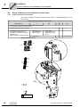
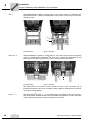
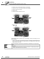
2. Remove the two screws [A] securing the circuit board.
3. Install the screws in the plastic insulations provided [B].
4. Fasten screws to the unit [C].
5. Close the unit.
6. Attach the sticker provided to the unit.
[A]
[A]
[B]
[C]
[C]
Deactivating the EMC capacitors stops earth-leakage currents from flowing over the
EMC capacitors.
•
Please ensure that the earth-leakage currents are essentially only determined by the
level of the DC link voltage, the PWM frequency, the applied motor cable and its
length and the motor used.
When the suppression capacitors are deactivated, the EMC filter is no longer active.
NOTE
IT systems
•
32
No EMC limits are specified for interference emission in voltage supply systems
without a grounded star point (IT systems).
Operating Instructions – MOVITRAC® B
Installation
Wiring diagram
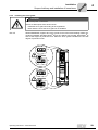
4.7
4
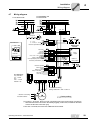
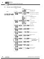
Wiring diagram
3 x AC 400/500 V / PE
3 x AC 230 V / PE
1 x AC 230 V / N / PE
[1]
–UZ +UZ
PE
7
8
PE X4
Changeover
REF1
MOVITRAC® B
S1
0 ... 10 V*
0 ... 20 mA; 4 ... 20 mA
Reference potential analog signals
Higher-level
control
S2
ON
ON
OFF
OFF
Binary input
Fault reset
CW/stop
CCW stop
Enable/stop*
FSC11B
n13 = n11 + n12
X46
HL ⊥ 1 2 3 4 5 6 7
X17 "Safe stop"
only with 400 V
5.5 ... 75 kW
and
0.55 ... 4.0 kW
MC07B...-S0
Supply voltage for
+24V input/output (can be disabled)
Reference potential binary signals
X17:
Reference
binary outputs
24VIO
Reference potential
Brake released*
Ready
Reference potential
Relay contact/fault
NOC relay
NCC relay
1 DGND
2 VO24
3 SOV24
4 SVI24
X45
Binary
outputs
}
X44
PE
PE X2
X3
[1]
[1]
→ Section "Connecting
braking resistor BW.. / BW..-T / BW..-P"
→ Section "Connecting
the brake rectifier"
3-phase
Factory setting
[1] In sizes 1, 2S, and 2, there is no PE connection next to the power supply connection
terminals and motor connection terminals [X1]/[X2]. In this case, use the PE terminal
next to the DC link connection [X4].
From size 3 onwards, there are two additional PE terminals.
Operating Instructions – MOVITRAC® B
33
Installation
TF thermistor and TH bimetallic switch
4
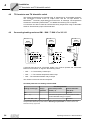
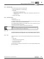
4.8
TF thermistor and TH bimetallic switch
The winding temperature is monitored using TF thermistors or TH bimetallic switches.
The connection is made at the TF output VOTF and the TF input DI05TF of
MOVITRAC®. The binary input DI05TF must be set to TF message. The temperature
will then be monitored by MOVITRAC®; no additional monitoring unit is required.
A connection can also be made to 24VIO and a binary output when using TH bimetallic
switches. Set the binary input to /External fault.
4.9
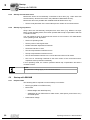
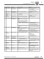
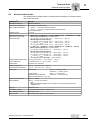
Connecting braking resistors BW.. / BW..-T / BW..-P to X3 / X2
X2/X3:
+R -R PE
X2/X3:
X2/X3:
+R -R PE
+R -R PE
8
8
9
9
F16
→ K11
BW...-...-P
BW...-...-T
95
97
F16
→ K11
96
98
4
T2
RB1
→ K11
T1
6
BW...
RB2
A terminal must be set to "/Controller inhibit". K11 must be opened and "/Controller
inhibit" must receive a "0" signal in the following cases:
•
BW...-...-P: The auxiliary contact trips
•
BW...-...-T: The internal temperature switch trips
•
BW...: The external bimetallic relay F16 trips
The resistor circuit must not be interrupted.
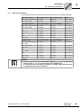
Overload protection for braking resistors BW:
Overload protection
Braking resistor type
Design
specified
Internal temperature
switch (..T)
External bimetallic
relay (F16)
BW...
–
–
Required
–
One of the two options (internal temperature switch /
external bimetallic relay) is required.
Adequate
–
BW...-...-T
1)
BW...-003 / BW...-005
Permitted
1) Permitted mounting options: On horizontal or vertical surfaces with brackets at the bottom
and perforated sheets at top and bottom. Mounting not permitted: On vertical surfaces with
brackets at the top, right or left.
34
Operating Instructions – MOVITRAC® B
Installation
Connecting the brake rectifier
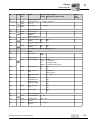
4.10
4
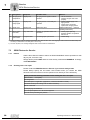
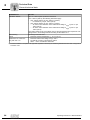
Connecting the brake rectifier
NOTE
The connection of the brake rectifier requires a separate supply system cable; supply
from the motor voltage is not permitted!
Use contactors of utilization category AC-3 for K11 and K12 only.
Always switch off the brake on the DC and AC sides in:
•
All hoist applications.
•
Drives which require a rapid brake response time.
If the brake rectifier is installed in the control cabinet, route the connecting leads
between the brake rectifier and the brake separately from other power cables. Routing
together with other cables is only permitted if the other cables are shielded.
Wiring diagrams
DOØ2
GND
Cut-off in the
AC and DC circuits
Cut-off in the
AC and DC circuits
Cut-off in the
AC circuit
Note the corresponding connection regulations for brakes without BG/BGE or BME.
Refer to the SEW publication "Drive Engineering - Practical Implementation: SEW disk
brakes" for detailed information about this topic .
Operating Instructions – MOVITRAC® B
35
Installation
Installing FSC11B / FIO11B
4
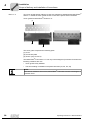
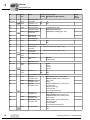
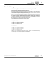
4.11
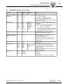
Installing FSC11B / FIO11B
You can enhance the basic units with the FSC11B and FIO11B modules.
S1
S2
ON
OFF
X44
X44
FSC11B
FIO11B
X46
X45 X40
X45
HL ⊥ 1 2 3 4 5 6 7
HL ⊥ 1 2 3 4 5
Connection/unit
FIO11B
FSC11B
RS-485 service interface X44
Yes
Yes
RS-485 terminal connection X45
Yes
Yes
SBus connection X46
No
Yes
Analog input/output X40
Yes
No
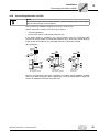
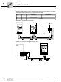
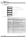
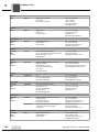
4.11.1 Mounting and installation on FSC11B/FIO11B
Always attach the option to the unit with the screw that is included. For size 0, mount the
spacer bolt first. The bolt is already mounted in sizes 1 and greater. Fitting the screw
secures the high-frequency EMC connection between the basic unit and the option.
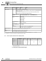
Function
Description
Data
FSC11B
FIO11B
Service inter- X44
face
Via RJ10 plug
connector
Only for service purposes
Maximum cable
length 3 m (10 ft)
Yes
Yes
RS-485 inter- X45:H
face
X45:L
ST11: RS-485+
Yes
Yes
Yes
No
Yes
No
No
Yes
System bus
36
Terminal
ST12: RS-485–
X45:⊥
GND: Reference
potential
X46:1
SC11: SBus high
X46:2
SC12: SBus low
X46:3
GND: Reference
potential
X46:4
SC21: SBus high
X46:5
SC22: SBus low
X46:6
GND: Reference
potential
DC 24 V
X46:7
24VIO: Auxiliary voltage / external voltage
supply
Analog input
X40:1
AI2: Voltage input
X40:2
GND: Reference
potential
CAN bus to CAN
specification 2.0,
parts A and B
Max. 64 stations
Terminating resistor
120 Ω can be activated via DIP switch
–10 ... +10 V
Ri > 40 kΩ
Resolution 10 bit
Sampling time 5 ms
Operating Instructions – MOVITRAC® B
Installation
Installing FSC11B / FIO11B
4
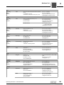
Function
Terminal
Description
Data
FSC11B
FIO11B
Analog output
X40:3
GND: Reference
potential
No
Yes
X40:4
AOV1: Voltage output
X40:5
AOI1: Current output
0 ... +10 V
Imax = 2 mA
0 (4) ... 20 mA
Resolution 10 bit
Sampling time 5 ms
Short-circuit proof,
protected against
external voltage up to
30 V
The DC 24 V function of X46:7 is identical to X12:8 of the basic unit. All GND terminals
of the unit are connected to each other and to PE.
Cable specification
•
Use a 4-core twisted and shielded copper cable (data transmission cable with braided
copper shield). The cable must meet the following specifications:
– Core cross section 0.25 ... 0.75 mm2 (AWG 23 ... AWG 18)
– Line resistance 120 Ω at 1 MHz
– Capacitance per unit length ≤ 40 pF/m at 1 kHz
Suitable cables include CAN bus or DeviceNet cables.
Connecting shield
•
•
•
Connect the shield to the electronics shield clamp on the inverter or master controller and
make sure it is connected over a wide area at both ends.
There is no need for a ground connections between MOVITRAC® B and gateways, or
MOVITRAC® B and MOVITRAC® B with shielded cables. A 2-core cable is permitted in this
case.
When connecting MOVIDRIVE® B and MOVITRAC® B always make sure that the electrical
isolation between the reference potential DGND and ground is neutralized in
MOVIDRIVE® B.
STOP!
Potential displacement
Possible consequences include malfunctions that could lead to irreparable damage to
the unit.
•
There must not be any potential displacement between the connected units. Take
appropriate measures to avoid potential displacement, such as connecting the
unit ground connectors using a separate cable.
Operating Instructions – MOVITRAC® B
37
4
Installation
Installing FSC11B / FIO11B
4.11.2 Installing system bus (SBus) to FSC11B
Max. 64 CAN bus stations can be addressed using the system bus (SBus). The SBus
supports transmission technology compliant with ISO 11898.
S1
S2
SC11/SC12
SC21/SC22
off
off
CAN1
CAN1
on
off
CAN1 concluded
–
X
On
MOVITRAC®
®
MOVITRAC B
Reserved
B system bus connection
®
®
MOVITRAC B
MOVIDRIVE B
S12
S1
S2
ON
ON
OFF
X44
FSC11B
X46
HL ⊥ 1 2 3 4 5 6 7
ON OFF
S2
OFF
X44
X45
S1
X12:
DGND 1
SC11 2
FSC11B
X45
SC12 3
X46
HL ⊥ 1 2 3 4 5 6 7
System bus connection MOVITRAC®B with UFx
MOVITRAC® B
UFx
S1
S2
ON
X44
OFF
FSC11B
X45
X46
HL ⊥ 1 2 3 4 5 6 7
38
Operating Instructions – MOVITRAC® B
Installation
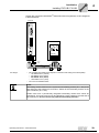
Installing FSC11B / FIO11B
4
System bus connection MOVITRAC® B with DFx/UOH11B gateways or DFx integrated
in MOVITRAC® B
UOH11B
DFP21B
RUN
BUS
FAULT
9
5
6
1
X30
20
21
22
23
0 1
24
25
26
AS
ADDRESS
®
MOVITRAC B
S1
S2
ON
H1
H2
X44
OFF
X24
FSC11B
X45
X26
X46
HL ⊥ 1 2 3 4 5 6 7
1234567
+ 24 V
GND
Line length
•
The permitted total cable length depends on the baud rate setting of the SBus (P884):
– 125 kBaud:320 m (1050 ft)
– 250 kBaud: 160 m (525 ft)
– 500 kBaud: 80 m (260 ft)
– 1000 kBaud: 40 m (130 ft)
•
You must use shielded cables.
NOTE
Terminating resistor: Switch on the system bus terminating resistor (S1 = ON) at the
start and end of the system bus connection. Switch off the terminating resistor on the
units in between (S1 = OFF).
Certain units have a permanently integrated terminating resistor that cannot be
switched off. This is the case for UFx and DFx/UOH. These gateways form the end of
the physical line. Do not connect any external terminating resistors.
Operating Instructions – MOVITRAC® B
39
Installation
Installing FSC11B / FIO11B
4
4.11.3 Installing RS-485 interface to FSC11B
The RS-485 interface can be used for connecting max. 32 MOVITRAC® units or 31
MOVITRAC® units and a higher-level controller (PLC).
MOVITRAC® B RS-485 connection
MOVITRAC® B
MOVITRAC® B
X44
•
•
DGND 9
ST11 10
FSC11B /
FIO11B
X46
X45
HL ⊥ 1 2 3 4 5 6 7
Cable length
X13
X44
FSC11B /
FIO11B
X45
MOVIDRIVE® B
ST12 11
X46
HL ⊥ 1 2 3 4 5 6 7
The permitted total cable length is 200 m.
You must use shielded cables.
NOTE
Terminating resistor: Dynamic terminating resistors are installed. Do not connect any
external terminating resistors.
4.11.4 Wiring analog module FIO11B
Bipolar analog input Unipolar
AI2
input AI2
RS-485+
RS-485–
GND
AI2
GND
GND
AOV1
AOC1
RS-485+
RS-485–
GND
AI2
GND
GND
AOV1
AOC1
X45 X40
HL ⊥ 1 2 3 4 5
HL ⊥ 1 2 3 4 5
HL ⊥ 1 2 3 4 5
HL ⊥ 1 2 3 4 5
GND
A
GND
–10 V
external
40
X45 X40
RS-485+
RS-485–
GND
AI2
GND
GND
AOV1
AOC1
X45 X40
RS-485+
RS-485–
GND
AI2
GND
GND
AOV1
AOC1
X45 X40
analog Current analog out- Voltage analog output AOC1
put AOV1
+10 V
external
+10 V
external
or
X10:1
RL
V
RL ≤ 750 Ω
Operating Instructions – MOVITRAC® B
Installation
Installing MBG11A speed control module
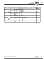
4.12
4
Installing MBG11A speed control module
•
Mounting A from the rear using 4 tapped holes.
•
Mounting B from the front using 2 retaining holes
A
B
B
M4
28 (1.1)
B
60 (2.4)
88 (3.5)
A
A
A
A
56 (2.2)
68 (2.7)
4.12.1 Connection
®
MOVITRAC B
S1
S2
ON
OFF
X44
FSC11B
X45
X46
HL ⊥ 1 2 3 4 5 6 7
Operating Instructions – MOVITRAC® B
MBG11A
1234
41
Startup
Brief description of the startup process
5
5
Startup
5.1
Brief description of the startup process
The MOVITRAC® B frequency inverter can be connected directly to a motor of the same
power. For example: A 1.5 kW (2.0 HP) motor can be connected directly to a
MC07B0015.
Procedure
1. Connect the motor to MOVITRAC® B
(terminal X2).
1-phase
3-phase
PE
2. You have the option of connecting a
braking resistor (terminal X2/X3).
쓔
3. The following signal terminals must be
controlled with your control system:
•
Enable DI∅3
•
As required CW/Stop DI∅1 or CCW/
Stop DI∅2
•
•
Changeover
REF1
Reference potential analog signals
GND
Setpoint:
•
Analog input X10 and/or
•
DI∅4 = n11 = 150 rpm or/and
•
DI∅5 = n12 = 750 rpm or/and
•
DI∅4 + DI∅5 = n13 = 1500 rpm
Fault reset
CW/stop
CCW/stop
Enable/stop*
n13 = n11 + n12
Supply voltage
input/output
Reference potential binary signals
For brakemotors: DO∅2 = Brake
control systems using brake rectifiers
•
DO∅1 = /Fault (designed as relay
contact)
•
DO∅3 = Ready
Relay contact/fault
NOC relay
NCC relay
쓔
DI∅∅ = Fault reset
X2
X3
PE
5. Check the controller for the required
functionality.
6. Connect the frequency inverter to the
mains (X1).
24VIO
Reference potential
Brake released*
Ready
Reference potential
4. You have the option of connecting the following signal terminals:
•
}
5.1.1
Shield clamp
댷
Factory setting
3-phase
5.1.2
Notes
Signal terminal functions and setpoint settings can be modified using the FBG11B keypad or a PC. A PC connection requires the FSC11B front option or one of the following
interface adapters: UWS21B / UWS11A / USB11A.
NOTE
The MOVITRAC® B frequency inverter must only be operated in strict observance of the detailed operating instructions.
42
Operating Instructions – MOVITRAC® B
Startup
General startup instructions
5.2
5
General startup instructions
HAZARD
Uncovered power connections.
Severe or fatal injuries from electric shock.
•
•
5.2.1
Install the touch guard according to the regulations.
Never start the unit if the touch guard is not installed.
Prerequisite
The drive must be configured correctly to ensure that startup is successful.
MOVITRAC® B frequency inverters are factory set to be taken into operation with the SEW
motor adapted to the correct power level (4-pole, 50 Hz) in V/f control mode.
5.2.2
Hoist applications
HAZARD
Risk of fatal injury if the hoist falls.
Severe or fatal injuries.
MOVITRAC® B may not be used as a safety device in hoist applications.
•
Use monitoring systems or mechanical protection devices to ensure safety.
Operating Instructions – MOVITRAC® B
43
I
5
Startup
Preliminary work and resources
0
5.3
Preliminary work and resources
•
Check the installation.
HAZARD
Risk of crushing if the motor starts up unintentionally.
Severe or fatal injuries.
•
•
5.3.1
5.3.2
Ensure that the motor cannot start inadvertently, for example, by removing the
electronics terminal block X13.
Additional safety precautions must be taken depending on the application to avoid
injury to people and damage to machinery, such as monitoring systems or
mechanical protection devices.
Preliminary work and resources on the MOVITRAC® B basic unit
•
Connect the supply system and the motor.
•
Connect the signal terminals.
•
Switch on the power supply system.
Preliminary work and resources on MOVITRAC® B with keypad
•
Connect the supply system and the motor. Do not connect signal terminals!
•
Switch on the power supply system.
•
The display shows Stop.
•
Program the signal terminals.
•
Set the parameters correctly (e.g. ramps).
•
Check the set terminal assignment ( P601 ... P622).
•
Switch off the power supply system.
•
Connect the signal terminals.
•
Switch on the power supply system.
NOTE
The inverter automatically changes parameter values once you perform a startup.
44
Operating Instructions – MOVITRAC® B
Startup
Optional keypad FBG11B
I
5
0
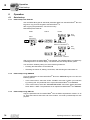
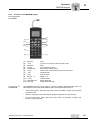
5.4
Optional keypad FBG11B
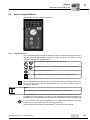
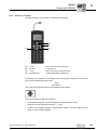
Key arrangement and symbols on keypad:
5.4.1
Keypad functions
The UP/DOWN and ENTER/OUT buttons are used for navigating through the menus.
Use the RUN and STOP/RESET buttons to control the drive. The setpoint control
module is used for setpoint specification.
Use UP/DOWN to select symbols and change values.
out
Enter
ENTER/OUT to activate and deactivate the symbols or parameter menus
Press "RUN" to start the drive.
RUN
STOP
"STOP/RESET" is used for resetting errors and for stopping the drive.
RESET
STOP
RESET
The STOP/RESET button has priority over a terminal enable or an enable via the interface. If you stop a drive using the STOP/RESET key, you have to enable it again by
pressing the RUN key.
NOTE
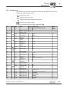
After switching off the power supply, press the STOP key to lift the lock.
The STOP/RESET key can be used for performing a reset after a fault has occurred with
a programmed error response. The drive is then inhibited and must be enabled using
the RUN key. You can deactivate the STOP function with parameter 760 using FBG11B.
RUN
If you stop the drive with the STOP/RESET key, the display Stop is flashing. This signal
indicates you have to enable the drive using the "RUN" key.
After copying the parameter set in MOVITRAC® B, the unit is also stopped.
Operating Instructions – MOVITRAC® B
45
I
5
Startup
Basic operation of the FBG11B keypad
0
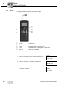
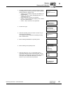
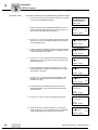
5.5
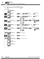
Basic operation of the FBG11B keypad
Level 1
Level 2
Display
inverter status
speed
Display
ramp up
out Enter
Modify
ramp up [s]
Enter
Modify/accept
value
Display
ramp down
out Enter
Modify
ramp down [s]
Enter
Modify/accept
value
Fixed setpoint menu
Edit mode
nxx
Selection
fixed setpoint menu
out Enter
out Enter
Enter
nmax
Display
maximum setpoint
out Enter
Par
Select
parameter menu
out Enter
Modify
maximum speed
[rpm]
Enter
Modify/accept
value
Edit mode
Parameter menu
out Enter
Enter
Select
motor startup
out Enter
Select
data backup
out Enter
Select FBG
speed ctr. module
out Enter
Modify/accept
value
Modify/accept
value
Motor statup menu
Data backup menu
FBG speed control module
Display
initial frequency
Display
output current
46
Operating Instructions – MOVITRAC® B
Startup
Basic operation of the FBG11B keypad
I
5
0
5.5.1
Menu system
The LED integrated in the symbol lights up when you select a symbol. If a symbol only
represents display values, the current display value appears immediately on the display.
5.5.2
Changing parameters
You can select the required parameter by selecting a symbol and pressing the ENTER
key.
Press the ENTER button again to edit the parameter value. You can alter the value when
the LED in the corresponding symbol flashes. When pressing the ENTER key again, the
value becomes active and the LED does not flash any longer.
5.5.3
Status display
If the status is "Drive enabled", the display will show the calculated actual speed.
5.5.4
Fault display
In the event of an error or fault, the display changes and flashes the fault code, for
example F-11 (refer to the fault list in the "Operation and Service" section). This situation
will not occur during active startup.
5.5.5
Warnings
You may not alter any parameter in any operating mode. If you try to do so, the display
r-19 ... r-32 will appear. The display shows a code depending on the action, e.g. r-28
(controller inhibit required). You find a list of warnings in the Operation and Service
section.
5.5.6
Parameter menu change short ↔ long
Using parameter P800, you can switch back and forth between short menu and long
menu. It is indicated in the parameter description and parameter list which parameters
are accessible via short and long menu.
Operating Instructions – MOVITRAC® B
47
I
5
Startup
Manual operation with FBG11B speed control module
0
5.6
Manual operation with FBG11B speed control module
FBG11B speed control module of the keypad (local manual operation): LED
flashes
The only relevant parameters in "FBG speed control module" operating mode are:
•
P122 Direction of rotation FBG manual operation
•
"RUN" and "STOP/RESET" buttons
•
Speed control module
When the FBG speed control module is activated, the symbol flashes.
You limit the smallest speed with P301 Minimum speed and the largest speed with the
nmax symbol.
After a fault, a reset can be performed using the "STOP/RESET" button via the terminal
or the interface. After a reset, the "manual speed control module" operating mode will
be active once again. The drive remains stopped.
The Stop display flashes to indicate that you have to re-enable the drive by pressing
"RUN."
The P760 Locking RUN/STOP keys parameter does not have any effect in "manual
speed control module" operating mode.
Removing the FBG11B keypad will trigger a stop response.
48
Operating Instructions – MOVITRAC® B
Startup
External setpoint selection
I
5
0
5.7
External setpoint selection
External setpoint selection
Control via
– Terminals
– Serial interface
– Setpoint potentiometer connected to AI11/AI12
5.7.1
Set direction of rotation
You can specify the set direction of rotation:
5.7.2
•
"CW/Stop and "CCW/Stop" in P101 control signal source = terminals or P101 control
signal source = 3 wire-control
•
The polarity of the setpoint in the process data word in P101 Control signal source =
RS485 or SBus and P100 Setpoint source = RS485 or SBus
Setpoint speed
You can specify the set speed:
•
Speed control module if P121 Addition FBG speed control module is set to ON
•
P100 Setpoint source
– Fixed setpoints
– Fixed setpoints with analog input
– Process data word from SBus or RS-485
– Motor potentiometer
5.7.3
Direction of rotation enable with RS-485 or SBus
Unipolar setpoint sources:
Unipolar/fixed setpoint
Motor potentiometer/fixed setpoint
Fixed setpoint + AI1
Fixed setpoint* + AI1
Frequency setpoint input/fixed setpoint
The direction of rotation is set with the CW or CCW terminals.
Bipolar setpoint sources:
Bipolar/fixed setpoint
RS-485/fixed setpoint
SBus 1/fixed setpoint
The direction of rotation is determined by the setpoint. Enable with terminal CW or CCW.
Operating Instructions – MOVITRAC® B
49
I
5
Startup
Startup using the FBG11B keypad
0
5.8
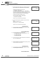
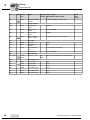
Startup using the FBG11B keypad
Level 2
Level 3
Motor selection:
– SEW DT/DV motor
Level1
– Non-SEW motor
out
Enter
– SEW DRS motor (in preparation
out
Enter
– SEW DRE motor (in preparation
Choose operating mode:
– V/f characteristic curve
– V/f + DC braking
– VFC
out
Enter
– VFC DC braking
– VFC flying start function
– VFC hoist
out
Enter
out
Enter
Power in [KW]
HP = kW x 1.33
Motor voltage [V]
out
Enter
Rated motor frequency [Hz]
(
out
Enter
out
Enter
Rated motor speed
[rpm]
Rated motor current [A]
out
Enter
out
Enter
only available for startup
of non-SEW motors
(Motor=non-SEW)
cos phi
)
4Q operation
out
50
Enter
Number of motors for
multi-motor drives
Operating Instructions – MOVITRAC® B
Startup
Startup using the FBG11B keypad
I
5
0
5.8.1
Necessary data
A successful startup requires the following data:
•
Motor type (SEW motor or non-SEW motor)
•
Motor data
– Rated voltage and rated frequency
– Additional for non-SEW motor: Rated current, rated power, power factor cos ϕ
and rated speed.
•
5.8.2
Nominal mains voltage
Activating startup
Requirements:
•
Drive ”No enable”: Stop
If a smaller or a larger motor is connected (maximum difference one size), then you have
to choose the value closest to the rated motor power.
The complete startup procedure is not complete until you have returned to the main
menu level by pressing the OUT button.
You can then perform the startup only with motor parameter set 1.
NOTE
SEW motor startup is designed for 4-pole motors. It may be useful to startup
2-pole or 6-pole SEW motors as non-SEW motors.
5.8.3
V/f
The default setting for the operating mode is V/f. Use this operating mode if you have no
particular requirements and for applications where a high maximum speed is required.
5.8.4
VFC
Startup the inverter in VFC or VFC & DC brake operating mode for the following requirements:
•
High torque
•
Continuous duty at low frequencies
•
Accurate slip compensation
•
More dynamic behavior
For this purpose, you will have to choose the VFC or VFC & DC brake operating modes
from P-01 at startup.
Operating Instructions – MOVITRAC® B
51
I
5
Startup
Startup with DBG60B
0
5.8.5
Startup of multi-motor drive
Multi-motor drives are mechanically connected to each other (e.g. chain drive with
several motors). Observe the notes in the publication "Multi-Motor Drives").
Multi-motor drives are possible with installed identical SEW motors only.
•
5.8.6
Set the multi parameter of the motor startup to the number of connected motors.
Startup of group drives
Group drives are mechanically decoupled from each other (e.g. different conveyor
belts). In this operating mode, the inverter operates without slip compensation and with
a constant V/f ratio.
You can operate a group of asynchronous motors on one inverter in V/f characteristic
curve operating mode. Important:
•
Select V/f operating mode
•
Set the power of the largest motor
•
Disable automatic adjustment P320/330
•
Set boost P321/331 to zero
•
Set IxR compensation P322/332 to zero
•
Set slip compensation P324/334 to zero
•
Set current limitation P303/313 to 1.5 times the total current of all motors
•
Set Irated UL monitoring P345/346 to the total current of the connected motors.
Implement motor protection individually.
In this operating mode, the inverter operates without slip compensation and with a
constant V/f ratio.
NOTE
The parameter settings apply to all connected motors.
5.9
Startup with DBG60B
5.9.1
Required data
The following data is required to ensure startup is successful:
•
Motor type (SEW or non-SEW motor)
•
Motor data
– Rated voltage and rated frequency
– Additionally for non-SEW motors: rated current, rated power, power factor cos ϕ
and rated speed
•
52
Rated mains voltage
Operating Instructions – MOVITRAC® B
Startup
Startup with DBG60B
I
5
0
5.9.2
Selecting a language
The figure below shows the keys for selecting the language.
[1]
[2]
[4]
[1]
[2]
[3]
[4]
[3]
↑ key
OK key
↓ key
Language key
Move up to the next menu item
Confirm entry
Move down to the next menu item
A list of languages is displayed
The following text appears on the display when the keypad is switched on for the first
time or after activating the start mode:
SEW
EURODRIVE
The symbol for language selection then appears on the display.
Proceed as follows to select the language:
•
Press the language key. A list of languages is displayed on the screen.
•
Select the desired language using the ↑ / ↓ keys
•
Confirm your language selection by pressing the OK key. The basic display is now
shown in your chosen language.
Operating Instructions – MOVITRAC® B
53
I
5
Startup
Startup with DBG60B
0
5.9.3
Startup
The figure below shows the keys required for startup.
[1]
[6]
[2]
[5]
[3]
[4]
[1]
[2]
[3]
[4]
[5]
[6]
5.9.4
↑ key
OK key
Context key
↓ key
↔ key
DEL key
Move up to the next menu item
Confirm entry
Activate the context menu
Move down to the next menu item
Change the menu, display mode ↔ edit mode
Cancel or abort startup
Startup procedure
1. Enter "0" signal at terminal X12:2 (DIØ1 "/CW/STOP), e.g.
by disconnecting X13 the electronics terminal block.
0.00rpm
0.000Amp
CONTR. INHIBIT
2. Press the context key to activate the context menu.
PARAMETER MODE
VARIABLE MODE
BASIC VIEW
3. Scroll down with the ↓ key until you have selected the
menu option "STARTUP".
54
MANUAL MODE
STARTUP
COPY TO DBG
COPY TO MDX
Operating Instructions – MOVITRAC® B
Startup
Startup with DBG60B
I
5
0
4. To startup, select the OK key. The first parameter appears.
The flashing cursor under the parameter number indicates
that the keypad is in display mode.
• Use the ↔ key to switch to edit mode. The flashing cursor disappears.
• Use the ↑ or ↓ key to select "PARAMETER SET 1" or
"PARAMETER SET 2".
• Press the OK key to confirm your selection.
• Use the ↔ key to switch back to display mode. The flashing cursor appears again.
• Use the ↑ key to choose the next parameter.
STARTUP
PREPARE FOR STARTUP
C00*STARTUP
PARAMETER SET 1
PARAMETER SET 2
5. Set the motor type.
C22*MOTORS
SINGLE MOTOR
IDENT. MOTORS
DIFFERENT MOTORS
6. Select the operating mode you require. Use the ↑ key to
choose the next parameter.
VFC operating mode is required for activating the flying
start or hoist function.
C01*OPER. MODE 1
STANDARD V/f
VFC1
a. When selecting STANDARD V/f operating mode:
C28*DC BRAKING
NO
YES
b. When selecting VFC operating mode:
C36*OPER.MODE
SPEED CONTROL
HOIST
DC BRAKING
FLYING START
7. Select the motor type. If a 2 or 4-pole SEW motor is
connected, select the correct motor from the list. If a nonSEW motor or an SEW motor with more than four poles is
connected, select "NON-SEW MOTOR" from the list.
Use the ↑ key to choose the next parameter.
C02*MOTOR TYPE 1
DT71D2
DT71D4
DT80K2
C02*MOTOR TYPE 1
NON-SEW MOTOR
DT63K4/DR63S4
Operating Instructions – MOVITRAC® B
55
5
I
Startup
Startup with DBG60B
0
8. Enter the rated motor voltage for the selected connection
type according to the value specified on the nameplate.
C03*
V
RATED MOT. VOLT 1
+400.000
Example: Nameplate 230쑶/400댴50 Hz
댴 connection → enter "400 V".
Δ connection/transition point at 50 Hz → enter "230 V".
Δ connection, transition point at 87 Hz → Also enter 230 V.
However, set parameter P302 "MAXIMUM SPEED 1" to the
value for 87 Hz after startup first. Then start the drive.
Example: Nameplate 400 Δ/690댴50 Hz
Only Δ connection possible → enter "400 V".
댴 connection is not possible.
Use the ↑ key to choose the next parameter.
9. Enter the rated frequency specified on the motor nameplate.
Example: 230Δ/400댴50 Hz
Enter "50 Hz" in 댴 and Δ connection.
C04*
Hz
RATED MOT. FREQ. 1
+50.000
Use the ↑ key to choose the next parameter.
FOR SEW MOTORS
10. The motor values are stored for SEW two and four-pole
motors and need not be entered.
C47*4-Q OPERATION
NO
YES
FOR NON-SEW MOTORS
10. Enter the following motor nameplate data:
• C10* Rated motor current, connection type 댴 or Δ .
• C11* rated motor power
• C12* power factor cos ϕ
• C13* rated motor speed
C47*4-Q OPERATION
NO
YES
11. Enter the rated power supply voltage (C05* for SEW motor,
C14* for non-SEW motor).
C05*
V
RAT. MAINS VOLT. 1
+400.000
11. Start the calculation for the startup data by choosing "YES".
The process lasts a few seconds.
C06*CALCULATION
NO
YES
FOR SEW MOTORS
12. The calculation is performed. After calculation, the next
menu item appears automatically.
C06*SAVE
NO
YES
FOR NON-SEW MOTORS
56
Operating Instructions – MOVITRAC® B
Startup
Startup with DBG60B
I
5
0
12. For non-SEW motors, a calibration process is required to
perform the calculation:
• When prompted, apply a "1" signal to terminal X12:2
(DIØ1 "/CW/STOP").
• Apply a "0" signal to terminal X12:2 again after the
calibration is complete.
• After calculation, the next menu item appears
automatically.
13. Set "SAVE" to "YES" The data (motor parameters) are
copied to the non-volatile memory of MOVIDRIVE®.
DATA IS
BEING COPIED...
14. The startup procedure is now complete. Use the DEL key
to return to the context menu.
MANUAL MODE
STARTUP
COPY TO DBG
COPY TO MC07B
15. Use the ↓ key to scroll down until the menu item "EXIT" is
selected.
EXIT UNIT
SETTINGS
16. Confirm your selection by selecting OK. The basic display
appears.
0.00rpm
0.000Amp
CONTR. INHIBIT
HAZARD
Parameter settings incorrect due to unsuitable data sets.
Severe or fatal injury.
Make sure that the data set you copy is suitable for the application.
•
Enter any parameter settings which differ from the factory settings in the parameter
list.
•
In the case of non-SEW motors, set the correct brake application time (P732 / P735).
•
Observe the notes for starting the motor in the section "Starting the Motor".
•
With Δ connection and transition point at 87 Hz, set parameter P302/312 "Maximum
speed ½" to the value for 87 Hz.
Operating Instructions – MOVITRAC® B
57
I
5
Startup
Startup with DBG60B
0
5.9.5
Setting parameters
Proceed in this order to set the parameters:
5.9.6
•
Use the context key to call up the context menu. In the context menu, select the
"PARAMETER MODE" menu item. Press the OK key to confirm your selection. The
flashing cursor under the parameter number indicates that the keypad is in parameter
mode.
•
Use the ↔ key to switch to edit mode. The flashing cursor disappears.
•
Using the ↑ or ↓ key, you can select or set the correct parameter value.
•
Press the OK key to confirm the selection or setting.
•
Use the ↔ key to switch back to parameter mode again. The flashing cursor appears
again.
•
Use the ↑ key to choose the next parameter.
Manual operation
The inverter can be controlled using the DBG60B keypad in manual operation (Context
menu → Manual operation). The 7-segment display on the unit shows "H" during manual
operation.
The binary inputs will be without any functions for the duration of manual operation, with
the exception of a /Controller inhibit. A binary input "/Controller inhibit" must be assigned
a "1" signal to enable the drive to be started in manual operation.
The direction of rotation is not determined by the "CW/stop" or "CCW/stop" binary inputs. Instead, you select the direction of rotation using the DBG60B keypad.
•
Enter the required speed and then the direction of rotation (+ = CW/– = CCW) using
the sign key (+/–).
Manual operation remains active when the power supply is switched off and on; however, the inverter is then inhibited.
•
Use the "Run" key to enable and start the inverter at nmin in the selected direction of
rotation. The speed is increased and decreased using the ↑ and ↓ keys.
NOTE
The signals at the binary inputs take effect as soon as manual operation is finished. A
binary input /Controller inhibit does not have to be switched from "1" to "0" and back to
"1". The drive can start according to the signals at the binary inputs and the setpoint
sources.
HAZARD
Risk of crushing if the motor starts up unintentionally.
Severe or fatal injuries.
•
•
58
Ensure that the motor cannot start inadvertently, for example, by removing the
electronics terminal block X13.
Additional safety precautions must be taken depending on the application to avoid
injury to people and damage to machinery.
Operating Instructions – MOVITRAC® B
Startup
Startup with PC and MOVITOOLS® MotionStudio
I
5
0
5.10
Startup with PC and MOVITOOLS® MotionStudio
Start MOVITOOLS® MotionStudio in the Windows start menu:
Programs / SEW / MOVITOOLS MotionStudio 5.x/MotionStudio 5.x
Press the MOVITOOLS® MotionStudio [Scan] button to list all connected units in the unit
tree.
You can perform a startup by right-clicking on one of the units. You can find additional
information in the online Help.
5.11
Startup for MBG11A speed control module
You cannot simultaneously establish communication between MOVITRAC® B /
MBG11A and MOVITRAC® B / PC.
The MBG11A can simultaneously specify a setpoint for up to 31 MOVITRAC® B units.
5.11.1 Parameter settings
The following parameters must be set other than the factory setting in MOVITRAC® B.
When you use a FBG11B for setting the parameters, set the values indicated in
parenthesis:
•
P100: RS 485 (2)
•
P101: RS 485 (1)
•
P871: Set PA2 to "Speed [%]", then P876 PA data enable to "Yes".
The speed is now displayed:–100 % ... 100 % correspond to –nmax ... nmax.
5.11.2 Input terminals
The following input terminals must be connected with 24 V:
•
DI01 CW/Stop:positive + negative direction of rotation are possible by selecting the
+/- sign on the MBG11A.
•
DI03 Enable/Stop
Operating Instructions – MOVITRAC® B
59
I
5
Startup
Starting up pumps and fans of non-SEW motors
0
5.11.3 Settings for process data word
If you do not change the PO2 process data word, you can also use the MBG11B. In this
case, the conversion is 1 % = 32 rpm. The results from the relationship 4000 hex =
100 % speed. Refer to the following tables for the respective value.
PO2 = Speed (standard parameter setting P871 = speed)
Percent
Decimal
Speed
1%
Hex
A4 hex
164
32
10 %
666 hex
1638 dec
328
25 %
1000 hex
4096 dec
819.2
33 %
1555 hex
5461 dec
1092.3
50 %
2000 hex
8192 dec
1638.4
75 %
3000 hex
12288 dec
2457.6
100 %
4000 hex
16384 dec
3276.8
dec
PO2 = Speed [%] (changed parameter setting P871 = speed [%])
Percent
5.12
Decimal
Speed
1%
Hex
A4 hex
164
n_max / 100
10 %
666 hex
1638 dec
n_max / 10
25 %
1000 hex
4096 dec
n_max / 4
33 %
1555 hex
5461 dec
n_max / 3
50 %
2000 hex
8192 dec
n_max / 2
75 %
3000 hex
12288 dec
n_max / 1.333
100 %
4000 hex
16384 dec
n_max
dec
Starting up pumps and fans of non-SEW motors
We recommend that you adjust the following parameters when using pumps, fans, and
non-SEW motors due to the physical conditions of the application :
•
Operation of the drive in the V/F characteristic curve operating mode;
Parameter 700 / 701 = V/f characteristic curve (21)
•
Disable automatic adjustment; Parameter 320 / 330 = Off (0)
•
Set IxR adjustment to 0; Parameter 322 / 332 = 0
•
Set boost to 0; Parameter 321 / 331 = 0
•
Minimize slip compensation and set to 0 if required; Parameter 324 / 334
•
Increase ramp times; Parameters 130 / 140 and 131 / 141
Deactivating the slip compensation might require that you specify a higher setpoint
speed to achieve the required air/volume flow.
60
Operating Instructions – MOVITRAC® B
Startup
Starting the motor
I
5
0
5.13
Starting the motor
5.13.1 Analog setpoint specification
The following table shows which signals must be present on terminals X11:2 (AI1) and
X12:1 … X12:4 (DIØØ … DIØ3) when the "unipolar/fixed setpoint" setpoint is selected
(P100) in order to operate the drive with an analog setpoint entry.
Function
X11:2
(AI11)
Analog
input n1
X12:1
(DIØØ)
/Controller
inhibit1)
X12:2
(DIØ1)
CW/stop
X12:3
(DIØ2)
CCW/
stop
X12:4
(DIØ3)
Enable/
stop
X12:5
(DIØ4)
n11/n21
X12:6
(DIØ5)
n12/n22
Controller inhibit
X
0
X
X
X
0
0
Stop
X
1
X
X
0
0
0
Enable
and stop
X
1
0
0
1
0
0
Clockwise at
50 %
nmax
5V
1
1
0
1
0
0
Clockwise with
nmax
10 V
1
1
0
1
0
0
Counterclockwise with
50 %
nmax
5V
1
0
1
1
0
0
Counterclockwise with
nmax
10 V
1
0
1
1
0
0
1) No default setting
Operating Instructions – MOVITRAC® B
61
5
I
Startup
Starting the motor
0
The following travel cycle shows by way of example how the motor is started with the
assignment of terminals X12:1 … X12:4 and analog setpoints. Binary output X10:3
(DBØØ "/Brake") is used for switching brake contactor K12.
"1"
Input DIØØ
/Controller inhibit
"0"
"1"
Input DIØ1
CW/Stop
"0"
"1"
Input DIØ2
CCW/Stop
"0"
"1"
Input DIØ3
Enable /
Stop
"0"
Output DBØØ
/Brake
"1"
"0"
10V
Analog
input n1 (AI11) 5V
0V
n [rpm ]
nmax
Speed
50 % nmax
nmin
nstart-stop
0
-50 % nmax
t11 up
t11 up
t11 up
t11 down
t11 down
t11 up
Stop ramp t13
-nmax
NOTE
The motor is not energized in the event of controller inhibit. A motor without brake will
coast to standstill.
62
Operating Instructions – MOVITRAC® B
Startup
Starting the motor
I
5
0
5.13.2 Fixed setpoints
The following table shows which signals must be present on terminals X12:1 … X12:6
(DIØØ … DIØ5) when the "unipolar/fixed setpoint" setpoint is selected (P100), in order
to operate the drive with the fixed setpoints.
Function
X12:1
(DIØØ)
/Controller inhibit
X12:2
(DIØ1)
CW/stop
X12:3
(DIØ2)
CCW/stop
X12:4 (DIØ3)
Enable/stop
X12:5
(DIØ4)
n11/n21
X12:6
(DIØ5)
n12/n22
Controller
inhibit
0
X
X
X
X
X
Stop
1
X
X
0
X
X
Enable and
stop
1
0
0
1
X
X
CW operation with n11
1
1
0
1
1
0
CW operation with n12
1
1
0
1
0
1
CW operation with n13
1
1
0
1
1
1
CCW operation with n11
1
0
1
1
1
0
Operating Instructions – MOVITRAC® B
63
5
I
Startup
Starting the motor
0
The following travel cycle shows by way of example how the drive is started with the
assignment of terminals X12:1 … X12:6 and the internal fixed setpoints. Binary output
X10:3 (DBØØ "/Brake") is used for switching brake contactor K12.
"1"
Input DIØØ
/Controller inhibit
"0"
"1"
Input DIØ1
CW/Stop
"0"
"1"
Input DIØ2
CCW/Stop
"0"
"1"
Input DIØ3
Enable /
Stop
"0"
"1"
Input DIØ4
n11/n21
"0"
"1"
Input DIØ5
n12/n22
"0"
Output DBØØ
/Brake
"1"
"0"
Speed
n [rpm ]
n13
t11 up
n12
n11
0
-n11
-n12
t11 up
t11 down
t11 up
t11 up
Stop ramp t13
-n13
NOTE
The motor is not energized in the event of controller inhibit. A motor without brake will
coast to standstill.
64
Operating Instructions – MOVITRAC® B
Startup
Parameter list
I
5
0
5.14
Parameter list
All parameters that can also be displayed and edited using the keypad are indicated as
follows in the "FBG" (keypad) column:
Selection in long menu
Selection in short or long menu
Selection using symbol on keypad and in long menu
Selection within FGB motor startup
If a choice is offered, the factory setting is indicated in bold.
No.
FBG Index
dec.
Name
Range / factory setting
Display
0__
Display values (read only)
00_
Process values
MOVITOOLS®
000
8318
Speed (signed)
[rpm]
001
8501
User display for
DBG11B
[Text]
002
8319
Frequency
(signed)
[Hz]
004
8321
Output current
(amount)
[% IN]
005
8322
Active current
(signed)
[% IN]
008
8325
DC link voltage
[V]
009
8326
Output current
[A]
01_
MotionStudio
Value
after
startup
Status displays
010
8310
Inverter status
[Text]
011
8310
Operating state
[Text]
012
8310
Error status
[Text]
013
8310
Current
parameter set
Current parameter set
014
8327
Heat sink
temperature
[°C]
02_
Analog setpoints
020
8331
Analog input AI1
[V]
021
8332
Analog input AI2
(optional)
[V]
03_
Binary inputs
030
8844
Binary input DI00
031
8335
Binary input DI01
CW / STOP (fixed assignment)
032
8336
Binary input DI02
CCW/stop
033
8337
Binary input DI03
Enable/stop
034
8338
Binary input DI04
n11/n21
035
8339
Binary input DI05
n12/n22
Operating Instructions – MOVITRAC® B
Fault reset
65
I
5
Startup
Parameter list
0
No.
039
FBG Index
dec.
8334
05_
Range / factory setting
Display
Binary inputs DI00
... DI05
MOVITOOLS®
MotionStudio
Binary outputs
8349
Binary output
DO01
/FAULT
052
8349
Binary output
DO02
Brake released
053
8349
Binary output
DO03
Ready
059
8349
Binary outputs
DO01 ... DO03
Collective display of binary outputs
Unit data
070
8301
Unit type
[Text]
071
8361
Rated output
current
[A]
076
8300
Firmware basic
unit
[Part number and version]
077
–
DBG firmware
Only in DBG60B
08_
080 ... 084
Value
after
startup
Collective display of binary inputs
051
07_
Error memory
8366 ...
8370
09_
66
Name
Error t-0 ... t-4
Error
code
Background information for previous faults.
Bus diagnostics
094
8455
PO1 setpoint
[hex]
095
8456
PO2 setpoint
[hex]
096
8457
PO3 setpoint
[hex]
097
8458
PI1 actual value
[hex]
098
8459
PI2 actual value
[hex]
099
8460
PI3 actual value
[hex]
Operating Instructions – MOVITRAC® B
Startup
Parameter list
I
5
0
No.
FBG Index
dec.
Name
Range / factory setting
Display
MOVITOOLS®
MotionStudio
1__
Setpoints / ramp generators (on FBG only parameter set 1)
10_
Setpoint selection / frequency input
100
8461
Setpoint source
0
1
2
4
6
7
8
9
10
11
14
Bipolar/fixed setpoint
Unipolar/fixed setpoint
RS-485/fixed setpoint
Motor potentiometer/fixed setpoint
Fixed setpoint + AI1
Fixed setpoint* + AI1
MASTER SBus1
MASTER RS-485
SBus 1/fixed setpoint
Frequency setpoint input / Fixed setpoint
Bipolar AI2 / Fixed setpoint
101
8462
Control signal
source
0
1
3
4
Terminals
RS -485
SBus 1
3-wire control
102
8840
Frequency scaling 0.1 ... 10 ... 120.00 [kHz]
103
10247.15
FI1 reference
0
1
104
10247.10
Setpoint
reference speed
nreference
0 ... 3000 ... 6000 rpm
105
10416.1
Wire breakage
detection
0
2
4
7
106
10247.11
FI1 char. curve x1
0 ... 100 %
107
10247.12
FI1 char. curve y1
–100 % ... 0 ... +100 %
108
10247.13
FI1 characteristic
x2
0 ... 100 %
109
10247.14
FI1 characteristic
curve y2
–100 % ... 0 ... +100 %
11_
Value
after
startup
nmax
nreference
No response
Immediate stop / fault
Rapid stop / fault
Rapid stop / warning
Analog input 1 (0 ... 10 V)
110
8463
AI1 scaling
0.1 ... 1 ... 10
112
8465
AI1 Operating
mode
1
5
6
7
8
9
113
8466
AI1 voltage offset
–10 V ... 0 ... +10 V
116
10247.6
AI1 characteristic
curve x1
0 ... 100 %
117
10247.7
AI1 characteristic
curve y1
–100 % ... 0 ... +100 %
118
10247.8
AI1 characteristic
curve x2
0 ... 100 %
119
10247.9
AI1 characteristic
curve y2
–100 % ... 0 ... +100 %
Operating Instructions – MOVITRAC® B
10 V, reference maximum speed
0 - 20 mA, reference maximum speed
4 - 20 mA, reference maximum speed
0 - 10 V, n-reference
0 - 20 mA, n-reference
4 - 20 mA, n-reference
67
I
5
Startup
Parameter list
0
No.
FBG Index
dec.
12_
Range / factory setting
Display
MOVITOOLS®
MotionStudio
Value
after
startup
Analog input AI2 / FBG speed control module (option)
120
8469
AI2 operating
mode
0
1
2
No function
0 ... ±10 V + Setpoint
0 ... 10 V current limitation
121
8811
Addition FBG
setpoint control
module
0
1
2
Off
On
On (without fixed setpoint)
122
8799
Direction of rotation FBG manual
operation
0
1
2
Unipolar CW
Unipolar CCW
Bipolar CW and CCW
126
10247.1
AI2 char. curve x1
–100 % ... 0 ... +100 % (–10 V ... 0 ... +10 V)
127
10247.2
AI2 char. curve y1
–100 % ... 0 ... +100 % (–nmax ... 0 ... +nmax / 0 ... Imax)
128
10247.3
AI2 characteristic
curve x2
–100 % ... 0 ... +100 % (–10 V ... 0 ... +10 V)
129
10247.4
AI2 characteristic
curve y2
–100 % ... 0 ... +100 % (–nmax ... 0 ... +nmax / 0 ... Imax)
13_ / 14_
Speed ramps 1 / 2
130 / 140
8807 /
9264
Ramp t11 / t21 up
0.1 ... 2 ... 2000 [s]
131 / 141
8808 /
9265
Ramp t11 / t21
down
0.1 ... 2 ... 2000 [s]
134 / 144
8474 /
8482
Ramp t12 / t22
0.1 ... 10 ... 2000 [s]
135 / 145
8475 /
8483
S pattern t23/t22
0
1
2
3
136 / 146
8476 /
8484
Stop ramp t13 /
t23
0.1 ... 2 ... 20 [s]
139 / 149
8928 /
8929
Ramp monitoring
1/2
0
1
15_
Off
Weak
Medium
Strong
YES
NO
Motor potentiometer function
150
8809
Ramp t3 up =
down
0.2 ... 20 ... 50 [s]
152
8488
Save last setpoint
Off
On
16_ / 17_
68
Name
Off
On
Fixed setpoints
160 / 170
8489 /
8492
Internal setpoint
n11 / n21
0 ... 150 ... 5000 [rpm]
161 / 171
8490 /
8493
Internal setpoint
n12 / n22
0 ... 750 ... 5000 [rpm]
162 / 172
8491 /
8494
Internal setpoint
n13 / n23
0 ... 1500 ... 5000 [rpm]
163 / 173
8814 /
8817
n11/n21 PI
controller
0 ... 3 ... 100 [%]
164 / 174
8815 /
8818
n12/n22 PI
controller
0 ... 15 ... 100 [%]
165 / 175
8816 /
8819
n13/n23 PI
controller
0 ... 30 ... 100 [%]
Operating Instructions – MOVITRAC® B
Startup
Parameter list
I
5
0
No.
FBG Index
dec.
Name
Range / factory setting
Display
2__
Controller parameters
25_
PI controller
MOVITOOLS®
MotionStudio
Off
Normal
Inverted
250
8800
PI controller
0
1
2
251
8801
P-gain
0 ... 1 ... 64
252
8802
I-component
0 ... 1 ... 2000 [s]
253
8465
PI actual value
mode
1
5
6
7
8
9
254
8463
PI actual value
scaling
0.1 ... 1.0 ... 10.0
255
8812
PI actual value
offset
0.0 ... 100.0 [%]
10 V, reference maximum speed
0 - 20 mA, reference maximum speed
4 - 20 mA, reference maximum speed
0 - 10 V, n-reference
0 - 20 mA, n-reference
4 - 20 mA, n-reference
3__
Motor parameters (on FBG only parameter set 1)
30_ / 31_
Limits 1 / 2
300 / 310
8515 /
8519
Start/stop speed 1
/2
0 ... 150 [rpm]
301 / 311
8516 /
8520
Minimum speed 1
/2
0 ... 15 ... 5500 [rpm]
302 / 312
8517 /
8521
Maximum speed 1
/2
0 ... 1500 ... 5500 [rpm]
303 / 313
8518 /
8522
Current limit 1 / 2
0 ... 150 [% IN]
32_ / 33_
Motor adjustment 1 / 2
320 / 330
8523 /
8528
Automatic
adjustment 1 / 2
Off
On
321 / 331
8524 /
8529
Boost 1 / 2
0 ... 100 [%]
322 / 332
8525 /
8530
IxR compensation 1 / 2
0 ... 100 [%]
323 / 333
8526 /
8531
Pre-magnetization time 1 / 2
0 ... 2 [s]
324 / 334
8527 /
8532
Slip compensation 1 / 2
0 ... 500 [rpm]
Off
On
IN UL monitoring
34_
345 / 346
Value
after
startup
9114 /
9115
IN UL monitoring 1
/2
Operating Instructions – MOVITRAC® B
0.1 ... 500 A
69
I
5
Startup
Parameter list
0
No.
FBG Index
dec.
Range / factory setting
Display
4__
Reference messages
40_
Speed reference message
MOVITOOLS®
400
8539
Speed reference
value
0 ... 750 ... 5000 [rpm]
401
8540
Hysteresis
0 ... 100 ... +500 [rpm]
402
8541
Delay time
0 ... 1 ... 9 [s]
403
8542
Signal = "1" when
0
1
43_
MotionStudio
Value
after
startup
n < nref
n > nref
Current reference signal
430
8550
Current reference
value
0 ... 100 ... 150 % IN
431
8551
Hysteresis
0 ... 5 ... 30 % IN
432
8552
Delay time
0 ... 1 ... 9 s
433
8553
Signal = "1" when
0
1
44_
I < Iref
I > Iref
Imax signal
440
8554
Hysteresis
0 ... 5 ... 50 % IN
441
8555
Delay time
0 ... 1 ... 9 s
442
8556
Signal = "1" when
0
1
45_
I < Imax
I > Imax
PI controller reference signal
450
8813
PI actual value
reference
451
8796
Signal = "1" when
0
1
PI Actual value < PI ref
PI Actual value > PI ref
5__
Monitoring parameters (on FBG only parameter set 1)
50_
Speed monitoring 1 / 2
500 / 502
8557 /
8559
Speed monitoring
1/2
0
3
501 / 503
8558 /
8560
Delay time 1 / 2
0 ... 1 ... 10 [s]
54_
70
Name
Off
Motor / regenerative
Gear unit/motor monitoring
540
9284
Response to drive
vibration / warning
Factory setting: Display fault
541
9285
Response to drive
vibration / fault
Factory setting: Rapid stop / warning
542
9286
Response to oil
aging / fault
Factory setting: Display fault
543
9287
Response to oil
aging / warning
Factory setting: Display fault
544
9288
Oil aging / overtemperature
Factory setting: Display fault
545
9289
Oil aging / ready
signal
Factory setting: Display fault
549
9290
Response to
brake wear
Factory setting: Display fault
Operating Instructions – MOVITRAC® B
Startup
Parameter list
I
5
0
No.
FBG Index
dec.
Name
Range / factory setting
Display
6__
Terminal assignment
60_
Binary inputs
601
8336
Binary input DI02
assignment
602
8337
Binary input DI03
assignment
603
8338
Binary input DI04
assignment
604
8339
Binary input DI05
assignment
608
8844
Binary input DI00
assignment
62_
MOVITOOLS®
MotionStudio
Value
after
startup
0: No function
1: Enable / stop (factory setting DI03)
2: CW/stop
3: CCW / stop (factory setting DI02)
4: n11 / n21 (factory setting DI04)
5: n12 / n22 (factory setting DI05)
n13 = n11 + n12
6: Fixed setpoint switchover
7: Parameter set switchover
8: Ramp switchover
9: Motor potentiometer up
10: Motor potentiometer down
11: /External fault
12: Fault reset (factory setting DI00)
19: Slave free running
20: Setpoint acceptance active
26: TF signal (only with DI05)
27: Vibration/warning
28: Vibration/fault
29: Brake wear
30: Controller inhibit
33: Oil aging/warning
34: Oil aging/fault
35: Oil aging / overtemperature
36: Oil aging/ready
Binary outputs
620
8350
Binary output
DO01 assignment
621
8351
Binary output
DO02 assignment
622
8916
Binary output
DO03 assignment
Operating Instructions – MOVITRAC® B
0: No function
1: /Fault (factory setting DO01)
2: Ready (factory setting DO03)
3: Output stage on
4: Rotating field on
5: Brake released (factory setting DO02 / not
with DO03)
8: Parameter set
9: Speed reference message
11: Comparison message setpoint-actual
value
12: Current reference message
13: Imax signal
21: IPOS output
22: /IPOS fault
23: PI controller actual value reference
24: Ex-e current limit active (in preparation)
27: Safe stop
30: Ixt warning
31: Ixt fault
71
I
5
Startup
Parameter list
0
No.
FBG Index
dec.
64_
Range / factory setting
Display
MOVITOOLS®
MotionStudio
8568
Analog output
AO1
0
1
2
3
4
5
6
7
11
12
No function
Ramp generator input
Setpoint speed
Actual speed
Actual frequency
Output current
Active current
Unit utilization
Actual speed (signed)
Actual frequency (signed)
641
10248.5
AO1 reference
0
1
2
3000 rpm , 100 Hz, 150 %
nmax
nset reference
642
8570
AO1 Operating
mode
0
2
3
4
No function
0 ... 20 mA
4 ... 20 mA
0 ... 10 V
646
10246.1
AO1 Characteristic curve x1
–100 % ... 0 ... +100 %
647
10246.2
AO1 Characteristic curve y1
0 ... 100 %
648
10246.3
AO1 Characteristic curve x2
–100 % ... 0 ... +100 %
649
10246.4
AO1 Characteristic curve y2
0 ... 100 %
7__
Control functions (on FBG only parameter set 1)
70_
Operating modes 1 / 2
8574 /
8575
71_
710 / 711
Value
after
startup
Analog outputs AO1 (optional)
640
700 / 701
Operating mode 1
/2
0
2
3
4
21
22
VFC
VFC & HOIST
VFC & DC braking
VFC & flying start function
V/f characteristic curve
V/f & DC braking
Standstill current 1 / 2
8576 /
8577
72_
Standstill current
1/2
0 ... 50 % IMot
Setpoint stop function 1 / 2
720 / 723
8578 /
8581
Setpoint stop
function 1 / 2
721 / 724
8579 /
8582
Stop setpoint 1 / 2 0 ... 30 ... 500 [rpm]
722 / 725
8580 /
8583
Start offset 1 / 2
73_
72
Name
Off
On
Off
On
0 ... 30 ... 500 [rpm]
Brake function 1 / 2
731 / 734
8749 /
8750
Brake release
time 1 / 2
0 ... 2 [s]
732 / 735
8585 /
8587
Brake application
time 1 / 2
0 ... 2 [s]
Operating Instructions – MOVITRAC® B
Startup
Parameter list
I
5
0
No.
FBG Index
dec.
74_
Name
Range / factory setting
Display
MOVITOOLS®
Speed skip function
740 / 742
8588 /
8590
Skip window center 1 / 2
0 ... 1500 ... 5000 rpm
741 / 743
8589 /
8591
Skip width 1 / 2
0 ... 300 rpm
75_
Master/slave function
750
8592
Slave setpoint
751
8593
Scaling slave
setpoint
76_
760
Manual operation
8798
77_
770
MotionStudio
Value
after
startup
Lock RUN / STOP
buttons
Off
On
Off
On
Energy-saving function
8925
Energy-saving
function
Off
On
Off
On
8__
Unit function (on FBG only parameter set 1)
80_
Setup
800
–
Short menu
801
–
DBG language
802
8594
Factory setting
no
Hours
ALL
NEMA
0 / No
1 / Standard
2 / Delivery status
4 / NEMA delivery status
803
8595
Parameter lock
Off
On
Off
On
804
8596
Reset statistics
data
No action
Error memory
805
–
Rated mains voltage
50 ... 500 V
806
–
Copy DBG →
MOVITRAC® B
Yes
No
807
–
Copy MOVITRAC® B → DBG
Yes
No
808
8660
24 V output voltage
Off
On
809
10204.1
IPOS enable
Off
On
81_
long
short
Serial communication
810
8597
RS-485 address
0 ... 99
811
8598
RS-485 group
address
100 ... 199
812
8599
RS-485 timeout
interval
0 ... 650 [s]
Operating Instructions – MOVITRAC® B
73
I
5
Startup
Parameter list
0
No.
FBG Index
dec.
82_
820 / 821
8607 /
8608
Display
MOVITOOLS®
MotionStudio
Value
after
startup
4-quadrant
operation 1 / 2
Off
On
Off
On
Fault responses
830
8609
833
8612
836
8615
84_
Response termi2
nal "external fault" 4
Response to RS- 7
485 timeout
Immediate stop / fault
Rapid stop / fault (830)
Rapid stop / warning (833 / 836)
Response to
SBus timeout
Reset behavior
8617
85_
Manual reset
Yes
No
Scaling actual speed value
850
8747
Scaling factor
numerator
1 ... 65535 (can be set with SHELL only)
851
8748
Scaling factor
denominator
1 ... 65535 (can be set with SHELL only)
852
8772 /
8773
User-defined unit
Text
853
9312
Scaled speed
FBG
0
1
Speed
Scaled speed
86_
Modulation 1 / 2
860 / 861
8620 /
8621
PWM frequency 1
/2
4
8
12
16
4 kHz
8 kHz
12 kHz
16 kHz
862 / 863
8751 /
8752
PWM fix 1 / 2
On
Off
On
Off
87_
74
Range / factory setting
Brake operation 1 / 2
83_
840
Name
Process data parameter setting
870
8304
Setpoint
description PO1
871
8305
Setpoint
description PO2
872
8306
Setpoint
description PO3
873
8307
Actual value
description PI1
874
8308
Actual value
description PI2
875
8309
Actual value
description PI3
876
8622
PO data enable
No function (factory setting P872)
Setpoint speed (factory setting P871)
Max. speed
Ramp
Control word 1 (factory setting P870)
Control word 2
Setpoint speed [%]
IPOS PO data
PI controller setpoint [%]
No function
Actual speed (factory setting P874)
Output current (factory setting P875)
Active current
Status word 1 (factory setting P873)
Actual speed [%]
IPOS PI-DATA
PI controller actual value [%]
No
Yes
Operating Instructions – MOVITRAC® B
Startup
Parameter list
I
5
0
No.
FBG Index
dec.
88_
880
Name
Range / factory setting
Display
MOVITOOLS®
MotionStudio
Value
after
startup
Serial communication SBus
8937
SBus protocol
0 / MoviLink
1 / CANopen
881
8600
SBus address
0 ... 63
882
8601
SBus group
address
0 ... 63
883
8602
SBus timeout
interval
0 ... 650 [s]
884
8603
SBus baud rate
125
250
500
1000
886
8989
CANopen
address
1 ... 2 ... 127
Operating Instructions – MOVITRAC® B
125 kbaud
250 kbaud
500 kbaud
1 MBaud
75
I
6
Operation
Data backup
0
6
Operation
6.1
Data backup
6.1.1
Data backup with FBG11B
Use the FBG11B keypad to download parameter data from the MOVITRAC® B to the
keypad or copy from the keypad to the MOVITRAC® B.
After copying the parameters, check for accuracy.
Data backup with FBG11B
Level 1
Level 3
Level 2
Enter
Start
loading
Select
data backup
out Enter
Enter
Parameter data from
FBG11B MOVITRAC® B
Enter
Start
saving
Enter
Parameter data from
MOVITRAC® B FBG11B
After copying data, the MOVITRAC® B is inhibited. The inhibited status is indicated by
a flashing STOP in the status display. The status LED also slowly flashes yellow.
You can lift the inhibit by taking one of the following measures:
6.1.2
•
Pressing the RUN button on the FBG11B
•
Switching the mains off, waiting 10 seconds, and switching the mains back on
Data backup using DBG60B
Copy the parameter set from MOVITRAC® B into the DBG60B keypad. You have the
following options:
6.1.3
•
In the context menu, select the "COPY TO DBG" menu item. Confirm your selection
by pressing OK. The parameter set is copied from MOVITRAC® B to DBG60B.
•
In the context menu, select the "PARAMETER MODE" menu item. Select parameter
P807 "MCB → DBG". The parameter set is copied from MOVITRAC® B to DBG60B.
Data backup using UBP11A
Copy the parameter set from MOVITRAC® B to the UBP11A parameter module. To do
so, press the button at the lower end of the module. You need a pointed object for this
purpose.
76
Operating Instructions – MOVITRAC® B
Operation
Return codes (r-19 ... r-38)
I
6
0
6.1.4
Data backup using MOVITOOLS® MotionStudio
When you use MOVITOOLS® MotionStudio to transfer data to the MOVITRAC® B
frequency inverter, you must re-enable the inverter as follows:
•
Select unit in the network.
•
Right click to open the context menu.
•
Select menu [RUN/STOP via software keypad] [1]
•
Select [RUN] in the software keypad [2]
[1]
[2]
6.2
Return codes (r-19 ... r-38)
Return codes MOVITRAC® B:
No.
Designation
Meaning
19
Parameter lock activated
Parameters cannot be changed
20
Factory setting in progress
Parameters cannot be changed
23
Option card missing
The option card required for the function is missing.
27
Option card missing
The option card required for the function is missing.
28
Controller inhibit required
Controller inhibit required
29
Invalid value for parameter.
•
•
32
Enable
You cannot perform this function in ENABLED status
34
Error during execution
•
•
38
FBG11B incorrect data set
Stored data set does not match the unit
Operating Instructions – MOVITRAC® B
Invalid value for parameter.
FGB manual operation selection invalid as PC is
in active manual operation.
Error while saving in FBG11B.
Startup not performed with FBG. Perform FGB
startup with MotionStudio or select a new motor.
77
I
6
Operation
Status displays
0
6.3
Status displays
6.3.1
FBG11B keypad
If the status is "Drive enabled", the display will show the calculated actual speed.
Status of binary
inputs/outputs
Status
Display
Drive "Controller inhibit"
oFF
Drive "No enable"
StoP
Drive "Enable"
8888 (actual speed)
Factory setting
SEt (Set)
Standstill current
dc
24 V operation
24U
Parameter P039 (binary inputs) and parameter P059 (binary outputs) are adopted in the
parameter menu as display parameters. The status is displayed as binary. Every binary
input or output has two segments vertically on top of one another of the 7-segment
display assigned to it. The upper segment lights up when the binary input or output is
set, and the lower segment lights up when the binary input or output is not set. The two
7-segment displays on the right are displayed if P039 (di = binary inputs ) or P059 (do =
binary outputs) are output.
Examples:
Top: Input status: DI00 = 1 / DI01 = 0 / DI02 = 1 / DI03 = 1 / DI04 = 1 / DI05 = 0
Bottom: Output status: DO01 = 1 / DO02 = 0 / DO03 = 1
78
Operating Instructions – MOVITRAC® B
Operation
Unit status codes
I
6
0
6.3.2
LED flash codes
The LED on the front of the unit signals the following states:
Status
Display (optional with
FBG)
LED flash code status of basic
unit
"ENABLE"
Speed
Constant green light
"ENABLE" at current limit
Speed flashes
Rapid green flashing
"CURRENT AT STANDSTILL"
dc
Slow green flashing
Timeout
Errors 43 / 46 / 47
Flashing green/yellow
"NO ENABLE"
Stop
Constant yellow light
"FACTORY SETTING"
SEt
Rapid yellow flashing
"CONTROL.INHIBIT"
oFF
Rapid yellow flashing
"24 V operation"
Flashing 24U
Slow yellow flashing
"SAFE STOP"
Flashing U
Slow yellow flashing
FGB manual operation
active or inverter stopped
using "stop" button.
FGB manual operation
symbol or "stop" is flashing
Yellow on long, off briefly
Copy
Fault 97
Flashing red/yellow
System fault
Faults 10 / 17 ... 24 / 25 / 32
/ 37 / 38 / 45 / 77 / 80 / 94
Constant red light
Overvoltage / phase failure
Faults 4 / 6 / 7
Slow red flashing
Overload
Faults 1 / 3 / 11 / 44 / 84
Rapid red flashing
Monitoring
Faults 8 / 26 / 34 / 81 / 82
2 x red flashing
Motor protection
Faults 31 / 84
3 x red flashing
WARNING!
Incorrect interpretation of display U = "Safe stop" active.
Severe or fatal injuries.
The display U = "Safe stop" is not safety-related and must not be used as a safety
function.
6.4
Unit status codes
Use status word 1 to determine the unit status code.
Code
Meaning
0x0
Not ready
0x1
Controller inhibit
0x2
No enable
0x3
Standstill current active, no enable
0x4
Enable
0x8
Factory setting is active
Operating Instructions – MOVITRAC® B
79
Operation
DBG60B keypad
6
6.5
DBG60B keypad
6.5.1
Basic displays
0.00rpm
0.000Amp
CONTR. INHIBIT
Display when /CONTROLLER INHIBIT = "0".
0.00rpm
0.000Amp
NO ENABLE
Display when inverter is not enabled ("ENABLE/STOP" = "0").
950.00rpm
0.990Amp
ENABLE (VFC)
Display for enabled inverter.
NOTE 6:
VALUE TOO HIGH
FAULT
STARTUP
6.5.2
(DEL)=Quit
9
Information message
Fault display
Information messages
Information messages on the DBG60B (ca. 2 s in duration) or in MOVITOOLS® MotionStudio/SHELL (message that can be acknowledged):
No.
Text DBG60B/SHELL
Description
1
ILLEGAL INDEX
Index addressed via interface not available.
2
NOT IMPLEMENT.
•
•
•
3
READ ONLY VALUE
Attempt to modify a read only value.
4
PARAM. LOCKED
Parameter lock P803 = "ON". Parameter cannot be altered.
5
SETUP ACTIVE
Attempt to change parameters when factory setting is active.
6
VALUE TOO HIGH
Attempt to enter a value that is too high.
7
VALUE TOO LOW
Attempt to enter a value that is too low.
8
REQ. CARD MISSING
The option card required for the selected function is missing.
10
ONLY VIA ST1
Manual mode must be completed using X13:ST11/ST12 (RS 485).
11
ONLY TERMINAL
Manual mode must be exited via TERMINAL (DBG60B or UWS21B).
12
NO ACCESS
Access to selected parameter denied.
13
CTRL. INHIBIT MISSING
Set terminal DIØØ "/Controller inhibit" = "0" for the selected function.
14
INVALID VALUE
Attempt to enter an invalid value.
16
PARAM. NOT SAVED
Overflow of EEPROM buffer, e.g., due to cyclic write access. Parameter is
saved in EEPROM and is not protected against loss following POWER
OFF.
17
INVERTER ENABLED
Attempt to execute a function that is not implemented.
An incorrect communication service has been selected.
Manual operation selected via invalid interface (e.g. fieldbus).
-
--
•
•
80
Parameter to be changed can only be set in the state "CONTROLLER
INHIBIT".
Attempt to change to manual mode during live operation
Operating Instructions – MOVITRAC® B
Operation
DBG60B keypad
6.5.3
6
Functions of the DBG60B keypad
Key assignments
for DBG60B
[1]
[2]
[3]
[12]
[4]
[11]
[10]
[5]
[6]
[9]
[7]
[8]
[1]
[2]
[3]
[4]
[5]
[6]
[7]
[8]
[9]
[10]
[11]
[12]
Copy function of
the DBG60B
Stop key
↑ key
RUN key
OK key
Context key
↓ key
. key
± key
Keys 0 ... 9
↔ key
Language key
DEL key
Stop
Up arrow, moves up to the next menu item
Start
OK, confirms the entry
Activate the context menu
Down arrow, moves down to the next menu item
Decimal point
Sign reversal
Digits 0... 9
Change menu
Select language
Delete previous entry
The DBG60B keypad can be used for copying complete parameter sets from one
MOVITRAC® unit to other MOVITRAC® units. Proceed as follows to do so:
•
In the context menu, select the menu item "COPY TO DBG". Confirm your selection
by pressing OK.
•
After the copying process has finished, plug the keypad in the other inverter.
•
In the context menu, select the menu item "COPY TO MC07B". Confirm your
selection by pressing OK.
Operating Instructions – MOVITRAC® B
81
6
Operation
DBG60B keypad
Parameter mode
Proceed as follows to set the parameters in parameter mode:
1. Press the context key to activate the context menu. The first
menu item is "PARAMETER MODE".
2. Press the OK key to start PARAMETER MODE. The first
display parameter P000 "SPEED" appears. Use the ↑ or ↓
key to select main parameter groups 0 to 9.
PARAMETER MODE
VARIABLE MODE
BASIC VIEW
P 000
SPEED
rpm
+0.0
CONTR. INHIBIT
3. Use the ↑ or ↓ key to select desired main parameter group.
The flashing cursor is positioned under the number of the
main parameter group.
P 1.. SETPOINTS/
RAMP GENERATORS
CONTR. INHIBIT
4. Press the OK key to activate parameter subgroup selection
in the required main parameter group. The flashing cursor
moves one position to the right.
P 1.. SETPOINTS/
RAMP GENERATORS
CONTR. INHIBIT
5. Use the ↑ or ↓ key to select desired parameter subgroup.
The flashing cursor is positioned under the number of the
parameter subgroup.
\ 13. SPEED
RAMPS 1
CONTR. INHIBIT
6. Press the OK key to activate parameter selection in the
required parameter subgroup. The flashing cursor moves
one position to the right.
\ 13. SPEED
RAMPS 1
CONTR. INHIBIT
7. Use the ↑ or ↓ key to select the desired parameter. The
flashing cursor is positioned under the third digit of the
parameter number.
\ 132
T11 UP CCW
s
+0.13
CONTR. INHIBIT
8. Press the OK key to activate the setting mode for the
selected parameter. The cursor is positioned under the
parameter value.
\ 132
T11 UP CCW
s
+0.13_
CONTR. INHIBIT
9. Use the ↑ or ↓ key to set the required parameter value.
\ 132
T11 UP CCW
s
+0.20_
CONTR. INHIBIT
10. Press the OK key to confirm the setting. To exit setting
mode, press the ↔ key. The flashing cursor is positioned
under the third digit of the parameter number again.
\ 132
T11 UP CCW
s
+0.20
CONTR. INHIBIT
82
Operating Instructions – MOVITRAC® B
Operation
DBG60B keypad
11. Use the ↑ or ↓ key to select another parameter, or press the
DEL key to switch to the menu of the parameter subgroups.
6
\ 13. SPEED
RAMPS 1
CONTR. INHIBIT
12. Use the ↑ or ↓ key to select another parameter subgroup or
press the DEL key to switch to the menu of the main
parameter groups.
P 1.. SETPOINTS/
RAMP GENERATORS
CONTR. INHIBIT
13. Use the context key to return to the context menu.
PARAMETER MODE
VARIABLE MODE
BASIC VIEW
User menu
The DBG60B keypad has a standard user menu containing the parameters that are
used most often. The parameters in the user menu are displayed with a "\" before the
parameter number (→ Sec. "Complete parameter list"). You can add or delete parameters. You can save a maximum of 50 parameter entries. The parameters are displayed
in the order in which they are stored in the inverter. The parameters are not sorted
automatically.
•
Adding parameters to the user
menu
Deleting
parameters from
the user menu
Use the context key to call up the context menu. Select the menu item "USER
MENU" and press the OK key to confirm. The user menu with the most frequently
used parameters appears.
Proceed in this order to add parameters to the user menu:
•
Use the context key to call up the context menu. Select the "PARAMETER MODE"
menu item.
•
Select desired parameter and press the OK key to confirm.
•
Use the context key to return to the context menu. In the context menu, select the
menu item "ADD Pxxx". "xxx" is the parameter you selected previously. Confirm your
selection by pressing OK. The selected parameter is stored in the user menu.
Proceed in this order to delete parameters from the user menu:
•
Use the context key to call up the context menu. Select the menu item "USER
MENU".
•
Select the parameter that is to be deleted. Confirm your selection by pressing OK.
•
Use the context key to return to the context menu. In the context menu, select the
menu item "DELETE Pxxx". "xxx" is the parameter you selected previously. Confirm
your selection by pressing OK. The selected parameter is deleted from the user
menu.
Operating Instructions – MOVITRAC® B
83
Operation
DBG60B keypad
6
Wake-up
parameter
The wake-up parameter is the parameter that is displayed when the DBG60B is
switched on. The factory setting for the wake-up parameter is the basic display. You can
select which parameter should be the wake-up parameter. The following options can be
used as the wake-up parameter:
•
Parameter (→ Parameter mode)
•
Parameter from the user menu (→ User menu)
•
Basic display
Proceed as follows to save a wake-up parameter:
84
•
First select the required parameter in parameter mode.
•
In the context menu, select the menu item "XXXX WAKE-UP PARAM.". "XXXX" is
the selected wake-up parameter. Confirm your selection by pressing OK.
Operating Instructions – MOVITRAC® B
Service
Unit information
7
Service
7.1
Unit information
7.1.1
Fault memory
7
The inverter stores the error message in fault memory P080. The inverter does not save
a new fault until the error message has been acknowledged. The local operating panel
shows the most recent fault. Whenever double faults occur, the value stored in P080
does not correspond to the value displayed on the operating panel. This is an example
of what happens with F-07 DC link overvoltage followed by F34 Ramp timeout.
The inverter stores the following information when a malfunction occurs:
7.1.2
•
Error occurred
•
Status of the binary inputs / binary outputs
•
Operating status of the inverter
•
Inverter status
•
Heat sink temperature
•
Speed
•
Output current
•
Active current
•
Unit utilization
•
DC link voltage
Switch-off responses
There are 3 switch-off responses depending on the fault:
Immediate switch
off
This fault response causes immediate locking of the output stage with simultaneous
control of the brake output so that an existing brake is applied. The "fault message" is
set and the "ready message" is revoked.
This status can only be exited by an explicit fault reset.
Stop
This fault response causes a stop at the set stop ramp. This fault stop is subject to time
monitoring. If the drive does not reach the start/stop speed within a specified time period,
the unit jumps to the fault state, the output stage is inhibited and an existing brake is
applied. The fault message "F34 Ramp timeout" is generated. The original fault
message is overwritten. If the drive reaches the start/stop speed, the unit jumps to the
fault status, the brake is applied and the output stage is inhibited. The "fault message"
is set and the "ready message" is revoked.
This status can only be exited by an explicit error reset.
Operating Instructions – MOVITRAC® B
85
Service
Unit information
7
Timeout (warning)
The switch-off response causes a stop at the set rapid stop ramp. The stop is subject to
time monitoring as for the "fault stop".
If the drive reaches the start/stop speed, the unit jumps to the warning state, the brake
is applied and the output stage is inhibited. The "fault message" is set and the "ready
message" remains set.
An explicit fault reset is not possible. The fault is reset when communication is made
again or the timeout is set to 0 s.
Behavior of the inverter when it is controlled via a communciation interface (RS-485 or
SBus):
7.1.3
•
Power off and on
•
Enable has no effect
•
Valid data to an interface monitored with timeout
•
Enable
Reset
Basic unit reset
An error message can be acknowledged by:
•
Keypad reset
Reset via input terminals with an appropriately assigned binary input (DIØØ,
DIØ2...DIØ5). DIØØ is factory set to fault reset.
An error message can be acknowledged by:
•
Manual reset on the keypad (STOP/RESET key).
The "STOP/RESET" button has priority over a terminal enable or an enable via the
interface.
The STOP/RESET key can be used for performing a reset after a fault has occurred with
a programmed error response. A reset inhibits the drive. To enable the drive, press the
RUN key.
Interface reset
An error message can be acknowledged by:
•
86
Manual reset in MOVITOOLS® MotionStudio / P840 Manual reset = Yes, or in the
status window of the reset button.
Operating Instructions – MOVITRAC® B
Service
List of faults (F-00 ... F-113)
7.2
List of faults (F-00 ... F-113)
No.
Designation
00
No fault
01
Overcurrent
03
04
06
07
Ground fault
Brake chopper
Response
Possible cause
Measure
Immediate switchoff with inhibit
•
Short circuit at output
•
Rectify the short circuit
•
Output switching
•
Switching with inhibited output
stage only
•
Motor too large
•
Connect a smaller motor
•
Faulty output stage
•
Consult SEW Service if the fault
cannot be reset
•
Ground fault in motor
•
Replace motor
•
Ground fault in inverter
•
Replace MOVITRAC® B
•
Ground fault in the motor supply
lead
•
Eliminate ground fault
•
Overcurrent (see F-01)
•
See F-01
•
Too much regenerative power
•
Extend deceleration ramps
•
Braking resistor circuit
interrupted
•
Check supply cable to the braking resistor
•
Short circuit in the braking
resistor circuit
•
Rectify the short circuit
•
Brake resistor has too high
resistance
•
Check technical data of braking
resistor
•
Brake chopper defective
•
Replace MOVITRAC® B
Immediate switchoff with inhibit
Immediate switchoff with inhibit
•
Ground fault
•
Eliminate ground fault
Mains phase
failure
Immediate switchoff with inhibit (only
with 3-phase
inverter)
•
Phase failure
•
Check the supply system lead
•
Supply voltage too low
•
Check the supply voltage
DC link
overvoltage
Immediate switchoff with inhibit
•
DC link voltage too high
•
•
Extend deceleration ramps
Check supply cable to the braking resistor
Check technical data of braking
resistor
•
•
08
Speed
monitoring
Immediate switchoff with inhibit
•
Eliminate ground fault
Startup
Immediate switchoff with inhibit
Operating Instructions – MOVITRAC® B
Ground fault
Mechanical overload
•
•
•
•
Reduce load
Check current limitation
Extend deceleration ramps
Increase set deceleration time
P5011)
•
Phase failure in supply system
•
Check mains phases
•
Phase failure in motor
•
Check motor cable and motor
•
Maximum speed for VFC
operating modes exceeded
•
Reduce maximum speed
•
Inverter not started yet
•
Start up the inverter
•
Unknown motor selected
•
Select another motor
Current controller works at the set
limit due to:
•
09
7
87
Service
List of faults (F-00 ... F-113)
7
No.
Designation
Response
Possible cause
Measure
10
IPOS-ILLOP
Stop with inhibit
With IPOS only
•
Incorrect command during
command execution
•
Check the program
•
Incorrect conditions during
command execution.
•
Check program run
•
Function does not exist / is not
implemented in the inverter
•
Use another function
•
Thermal overload of inverter
•
Reduce load and / or ensure
adequate cooling
If a braking resistor is integrated
in the heat sink: Install braking
resistor externally
11
Overtemperature
Stop with inhibit
17
...
24
System error
Immediate switchoff with inhibit
•
25
EEPROM
Stop with inhibit
•
•
Inverter electronics is faulty,
possibly due to EMC influence
•
•
Error while accessing EEPROM
•
•
Activate factory settings, perform reset and reset parameters.
Contact SEW Service for advice
if this fault reoccurs.
26
External
terminal
Programmable
•
Read in external fault signal via
programmable input.
•
Eliminate specific cause of fault;
reprogram terminal if necessary.
31
TF/TH sensor
tripped
Stop with inhibit
•
Motor too hot, TF sensor has
tripped
•
Let motor cool off and reset fault
•
TF sensor of motor not connected or connected incorrectly
Connection of MOVITRAC® B
and TF on motor interrupted
•
Check connections / links between MOVITRAC® B and TF
•
32
IPOS index
overflow
Stop with inhibit
•
Programming principles violated
leading to internal stack overflow
•
Check user program and correct
it
34
Ramp timeout
Immediate switchoff with inhibit
•
Set ramp time exceeded.
•
Extend the ramp time
•
If you remove the inhibit and the
drive exceeds the stop ramp
time t13 by a certain time, the
inverter will signal F34.
•
Extend the stop ramp time
Immediate switchoff with inhibit
•
Type of option card not allowed
•
Use correct option card
•
Setpoint source, control signal
source or operating mode not
permitted for this option card
•
•
Set correct setpoint source.
Set correct control signal source
.
Set the correct operating mode.
Check parameters P120 and
P121
36
Option missing
•
•
37
38
43
88
Check grounding and shielding
and improve, if necessary.
Contact SEW Service for advice
if this fault reoccurs.
System
watchdog
Immediate switchoff with inhibit
•
System
software
Immediate switchoff with inhibit
•
RS-485 timeout Stop without
inhibit2)
Error during system software
execution
•
•
System error
•
•
•
Connection between inverter
and PC interrupted.
•
Check grounding and shielding
and improve, if necessary.
Contact SEW Service for advice
if this fault reoccurs.
Check grounding and shielding
and improve, if necessary.
Contact SEW Service for advice
if this fault reoccurs.
Check connection between
inverter and PC.
Operating Instructions – MOVITRAC® B
Service
List of faults (F-00 ... F-113)
No.
Designation
Response
Possible cause
44
Unit utilization
Immediate switchoff with inhibit
•
Unit utilization (Ixt value) excee- •
ded
•
•
Decrease power output
Extend ramps
If these points are not possible:
Use a larger inverter
45
Initialization
Immediate switchoff with inhibit
•
Error during initialization
•
Contact SEW Service for
advice.
47
System bus 1
timeout
Stop without inhibit
•
Error during communication via
system bus
•
Check system bus connection
77
IPOS control
word
Stop with inhibit
•
System error
•
Contact SEW Service for
advice.
80
RAM test
Immediate switchoff
Internal unit fault, RAM defective.
81
Start condition
Immediate switchoff with inhibit
Only in "VFC hoist" operating
mode:
The motor could not be supplied
with the correct amount of current
during the pre-magnetizing time:
•
Rated motor power too small in
relation to rated inverter power
Measure
Contact SEW Service.
•
•
•
82
84
Open output
Immediate switchoff with inhibit
Motor cable cross section too
small
Check connection between
inverter and motor
Check startup data and perform
new startup, if necessary.
•
Check cross section of motor
cable and increase if necessary.
Only in "VFC hoist" operating
mode:
•
2 or all output phases
interrupted
•
Check connection between
inverter and motor
•
Rated motor power too small in
relation to rated inverter power
•
Check startup data and perform
new startup, if necessary.
•
Motor utilization too high.
•
•
•
•
Check P345/346 INUL monitoring
Reduce load
Extend ramps
Longer pause times
Contact SEW Service.
Motor
protection
Stop with inhibit
94
EEPROM
checksum
Immediate switchoff with inhibit
•
EEPROM defective
•
97
Copy error
Immediate switchoff with inhibit
•
Parameter module is removed
during copying process
Switching off/on while copying
Before acknowleding the fault:
• Load factory setting or complete
data set from parameter module
•
98
CRC error flash Immediate switchoff
Internal unit fault Flash memory
defective.
Send unit in for repair.
100
Vibration/
warning
Display fault
Vibration sensor warns (→
"DUV10A" operating instructions)
Determine cause of vibrations.
Continue operation until F101
occurs.
101
Vibration fault
Rapid stop
Vibration sensor reports fault
SEW-EURODRIVE recommends
that you remedy the cause of the
vibrations immediately
102
Oil aging/
warning
Display fault
Oil aging sensor warns
Schedule oil change.
103
Oil aging/fault
Display fault
Oil aging sensor reports fault
SEW-EURODRIVE recommends
that you change the gear unit oil
immediately.
Operating Instructions – MOVITRAC® B
7
89
Service
SEW Electronics Service
7
No.
Designation
Response
Possible cause
Measure
104
Oil aging/overtemperature
Display fault
Oil aging sensor signals overtemperature
•
•
Let oil cool down
Check if the gear unit cools
properly
105
Oil aging /
ready signal
Display fault
Oil aging sensor is not ready for
operation
•
Check voltage supply of oil
aging sensor
Check and, if necessary,
replace the oil aging sensor
106
Brake wear
Display fault
Brake lining worn
Replace brake lining (→ "Motors"
operating instructions)
110
"Ex-e protection" fault
Stop with inhibit
Duration of operation below 5 Hz
exceeded
•
•
Check project planning
Shorten duration of operation
below 5 Hz
113
Analog input
open circuit
Programmable
AI1 analog input open circuit
•
Check wiring
•
1) Speed monitoring is set by changing parameters 500 / 502 and 501 / 503. The sagging of hoists cannot be avoided safely when
monitoring is deactivated or the delay time is set too long.
2) No reset required, error message disappears after communication is reestablished
7.3
SEW Electronics Service
7.3.1
Hotline
Call the Drive Service Hotline to talk to an SEW-EURODRIVE service specialist on 365
days a year, 24 hours a day.
Simply dial the prefix 01805 and then enter the key combination SEWHELP. Or simply
dial 018057394357.
7.3.2
Sending unit in for repair
Please contact the SEW Electronics Service if you cannot rectify a fault.
Please always specify the unit status code number when you contact the SEW
electronics service so that our service personnel can assist you more effectively.
Please provide the following information when sending the unit in for repair:
Serial number (→ nameplate)
Unit designation
Short description of application (application, control via terminals or serial)
Connected motor (motor voltage, star or delta connection)
Nature of the fault
Accompanying circumstances
Your own presumptions as to what has happened
Unusual events preceding the problem
90
Operating Instructions – MOVITRAC® B
Service
Extended storage
7.4
7
Extended storage
If the unit is being stored for a long time, connect it to the mains voltage for at least
5 minutes every 2 years. Otherwise, the unit's service life may be reduced.
Procedure when maintenance has been neglected:
Electrolytic capacitors are used in the inverters. They are subject to aging effects when
deenergized. This effect can damage the electrolytic capacitors if the unit is connected
using the rated voltage after a longer period of storage.
If you have not performed maintenance regularly, SEW-EURODRIVE recommends that
you increase the supply voltage slowly up to the maximum voltage. This can be done,
for example, by using a variable transformer for which the output voltage has been set
according to the following overview. SEW-EURODRIVE recommends that you increase
the voltage from 0 V to the first stage after a few seconds.
SEW-EURODRIVE recommends the following stages:
AC 400/500 V units:
•
Stage 1: AC 350 V for 15 minutes
•
Stage 2: AC 420 V for 15 minutes
•
Stage 3: AC 500 V for 1 hour
AC 230 V units:
•
Stage 1: AC 170 V for 15 minutes
•
Stage 2: AC 200 V for 15 minutes
•
Stage 3: AC 240 V for 1 hour
After you have completed the regeneration process, the unit can be used immediately
or stored again for an extended period with maintenance.
Operating Instructions – MOVITRAC® B
91
Technical Data
CE marking, UL approval and C-Tick
8
8
Technical Data
8.1
CE marking, UL approval and C-Tick
8.1.1
CE-marking
MOVITRAC® B frequency inverters comply with the regulations of the Low Voltage
Directive 73/23/EEC.
MOVITRAC® B frequency inverters are designed for use as components for installation
in machines and systems. They comply with the EMC product standard EN 61800-3
Variable-speed electrical drives. Provided the installation instructions are complied with,
they satisfy the relevant requirements for the CE marking for the entire machine / system
in which they are installed, on the basis of the EMC Directive 89/336/EMC. For detailed
information on EMC compliant installation, refer to the publication "Electromagnetic
Compatibility in Drive Engineering" from SEW-EURODRIVE.
Compliance with limit classes C2 and C1 has been tested on a specified test setup.
SEW-EURODRIVE can provide detailed information on request.
The CE-mark on the nameplate indicates conformity with the low voltage directive
73/23/EEC. We can provide a declaration of conformity on request.
8.1.2
UL approval / CSA / GOST-R certificate / C-Tick
UL and cUL approval (USA) has been granted for the following MOVITRAC® B units:
•
230 V / 1-phase
•
230 V / 3-phase
•
400/500 V / 3-phase (0.25 ... 45 kW / 0.34 ... 60 hp)
cUL approval has been applied for the other units. cUL is equivalent to CSA approval.
The GOST-R certificate (Russia) is approved for the MOVITRAC® B unit series.
C-Tick approval has been granted for the entire MOVITRAC® B series. C-Tick certifies
conformity with ACMA (Australian Communications and Media Authority) standards.
92
Operating Instructions – MOVITRAC® B
Technical Data
General technical data
8.2
8
General technical data
The following technical data applies to all MOVITRAC® B frequency inverters independent of size and power.
MOVITRAC® B
All sizes
Interference immunity
Meets EN 61800-3
Interference emission with
EMC-compliant installation
According to limit value class1)
• Sizes 0 ... 2: C2 without further measures
• Sizes 0 ... 5: C1 with corresponding filters / folding ferrites
C1/C2 to EN 61800-3
Leakage current
> 3.5 mA
Ambient temperature ϑA
(up to 60 °C (140 °F) with
current reduction)
•
•
•
230 V, 0.25 ... 2.2 kW (0.34 ... 3.0 HP) / 400/500 V, 0.25 ... 4.0 kW (0.34 ... 5.4 HP)
With overload capacity (max. 150% for 60 s):
ID = 100 % IN / fPWM = 4 kHz: –10 °C ... +40 °C (14 °F ... 104 °F)
Without high overload capacity:
ID = 100 % IN / fPWM = 4 kHz: –10 °C ... +50 °C (14 °F ... 122 °F)
ID = 100 % IN / fPWM = 8 kHz: –10 °C ... +40 °C (14 °F ... 104 °F)
ID = 125 % IN / fPWM = 4 kHz: –10 °C ... +40 °C (14 °F ... 104 °F)
3 × 230 V, 3.7 ... 30 kW (5.0 ... 40 HP) / 400/500 V, 5.5 ... 75 kW (7.4 ... 100 HP)
With overload capacity (max. 150% for 60 s):
ID = 100 % IN / fPWM = 4 kHz: 0 °C ... +40 °C (32 °F ... 104 °F)
Without high overload capacity:
ID = 100 % IN / fPWM = 4 kHz: 0 °C ... +50 °C (32 °F ... 122 °F)
ID = 100 % IN / fPWM = 8 kHz: 0 °C ... +40 °C (32 °F ... 104 °F)
ID = 125 % IN / fPWM = 4 kHz: 0 °C ... +40 °C (32 °F ... 104 °F)
Mounting plate with "cold plate" < 70°C (+158 °F)
Derating ambient temperature
(current reduction)
2.5 % IN per K at 40 °C ... 50 °C (104 °F ... 122 °F)
3 % IN per K at 50 °C ... 60 °C (122 °F ... 140 °F)
Climate class
EN 60721-3-3, class 3K3
Storage temperature
Transportation temperature
–25 °C ... +75 °C (–13 °F ... 167 °F)
–25 °C ... +75 °C (–13 °F ... 167 °F)
Cooling type
230 V: ≤ 0.75 kW (1.0 HP)
400/500 V: ≤ 1.1 kW (1.5 HP)
Forced cooling:
230 V: ≥ 1.1 kW (1.5 HP)
(temperature-controlled fans,
400/500 V: ≥ 1.5 kW (3.0 HP)
Response threshold 45 °C (113 °F])
Degree of protection EN
60529 (NEMA1)
Sizes 0 ... 3: IP20
Sizes 4 ... 5 power connections:
• IP00
• With the supplied Plexiglas cover mounted and mounted shrinking tube (not
supplied) IP10
Duty type
Continuous duty
Self-cooling:
Overvoltage category
III according to IEC 60664-1 (VDE 0110-1)
Mains voltage tolerance
EN 50160: ±10 %
Pollution class
2 according to IEC 60664-1 (VDE 0110-1)
Operating Instructions – MOVITRAC® B
93
Technical Data
General technical data
8
MOVITRAC® B
All sizes
Installation altitude
Up to h ≤ 1000 m (3281 ft) without restrictions.
At h ≥ 1000 m (3281 ft), the following restrictions apply:
• from 1000 m (3281 ft) to max. 4000 m (13120 ft):
– IN reduction by 1% per 100 m (328 ft)
•
from 2000 m (6562 ft) to max. 4000 m (13120 ft):
– AC 230 V units: Reduction of the rated mains voltage Vsupply by AC 3 V per
100 m (328 ft)
– AC 500 V units: Reduction of the rated mains voltage Vsupply by AC 6 V per
100 m (328 ft)
Over 200 m (6562 ft) only overvoltage class 2, external measures are required for overvoltage class 3. Overvoltage classes according to DIN VDE 0110-1.
Dimensioning
According to DIN ISO 276-v
Size 0:
Restrictions for continuous
duty with 125 % IN
•
•
•
•
Maximum ambient temperature ϑA: 40 °C (104 °F)
Maximum rated mains voltage Vsupply: 400 V
No DIN rail mounting / submounting resistor
With 1 × 230 V: Provide line choke ND
1) Electrical installation in compliance with applicable regulations is necessary for maintaining the EMC limit value class. Comply with the
installation notes.
94
Operating Instructions – MOVITRAC® B
Technical Data
MOVITRAC® B electronics data
8.3
8
MOVITRAC® B electronics data
Function
Terminal
Designation
Setpoint input1) (differential input)
X10:1
X10:2
X10:3
REF1
AI11 (+)
AI12 (–)
X10:4
GND
Binary inputs
X12:1
X12:2
X12:3
X12:4
X12:5
X12.6
DI00
DI01
DI02
DI03
DI04
DI05TF
Supply voltage for TF
X12:7
VOTF
Special characteristics for TF according to
DIN EN 60947-8 / trigger value 3 kΩ
Auxiliary voltage output
/ external voltage supply2)
X12:8
24VIO
Auxiliary voltage output: V = DC 24 V, current
carrying capacity Imax = 50 mA
External voltage supply:
V = DC 24 V –15 % / +20 % to EN 61131-2
See section Project planning/external DC 24 V
voltage supply.
Reference terminal
X12:9
GND
Reference potential for binary and analog signals,
PE potential
Binary outputs
X13:1
X13:2
X13:3
X13:4
GND
DO02
DO03
GND
X13:5
X13:6
X13:7
DO01-C
DO01-NO
DO01-NC
Relay output
Operating Instructions – MOVITRAC® B
Default
Data
+10 V, RLmin = 3 kΩ
0 ... +10 V (Ri > 200 kΩ)
0 ... 20 mA / 4 ... 20 mA (Ri = 250 Ω),
10 bit resolution, sampling time 1 ms
GND = Reference potential for binary and analog
signals, PE potential
Fault reset
CW/stop
CCW/stop
Enable/stop
n11/n21
n12/n22
Brake released
Ready
Ri = 3 kΩ, IE = 10 mA, sampling time 5 ms, PLCcompatible
Signal level according to EN 61131-2 type 1 or 3:
• +11 ... +30 V → 1 / contact made
•
–3 ... +5 V → 0 / contact open
• X12:2 / DI01 with fixed assignment CW/Stop
• X12:5 / DI04 can be used as frequency input
• X12:6 / DI05 can be used as TF input
PLC compatible, response time 5 ms,
Imax DO02 = 150 mA, Imax DO03 = 50 mA,
Short-circuit proof, protected against external
voltage up to 30 V
GND = Reference potential for binary and analog
signals, PE potential
Shared relay contact
NO contact
NC contact
Load capacity: Vmax = 30 V, Imax = 800 mA
95
Technical Data
MOVITRAC® B electronics data
8
Function
Terminal
Designation
Default
Data
Safety contact
X17:1
DGND: Reference potential for X17:3
X17:2
VO24: : VOUT = DC 24 V, only to supply X17:4 of the same unit; it cannot be used
to supply other units.
X17:3
SOV24: Reference potential for DC+24 V input "Safe stop" (safety contact)
X17:4
SVI24: DC+24 V input "Safe stop" (safety contact)
Permitted cable cross
section
One core per terminal: 0.08...1.5 mm2 (AWG 28...16)
Two cores per terminal: 0.25 ... 1.0 mm2 (AWG 23...17)
Power consumption
X17:4
Size 0: 3 W
Size 1: 5 W
Size 2, 2S: 6 W
Size 3: 7.5 W
Size 4: 8 W
Size 5: 10 W
Input capacitance
X17:4
Size 0: 27 µF
Sizes 1...5: 270 µF
Time for restart
Time to inhibit output
stage
tA = 200 ms
tS = 200 ms
Signal level
DC +19.2 V...+30 V= "1" = Contact closed
DC –30 V...+5 V= "0" = Contact open
Terminal response
times
Binary input and output terminals are updated every 5 ms
Max. cable crosssection
1.5 mm2 (AWG15) without conductor end sleeves
1.0 mm2 (AWG17) with conductor end sleeves
1) If the setpoint input is not used, it should be set to GND. Otherwise a measured input voltage of –1 V ... +1 V is set.
2) The MC07B...-S0 unit type must always be supplied with external voltage.
8.3.1
DC 24 V power demand for 24 V backup mode
Size
0 MC07B...-00
Basic unit power
demand1)
DBG60B
FIO11B
Fieldbus option2)3)
DHP11B3)
1W
2W
3W
4.5 W
5W
0 MC07B...-S0
12 W
1, 2S, 2
17 W
3
23 W
4, 5
25 W
1) FBG11B, FSC11B (UWS11A/USB11A) included Take account of the additional load of the binary inputs
with 2.4 W per 100 mA.
2) Fieldbus options are: DFP21B, DFD11B, DFE11B, ...
3) These options must always be externally supplied.
96
Operating Instructions – MOVITRAC® B
kVA
Technical Data
Technical data of MOVITRAC® 07B
8.4
Technical data of MOVITRAC® 07B
8.4.1
Overview MOVITRAC® B
400 / 500 V
0XS
i
n
f
8
P Hz
230 V
0S
0XS
0L
0S
0L
1
2
2
2S
3
4
3
4
5
Power supply connection 400 / 500 V / 3-phase
Size
Power [kW /
HP]
0XS
0S
0L
2S
2
3
4
5
0.25 / 0.34
0.37 / 0.50
0.55 / 0.74
0.75 / 1.0
1.1 / 1.5
1.5 / 2.0
2.2 / 3.0
3.0 / 4.0
4.0 / 5.4
5.5 / 7.4
7.5 / 10
11 / 15
15 / 20
22 / 30
30 / 40
37 / 50
45 / 60
55 / 74
75 / 100
Power supply connection 230 V / 1-phase
Size
Power [kW /
HP]
0XS
0S
0L
0.25 / 0.34
0.37 / 0.50
0.55 / 0.74
0.75 / 1.0
1.1 / 1.5
1.5 / 2.0
2.2 / 3.0
Power supply connection 230 V / 3-phase
Size
Power [kW /
HP]
0XS
0.25 / 0.34
0.37 / 0.50
0S
0L
1
2
3
4
0.55 / 0.74
0.75 / 1.0
1.1 / 1.5
1.5 / 2.0
2.2 / 3.0
3.7 / 5.0
5.5 / 7.4
7.5 / 10
11 / 15
15 / 20
22 / 30
30 / 40
Operating Instructions – MOVITRAC® B
97
kVA
i
f
n
Technical Data
Technical data of MOVITRAC® 07B
P Hz
8.4.2
AC 400 / 500 V / 3-phase / size 0XS / 0.25 ... 0,37 kW / 0,34 ... 0.50 HP
163.5 (6.437)
54.5 (2.15)
49.5 (1.95)
149 (5.87)
285 (11.2)
196 (7.72)
220 (8.66)
6 (0.2)
185 (7.28)
8
6 (0.2)
159.5 (6.280)
MOVITRAC® MC07BB (3-phase supply system)
Part number
0003-5A3-4-00
0004-5A3-4-00
828 515 2
828 516 0
INPUT
Rated supply voltage
Vsupply
3 × AC 380 ... 500 V
Rated frequency
fsupply
50 / 60 Hz ± 5 %
Rated mains current, 100% operation
Rated mains current, 125% operation
Isupply
Isupply 125
AC 0.9 A
AC 1.1 A
AC 1.4 A
AC 1.8 A
OUTPUT
Output voltage
UA
Recommended motor power 100% operation
Recommended motor power 125% operation
PMot
PMot 125
Rated output current 100% operation
Rated output current 125% operation
3 × 0 ... Vsupply
0.25 kW / 0.34 HP
0.37 kW / 0.50 HP
0.37 kW / 0.50 HP
0.55 kW / 0.74 HP
IN
IN 125
AC 1.0 A
AC 1.3 A
AC 1.6 A
AC 2.0 A
Apparent output power 100% operation
Apparent output power 125% operation
SN
SN 125
0.7 kVA
0.9 kVA
1.1 kVA
1.4 kVA
Minimum permitted braking resistance value (4
quadrant operation)
RBW_min
68 Ω
GENERAL INFORMATION
Power loss 100% operation
Power loss 125 % operation
PV
PV 125
Current limitation
98
30 W
35 W
35 W
40 W
150 % IN for at least 60 seconds
Terminal cross section / tightening torque
Terminals
4 mm2 / AWG12 / 0.5 Nm / 4 lb in
Dimensions
W×H×D
54.5 × 185 × 163.5 mm / 2.15 × 7.28 × 6.437 in
Mass
m
1.3 kg / 2.9 lb
Operating Instructions – MOVITRAC® B
Technical Data
Technical data of MOVITRAC® 07B
i
f
n
8
P Hz
AC 400 / 500 V / 3-phase / size 0S / 0.55 ... 1.5 kW / 0.74 ... 2.0 HP
80 (3.1)
163.5 (6.437)
70 (2.8)
149 (5.87)
285 (11.2)
196 (7.72)
220 (8.66)
6 (0.2)
185 (7.28)
8.4.3
kVA
6 (0.2)
159.5 (6.280)
MOVITRAC® MC07B (3-phase supply system)
Part number, standard unit (-00)
Part number "Safe stop" (-S0)1))
0005-5A3-4x0
0008-5A3-4x0
0011-5A3-4x0
0015-5A3-4x0
828 517 9
828 995 6
828 518 7
828 996 4
828 519 5
828 997 2
828 520 9
828 998 0
INPUT
Rated supply voltage
Vsupply
3 × AC 380 ... 500 V
Rated mains frequency
fsupply
50 / 60 Hz ± 5 %
Rated mains current, 100 % operation
Rated mains current, 125% operation
Isupply
Isupply 125
AC 1.8 A
AC 2.3 A
AC 2.2 A
AC 2.6 A
AC 2.8 A
AC 3.5 A
AC 3.6 A
AC 4.5 A
OUTPUT
Output voltage
UA
Recommended motor power 100 % operation
PMot
Recommended motor power 125% operation
PMot 125
3 × 0 ... Vsupply
0.55 kW /
0.74 HP
0.75 kW /
1.0 HP
0.75 kW /
1.0 HP
1.1 kW /
1.5 HP
1.1 kW /
1.5 HP
1.5 kW /
2.0 HP
1.5 kW /
2.0 HP
2.2 kW /
3.0 HP
Rated output current 100 % operation
Rated output current 125 % operation
IN
IN 125
AC 2.0 A
AC 2.5 A
AC 2.4 A
AC 3.0 A
AC 3.1 A
AC 3.9 A
AC 4.0 A
AC 5.0 A
Apparent output power 100 % operation
Apparent output power 125 % operation
SN
SN 125
1.4 kVA
1.7 kVA
1.7 kVA
2.1 kVA
2.1 kVA
2.7 kVA
2.8 kVA
3.5 kVA
Minimum permitted braking resistance value
(4 quadrant operation)
RBW_min
50 W
60 W
60 W
75 W
68 Ω
GENERAL INFORMATION
Power loss 100 % operation
Power loss 125 % operation
PV
PV 125
40 W
45 W
Current limitation
45 W
50 W
150 % IN for at least 60 seconds
Terminal cross section / tightening torque
Terminals
Dimensions
W×H×
D
Mass
m
4 mm2 / AWG12 / 0.5 Nm / 4 lb in
80 × 185 × 163.5 mm / 3.1 × 7.28 × 6.437 in
1.5 kg / 3.3 lb
1) The MC07B...-S0 unit type must always be supplied with external voltage.
Operating Instructions – MOVITRAC® B
99
kVA
i
f
n
Technical Data
Technical data of MOVITRAC® 07B
P Hz
8.4.4
AC 400 / 500 V / 3-phase / size 0L / 2.2 ... 4.0 kW / 3.0 ... 5.4 HP
80 (3.1)
163.5 (6.437)
70 (2.8)
149 (5.87)
373.5 (14.70)
284.5 (11.20)
308.5 (12.15)
6 (0.2)
273.5 (10.77)
8
6 (0.2)
159.5 (6.280)
MOVITRAC® MC07B (3-phase supply system)
0022-5A3-4-x0
0030-5A3-4-x0
0040-5A3-4-x0
828 521 7
828 999 9
828 522 5
829 000 8
828 523 3
829 001 6
Part number, standard unit (-00)
Part number "Safe stop" (-S0)1))
INPUT
Rated supply voltage
Vsupply
3 × AC 380 ... 500 V
Rated mains frequency
fsupply
50 / 60 Hz ± 5%
Rated mains current, 100 % operation
Rated mains current, 125 % operation
Isupply
Isupply 125
AC 5.0 A
AC 6.2 A
AC 6.3 A
AC 7.9 A
AC 8.6 A
AC 10.7 A
OUTPUT
Output voltage
UA
Recommended motor power 100 % operation
Recommended motor power 125 % operation
PMot
PMot 125
Rated output current 100 % operation
Rated output current 125 % operation
3 × 0 ... Vsupply
2.2 kW / 3.0 HP
3.0 kW / 4.0 HP
3.0 kW / 4.0 HP
4.0 kW / 5.4 HP
4.0 kW / 5.4 HP
5.5 kW / 7.4 HP
IN
IN 125
AC 5.5 A
AC 6.9 A
AC 7.0 A
AC 8.8 A
AC 9.5 A
AC 11.9 A
Apparent output power 100 % operation
Apparent output power 125 % operation
SN
SN 125
3.8 kVA
4.8 kVA
4.8 kVA
6.1 kVA
6.6 kVA
8.2 kVA
Minimum permitted braking resistance value (4
quadrant operation)
RBW_min
68 Ω
GENERAL INFORMATION
Power loss 100 % operation
Power loss 125 % operation
80 W
95 W
PV
PV 125
Current limitation
95 W
120 W
125 W
180 W
150 % IN for at least 60 seconds
Terminal cross section / tightening torque
Terminals
4 mm2 / AWG12 / 0.5 Nm / 4 lb in
Dimensions
W×H×D
80 × 273.5 × 163.5 mm / 3.1 × 10.77 × 6.437 in
Mass
m
2.1 kg / 4.6 lb
1) The MC07B...-S0 unit type must always be supplied with external voltage.
100
Operating Instructions – MOVITRAC® B
kVA
Technical Data
Technical data of MOVITRAC® 07B
n
8
P Hz
AC 400 / 500 V / 3-phase / size 2S / 5.5 ... 7.5 kW / 7.4 ... 10 HP
238 (9.37)
70 (2.8)
234 (9.21)
335 (13.2)
105 (4.13)
325 (12.8)
8.4.5
i
f
7 (0.3)
MOVITRAC® MC07B (3-phase supply system)
Part number
0055-5A3-4-00
0075-5A3-4-00
828 524 1
828 526 8
INPUT
Rated supply voltage
Vsupply
3 × AC 380 ... 500 V
Rated mains frequency
fsupply
50 / 60 Hz ± 5%
Rated mains current, 100 % operation
Rated mains current, 125 % operation
Isupply
Isupply 125
AC 11.3 A
AC 14.1 A
AC 14.4 A
AC 18.0 A
OUTPUT
Output voltage
UA
Recommended motor power 100 % operation
Recommended motor power 125 % operation
PMot
PMot 125
Rated output current 100 % operation
Rated output current 125 % operation
3 × 0 ... Vsupply
5.5 kW / 7.4 HP
7.5 kW / 10 HP
7.5 kW / 10 HP
11 kW / 15 HP
IN
IN 125
AC 12.5 A
AC 15.6 A
AC 16 A
AC 20 A
Apparent output power 100 % operation
Apparent output power 125 % operation
SN
SN 125
8.7 kVA
10.8 kVA
11.1 kVA
13.9 kVA
Minimum permitted braking resistance value (4
quadrant operation)
RBW_min
47 Ω
GENERAL INFORMATION
Power loss 100 % operation
Power loss 125 % operation
PV
PV 125
Current limitation
220 W
290 W
290 W
370 W
150 % IN for at least 60 seconds
Terminal cross section / tightening torque
Terminals
4 mm2 / AWG12 / 1.5 Nm / 13 lb in
Dimensions
W×H×D
105 × 335 × 238 mm / 4.13 × 13.2 × 9.37 in
Mass
m
Operating Instructions – MOVITRAC® B
5.0 kg / 11 lb
101
kVA
n
Technical Data
Technical data of MOVITRAC® 07B
P Hz
AC 400 / 500 V / 3-phase / size 2 / 11 kW / 15 HP
130 (5.12)
229 (9.02)
105 (4.13)
225 (8.86)
300 (11.8)
8.4.6
335 (13.2)
i
f
315 (12.4)
8
6.5 (0.26)
MOVITRAC® MC07B (3-phase supply system)
0110-5A3-4-00
Part number
828 527 6
INPUT
Rated supply voltage
Vsupply
3 × AC 380 ... 500 V
Rated mains frequency
fsupply
50 / 60 Hz ± 5%
Rated mains current, 100 % operation
Rated mains current, 125 % operation
Isupply
Isupply 125
AC 21.6 A
AC 27.0 A
OUTPUT
Output voltage
UA
3 × 0 ... Vsupply
Recommended motor power 100 % operation
Recommended motor power 125 % operation
PMot
PMot 125
11 kW / 15 HP
15 kW / 20 HP
Rated output current 100 % operation
Rated output current 125 % operation
IN
IN 125
AC 24 A
AC 30 A
Apparent output power 100 % operation
Apparent output power 125 % operation
SN
SN 125
16.6 kVA
20.8 kVA
Minimum permitted braking resistance value (4
quadrant operation)
RBW_min
22 Ω
GENERAL INFORMATION
Power loss 100 % operation
Power loss 125 % operation
PV
PV 125
Current limitation
102
400 W
500 W
150 % IN for at least 60 seconds
Terminal cross section / tightening torque
Terminals
4 mm2 / AWG12 / 1.5 Nm / 13 lb in
Dimensions
W×H×D
130 × 335 × 229 mm / 5.12 × 13.2 × 9.02 in
Mass
m
6.6 kg / 15 lb
Operating Instructions – MOVITRAC® B
Technical Data
Technical data of MOVITRAC® 07B
8.4.7
kVA
i
f
n
8
P Hz
AC 400 / 500 V / 3-phase / size 3 / 15 ... 30 kW / 20 ... 40 HP
251 (9.88)
247 (9.72)
445 (17.5)
465 (18.3)
200 (7.87)
105 (4.13)
7 (0.3)
MOVITRAC® MC07B (3-phase supply system)
Part number
0150-503-4-00
0220-503-4-00
0300-503-4-00
828 528 4
828 529 2
828 530 6
INPUT
Rated supply voltage
Vsupply
3 × AC 380 ... 500 V
Rated mains frequency
fsupply
50 / 60 Hz ± 5 %
Rated mains current, 100 % operation
Rated mains current, 125 % operation
Isupply
Isupply 125
AC 28.8 A
AC 36.0 A
AC 41.4 A
AC 51.7 A
AC 54.0 A
AC 67.5 A
OUTPUT
Output voltage
UA
Recommended motor power 100 % operation
Recommended motor power 125 % operation
PMot
PMot 125
Rated output current 100 % operation
Rated output current 125 % operation
3 × 0 ... Vsupply
15 kW / 20 HP
22 kW / 30 HP
22 kW / 30 HP
30 kW / 40 HP
30 kW / 40 HP
37 kW / 50 HP
IN
IN 125
AC 32 A
AC 40 A
AC 46 A
AC 57.5 A
AC 60 A
AC 75 A
Apparent output power 100 % operation
Apparent output power 125 % operation
SN
SN 125
22.2 kVA
27.7 kVA
31.9 kVA
39.8 kVA
41.6 kVA
52.0 kVA
Minimum permitted braking resistance value (4
quadrant operation)
RBW_min
15 Ω
12 Ω
GENERAL INFORMATION
Power loss 100 % operation
Power loss 125 % operation
PV
PV 125
550 W
690 W
Current limitation
Terminal cross section / tightening torque
750 W
940 W
950 W
1250 W
150 % IN for at least 60 seconds
Terminals
2
6 mm / AWG10
10 mm2 / AWG8
16 mm2 / AWG6
3.5 Nm / 31 lb in
Dimensions
W×H×D
Mass
m
Operating Instructions – MOVITRAC® B
200 × 465 × 251 mm / 7.87 × 18.3 × 9.88 in
15 kg / 33 lb
103
8
kVA
i
f
n
Technical Data
Technical data of MOVITRAC® 07B
P Hz
8.4.8
AC 400 / 500 V / 3-phase / size 4 / 37 ... 45 kW / 50 ... 60 HP
280 (11.0)
140 (5.51)
499 (19.6)
522 (20.6)
250 (9.84)
246 (9.69)
7 (0.3)
MOVITRAC® MC07B (3-phase supply system)
Part number
0370-503-4-00
0450-503-4-00
828 531 4
828 532 2
INPUT
Rated supply voltage
Vsupply
Rated mains frequency
fsupply
Rated mains current, 100 % operation
Rated mains current, 125 % operation
Isupply
Isupply 125
3 × AC 380 ... 500 V
50 / 60 Hz ± 5%
AC 65.7 A
AC 81.9 A
AC 80.1 A
AC 100.1 A
OUTPUT
Output voltage
UA
Recommended motor power 100 % operation
Recommended motor power 125 % operation
PMot
PMot 125
Rated output current 100 % operation
Rated output current 125 % operation
3 × 0 ... Vsupply
37 kW / 50 HP
45 kW / 60 HP
45 kW / 60 HP
55 kW / 74 HP
IN
IN 125
AC 73 A
AC 91.3 A
AC 89 A
AC 111.3 A
Apparent output power 100 % operation
Apparent output power 125 % operation
SN
SN 125
50.6 kVA
63.2 kVA
61.7 kVA
77.1 kVA
Minimum permitted braking resistance value (4
quadrant operation)
RBW_min
6Ω
GENERAL INFORMATION
Power loss 100 % operation
Power loss 125 % operation
PV
PV 125
Current limitation
Terminal cross section / tightening torque
1200 W
1450 W
1400 W
1820 W
150 % IN for at least 60 seconds
Terminals
25 mm2 / AWG4
35 mm2 / AWG2
14 Nm / 120 lb in
104
Dimensions
W×H×D
Mass
m
280 × 522 × 250 mm / 11.0 × 20.6 × 9.84 in
27 kg / 60 lb
Operating Instructions – MOVITRAC® B
kVA
Technical Data
Technical data of MOVITRAC® 07B
8.4.9
i
f
n
8
P Hz
AC 400 / 500 V / 3-phase / size 5 / 55 ... 75 kW / 74 ... 100 HP
280 (11.0)
330 (13.0)
610 (24.0)
590 (23.2)
140 (5.51)
7 (0.3)
MOVITRAC® MC07B (3-phase supply system)
Part number
0550-503-4-00
0750-503-4-00
829 527 1
829 529 8
INPUT
Rated supply voltage
Vsupply
3 × AC 380 ... 500 V
Rated mains frequency
fsupply
50 / 60 Hz ± 5 %
Rated mains current, 100 % operation
Rated mains current, 125 % operation
Isupply
Isupply 125
AC 94.5 A
AC 118.1 A
AC 117 A
AC 146.3 A
OUTPUT
Output voltage
UA
Recommended motor power 100 % operation
Recommended motor power 125 % operation
PMot
PMot 125
Rated output current 100 % operation
Rated output current 125 % operation
3 × 0 ... Vsupply
55 kW / 74 HP
75 kW / 100 HP
75 kW / 100 HP
90 kW / 120 HP
IN
IN 125
AC 105 A
AC131 A
AC 130 A
AC 162 A
Apparent output power 100 % operation
Apparent output power 125 % operation
SN
SN 125
73.5 kVA
90.8 kVA
91.0 kVA
112.2 kVA
Minimum permitted braking resistance value (4
quadrant operation)
RBW_min
6Ω
4Ω
1700 W
2020 W
2000 W
2300 W
GENERAL INFORMATION
Power loss 100 % operation
Power loss 125 % operation
PV
PV 125
Current limitation
150 % IN for at least 60 seconds
Terminal cross section / tightening torque
Terminals
Dimensions
W×H×D
Mass
m
35 mm2 / AWG2
50 mm2 / AWG0
14 Nm / 120 lb in
Operating Instructions – MOVITRAC® B
280 × 610 × 330 mm / 11.0 × 24.0 × 13.0 in
35 kg / 77 lb
105
8
kVA
i
f
n
Technical Data
Technical data of MOVITRAC® 07B
P Hz
8.4.10 AC 230 V / 1-phase / size 0XS / 0.25 ... 0.37 kW / 0.34 ... 0.50 HP
163.5 (6.437)
49.5 (1.95)
149 (5.87)
285 (11.2)
185 (7.28)
54.5 (2.15)
196 (7.72)
220 (8.66)
6 (0.2)
6 (0.2)
159.5 (6.280)
MOVITRAC® MC07B (1-phase supply system)
Part number
0003-2B1-4-00
0004-2B1-4-00
828 491 1
828 493 8
INPUT
Rated supply voltage
Vsupply
1 × AC 200 ... 240 V
Rated mains frequency
fsupply
50 / 60 Hz ± 5 %
Rated mains current, 100 % operation
Rated mains current, 125 % operation
Isupply
Isupply 125
AC 4.3 A
AC 5.5 A
AC 6.1 A
AC 7.5 A
OUTPUT
Output voltage
UA
Recommended motor power 100 % operation
Recommended motor power 125 % operation
PMot
PMot 125
Rated output current 100 % operation
Rated output current 125 % operation
3 × 0 ... Vsupply
0.25 kW / 0.34 HP
0.37 kW / 0.50 HP
0.37 kW / 0.50 HP
0.55 kW / 0.74 HP
IN
IN 125
AC 1.7 A
AC 2.1 A
AC 2.5 A
AC 3.1 A
Apparent output power 100 % operation
Apparent output power 125 % operation
SN
SN 125
0.7 kVA
0.9 kVA
1.0 kVA
1.3 kVA
Minimum permitted braking resistance value (4
quadrant operation)
RBW_min
27 Ω
GENERAL INFORMATION
Power loss 100 % operation
Power loss 125 % operation
PV
PV 125
Current limitation
106
30 W
35 W
35 W
45 W
150 % IN for at least 60 seconds
Terminal cross section / tightening torque
Terminals
4 mm2 / AWG12 / 0.5 Nm / 4 lb in
Dimensions
W×H×D
54.5 × 185 × 163.5 mm / 2.15 × 7.28 × 6.437 in
Mass
m
1.3 kg / 2.9 lb
Operating Instructions – MOVITRAC® B
kVA
Technical Data
Technical data of MOVITRAC® 07B
i
f
n
8
P Hz
8.4.11 AC 230 V / 1-phase / size 0S / 0.55 ... 0.75 kW (0.74… 1.0 HP
163.5 (6.437)
70 (2.8)
149 (5.87)
285 (11.2)
185 (7.28)
80 (3.1)
196 (7.72)
220 (8.66)
6 (0.2)
6 (0.2)
159.5 (6.280)
MOVITRAC® MC07B (1-phase supply system)
Part number
0005-2B1-4-00
0008-2B1-4-00
828 494 6
828 495 4
INPUT
Rated supply voltage
Vsupply
1 × AC 200 ... 240 V
Rated mains frequency
fsupply
50 / 60 Hz ± 5 %
Rated mains current, 100 % operation
Rated mains current, 125 % operation
Isupply
Isupply 125
AC 8.5 A
AC 10.2 A
AC 9.9 A
AC 11.8 A
OUTPUT
Output voltage
UA
Recommended motor power 100 % operation
Recommended motor power 125 % operation
PMot
PMot 125
Rated output current 100 % operation
Rated output current 125 % operation
3 × 0 ... Vsupply
0.55 kW / 0.74 HP
0.75 kW / 1.0 HP
0.75 kW / 1.0 HP
1.1 kW / 1.5 HP
IN
IN 125
AC 3.3 A
AC 4.1 A
AC 4.2 A
AC 5.3 A
Apparent output power 100 % operation
Apparent output power 125 % operation
SN
SN 125
1.4 kVA
1.7 kVA
1.7 kVA
2.1 kVA
Minimum permitted braking resistance value (4
quadrant operation)
RBW_min
27 Ω
GENERAL INFORMATION
Power loss 100 % operation
Power loss 125 % operation
PV
PV 125
Current limitation
45 W
50 W
50 W
65 W
150 % IN for at least 60 seconds
Terminal cross section / tightening torque
Terminals
4 mm2 / AWG12 / 0.5 Nm / 4 lb in
Dimensions
W×H×D
80 × 185 × 163.5 mm / 3.1 × 7.28× 6.437 in
Mass
m
Operating Instructions – MOVITRAC® B
1.5 kg / 3.3 lb
107
8
kVA
i
f
n
Technical Data
Technical data of MOVITRAC® 07B
P Hz
8.4.12 AC 230 V / 1-phase / size 0L / 1.1 ... 2.2 kW / 1.5 ... 3.0 HP
163.5 (6.437)
70 (2.8)
149 (5.87)
373.5 (14.70)
273.5 (10.77)
80 (3.1)
284.5 (11.20)
308.5 (12.15)
6 (0.2)
6 (0.2)
159.5 (6.280)
MOVITRAC® MC07B (1-phase supply system)
Part number
0011-2B1-4-00
0015-2B1-4-00
0022-2B1-4-00
828 496 2
828 497 0
828 498 9
INPUT
Rated supply voltage
Vsupply
1 × AC 200 ... 240 V
Rated mains frequency
fsupply
50 / 60 Hz ± 5 %
Rated mains current, 100 % operation
Rated mains current, 125 % operation
Isupply
Isupply 125
AC 13.4 A
AC 16.8 A
AC 16.7 A
AC 20.7 A
AC 19.7 A
AC 24.3 A
1.1 kW / 1.5 HP
1.5 kW / 2.0 HP
1.5 kW / 2.0 HP
2.2 kW / 3.0 HP
2.2 kW / 3.0 HP
3.0 kW / 4.0 HP
OUTPUT
3 × 0 ... Vsupply
Output voltage
UA
Recommended motor power 100 % operation
Recommended motor power 125 % operation
PMot
PMot 125
Rated output current 100 % operation
Rated output current 125 % operation
IN
IN 125
AC 5.7 A
AC 7.1 A
AC 7.3 A
AC 9.1 A
AC 8.6 A
AC 10.8 A
Apparent output power 100 % operation
Apparent output power 125 % operation
SN
SN 125
2.3 kVA
2.9 kVA
3.0 kVA
3.7 kVA
3.5 kVA
4.3 kVA
Minimum permitted braking resistance value (4
quadrant operation)
RBW_min
27 Ω
GENERAL INFORMATION
Power loss 100 % operation
Power loss 125 % operation
PV
PV 125
Current limitation
108
70 W
90 W
90 W
110 W
105 W
132 W
150 % IN for at least 60 seconds
Terminal cross section / tightening torque
Terminals
4 mm2 / AWG12 / 0.5 Nm / 4 lb in
Dimensions
W×H×D
80 × 273.5 × 163.5 mm / 3.1 × 10.77 × 6.437 in
Mass
m
2.2 kg / 4.9 lb
Operating Instructions – MOVITRAC® B
kVA
Technical Data
Technical data of MOVITRAC® 07B
i
f
n
8
P Hz
8.4.13 AC 230 V / 3-phase / size 0XS / 0.25 ... 0.37 kW / 0.34 ... 0.50 HP
163.5 (6.437)
49.5 (1.95)
149 (5.87)
285 (11.2)
185 (7.28)
54.5 (2.15)
196 (7.72)
220 (8.66)
6 (0.2)
6 (0.2)
159.5 (6.280)
MOVITRAC® MC07B (3-phase supply system)
Part number
0003-2A3-4-00
0004-2A3-4-00
828 499 7
828 500 4
INPUT
Rated supply voltage
Vsupply
3 × AC 200 ... 240 V
Rated mains frequency
fsupply
50 / 60 Hz ± 5 %
Rated mains current, 100 % operation
Rated mains current, 125 % operation
Isupply
Isupply 125
AC 1.6 A
AC 1.9 A
AC 2.0 A
AC 2.4 A
OUTPUT
Output voltage
UA
Recommended motor power 100 % operation
Recommended motor power 125 % operation
PMot
PMot 125
Rated output current 100 % operation
Rated output current 125 % operation
3 × 0 ... Vsupply
0.25 kW / 0.34 HP
0.37 kW / 0.50 HP
0.37 kW / 0.50 HP
0.55 kW / 0.74 HP
IN
IN 125
AC 1.7 A
AC 2.1 A
AC 2.5 A
AC 3.1 A
Apparent output power 100 % operation
Apparent output power 125 % operation
SN
SN 125
0.7 kVA
0.9 kVA
1.0 kVA
1.3 kVA
Minimum permitted braking resistance value (4
quadrant operation)
RBW_min
27 Ω
GENERAL INFORMATION
Power loss 100 % operation
Power loss 125 % operation
PV
PV 125
Current limitation
35 W
40 W
40 W
50 W
150 % IN for at least 60 seconds
Terminal cross section / tightening torque
Terminals
4 mm2 / AWG12 / 0.5 Nm / 4 lb in
Dimensions
W×H×D
54.5 × 185 × 163.5 mm / 2.15 × 7.28 × 6.437 in
Mass
m
Operating Instructions – MOVITRAC® B
1.3 kg / 2.9 lb
109
8
kVA
i
f
n
Technical Data
Technical data of MOVITRAC® 07B
P Hz
8.4.14 AC 230 V / 3-phase / size 0S / 0.55 ... 0.75 kW / 0.74 ... 1.0 HP
163.5 (6.437)
70 (2.8)
149 (5.87)
285 (11.2)
185 (7.28)
80 (3.1)
196 (7.72)
220 (8.66)
6 (0.2)
6 (0.2)
159.5 (6.280)
MOVITRAC® MC07B (3-phase supply system)
Part number
0005-2A3-4-00
0008-2A3-4-00
828 501 2
828 502 0
INPUT
Rated supply voltage
Vsupply
3 × AC 200 ... 240 V
Rated mains frequency
fsupply
50 / 60 Hz ± 5 %
Rated mains current, 100 % operation
Rated mains current, 125 % operation
Isupply
Isupply 125
AC 2.8 A
AC 3.4 A
AC 3.3 A
AC 4.1 A
OUTPUT
Output voltage
UA
Recommended motor power 100 % operation
Recommended motor power 125 % operation
PMot
PMot 125
Rated output current 100 % operation
Rated output current 125 % operation
3 × 0 ... Vsupply
0.55 kW / 0.74 HP
0.75 kW / 1.0 HP
0.75 kW / 1.0 HP
1.1 kW / 1.5 HP
IN
IN 125
AC 3.3 A
AC 4.1 A
AC 4.2 A
AC 5.3 A
Apparent output power 100 % operation
Apparent output power 125 % operation
SN
SN 125
1.4 kVA
1.7 kVA
1.7 kVA
2.1 kVA
Minimum permitted braking resistance value (4
quadrant operation)
RBW_min
27 Ω
GENERAL INFORMATION
Power loss 100 % operation
Power loss 125 % operation
PV
PV 125
Current limitation
110
50 W
60 W
60 W
75 W
150 % IN for at least 60 seconds
Terminal cross section / tightening torque
Terminals
4 mm2 / AWG12 / 0.5 Nm / 4 lb in
Dimensions
W×H×D
80 × 185 × 163.5 mm / 3.1 × 7.28 × 6.437 in
Mass
m
1.5 kg / 3.3 lb
Operating Instructions – MOVITRAC® B
Technical Data
Technical data of MOVITRAC® 07B
kVA
i
f
n
8
P Hz
8.4.15 AC 230 V / 3-phase / size 0L / 1.1 ... 2.2 kW / 1.5 ... 3.0 HP
163.5 (6.437)
70 (2.8)
149 (5.87)
373.5 (14.70)
273.5 (10.77)
80 (3.1)
284.5 (11.20)
308.5 (12.15)
6 (0.2)
6 (0.2)
159.5 (6.280)
MOVITRAC® MC07B (3-phase supply system)
Part number
0011-2A3-4-00
0015-2A3-4-00
0022-2A3-4-00
828 503 9
828 504 7
828 505 5
INPUT
Rated supply voltage
Vsupply
3 × AC 200 ... 240 V
Rated mains frequency
fsupply
50 / 60 Hz ± 5 %
Rated mains current, 100 % operation
Rated mains current, 125 % operation
Isupply
Isupply 125
AC 5.1 A
AC 6.3 A
AC 6.4 A
AC 7.9 A
AC 7.6 A
AC 9.5 A
1.1 kW / 1.5 HP
1.5 kW / 2.0 HP
1.5 kW / 2.0 HP
2.2 kW / 3.0 HP
2.2 kW / 3.0 HP
3.0 kW / 4.0 HP
OUTPUT
3 × 0 ... Vsupply
Output voltage
UA
Recommended motor power 100 % operation
Recommended motor power 125 % operation
PMot
PMot 125
Rated output current 100 % operation
Rated output current 125 % operation
IN
IN 125
AC 5.7 A
AC 7.1 A
AC 7.3 A
AC 9.1 A
AC 8.6 A
AC 10.8 A
Apparent output power 100 % operation
Apparent output power 125 % operation
SN
SN 125
2.3 kVA
2.9 kVA
3.0 kVA
3.7 kVA
3.5 kVA
4.3 kVA
Minimum permitted braking resistance value (4
quadrant operation)
RBW_min
27 Ω
GENERAL INFORMATION
Power loss 100 % operation
Power loss 125 % operation
PV
PV 125
Current limitation
75 W
90 W
90 W
110 W
105 W
140 W
150 % IN for at least 60 seconds
Terminal cross section / tightening torque
Terminals
4 mm2 / AWG12 / 0.5 Nm / 4 lb in
Dimensions
W×H×D
80 × 273.5 × 163.5 mm / 3.1 × 10.77 × 6.437 in
Mass
m
Operating Instructions – MOVITRAC® B
2.2 kg / 4.9 lb
111
8
kVA
i
f
n
Technical Data
Technical data of MOVITRAC® 07B
P Hz
8.4.16 AC 230 V / 3-phase / size 1 / 3.7 kW / 5.0 HP
105 (4.13)
85 (3.3)
177 (6.97)
315 (12.4)
300 (11.8)
343 (13.5)
173 (6.81)
6 (0.2)
MOVITRAC® MC07B (3-phase supply system)
0037-2A3-4-00
Part number
828 506 3
INPUT
Rated supply voltage
Vsupply
3 × AC 200 ... 240 V
Rated mains frequency
fsupply
50 / 60 Hz ± 5 %
Rated mains current, 100 % operation
Rated mains current, 125 % operation
Isupply
Isupply 125
AC 12.9 A
AC 16.1 A
OUTPUT
Output voltage
UA
3 × 0 ... Vsupply
Recommended motor power 100 % operation
Recommended motor power 125 % operation
PMot
PMot 125
3.7 kW / 5.0 HP
5.5 kW / 7.4 HP
Rated output current 100 % operation
Rated output current 125 % operation
IN
IN 125
AC 14.5 A
AC 18.1 A
Apparent output power 100 % operation
Apparent output power 125 % operation
SN
SN 125
5.8 kVA
7.3 kVA
Minimum permitted braking resistance value (4
quadrant operation)
RBW_min
27 Ω
GENERAL INFORMATION
Power loss 100 % operation
Power loss 125 % operation
PV
PV 125
Current limitation
112
210 W
270 W
150 % IN for at least 60 seconds
Terminal cross section / tightening torque
Terminals
4 mm2 / AWG12 / 0.5 Nm / 4 lb in
Dimensions
W×H×D
105 × 315 × 173 mm / 4.13 × 12.4 × 6.81 in
Mass
m
3.5 kg / 7.7 lb
Operating Instructions – MOVITRAC® B
kVA
Technical Data
Technical data of MOVITRAC® 07B
i
f
n
8
P Hz
8.4.17 AC 230 V / 3-phase / size 2 / 5.5 ... 7.5 kW / 7.4 ... 10 HP
225 (8.86)
300 (11.8)
335 (13.2)
229 (9.02)
105 (4.13)
315 (12.4)
130 (5.12)
6.5 (0.26)
MOVITRAC® MC07B (3-phase supply system)
Part number
0055-2A3-4-00
0075-2A3-4-00
828 507 1
828 509 8
INPUT
Rated supply voltage
Vsupply
Rated mains frequency
fsupply
Rated mains current, 100 % operation
Rated mains current, 125 % operation
Isupply
Isupply 125
3 × AC 200 ... 240 V
50 / 60 Hz ± 5%
AC 19.5 A
AC 24.4 A
AC 27.4 A
AC 34.3 A
OUTPUT
Output voltage
UA
Recommended motor power 100 % operation
Recommended motor power 125 % operation
PMot
PMot 125
Rated output current 100 % operation
Rated output current 125 % operation
3 × 0 ... Vsupply
5.5 kW / 7.4 HP
AC 7.5 kW / 10 HP
7.5 kW / 10 HP
11 kW / 15 HP
IN
IN 125
AC 22 A
AC 27.5 A
AC 29 A
AC 36.3 A
Apparent output power 100 % operation
Apparent output power 125 % operation
SN
SN 125
8.8 kVA
11.0 kVA
11.6 kVA
14.5 kVA
Minimum permitted braking resistance value (4
quadrant operation)
RBW_min
12 Ω
GENERAL INFORMATION
PV
PV 125
300 W
375 W
Terminal cross section / tightening torque
Terminals
4 mm2 / AWG12 / 1.5 Nm / 13 lb in
Dimensions
W×H×D
130 × 335 × 229 mm / 5.12 × 13.2 × 9.02 in
Mass
m
Power loss 100 % operation
Power loss 125 % operation
Current limitation
Operating Instructions – MOVITRAC® B
380 W
475 W
150 % IN for at least 60 seconds
6.6 kg / 15 lb
113
8
kVA
i
f
n
Technical Data
Technical data of MOVITRAC® 07B
P Hz
8.4.18 AC 230 V / 3-phase / size 3 / 11 ... 15 kW / 15 ... 20 HP
251 (9.88)
247 (9.72)
445 (17.5)
465 (18.3)
200 (7.87)
105 (4.13)
7 (0.3)
MOVITRAC® MC07B (3-phase supply system)
Part number
0110-203-4-00
0150-203-4-00
828 510 1
828 512 8
INPUT
Rated supply voltage
Vsupply
3 × AC 200 ... 240 V
Rated mains frequency
fsupply
50 / 60 Hz ± 5%
Rated mains current, 100 % operation
Rated mains current, 125 % operation
Isupply
Isupply 125
AC 40.0 A
AC 50.0 A
AC 48.6 A
AC 60.8 A
OUTPUT
Output voltage
UA
Recommended motor power 100 % operation
Recommended motor power 125 % operation
PMot
PMot 125
Rated output current 100 % operation
Rated output current 125 % operation
3 × 0 ... Vsupply
11 kW / 15 HP
15 kW / 20 HP
15 kW / 20 HP
22 kW / 30 HP
IN
IN 125
AC 42 A
AC 52.5 A
AC 54 A
AC 67.5 A
Apparent output power 100 % operation
Apparent output power 125 % operation
SN
SN 125
16.8 kVA
21.0 kVA
21.6 kVA
26.9 kVA
Minimum permitted braking resistance value (4
quadrant operation)
RBW_min
7.5 Ω
5.6 Ω
PV
PV 125
580 W
720 W
720 W
900 W
GENERAL INFORMATION
Power loss 100 % operation
Power loss 125 % operation
Current limitation
Terminal cross section / tightening torque
150 % IN for at least 60 seconds
Terminals
2
6 mm / AWG10
10 mm2 / AWG8
3.5 Nm / 31 lb in
114
Dimensions
W×H×D
Mass
m
200 × 465 × 251 mm / 7.87 × 18.3 × 9.88 in
15 kg / 33 lb
Operating Instructions – MOVITRAC® B
kVA
Technical Data
Technical data of MOVITRAC® 07B
i
f
n
8
P Hz
8.4.19 AC 230 V / 3-phase / size 4 / 22 ... 30 kW / 30 ... 40 HP
280 (11.0)
140 (5.51)
499 (19.6)
522 (20.6)
250 (9.84)
246 (9.69)
7 (0.3)
MOVITRAC® MC07B (3-phase supply system)
Part number
0220-203-4-00
0300-203-4-00
828 513 6
828 514 4
INPUT
Rated supply voltage
Vsupply
Rated mains frequency
fsupply
Rated mains current, 100 % operation
Rated mains current, 125 % operation
Isupply
Isupply 125
3 × AC 200 ... 240 V
50 / 60 Hz ± 5%
AC 72 A
AC 90 A
AC 86 A
AC 107 A
OUTPUT
Output voltage
UA
Recommended motor power 100 % operation
Recommended motor power 125 % operation
PMot
PMot 125
Rated output current 100 % operation
Rated output current 125 % operation
3 × 0 ... Vsupply
22 kW / 30 HP
30 kW / 40 HP
30 kW / 40 HP
37 kW / 50 HP
IN
IN 125
AC 80 A
AC 100 A
AC 95 A
AC 118.8 A
Apparent output power 100 % operation
Apparent output power 125 % operation
SN
SN 125
31.9 kVA
39.9 kVA
37.9 kVA
47.4 kVA
Minimum permitted braking resistance value (4
quadrant operation)
RBW_min
3Ω
GENERAL INFORMATION
Power loss 100 % operation
Power loss 125 % operation
PV
PV 125
Current limitation
Terminal cross section / tightening torque
1100 W
1400 W
1300 W
1700 W
150 % IN for at least 60 seconds
Terminals
25 mm2 / AWG4
35 mm2 / AWG2
14 Nm / 120 lb in
Dimensions
W×H×D
Mass
m
Operating Instructions – MOVITRAC® B
280 × 522 × 250 mm / 11.0 × 20.6 × 9.84 in
27 kg / 60 lb
115
8
kVA
i
8.5
f
n
Technical Data
Front option FBG11B keypad
P Hz
Front option FBG11B keypad
The FBG11B front option can be used for simple diagnostics and startup.
116
Part number
1820 635 2
Functions
•
•
•
•
•
•
Display process values and status
Error memory and error reset queries
Displaying and setting parameters
Back up and transfer of parameter sets
Easy-to-use startup menu for SEW and non-SEW motors
Manual control for MOVITRAC® B
Features
•
•
•
•
5-digit, 7-segment display / 6 buttons / 8 icons / setpoint control module
Selection of short or long menu
Can be plugged onto the inverter (during operation)
Degree of protection IP20 (EN 60529)
Operating Instructions – MOVITRAC® B
Technical Data
FSC11B communication module
8.6
kVA
i
f
n
8
P Hz
FSC11B communication module
The FSC11B communication module enables communication with other units. These
may include: PC, operator terminals, MOVITRAC® or MOVIDRIVE®.
Part number
1820 716 2
Functions
•
•
•
Communication with PLC / MOVITRAC®B / MOVIDRIVE® / PC
Operation/parameter setting/service (PC)
The options FSC11B and FIO11B are installed at the same fastening place and
therefore cannot be used simultaneously.
Features
•
•
•
RS-485 (one interface): Plug-in terminals and service interface (RJ10 socket)
CAN-based system bus (SBus) (plug-in terminals)
Supported protocols: MOVILINK® / SBus / RS-485 / CANopen
S1
S2
ON
OFF
X44
FSC11B
X45
X46
HL ⊥ 1 2 3 4 5 6 7
Function
Terminal
Designation
Data
System bus
(SBus)
X46:1
X46:2
X46:3
X46:4
X46:5
X46:6
X46:7
SC11: SBus High
SC12: SBus Low
GND: Reference potential
SC21: SBus high
SC22: SBus low
GND: Reference potential
24VIO: Auxiliary voltage / external
voltage supply
CAN bus according to CAN specification 2.0, parts A
and B, transmission technology according to ISO 11898,
max. 64 stations, terminating resistor (120 Ω) can be
activated using DIP switches
Terminal cross-section:
1.5 mm2 (AWG15) without conductor end sleeves
1.0 mm2 (AWG17) with conductor end sleeves
RS-485
interface
X45:H
X45:L
X45:⊥
ST11: RS-485+
ST12: RS-485–
GND: Reference potential
EIA standard, 9.6 kbaud, max. 32 stations
Maximum cable length 200 m (656 ft)
Dynamic terminating resistor with fixed installation
Terminal cross-section:
– 1.5 mm2 (AWG15) without conductor end sleeves
– 1.0 mm2 (AWG17) with conductor end sleeves
X44
RJ10
Service interface
Connection: Only for service purposes, exclusively for
point-to-point connection
Maximum cable length 3 m (10 ft)
Operating Instructions – MOVITRAC® B
117
8
kVA
i
8.7
f
n
Technical Data
FIO11B analog module
P Hz
FIO11B analog module
Part number 1820 637 9
8.7.1
Description
The FIO11B analog module adds the following interfaces to the basic version:
•
Setpoint input
•
Analog output
•
RS-485 interface
•
The options FIO11B and FSC11B are mounted on the same fastening place and
therefore cannot be used simultaneously.
X44
FIO11B
X45 X40
HL ⊥ 1 2 3 4 5
8.7.2
Electronics data FIO11B analog module
Function
Terminal
Designation
Data
Setpoint input
X40:1
X40:2
AI2: Voltage input
GND: Reference potential
–10 ... +10 V
Ri > 40 kΩ
Resolution 10 bit
Sampling time 5 ms
Analog output/
alternative as
current output or
voltage output
X40:3
X40:4
X40:5
GND: Reference potential
AOV1: Voltage output
AOC1: Current output
RS-485 interface
X45:H
X45:L
X45:⊥
ST11: RS-485+
ST12: RS-485–
GND: Reference potential
EIA standard, 9.6 kbaud, max. 32 stations
Maximum cable length 200 m (656 ft)
Dynamic terminating resistor with fixed installation
Terminal cross-section:
– 1.5 mm2 (AWG15) without conductor end sleeves
– 1.0 mm2 (AWG17) with conductor end sleeves
X44
RJ10
Service interface
Connection: Only for service purposes, exclusively for
point-to-point connection
Maximum cable length 5 m (20 ft)
1)
0 ... +10 V / Imax = 2 mA
0 (4) ... 20 mA
Resolution 10 bit
Sampling time 5 ms
Short-circuit proof, protected against external voltage up
to 30 V
Load impedance RL ≤ 750 Ω
1) If the setpoint input is not used, it should be set to GND. Otherwise a measured input voltage of –1 V ... +1 V is set.
118
Operating Instructions – MOVITRAC® B
Address List
FIO11B analog module
9
kVA
i
f
n
9
P Hz
Address List
Germany
Headquarters
Production
Sales
Bruchsal
SEW-EURODRIVE GmbH & Co KG
Ernst-Blickle-Straße 42
D-76646 Bruchsal
P.O. Box
Postfach 3023 • D-76642 Bruchsal
Tel. +49 7251 75-0
Fax +49 7251 75-1970
http://www.sew-eurodrive.de
[email protected]
Service Competence Center
Central
SEW-EURODRIVE GmbH & Co KG
Ernst-Blickle-Straße 1
D-76676 Graben-Neudorf
Tel. +49 7251 75-1710
Fax +49 7251 75-1711
[email protected]
North
SEW-EURODRIVE GmbH & Co KG
Alte Ricklinger Straße 40-42
D-30823 Garbsen (near Hannover)
Tel. +49 5137 8798-30
Fax +49 5137 8798-55
[email protected]
East
SEW-EURODRIVE GmbH & Co KG
Dänkritzer Weg 1
D-08393 Meerane (near Zwickau)
Tel. +49 3764 7606-0
Fax +49 3764 7606-30
[email protected]
South
SEW-EURODRIVE GmbH & Co KG
Domagkstraße 5
D-85551 Kirchheim (near München)
Tel. +49 89 909552-10
Fax +49 89 909552-50
[email protected]
West
SEW-EURODRIVE GmbH & Co KG
Siemensstraße 1
D-40764 Langenfeld (near Düsseldorf)
Tel. +49 2173 8507-30
Fax +49 2173 8507-55
[email protected]
Electronics
SEW-EURODRIVE GmbH & Co KG
Ernst-Blickle-Straße 42
D-76646 Bruchsal
Tel. +49 7251 75-1780
Fax +49 7251 75-1769
[email protected]
Drive Service Hotline / 24 Hour Service
+49 180 5 SEWHELP
+49 180 5 7394357
Additional addresses for service in Germany provided on request!
France
Production
Sales
Service
Haguenau
SEW-USOCOME
48-54, route de Soufflenheim
B. P. 20185
F-67506 Haguenau Cedex
Tel. +33 3 88 73 67 00
Fax +33 3 88 73 66 00
http://www.usocome.com
[email protected]
Production
Forbach
SEW-EUROCOME
Zone Industrielle
Technopôle Forbach Sud
B. P. 30269
F-57604 Forbach Cedex
Tel. +33 3 87 29 38 00
Assembly
Sales
Service
Bordeaux
SEW-USOCOME
Parc d'activités de Magellan
62, avenue de Magellan - B. P. 182
F-33607 Pessac Cedex
Tel. +33 5 57 26 39 00
Fax +33 5 57 26 39 09
Lyon
SEW-USOCOME
Parc d'Affaires Roosevelt
Rue Jacques Tati
F-69120 Vaulx en Velin
Tel. +33 4 72 15 37 00
Fax +33 4 72 15 37 15
Paris
SEW-USOCOME
Zone industrielle
2, rue Denis Papin
F-77390 Verneuil I'Etang
Tel. +33 1 64 42 40 80
Fax +33 1 64 42 40 88
Additional addresses for service in France provided on request!
Operating Instructions – MOVITRAC® B
119
9
kVA
i
f
n
Address List
P Hz
Algeria
Sales
Alger
Réducom
16, rue des Frères Zaghnoun
Bellevue El-Harrach
16200 Alger
Tel. +213 21 8222-84
Fax +213 21 8222-84
[email protected]
Buenos Aires
SEW EURODRIVE ARGENTINA S.A.
Centro Industrial Garin, Lote 35
Ruta Panamericana Km 37,5
1619 Garin
Tel. +54 3327 4572-84
Fax +54 3327 4572-21
[email protected]
http://www.sew-eurodrive.com.ar
Melbourne
SEW-EURODRIVE PTY. LTD.
27 Beverage Drive
Tullamarine, Victoria 3043
Tel. +61 3 9933-1000
Fax +61 3 9933-1003
http://www.sew-eurodrive.com.au
[email protected]
Sydney
SEW-EURODRIVE PTY. LTD.
9, Sleigh Place, Wetherill Park
New South Wales, 2164
Tel. +61 2 9725-9900
Fax +61 2 9725-9905
[email protected]
Wien
SEW-EURODRIVE Ges.m.b.H.
Richard-Strauss-Strasse 24
A-1230 Wien
Tel. +43 1 617 55 00-0
Fax +43 1 617 55 00-30
http://sew-eurodrive.at
[email protected]
Minsk
SEW-EURODRIVE BY
RybalkoStr. 26
BY-220033 Minsk
Tel.+375 (17) 298 38 50
Fax +375 (17) 29838 50
[email protected]
Assembly
Sales
Service
Brüssel
SEW Caron-Vector S.A.
Avenue Eiffel 5
B-1300 Wavre
Tel. +32 10 231-311
Fax +32 10 231-336
http://www.sew-eurodrive.be
[email protected]
Service Competence Center
Industrial Gears
SEW Caron-Vector S.A.
Rue de Parc Industriel, 31
BE-6900 Marche-en-Famenne
Tel. +32 84 219-878
Fax +32 84 219-879
http://www.sew-eurodrive.be
[email protected]
Sao Paulo
SEW-EURODRIVE Brasil Ltda.
Avenida Amâncio Gaiolli, 152 - Rodovia Presidente Dutra Km 208
Guarulhos - 07251-250 - SP
SAT - SEW ATENDE - 0800 7700496
Tel. +55 11 6489-9133
Fax +55 11 6480-3328
http://www.sew-eurodrive.com.br
[email protected]
Argentina
Assembly
Sales
Service
Australia
Assembly
Sales
Service
Austria
Assembly
Sales
Service
Belarus
Sales
Belgium
Brazil
Production
Sales
Service
Additional addresses for service in Brazil provided on request!
Bulgaria
Sales
Sofia
BEVER-DRIVE GmbH
Bogdanovetz Str.1
BG-1606 Sofia
Tel. +359 2 9151160
Fax +359 2 9151166
[email protected]
Douala
Electro-Services
Rue Drouot Akwa
B.P. 2024
Douala
Tel. +237 33 431137
Fax +237 33 431137
Cameroon
Sales
120
Operating Instructions – MOVITRAC® B
Address List
kVA
i
f
n
9
P Hz
Canada
Assembly
Sales
Service
Toronto
SEW-EURODRIVE CO. OF CANADA LTD.
210 Walker Drive
Bramalea, Ontario L6T3W1
Tel. +1 905 791-1553
Fax +1 905 791-2999
http://www.sew-eurodrive.ca
[email protected]
Vancouver
SEW-EURODRIVE CO. OF CANADA LTD.
7188 Honeyman Street
Delta. B.C. V4G 1 E2
Tel. +1 604 946-5535
Fax +1 604 946-2513
[email protected]
Montreal
SEW-EURODRIVE CO. OF CANADA LTD.
2555 Rue Leger
LaSalle, Quebec H8N 2V9
Tel. +1 514 367-1124
Fax +1 514 367-3677
[email protected]
Additional addresses for service in Canada provided on request!
Chile
Assembly
Sales
Service
Santiago de
Chile
SEW-EURODRIVE CHILE LTDA.
Las Encinas 1295
Parque Industrial Valle Grande
LAMPA
RCH-Santiago de Chile
P.O. Box
Casilla 23 Correo Quilicura - Santiago - Chile
Tel. +56 2 75770-00
Fax +56 2 75770-01
http://www.sew-eurodrive.cl
[email protected]
Production
Assembly
Sales
Service
Tianjin
SEW-EURODRIVE (Tianjin) Co., Ltd.
No. 46, 7th Avenue, TEDA
Tianjin 300457
Tel. +86 22 25322612
Fax +86 22 25322611
[email protected]
http://www.sew-eurodrive.cn
Assembly
Sales
Service
Suzhou
SEW-EURODRIVE (Suzhou) Co., Ltd.
333, Suhong Middle Road
Suzhou Industrial Park
Jiangsu Province, 215021
Tel. +86 512 62581781
Fax +86 512 62581783
[email protected]
Guangzhou
SEW-EURODRIVE (Guangzhou) Co., Ltd.
No. 9, JunDa Road
East Section of GETDD
Guangzhou 510530
Tel. +86 20 82267890
Fax +86 20 82267891
[email protected]
Shenyang
SEW-EURODRIVE (Shenyang) Co., Ltd.
10A-2, 6th Road
Shenyang Economic Technological Development Area
Shenyang, 110141
Tel. +86 24 25382538
Fax +86 24 25382580
[email protected]
Wuhan
SEW-EURODRIVE (Wuhan) Co., Ltd.
10A-2, 6th Road
No. 59, the 4th Quanli Road, WEDA
430056 Wuhan
Tel. +86 27 84478398
Fax +86 27 84478388
China
Additional addresses for service in China provided on request!
Colombia
Assembly
Sales
Service
Bogotá
SEW-EURODRIVE COLOMBIA LTDA.
Calle 22 No. 132-60
Bodega 6, Manzana B
Santafé de Bogotá
Tel. +57 1 54750-50
Fax +57 1 54750-44
http://www.sew-eurodrive.com.co
[email protected]
Zagreb
KOMPEKS d. o. o.
PIT Erdödy 4 II
HR 10 000 Zagreb
Tel. +385 1 4613-158
Fax +385 1 4613-158
[email protected]
Croatia
Sales
Service
Operating Instructions – MOVITRAC® B
121
9
kVA
i
f
n
Address List
P Hz
Czech Republic
Sales
Praha
SEW-EURODRIVE CZ S.R.O.
Business Centrum Praha
Lužná 591
CZ-16000 Praha 6 - Vokovice
Tel. +420 255 709 601
Fax +420 220 121 237
http://www.sew-eurodrive.cz
[email protected]
Kopenhagen
SEW-EURODRIVEA/S
Geminivej 28-30
DK-2670 Greve
Tel. +45 43 9585-00
Fax +45 43 9585-09
http://www.sew-eurodrive.dk
[email protected]
Cairo
Copam Egypt
for Engineering & Agencies
33 EI Hegaz ST, Heliopolis, Cairo
Tel. +20 2 22566-299 + 1 23143088
Fax +20 2 22594-757
http://www.copam-egypt.com/
[email protected]
Tallin
ALAS-KUUL AS
Reti tee 4
EE-75301 Peetri küla, Rae vald, Harjumaa
Tel. +372 6593230
Fax +372 6593231
[email protected]
Assembly
Sales
Service
Lahti
SEW-EURODRIVE OY
Vesimäentie 4
FIN-15860 Hollola 2
Tel. +358 201 589-300
Fax +358 3 780-6211
[email protected]
http://www.sew-eurodrive.fi
Production
Assembly
Service
Karkkila
SEW Industrial Gears OY
Valurinkatu 6
FIN-03600 Karkkila
Tel. +358 201 589-300
Fax +358 201 589-310
[email protected]
http://www.sew-eurodrive.fi
Libreville
Electro-Services
B.P. 1889
Libreville
Tel. +241 7340-11
Fax +241 7340-12
Normanton
SEW-EURODRIVE Ltd.
Beckbridge Industrial Estate
P.O. Box No.1
GB-Normanton, West- Yorkshire WF6 1QR
Tel. +44 1924 893-855
Fax +44 1924 893-702
http://www.sew-eurodrive.co.uk
[email protected]
Athen
Christ. Boznos & Son S.A.
12, Mavromichali Street
P.O. Box 80136, GR-18545 Piraeus
Tel. +30 2 1042 251-34
Fax +30 2 1042 251-59
http://www.boznos.gr
[email protected]
Hong Kong
SEW-EURODRIVE LTD.
Unit No. 801-806, 8th Floor
Hong Leong Industrial Complex
No. 4, Wang Kwong Road
Kowloon, Hong Kong
Tel. +852 36902200
Fax +852 36902211
[email protected]
Denmark
Assembly
Sales
Service
Egypt
Sales
Service
Estonia
Sales
Finland
Gabon
Sales
Great Britain
Assembly
Sales
Service
Greece
Sales
Service
Hong Kong
Assembly
Sales
Service
122
Operating Instructions – MOVITRAC® B
Address List
kVA
i
f
n
9
P Hz
Hungary
Sales
Service
Budapest
SEW-EURODRIVE Kft.
H-1037 Budapest
Kunigunda u. 18
Tel. +36 1 437 06-58
Fax +36 1 437 06-50
[email protected]
Vadodara
SEW-EURODRIVE India Private Limited
Plot No. 4, GIDC
POR Ramangamdi • Vadodara - 391 243
Gujarat
Tel. +91 265 2831086
Fax +91 265 2831087
http://www.seweurodriveindia.com
[email protected]
[email protected]
Dublin
Alperton Engineering Ltd.
48 Moyle Road
Dublin Industrial Estate
Glasnevin, Dublin 11
Tel. +353 1 830-6277
Fax +353 1 830-6458
[email protected]
http://www.alperton.ie
Tel-Aviv
Liraz Handasa Ltd.
Ahofer Str 34B / 228
58858 Holon
Tel. +972 3 5599511
Fax +972 3 5599512
http://www.liraz-handasa.co.il
[email protected]
Milano
SEW-EURODRIVE di R. Blickle & Co.s.a.s.
Via Bernini,14
I-20020 Solaro (Milano)
Tel. +39 02 96 9801
Fax +39 02 96 799781
http://www.sew-eurodrive.it
[email protected]
Abidjan
SICA
Ste industrielle et commerciale pour l'Afrique
165, Bld de Marseille
B.P. 2323, Abidjan 08
Tel. +225 2579-44
Fax +225 2584-36
Iwata
SEW-EURODRIVE JAPAN CO., LTD
250-1, Shimoman-no,
Iwata
Shizuoka 438-0818
Tel. +81 538 373811
Fax +81 538 373814
http://www.sew-eurodrive.co.jp
[email protected]
Ansan-City
SEW-EURODRIVE KOREA CO., LTD.
B 601-4, Banweol Industrial Estate
1048-4, Shingil-Dong
Ansan 425-120
Tel. +82 31 492-8051
Fax +82 31 492-8056
http://www.sew-korea.co.kr
[email protected]
Busan
SEW-EURODRIVE KOREA Co., Ltd.
No. 1720 - 11, Songjeong - dong
Gangseo-ku
Busan 618-270
Tel. +82 51 832-0204
Fax +82 51 832-0230
[email protected]
Riga
SIA Alas-Kuul
Katlakalna 11C
LV-1073 Riga
Tel. +371 7139253
Fax +371 7139386
http://www.alas-kuul.com
[email protected]
India
Assembly
Sales
Service
Ireland
Sales
Service
Israel
Sales
Italy
Assembly
Sales
Service
Ivory Coast
Sales
Japan
Assembly
Sales
Service
Korea
Assembly
Sales
Service
Latvia
Sales
Operating Instructions – MOVITRAC® B
123
Address List
9
Lebanon
Sales
Beirut
Gabriel Acar & Fils sarl
B. P. 80484
Bourj Hammoud, Beirut
Tel. +961 1 4947-86
+961 1 4982-72
+961 3 2745-39
Fax +961 1 4949-71
[email protected]
Alytus
UAB Irseva
Naujoji 19
LT-62175 Alytus
Tel. +370 315 79204
Fax +370 315 56175
[email protected]
http://www.sew-eurodrive.lt
Brüssel
CARON-VECTOR S.A.
Avenue Eiffel 5
B-1300 Wavre
Tel. +32 10 231-311
Fax +32 10 231-336
http://www.sew-eurodrive.lu
[email protected]
Johore
SEW-EURODRIVE SDN BHD
No. 95, Jalan Seroja 39, Taman Johor Jaya
81000 Johor Bahru, Johor
West Malaysia
Tel. +60 7 3549409
Fax +60 7 3541404
[email protected]
Queretaro
SEW-EURODRIVE MEXIKO SA DE CV
SEM-981118-M93
Tequisquiapan No. 102
Parque Industrial Queretaro
C.P. 76220
Queretaro, Mexico
Tel. +52 442 1030-300
Fax +52 442 1030-301
http://www.sew-eurodrive.com.mx
[email protected]
Casablanca
Afit
5, rue Emir Abdelkader
MA 20300 Casablanca
Tel. +212 22618372
Fax +212 22618351
[email protected]
Rotterdam
VECTOR Aandrijftechniek B.V.
Industrieweg 175
NL-3044 AS Rotterdam
Postbus 10085
NL-3004 AB Rotterdam
Tel. +31 10 4463-700
Fax +31 10 4155-552
http://www.vector.nu
[email protected]
Auckland
SEW-EURODRIVE NEW ZEALAND LTD.
P.O. Box 58-428
82 Greenmount drive
East Tamaki Auckland
Tel. +64 9 2745627
Fax +64 9 2740165
http://www.sew-eurodrive.co.nz
[email protected]
Christchurch
SEW-EURODRIVE NEW ZEALAND LTD.
10 Settlers Crescent, Ferrymead
Christchurch
Tel. +64 3 384-6251
Fax +64 3 384-6455
[email protected]
Moss
SEW-EURODRIVE A/S
Solgaard skog 71
N-1599 Moss
Tel. +47 69 24 10 20
Fax +47 69 24 10 40
http://www.sew-eurodrive.no
[email protected]
Lithuania
Sales
Luxembourg
Assembly
Sales
Service
Malaysia
Assembly
Sales
Service
Mexico
Assembly
Sales
Service
Morocco
Sales
Netherlands
Assembly
Sales
Service
New Zealand
Assembly
Sales
Service
Norway
Assembly
Sales
Service
124
Operating Instructions – MOVITRAC® B
Address List
9
Peru
Assembly
Sales
Service
Lima
SEW DEL PERU MOTORES REDUCTORES
S.A.C.
Los Calderos, 120-124
Urbanizacion Industrial Vulcano, ATE, Lima
Tel. +51 1 3495280
Fax +51 1 3493002
http://www.sew-eurodrive.com.pe
[email protected]
Lodz
SEW-EURODRIVE Polska Sp.z.o.o.
ul. Techniczna 5
PL-92-518 Łódź
Tel. +48 42 67710-90
Fax +48 42 67710-99
http://www.sew-eurodrive.pl
[email protected]
24 Hour Service
Tel. +48 602 739 739
(+48 602 SEW SEW)
[email protected]
Coimbra
SEW-EURODRIVE, LDA.
Apartado 15
P-3050-901 Mealhada
Tel. +351 231 20 9670
Fax +351 231 20 3685
http://www.sew-eurodrive.pt
[email protected]
Bucureşti
Sialco Trading SRL
str. Madrid nr.4
011785 Bucuresti
Tel. +40 21 230-1328
Fax +40 21 230-7170
[email protected]
St. Petersburg
ZAO SEW-EURODRIVE
P.O. Box 36
195220 St. Petersburg Russia
Tel. +7 812 3332522 +7 812 5357142
Fax +7 812 3332523
http://www.sew-eurodrive.ru
[email protected]
Dakar
SENEMECA
Mécanique Générale
Km 8, Route de Rufisque
B.P. 3251, Dakar
Tel. +221 338 494 770
Fax +221 338 494 771
[email protected]
Beograd
DIPAR d.o.o.
Ustanicka 128a
PC Košum, IV floor
SCG-11000 Beograd
Tel. +381 11 347 3244 / +381 11 288
0393
Fax +381 11 347 1337
[email protected]
Singapore
SEW-EURODRIVE PTE. LTD.
No 9, Tuas Drive 2
Jurong Industrial Estate
Singapore 638644
Tel. +65 68621701
Fax +65 68612827
http://www.sew-eurodrive.com.sg
[email protected]
Bratislava
SEW-Eurodrive SK s.r.o.
Rybničná 40
SK-831 06 Bratislava
Tel. +421 2 33595 202
Fax +421 2 33595 200
[email protected]
http://www.sew-eurodrive.sk
Žilina
SEW-Eurodrive SK s.r.o.
Industry Park – PChZ
ulica M.R.Štefánika 71
SK-010 01 Žilina
Tel. +421 41 700 2513
Fax +421 41 700 2514
[email protected]
Poland
Assembly
Sales
Service
Portugal
Assembly
Sales
Service
Romania
Sales
Service
Russia
Assembly
Sales
Service
Senegal
Sales
Serbia
Sales
Singapore
Assembly
Sales
Service
Slovakia
Sales
Operating Instructions – MOVITRAC® B
125
Address List
9
Slovakia
Banská
Bystrica
SEW-Eurodrive SK s.r.o.
Rudlovská cesta 85
SK-974 11 Banská Bystrica
Tel. +421 48 414 6564
Fax +421 48 414 6566
[email protected]
Košice
SEW-Eurodrive SK s.r.o.
Slovenská ulica 26
SK-040 01 Košice
Tel. +421 55 671 2245
Fax +421 55 671 2254
[email protected]
Celje
Pakman - Pogonska Tehnika d.o.o.
UI. XIV. divizije 14
SLO - 3000 Celje
Tel. +386 3 490 83-20
Fax +386 3 490 83-21
[email protected]
Johannesburg
SEW-EURODRIVE (PROPRIETARY) LIMITED
Eurodrive House
Cnr. Adcock Ingram and Aerodrome Roads
Aeroton Ext. 2
Johannesburg 2013
P.O.Box 90004
Bertsham 2013
Tel. +27 11 248-7000
Fax +27 11 494-3104
http://www.sew.co.za
[email protected]
Cape Town
SEW-EURODRIVE (PROPRIETARY) LIMITED
Rainbow Park
Cnr. Racecourse & Omuramba Road
Montague Gardens
Cape Town
P.O.Box 36556
Chempet 7442
Cape Town
Tel. +27 21 552-9820
Fax +27 21 552-9830
Telex 576 062
[email protected]
Durban
SEW-EURODRIVE (PROPRIETARY) LIMITED
2 Monaceo Place
Pinetown
Durban
P.O. Box 10433, Ashwood 3605
Tel. +27 31 700-3451
Fax +27 31 700-3847
[email protected]
Bilbao
SEW-EURODRIVE ESPAÑA, S.L.
Parque Tecnológico, Edificio, 302
E-48170 Zamudio (Vizcaya)
Tel. +34 94 43184-70
Fax +34 94 43184-71
http://www.sew-eurodrive.es
[email protected]
Jönköping
SEW-EURODRIVE AB
Gnejsvägen 6-8
S-55303 Jönköping
Box 3100 S-55003 Jönköping
Tel. +46 36 3442 00
Fax +46 36 3442 80
http://www.sew-eurodrive.se
[email protected]
Basel
Alfred lmhof A.G.
Jurastrasse 10
CH-4142 Münchenstein bei Basel
Tel. +41 61 417 1717
Fax +41 61 417 1700
http://www.imhof-sew.ch
[email protected]
Chonburi
SEW-EURODRIVE (Thailand) Ltd.
700/456, Moo.7, Donhuaroh
Muang
Chonburi 20000
Tel. +66 38 454281
Fax +66 38 454288
[email protected]
Slovenia
Sales
Service
South Africa
Assembly
Sales
Service
Spain
Assembly
Sales
Service
Sweden
Assembly
Sales
Service
Switzerland
Assembly
Sales
Service
Thailand
Assembly
Sales
Service
126
Operating Instructions – MOVITRAC® B
Address List
9
Tunisia
Sales
Tunis
T. M.S. Technic Marketing Service
5, Rue El Houdaibiah
1000 Tunis
Tel. +216 71 4340-64 + 71 4320-29
Fax +216 71 4329-76
[email protected]
Istanbul
SEW-EURODRIVE
Hareket Sistemleri San. ve Tic. Ltd. Sti.
Bagdat Cad. Koruma Cikmazi No. 3
TR-34846 Maltepe ISTANBUL
Tel. +90 216 4419164, 3838014,
3738015
Fax +90 216 3055867
http://www.sew-eurodrive.com.tr
[email protected]
Dnepropetrovsk
SEW-EURODRIVE
Str. Rabochaja 23-B, Office 409
49008 Dnepropetrovsk
Tel. +380 56 370 3211
Fax +380 56 372 2078
http://www.sew-eurodrive.ua
[email protected]
Production
Assembly
Sales
Service
Cooporate Offices
Southeast
Region
SEW-EURODRIVE INC.
1295 Old Spartanburg Highway
P.O. Box 518
Lyman, S.C. 29365
Tel. +1 864 439-7537
Fax Sales +1 864 439-7830
Fax Manufacturing +1 864 439-9948
Fax Assembly +1 864 439-0566
Fax Confidential/HR +1 864 949-5557
http://www.seweurodrive.com
[email protected]
Assembly
Sales
Service
Northeast
Region
SEW-EURODRIVE INC.
Pureland Ind. Complex
2107 High Hill Road, P.O. Box 481
Bridgeport, New Jersey 08014
Tel. +1 856 467-2277
Fax +1 856 845-3179
[email protected]
Midwest Region
SEW-EURODRIVE INC.
2001 West Main Street
Troy, Ohio 45373
Tel. +1 937 335-0036
Fax +1 937 440-3799
[email protected]
Southwest
Region
SEW-EURODRIVE INC.
3950 Platinum Way
Dallas, Texas 75237
Tel. +1 214 330-4824
Fax +1 214 330-4724
[email protected]
Western Region
SEW-EURODRIVE INC.
30599 San Antonio St.
Hayward, CA 94544
Tel. +1 510 487-3560
Fax +1 510 487-6433
[email protected]
Turkey
Assembly
Sales
Service
Ukraine
Sales
Service
USA
Additional addresses for service in the USA provided on request!
Venezuela
Assembly
Sales
Service
Valencia
Operating Instructions – MOVITRAC® B
SEW-EURODRIVE Venezuela S.A.
Av. Norte Sur No. 3, Galpon 84-319
Zona Industrial Municipal Norte
Valencia, Estado Carabobo
Tel. +58 241 832-9804
Fax +58 241 838-6275
http://www.sew-eurodrive.com.ve
[email protected]
[email protected]
127
A
E
Ambient temperature .............................................98
Analog module FIO11B....................................38, 42
Analog setpoint specification .................................63
Auxiliary voltage output ........................................100
Earth-leakage circuit breaker.................................20
Earth-leakage monitor ...........................................17
Electronics data ................................................... 100
Electronics shield clamps ......................................28
EMC limits..............................................................19
EMC-compliant installation ....................................17
Enter (FBG11B keypad) ........................................47
Extended storage...................................................96
External setpoint selection.....................................51
External voltage supply........................................100
B
Bimetallic switch TH ...............................................36
Binary inputs ..................................................19, 100
Binary output ........................................................100
Binary outputs ........................................................19
Brake rectifier, connection......................................37
Braking resistor BW, connection ............................36
Braking resistor, connection...................................18
C
Cable cross sections ..............................................17
Cable lengths .........................................................18
Cable length, RS-485.............................................42
Cable specification, SBus ......................................39
CE-marking ............................................................97
Changing parameters, FBG11B keypad ................49
class B limit ............................................................19
Climate class..........................................................98
Cold plate ...............................................................33
Communication interface FSC11B.........................38
Connection braking resistor ...................................18
Contactor ...............................................................17
Cooling type ...........................................................98
Copy parameter data .............................................80
CSA........................................................................97
cUL.........................................................................97
D
Data backup ...........................................................80
DBG60B.............................................................80
MOVITOOLS® MotionStudio .............................82
UBP11A .............................................................81
DBG60B keypad
Setting parameters.............................................60
DBG60B, manual operation ...................................60
Deactiving EMC capacitors ....................................33
Degree of protection ..............................................98
Direction of rotation ................................................51
Duty type ................................................................98
128
F
Fault
F01 Overcurrent.................................................92
F03 Ground fault................................................92
F04 Brake chopper ............................................92
F06 Mains phase failure ....................................92
F07 DC link overvoltage ....................................92
F08 Speed monitoring .......................................92
F09 Startup error ...............................................92
F10 ILLOP .........................................................92
F11 Overtemperature ........................................93
F113 Wire breakage analog input......................94
F17 ... F24 System error....................................93
F25 EEPROM ....................................................93
F26 External terminal.........................................93
F31 TF sensor tripped .......................................93
F32 Index overflow ............................................93
F34 Ramp timeout .............................................93
F36 Option missing............................................93
F37 Wachtdog timer ..........................................93
F38 System software .........................................93
F43 RS-485 timeout...........................................93
F44 Unit utilization .............................................93
F45 Initialization.................................................93
F47 System bus 1 timeout .................................93
F77 Control word ...............................................93
F81 Start condition.............................................94
F82 Open output................................................94
F84 UL motor protection ....................................94
F94 EEPROM checksum...................................94
F97 Copy error...................................................94
Fault list .................................................................92
Fault memory.........................................................90
Fault, FBG11B keypad ..........................................49
Operating Instructions – MOVITRAC® B
FBG11B ...............................................................121
FBG11B keypad.............................................47, 121
Functions ...........................................................47
Operation ...........................................................48
Startup ...............................................................52
FIO11B.................................................................123
FIO11B analog module ............................38, 42, 123
Fixed setpoints .......................................................65
FKE EMC-module ..................................................24
Front option FBG11B keypad ..............................121
Front option FIO11B analog module ....................123
Front option FSC11B communication ..................122
FSC11B ...............................................................122
FSC11B communication interface..................38, 122
G
Line length, SBus...................................................41
Line protection .......................................................20
M
Manual operation with FBG11B keypad ................50
Manual operation, DBG60B...................................60
Manual speed control module................................50
MBG11A speed control module .......................43, 61
Minimum clearance................................................16
Motor lead ..............................................................17
Mounting position...................................................16
MOVITOOLS® MotionStudio, startup....................61
Multi-motor drive ....................................................54
N
GOST-R .................................................................97
Group drive ............................................................54
Nameplate .............................................................14
ND line choke ........................................................21
NF line filter............................................................21
H
O
HD output choke ....................................................23
HF output filter .......................................................22
out (FBG11B keypad) ............................................47
Overvoltage category.............................................98
I
P
Immediate switch-off ..............................................90
Installation altitude .................................................99
Installation notes ....................................................15
Interference emission.......................................19, 98
Interference immunity.............................................98
IT systems........................................................17, 33
Parameter list.........................................................67
PC startup ..............................................................61
PE mains connection .............................................20
Pollution class........................................................98
Power shield clamps, Installation...........................28
K
Keypad
Status of binary inputs/outputs...........................83
Keypad DBG60B
Setting parameters.............................................60
Keypad FBG11B ....................................................47
Functions ...........................................................47
Operation ...........................................................48
Startup ...............................................................52
Keypad, status displays .........................................83
L
Leakage current .....................................................98
LED, flash codes ....................................................84
Limit class ..............................................................19
Line choke..............................................................21
Line filters...............................................................19
Operating Instructions – MOVITRAC® B
R
Relay output......................................................... 100
Reset
Basic unit ...........................................................91
Interface.............................................................91
Keypad...............................................................91
Return code
19 Parameter lock activated ..............................82
20 Factory setting in progress ...........................82
23 Option card missing ......................................82
27 Option card missing ......................................82
28 Controller inhibit required..............................82
29 Invalid value for parameter ...........................82
32 Enable...........................................................82
34 Error during execution ..................................82
38 FBG11B incorrect data set ...........................82
Return codes .........................................................82
RS-485, installation................................................42
129
RUN (FBG11B keypad)..........................................47
S
Safety contact ......................................................101
Safety Notes ............................................................6
Set direction of rotation ..........................................51
Setpoint input .......................................................100
Setpoint selection, external ....................................51
Setpoint specification, analog ................................63
Setpoint speed .......................................................51
Setting parameters with the DBG60B keypad........60
Shield plate for control electronics .........................28
Speed control module MBG11A.............................43
Speed control module MBG11A, startup................61
Speed control module, manual ..............................50
Startup
Brief description .................................................44
Hoist applications...............................................45
Notes..................................................................45
Preliminary work and resources.........................46
Preliminary work and resources basic unit ........46
Preliminary work and resources using keypad ..46
Prerequisite........................................................45
Startup for MBG11A speed control module ...........61
Startup with FBG11B keypad.................................52
Startup with PC ......................................................61
Status displays
Keypad...............................................................83
LED, flash codes................................................84
Status of binary inputs/outputs...........................83
Status display, FBG11B keypad ............................49
Stop........................................................................90
STOP / RESET (FBG11B keypad).........................47
Storage temperature ..............................................98
Supply system contactor ........................................21
Supply system lead ................................................17
Switch-off response
Immediate switch-off ..........................................90
stop ....................................................................90
Switch-off responses..............................................90
Systembus (SBus), installation ..............................40
T
Technical data
AC 230 V / 1-phase / size 0L ...........................113
AC 230 V / 1-phase / size 0S...........................112
AC 230 V / 1-phase / size 0XS ........................111
AC 230 V / 3-phase / size 0L ...........................116
130
AC 230 V / 3-phase / size 0XS ........................114
AC 230 V / 3-phase / size 2 ............................. 118
AC 230 V / 3-phase / size 3 ............................. 119
AC 230 V / 3-phase / size 4 ............................. 120
AC 400/500 V / 3-phase / siez 3 ...................... 108
AC 400/500 V / 3-phase / siez 4 ...................... 109
AC 400/500 V / 3-phase / size 0L ....................105
AC 400/500 V / 3-phase / size 0S....................104
AC 400/500 V / 3-phase / size 0XS .................103
AC 400/500 V / 3-phase / size 2 ...................... 107
AC 400/500 V / 3-phase / size 2S....................106
AC 400/500 V / 3-phase / size 5 ...................... 110
Technical data, general .........................................98
Technical data, overview .....................................102
Terminal response times .....................................101
TF ........................................................................100
TF thermistor .........................................................36
TH bimetallic switch ...............................................36
Thermistor TF ........................................................36
Timeout (warning)..................................................91
Touch guard...........................................................31
Transportation temperature ...................................98
U
UL approval ...........................................................97
UL compliant installation........................................25
ULF foldable ferrites ..............................................22
Unit design
Size 0XS / 0S / 0L..............................................10
Size 1 / 2S / 2 ....................................................11
Size 3.................................................................12
Size 4 / 5............................................................13
Unit designation .....................................................14
Unit status..............................................................14
Unit status codes ...................................................84
V
VFC........................................................................53
V/f ..........................................................................53
W
Warnings, FBG11B keypad ...................................49
Wiring diagram 230 V 3.7 ... 30 kW / 400 V 5.5 ... 75
kW........................................................................35
Operating Instructions – MOVITRAC® B
SEW-EURODRIVE – Driving the world
Drive Technology \ Drive Automation \ System Integration \ Services
How we’re driving the world
With people who
think fast and
develop the
future with you.
With a worldwide
service network that is
always close at hand.
With comprehensive
knowledge in virtually
every branch of
industry today.
With drives and controls
that automatically
improve your productivity.
With uncompromising
quality that reduces the
cost and complexity of
daily operations.
SEW-EURODRIVE
Driving the world
With a global presence
that offers responsive
and reliable solutions.
Anywhere.
With innovative
technology that solves
tomorrow’s problems
today.
With online information
and software updates,
via the Internet, available
around the clock.
SEW-EURODRIVE GmbH & Co KG
P.O. Box 3023 · D-76642 Bruchsal / Germany
Phone +49 7251 75-0 · Fax +49 7251 75-1970
[email protected]
www.sew-eurodrive.com